1. Introduction
Single-phase induction motors have been widely employed in numerous industrial sectors since their invention. These machines are extensively used in washing machines, compressors, refrigeration and kitchen appliances, heat circulation pumps, electric hand tools, fans, sewing machines, grain dryers, and many other industrial, agricultural, and residential applications [
1]. Although their manufacturing process has become relatively straightforward with modern production technologies, their theoretical analysis remains challenging. The winding configurations, the presence of capacitive components, and the inherently elliptical magnetic field distribution make the operating principles and performance calculations of single-phase induction motors more complex. Understanding the interactions among different design parameters and their combined influence on motor performance is therefore nontrivial. Consequently, precise design studies are required to ensure both user satisfaction and compliance with international standards.
In applications where low noise and vibration are critical, special attention must be paid to motor design considerations. In this context, Zhu and Howe investigated the effects of magnetic circuit saturation and stator–rotor eccentricity on vibration and acoustic noise levels in single-phase induction motors [
2]. Patxi Gonzalez et al. presented a comprehensive review of noise sources in electrical machines, addressing mechanical, aerodynamic, and electromagnetic noise components [
3]. Sabin Sathyan et al. proposed a numerical computation technique based on the Finite Element Method (FEM) and Boundary Element Method (BEM), which provides insight into machine deformation and vibration behavior and reveals the principal frequency components in the vibration spectrum, thereby demonstrating how electrical energy is converted into acoustic noise [
4].
In single-phase induction motors, electromagnetic noise and vibration primarily originate from deviations of the air-gap magnetic flux density distribution from its ideal sinusoidal form. Magnetic field distortions may arise from stator slot harmonics, nonlinear magnetic behavior due to saturation, rotor bar structure, and stator–rotor eccentricity. These distortions generate radial and tangential force pulsations in the air gap, leading to time-varying electromagnetic force harmonics acting on the stator teeth and frame. Similarly, frequency variation directly influences the magnetic circuit; therefore, in variable-frequency motor applications, it is of great importance to investigate the magnetic properties of stator core materials under different temperature conditions and harmonic contents. Studies considering magnetostriction effects in the calculation of vibration and noise in variable-frequency motors have also been conducted, providing valuable guidance for motor design optimization [
5]. Recent studies have investigated electromagnetic noise in induction machines by analyzing air-gap flux harmonics and the resulting radial forces that contribute to vibration and acoustic noise. In some cases, structural modifications such as lamination design and geometry optimization are also used to reduce noise levels [
6,
7]. While these approaches can provide effective noise mitigation, they often require significant changes in motor geometry and manufacturing processes. In contrast, the present study focuses on design parameters such as capacitor selection and winding configuration, which can be adjusted without altering the core structure, providing a more practical and cost-effective approach.
Electronic noise associated with switching harmonics is also an important factor influencing vibration and acoustic noise in induction machines. Flux harmonics in the air gap generate radial forces acting on the stator structure, which may excite structural resonances and increase vibration and noise emission. In general, the harmonics of the air-gap flux originate from three main sources reported in the literature: spatial harmonics caused by the non-sinusoidal distribution of stator and rotor windings, permeance harmonics related to slot geometry and magnetic circuit characteristics, and harmonic currents flowing in the stator windings [
8].
Magnetic saturation becomes particularly pronounced under near-rated load conditions and during startup, causing localized increases in flux density at tooth roots and back iron regions. This phenomenon contributes to time-varying differential inductance and, consequently, to torque ripple. Torque ripple can induce torsional vibrations in the shaft, periodic variations in bearing loads, and ultimately an increase in acoustic noise. In particular, the double-frequency torque component (2f component), inherently present due to the nature of single-phase operation, is of critical importance for vibration and noise performance.
Rotor eccentricity may occur in static, dynamic, or mixed forms, resulting in a circumferential variation of the air-gap length. This leads to angular modulation of air-gap permeance and the generation of sideband harmonics. The effects of eccentricity on both vibration spectra and acoustic noise have been demonstrated in the literature through experimental investigations and FEM-based analyses [
9,
10]. Furthermore, eccentricity produces characteristic frequency components in the current spectrum, making it significant for fault diagnosis purposes.
Inductance fluctuations, particularly in auxiliary-winding and capacitor-run single-phase induction motors, are influenced by the time-varying magnetic coupling between phases. When evaluated together with air-gap harmonics, these fluctuations increase current harmonic content and broaden the electromagnetic force spectrum. If these force components coincide with the natural frequencies of the stator stack, resonance-induced noise amplification may occur.
Within the scope of this study, the effects of magnetic field distortion, magnetic saturation, and rotor eccentricity on torque ripple, inductance variation, and the resulting acoustic noise in single-phase induction motors are comprehensively investigated. Both electromagnetic and structural improvement methods applicable at the design stage are evaluated. Unlike previous studies that typically address these parameters separately, this work adopts a holistic approach, aiming to provide practical design recommendations for the development of low-noise single-phase induction motors. Previous studies have primarily focused on individual parameters or detailed numerical modeling approaches, whereas the present study provides a combined and experimentally supported interpretation based on practical design variables. Unlike conventional studies that treat capacitor selection, winding configuration, and rotor eccentricity independently, this study analyzes their coupled interaction and links their combined influence to inductance variation, torque ripple, and acoustic noise generation. This study fills this gap by providing a unified and experimentally supported interpretation of noise generation mechanisms.
2. Operating Principle and Structure of Single-Phase Induction Motors
The primary difference between single-phase and three-phase induction motors lies in the asymmetrical winding structure of single-phase machines. A single-phase induction motor consists of two stator windings, namely the main winding and the auxiliary winding. These windings are spatially displaced by approximately 90 electrical degrees and typically have different impedance values. In single-phase induction motors, the main winding is generally located at the bottom of the stator slots (near the stator yoke), while the auxiliary winding is positioned at the upper part of the slots (near the air gap). The slot leakage inductance also varies depending on the position of the winding within the stator slot. Furthermore, in concentric coil winding structures, the number of turns in the inner, intermediate, and outer coils may differ, which affects both the total resistance of the windings and the harmonic content of the rotating magnetic field [
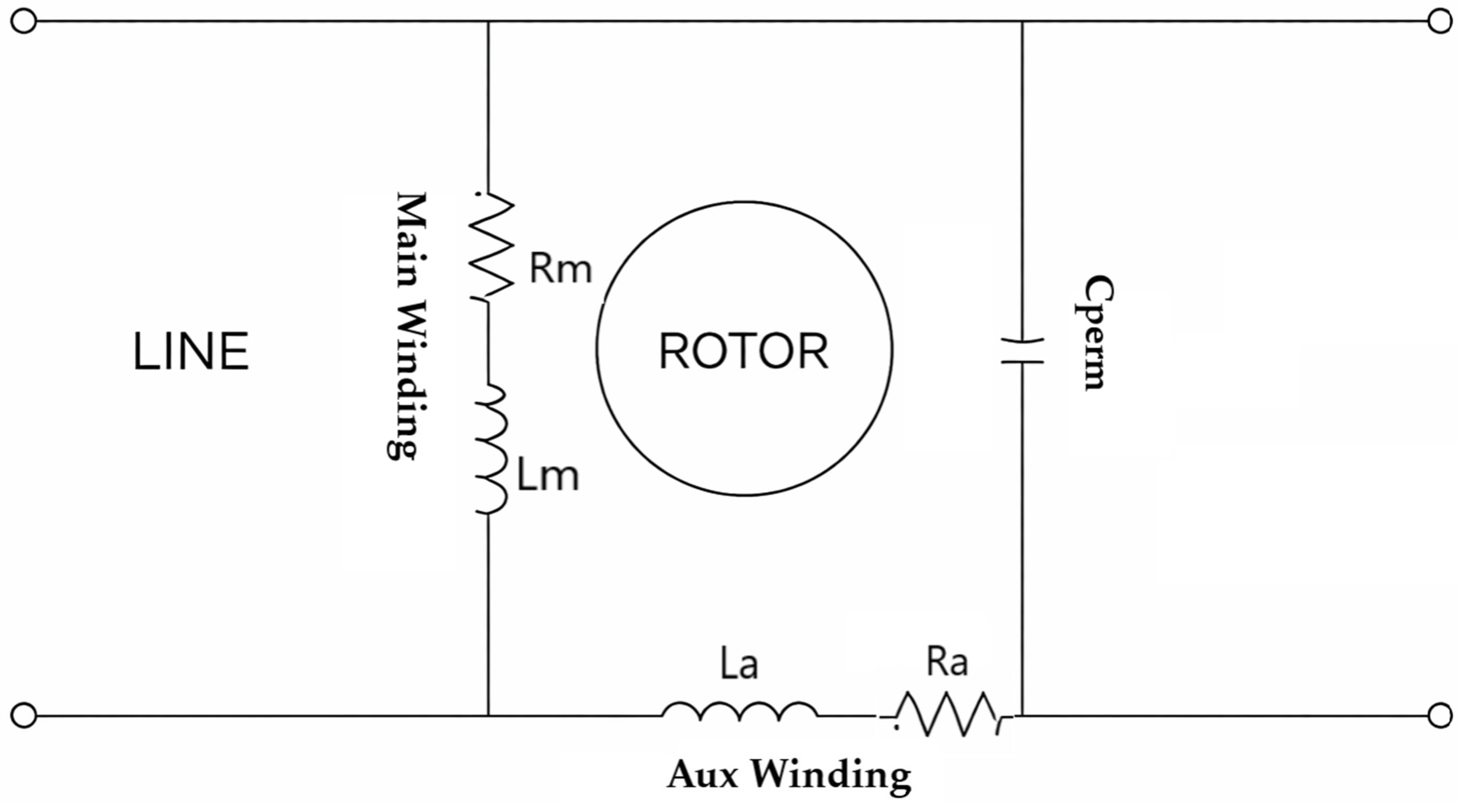
11]. To create the required phase shift in the auxiliary winding current, a phase-shifting capacitor is connected in series with the auxiliary winding. The auxiliary winding–capacitor combination is then connected in parallel with the main winding, which is directly supplied from the motor terminals [
12].
Nowadays, single-phase induction motors, which are widely used in industry, can be classified according to the type of capacitor employed. The first type is the permanent capacitor motor, used in applications where low starting torque is sufficient, such as impeller fans. The second type is the start-permanent capacitor motor, employed in applications requiring high starting torque, such as cranes, mixing machines, and compressors. In permanent capacitor motors, the capacitor is connected in series with the auxiliary winding and, consequently, in parallel with the main winding, remaining in the circuit during continuous operation.
In start-permanent capacitor motors, a high-capacitance starting capacitor is connected in parallel with the permanent capacitor and is disconnected when the motor reaches approximately 75% of its rated speed. The disconnection of this capacitor is typically achieved using a centrifugal switch or an electronic relay [
13]. The schematic diagram of the permanent capacitor motor is shown in
Figure 1.
Consequently, torque pulsations occur at twice the stator frequency [
14]. The pulsating torque arises from the interaction of the forward and backward rotating magnetic fields, which causes the instantaneous power and electromagnetic torque drawn from the supply to vary with time [
15]. The pulsating torque produces a humming effect, which causes single-phase motors to operate with higher noise levels compared to polyphase motors [
14].
3. Impact of Design Parameters on Acoustic Noise in Single-Phase Induction Motors
In three-phase induction motors, the air-gap flux distribution is nearly circular due to the symmetrical winding structure. However, in single-phase induction motors, it should be noted that the phase displacement between the main and auxiliary winding currents is not exactly 90° under most operating conditions. Therefore, a perfectly circular electromagnetic flux trajectory cannot be expected [
16].
This asymmetric flux distribution in the air gap may lead to the generation of magnetic field harmonics and localized magnetic saturation. Furthermore, in order to establish a phase difference between the main and auxiliary windings, the number of turns is intentionally designed to be different, and the conductor diameters are selected accordingly. As a result, the currents drawn by the two windings ( and ) are not identical. Whether the magnetic core reaches saturation and the magnitude of torque ripple are directly related to these winding parameters.
In addition to design optimization, certain manufacturing-related factors also directly influence motor performance. One of the most critical factors is stator–rotor eccentricity. Parameters such as efficiency, starting performance, thermal behavior, noise, and vibration levels are significantly affected by these factors. In this study, these performance parameters are examined particularly in terms of their contribution to noise and vibration characteristics.
3.1. Effect of Capacitor Selection
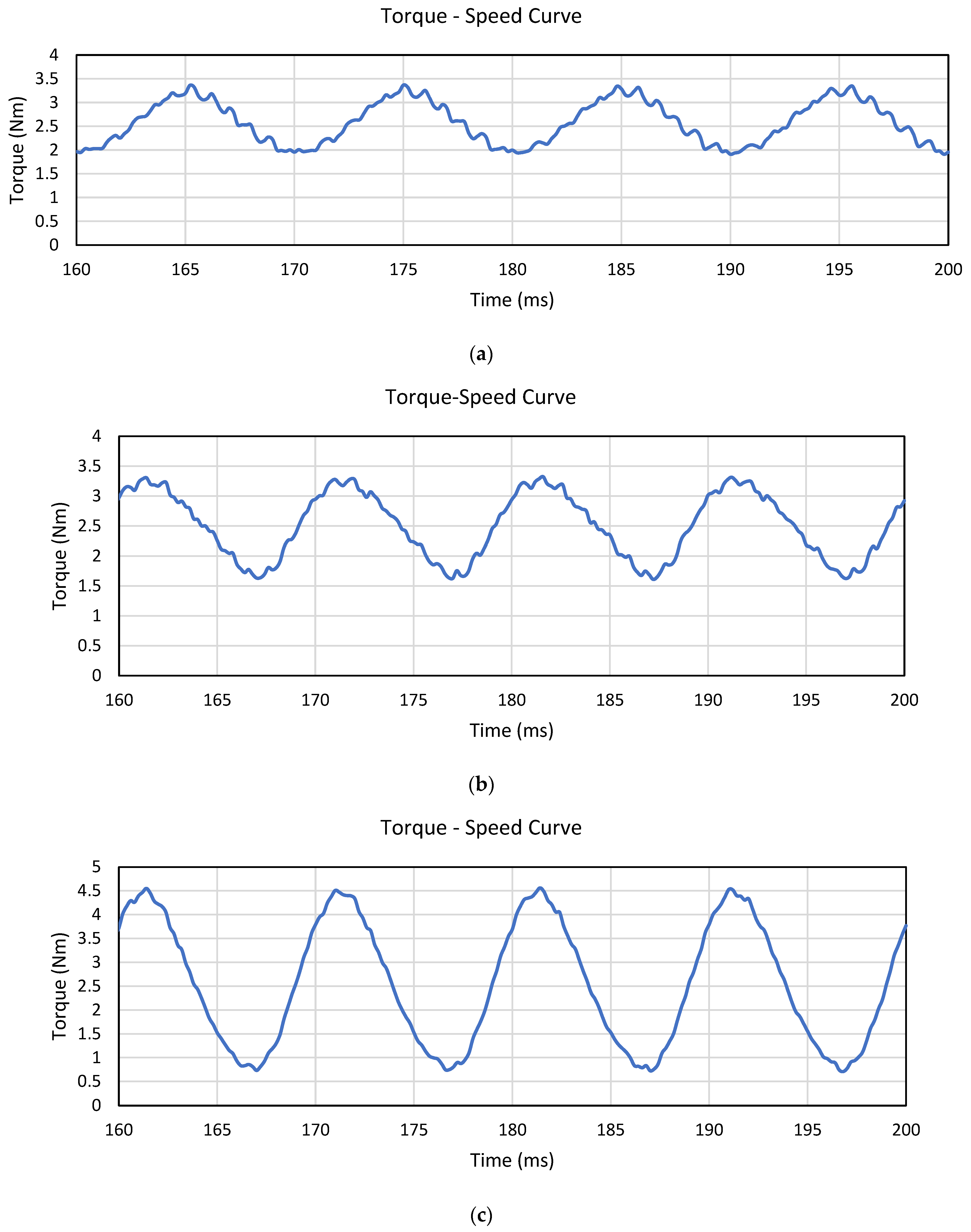
In order to evaluate the effect of capacitor selection on motor performance, all motor parameters were kept constant and FEM analyses were conducted using 15 µF, 20 µF, and 25 µF capacitors. Based on these analyses, the winding inductances and the torque–speed characteristics under nominal operating conditions were examined and interpreted.
Table 1 presents the influence of capacitor variation on selected motor parameters. Here,
,
,
, and
α represent the main winding current, auxiliary winding current, capacitor voltage, and transformation ratio, respectively. The transformation ratio is defined as given in Equation (1):
In this context,
, and
represent the number of turns of the auxiliary winding, and the number of turns of the main winding, respectively.
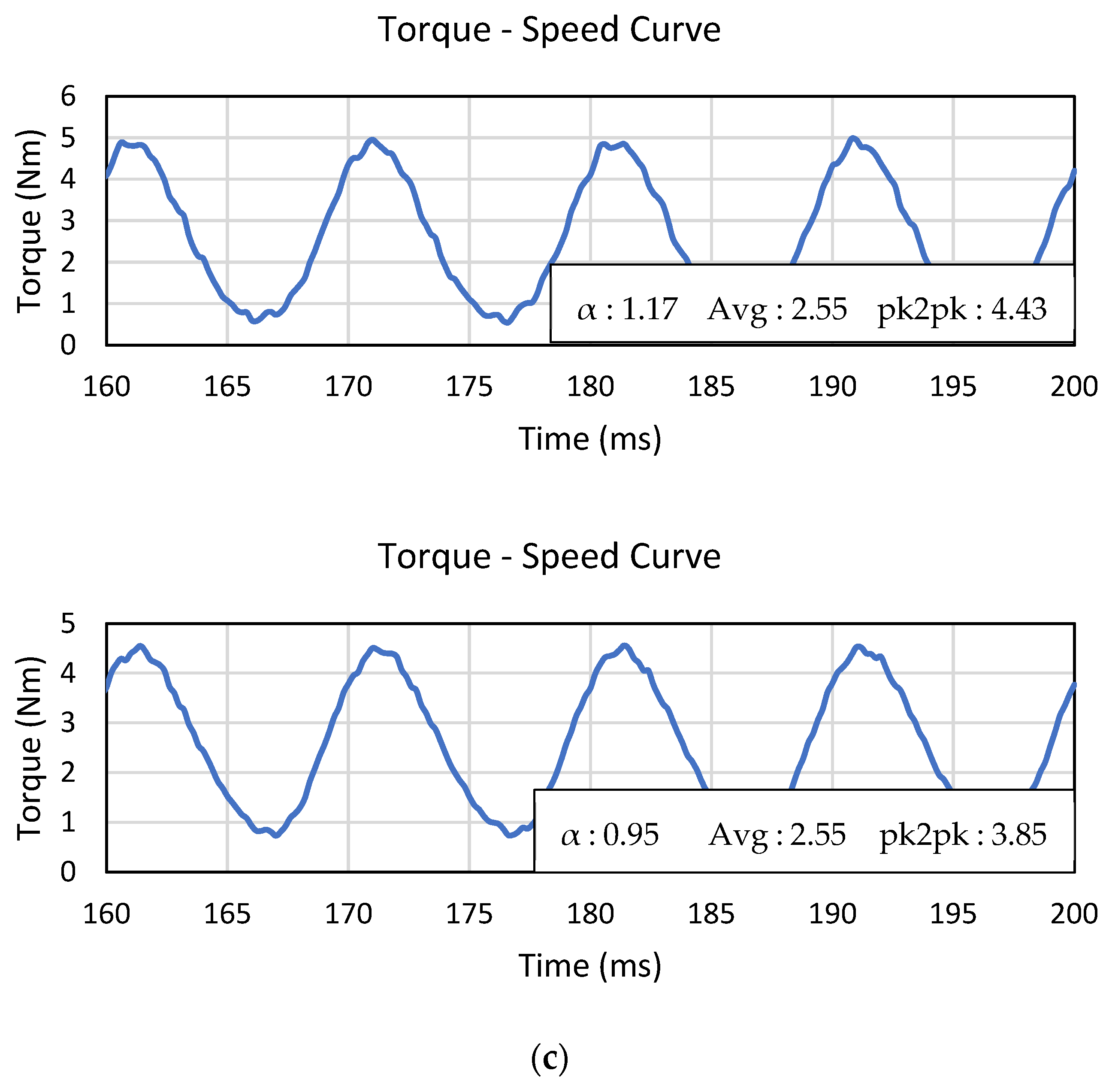
Figure 2 illustrates the variation in the torque–speed curves under nominal operating conditions as a result of capacitor changes in the motor with a transformation ratio of 0.95. The phase differences between the main and auxiliary winding currents are presented in
Table 1.
One of the principal reasons why the phase displacement deviates from 90 degrees is that a single-phase supply produces two magnetic field components in the stator, namely forward and backward rotating fields. Each of these oppositely rotating fields induces torques in opposite directions on the rotor conductors [
13]. Consequently, the magnetic flux distribution in the air gap is not symmetrical as in a three-phase motor, but rather exhibits an elliptical pattern. This asymmetry leads to torque pulsations even under nominal operating conditions. The asymmetric flux density in the air gap, which is converted into electromagnetic force, generates non-uniform radial forces on the stator teeth. These forces, together with torque ripple, constitute a significant source of increased noise and vibration [
17]. The selection of the capacitor directly affects the phase difference between the two windings and, consequently, the flux distribution. Therefore, among three motors with identical windings, the motor equipped with a 15 μF capacitor is expected to exhibit a lower noise level. The disadvantage of using a 15 μF capacitor is the reduced starting torque; however, since a start-and-run capacitor motor configuration is employed, the reduction in starting torque has been disregarded in this study.
3.2. Impact of Main–Auxiliary Winding Configuration on Motor Performance
As previously stated, the magnetic field and winding structure of a single-phase induction motor are inherently asymmetric. Therefore, the selection of the number of turns in the main and auxiliary windings, as well as the transformation ratio (α) representing the relationship between them, has a significant influence on the motor characteristics. Understanding these effects facilitates approaching an optimal motor design during the design stage.
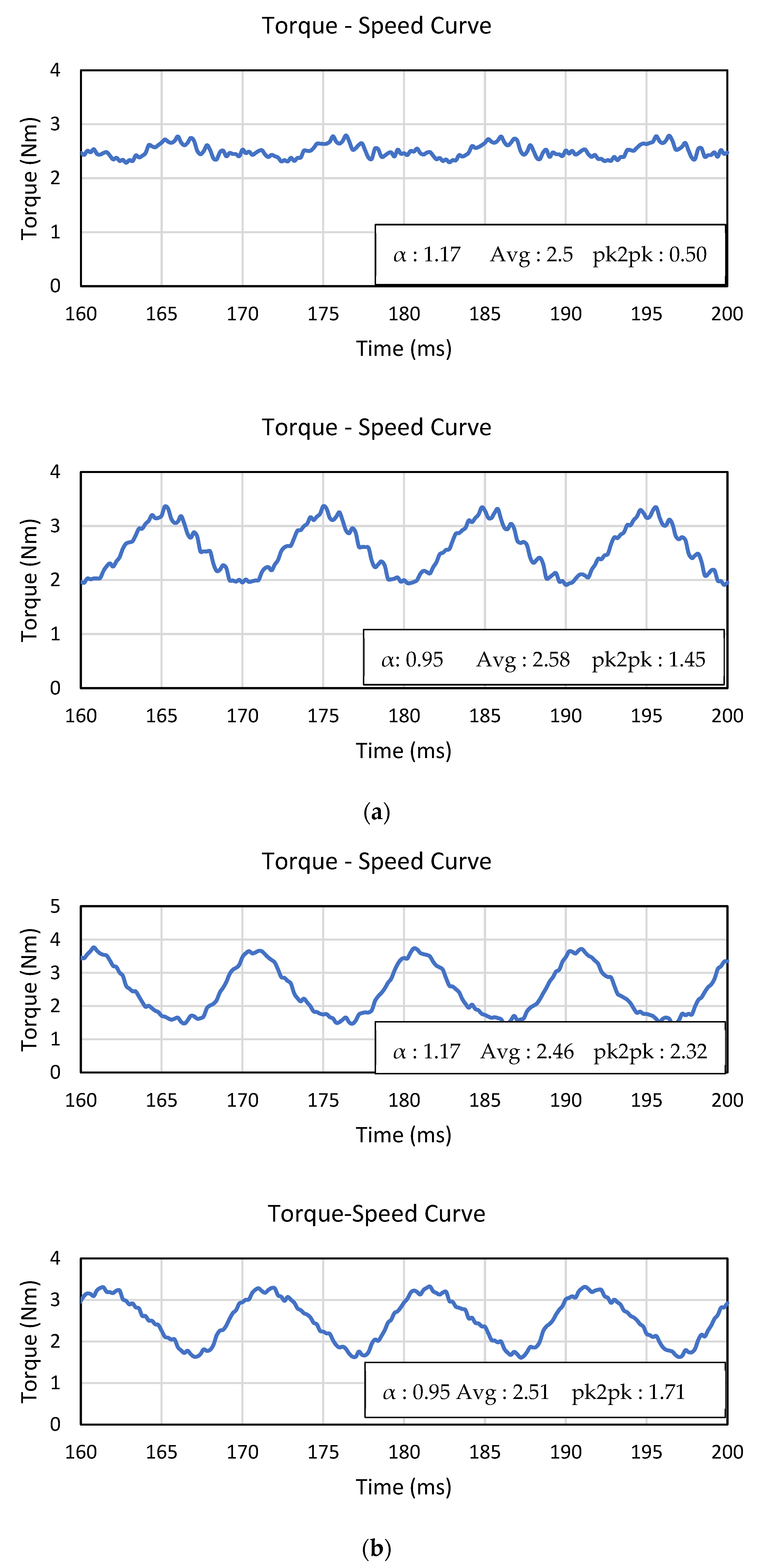
In this study, in order to examine the influence of the number of turns, the torque–speed and winding inductance characteristics of two different motors with transformation ratios of 0.95 and 1.17 were compared.
Table 2 presents several characteristic parameters of the motor for two different winding configurations and various capacitor selections. The corresponding characteristic curves are illustrated in
Figure 3.
An examination of
Table 2 indicates that, for constant winding turns, increasing the capacitance of the run capacitor leads to an increase in the auxiliary winding current, while the main winding current decreases. This directly results in an increase in the starting torque of the motor. However, it also causes an increase in the magnetic flux densities in both the stator and rotor teeth. The increased flux density, particularly evident in the rotor teeth, initiates local saturation in the narrow tooth-tip regions. These local saturations reduce the magnetic permeability and consequently lead to a relative distortion of the air-gap flux distribution compared to the low-flux-density condition. As the flux densities at the stator and rotor tooth roots continue to increase, the magnetic reluctance becomes dependent on the rotor position. As a result, the variation in reluctance gives rise to increased ripples in the inductance characteristics. This behavior is numerically demonstrated in
Table 2. Such ripples in the inductance and torque characteristics generate radial electromagnetic forces and, consequently, acoustic noise. As the relative torque and inductance increase, a corresponding increase in noise levels becomes inevitable.
On the other hand, when the transformation ratio is increased at the same capacitance value—meaning that the number of turns in the auxiliary winding exceeds that of the main winding—the phase difference between the two winding currents exceeds 90°. For instance, when two different motors equipped with a 20 μF capacitor are examined, it can be observed that the inductance ripple increases by approximately three to four times, while the torque ripple increases by nearly 40%. Under these conditions, an increase in electromagnetic vibrations is expected, which in turn physically manifests as increased acoustic noise. Similar increases in inductance ripple are also observed for the motor equipped with a 25 μF capacitor. In the previous section, the importance of the correlation between the main winding, auxiliary winding, and capacitor was emphasized. When two motors with different winding configurations but both employing a 15 μF capacitor are analyzed, an increase in inductance ripple is again observed. However, unlike the other cases, a reduction in torque ripple is obtained. In this study, the electromagnetic torque is expressed using a conventional formulation based on inductance variation with respect to rotor position, as given in Equation (2).
In this context,
,
,
,
,
,
and
represent torque, main winding current, auxiliary winding current, main winding self-inductance, auxiliary winding self-inductance, mutual inductance between the main and auxiliary windings and rotor position, respectively. As indicated by this relationship, the torque is influenced not only by the position-dependent variation of inductance but also by the square of the current. Since the current levels are relatively lower in this case, the torque characteristic becomes smoother. From this perspective, ensuring the proper correlation between the windings and the capacitor is beneficial for suppressing the harmonic components of torque. Even if the inductance ripple increases, acoustic noise is physically more sensitive to torque ripple than to inductance variations alone. In addition to this qualitative interpretation, the relationship between inductance variation, torque ripple, and acoustic noise can be described through a simplified coupling mechanism. As indicated by Equation (2), the electromagnetic torque is directly influenced by the rotor-position-dependent derivative of inductance, showing that torque ripple is governed by the angular variation of inductive coupling. The resulting air-gap flux-density harmonics generate radial electromagnetic pressure acting on the stator surface, which can be expressed as
where
is the radial electromagnetic pressure, B is the air-gap flux density, and
is the permeability of free space. Since the air-gap region has permeability close to free space, this formulation provides a valid approximation. These force components excite the structural vibration modes of the stator, and the resulting vibration manifests as acoustic noise. This provides a semi-quantitative framework linking electromagnetic design parameters to noise generation.
3.3. Effect of Stator–Rotor Eccentricity
As discussed in the previous sections, in addition to electromagnetic noise originating from the magnetic field in the air gap, acoustic noise also includes mechanical noise generated by bearings, stator–rotor eccentricity, and mechanical imbalances [
3]. Andrei Negoita et al. [
18] conducted a detailed study investigating the effect of stator–rotor eccentricity on the sound level of a single-phase induction motor. Their results demonstrated that, in a motor with static eccentricity, the radial force (expressed in Newtons) increases, leading to a corresponding rise in noise level. The variation of inductance in the air gap depends on the magnetic permeability of the air-gap region, which in turn is directly related to changes in the air-gap length. For this reason, eccentricity must be taken into consideration [
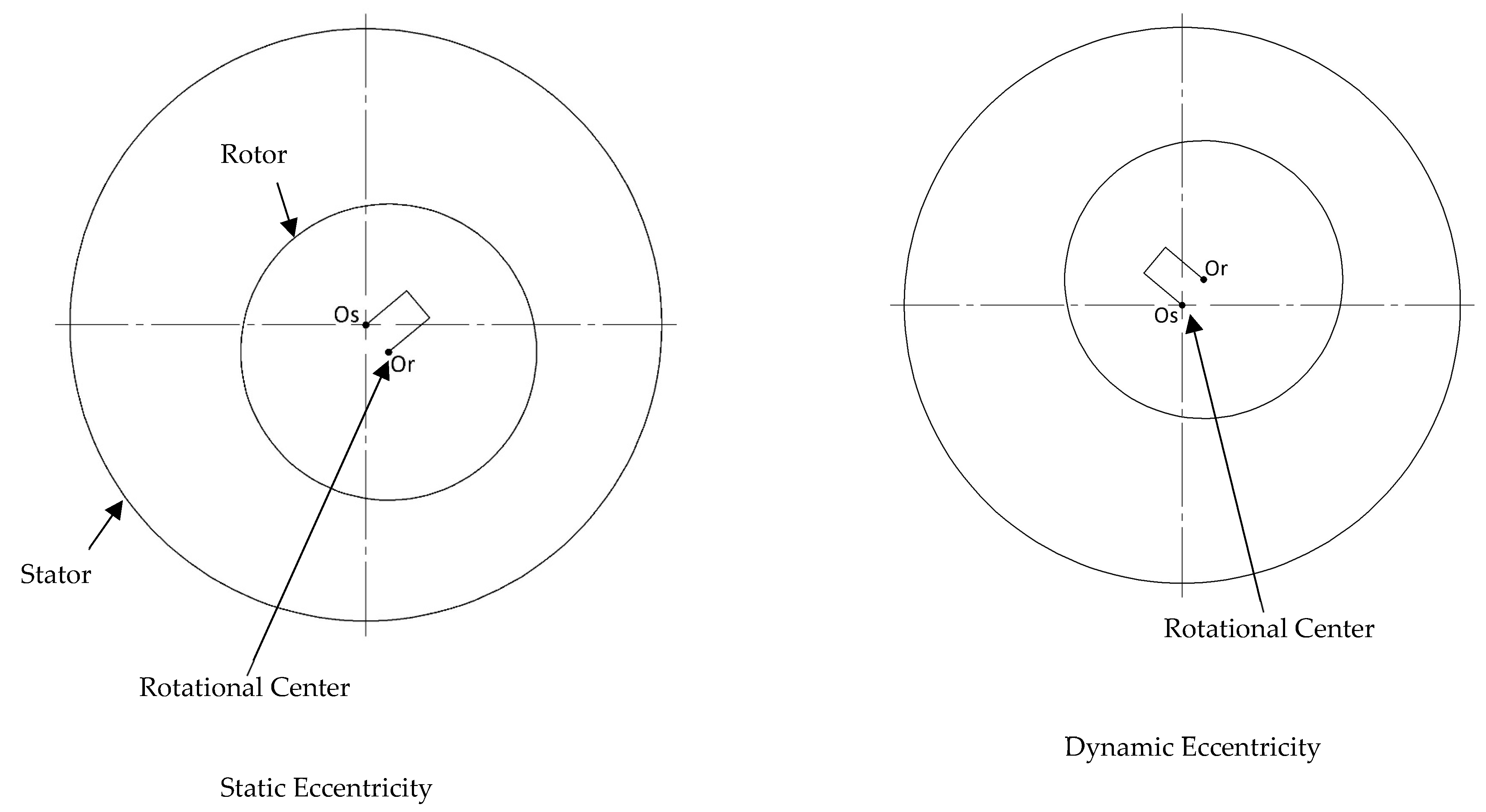
13]. In other words, stator–rotor eccentricity resulting from manufacturing tolerances or faults leads not only to magnetic noise due to air-gap distortion but also to mechanical noise caused by unbalanced forces acting on the bearing assemblies. In order to observe this effect, the designed motors were manufactured under two different conditions: with minimum eccentricity and with intentionally introduced eccentricity of approximately 30%. The experimental results obtained from these two cases were then comparatively evaluated.
Figure 4 illustrates representative stator–rotor relative positions under static and dynamic eccentricity conditions.
4. Experimental Validation of Prototype Motors via Acoustic Noise Measurements
In the previous sections, factors affecting the noise level of single-phase induction motors were analyzed from both electromagnetic and mechanical perspectives. The influence of magnetic flux distributions in the air gap on the main and auxiliary winding self-inductances and on the electromagnetic torque was examined. Additionally, the effects of capacitor and winding variations on the winding currents, magnetic saturation in the stator and rotor, and the phase difference between the windings were evaluated based on the analysis results. In this section, the acoustic noise levels of the manufactured prototype motors were measured under no-load conditions according to the procedure specified in IEC 60034-9 [
19]. Acoustic noise measurements were performed in a semi-anechoic laboratory environment using a calibrated Class2 sound level meter (MRC, SL-4035SD) positioned at a distance of 1 m from the motor surface. Each measurement was repeated three times and the average value was recorded in order to minimize experimental uncertainty. The measured noise levels are presented comparatively in
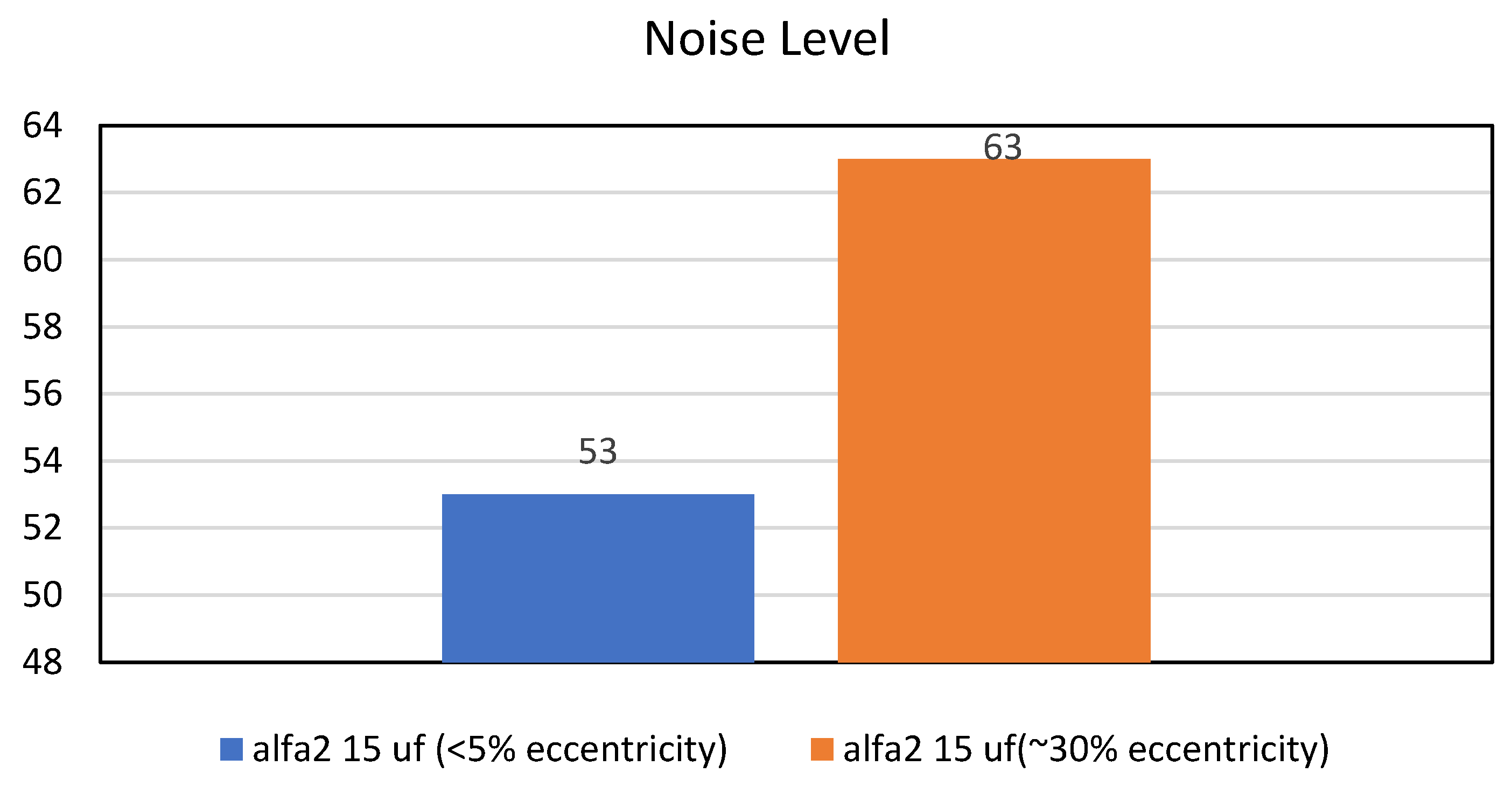
Table 3, expressed in decibels (dB). Two prototypes of the motor equipped with a 15 μF run capacitor were produced: one with minimal eccentricity (<5%) and the other with approximately 30% eccentricity. The corresponding noise levels of these two motors are compared in
Figure 5, highlighting the effect of rotor–stator eccentricity on acoustic performance.
The standard deviation of repeated measurements was found to be within 0.4–0.5 dB, indicating good repeatability of the experimental setup. The overall measurement uncertainty is estimated to be within ±0.8 dB. The variation between repeated measurements remains significantly lower than the differences observed between test cases. When
Table 2 and
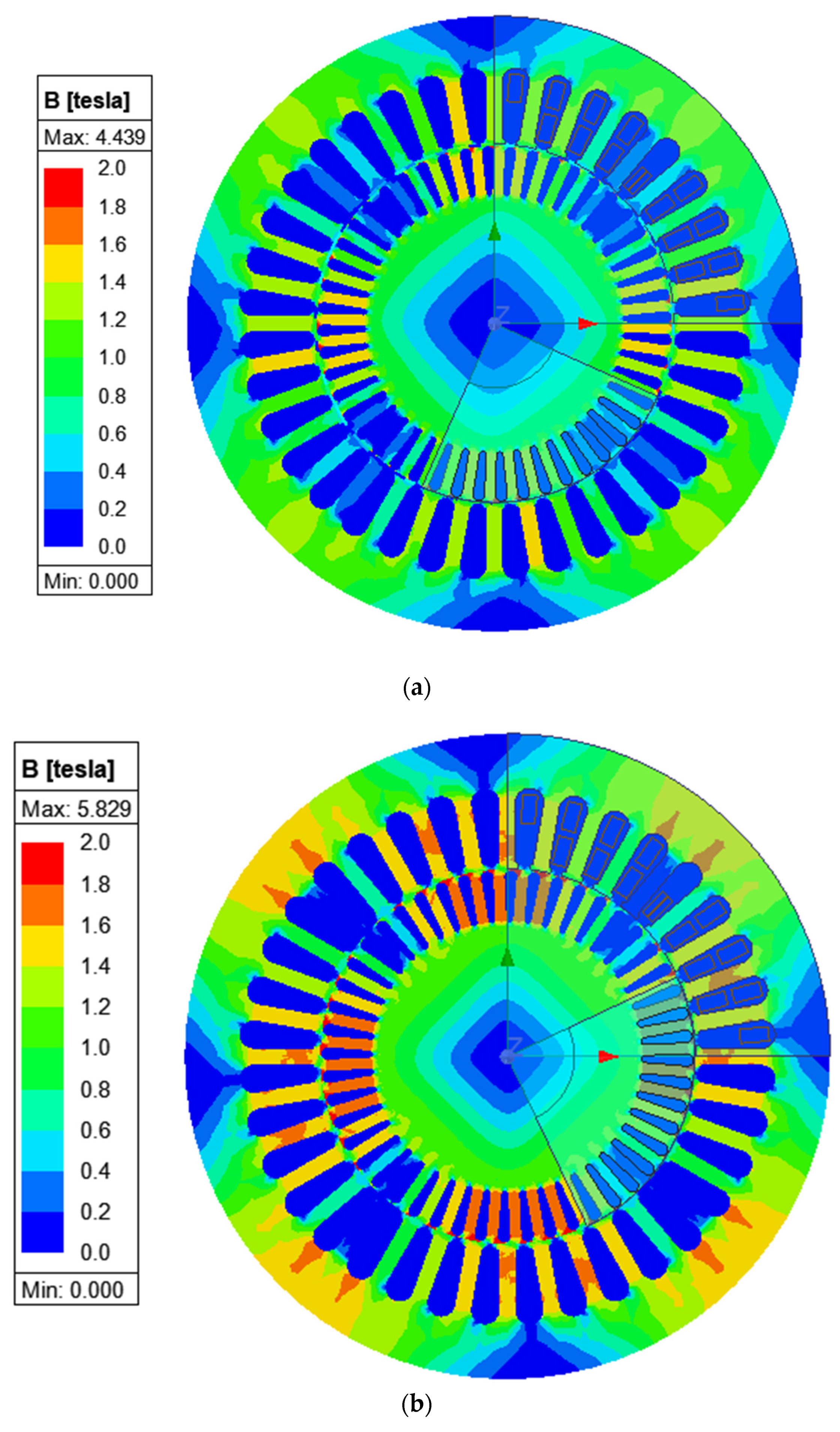
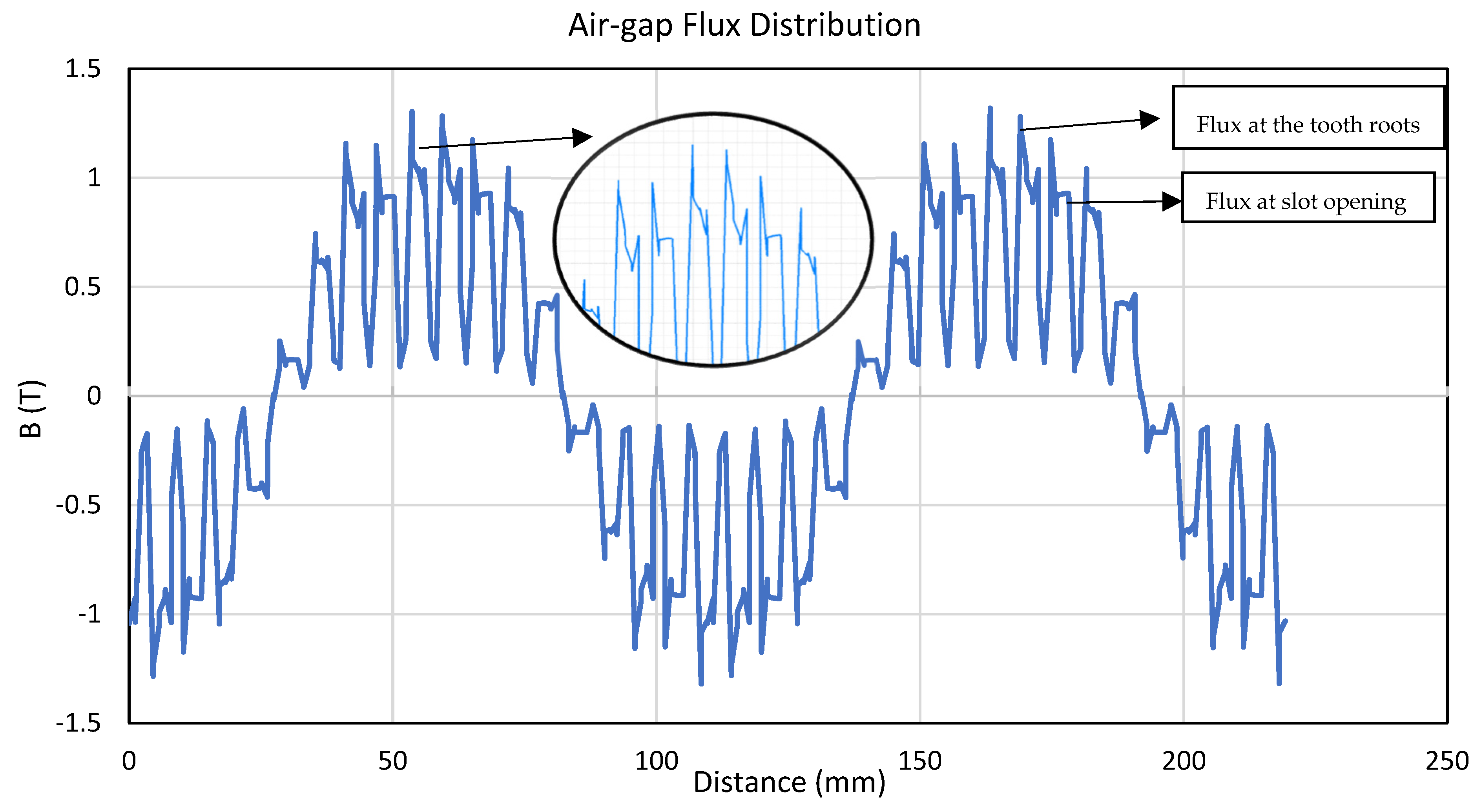
Table 3 are evaluated together, they clearly demonstrate the coupled influence of capacitor selection, winding configuration, and rotor eccentricity on torque ripple and acoustic noise levels. The results show that variations in these parameters simultaneously affect electromagnetic behavior and noise generation, indicating a consistent and monotonic relationship. An increase in torque ripple is consistently associated with an increase in the measured noise level, as it reflects the underlying electromagnetic force harmonics acting on the stator structure. Although the correlation is not strictly linear due to the influence of structural and mechanical factors, the observed trend provides quantitative support for the proposed coupling between electromagnetic excitation and acoustic noise. The primary cause of the observed increase in acoustic noise levels is the distortion of the air-gap magnetic flux distribution, which leads to torque ripple, combined with the increased bearing loads resulting from eccentricity. The air-gap flux distribution is illustrated in
Figure 6. The differences between the flux densities at the stator and rotor tooth roots and those at the regions corresponding to the stator slot openings result in position-dependent variations in inductance and, consequently, in torque ripple. These instantaneous variations contribute directly to the increase in noise levels. Furthermore, as expressed in Equation (2), the torque depends not only on the inductance but also on the current magnitude. Therefore, by selecting an appropriate combination of winding configuration and run capacitor, the impact of inductance variations on torque fluctuations can be minimized, thereby reducing the resulting acoustic noise.
In
Figure 7, the differences in magnetic flux densities between motors with two different winding and capacitor configurations are clearly illustrated. The simulations were performed using Ansys Maxwell (Ansys Inc., Canonsburg, PA, USA), version 2022 R2. The implications of these differences on motor performance have been discussed throughout this manuscript, particularly in the Discussion section.
5. Discussion
The application scope of electric motors continues to expand, making low noise a critical design requirement. Unlike three-phase machines, single-phase induction motors are typically supplied directly from the mains, limiting control-based noise reduction methods. Therefore, acoustic performance in these machines primarily depends on electromagnetic design and manufacturing quality.
The results show that magnetic saturation leads to asymmetric flux distribution in the air gap, increasing harmonic content. These harmonics generate radial electromagnetic force components that excite structural vibration modes, resulting in acoustic noise. Torque ripple reflects this behavior as a consequence of time-varying electromagnetic forces.
Noise generation is strongly influenced by the interaction between capacitor selection and winding configuration. Improper phase shift increases field asymmetry, harmonic content, and force amplitudes. In addition, rotor eccentricity introduces air-gap variations that further enhance harmonic excitation and mechanical loading.
These findings indicate that acoustic noise cannot be attributed to a single parameter but arises from the coupled interaction between electromagnetic field distortion, force harmonics, and structural response.
It should be noted that the peak-to-peak torque ripple values obtained from FEM are influenced by modeling assumptions and numerical sensitivity. However, the simulations reliably capture the relative trends between different design configurations, and torque ripple is therefore used as a comparative indicator rather than an absolute measure.
From a design perspective, low-noise operation requires a holistic approach in which capacitor selection, winding configuration, and geometric tolerances are jointly optimized. Similar observations regarding electromagnetic noise sources, eccentricity effects, and mitigation approaches have been reported in previous studies [
20,
21,
22].