Article

Dry and Wet Modal Comparison of an Electro-Hydraulic Pump and Its Electromagnetic Vibration Analysis

1
Naval University of Engineering, Wuhan 430033, China
2
National Key Laboratory on Ship Vibration and Noise, Wuhan 430033, China
*
Author to whom correspondence should be addressed.
Appl. Sci. 2026, 16(8), 3626; https://doi.org/10.3390/app16083626
Submission received: 15 March 2026 / Revised: 4 April 2026 / Accepted: 7 April 2026 / Published: 8 April 2026
(This article belongs to the Section Mechanical Engineering)

Abstract

The electro-hydraulic pump (EHP), as the primary power component of the electro-hydrostatic actuator, typically operates in a wet environment filled with hydraulic oil, thereby experiencing vibration response alterations due to the added mass of the fluid. Accurate identification of the wet modal characteristics is essential for improving the fidelity of electromagnetic vibration prediction in EHPs. In this work, an integrated EHP is investigated. A finite-element model is established to perform dry and wet modal analyses, from which the first nine natural frequencies and associated mode shapes are extracted. Dry and wet experimental modal tests are then conducted using an impact-hammer setup to validate the numerical model. The results indicate a systematic reduction in natural frequencies under oil-filled conditions, with more pronounced shifts in the lower-order modes; a maximum decrease of 10.92% is observed. On this basis, the stator tooth electromagnetic forces are obtained from two-dimensional electromagnetic finite-element simulations, and vibration responses are predicted via modal superposition using either dry or wet modal parameters. Finally, vibration measurements are performed under oil-filled operating conditions. The measured spectra exhibit pronounced tonal components at the electrical fundamental frequency and its even harmonics, and wet modal-based electromagnetic vibration prediction improves the accuracy by 78.90% relative to the dry modal-based prediction. These findings provide both theoretical support and practical guidance for low-vibration and low-noise design of EHPs.

1. Introduction

As the primary power unit of electro-hydrostatic actuators, EHPs have been widely adopted in aerospace, industrial automation, and construction machinery due to their high power density, fast dynamic response, and compact architecture [1,2,3]. Unlike conventional hydraulic pumps, an EHP typically features a highly integrated motor–pump configuration, where the electric motor often operates in a “wet” condition, i.e., fully immersed in hydraulic oil. Although this immersed design effectively addresses thermal management and lubrication requirements [4], it also means that the pump housing and rotating components are continuously subjected to complex oil-filled operating conditions [5]. In such an oil environment, rotor–oil interactions can induce hydrodynamic noise [6]; meanwhile, when the structure vibrates in a fluid medium, the surrounding fluid introduces added mass and added damping, thereby altering the system’s dynamic characteristics [7]. Therefore, conducting wet modal analysis of EHPs to accurately identify their dynamic properties under realistic operating conditions is a prerequisite for reliable vibration prediction and subsequent structural optimization.
Within the broader framework of fluid-loaded structural dynamics, wet modal analysis has been extensively developed for liquid-filled vessels, hydraulic pipelines, and fluid-conveying systems [8,9,10]. Through modal testing [11], coupled solid–acoustic modeling [12,13], and analyses of added mass and added damping [14], previous studies have clarified the systematic effects of fluid media on natural frequencies, damping, and modal distributions. These advances have further been used to interpret the generation mechanisms of vibration and noise in fluid-power units [15]. On this basis, similar approaches have been extended to electrical submersible pumps [16], submerged pump rotors [17], submerged motor stators [18], and highly integrated magnetic-levitation pump rotors [7], demonstrating that fluid-added effects can substantially modify the modal properties of rotating machinery. However, most existing studies focus on rotors, impellers, or standalone stators in water media, whereas the modal evolution of integrated oil-filled EHPs at the system level, and its implications for subsequent response prediction.
In parallel, electromagnetic vibration in electric machines has developed into another relatively independent line of research. Previous studies have systematically analyzed the relationships among electromagnetic force waves, structural modes, and sound radiation, and have applied such approaches to pump motors [19], submerged tubular linear motors [20], cylindrical shell representations of motor housings [21], and in-wheel motors [22]. Nevertheless, the structural dynamic basis adopted in these studies is commonly derived from dry-state models or idealized shell structures, and the modal reconfiguration induced by the internal fluid medium has rarely been considered explicitly. By contrast, vibration studies on pumps and EHA/EHP-related equipment have mainly focused on pressure pulsation, flow-induced vibration, mechanical excitation, and noise-source identification, such as the dynamic response of axial piston pumps [23], source identification in EHA internal gear pumps [24], flow-induced vibration of centrifugal pumps [25], the influence of working media on hydraulic pump vibration and noise [26], and the structural deformation of the pump body under fluid pressure [27]. Taken together, the literature has largely addressed the influence of fluid loading on modal characteristics and the role of electromagnetic excitation in vibration response as two separate issues. Yet these two lines of research have not been effectively integrated at the level of oil-filled wet modes and electromagnetic vibration prediction. This gives rise to an unresolved scientific question: for highly integrated oil-filled EHPs, do fluid-induced wet modal changes alter the coupling basis between electromagnetic forces and structural modes, and thereby affect the accuracy of electromagnetic vibration response prediction? Direct quantitative evidence and experimental validation remain scarce.
To address this issue, the present study investigates the modal differences between the dry and fully oil-filled states of an EHP and their influence on the accuracy of electromagnetic vibration prediction. First, dry-state and wet-state finite-element models are established, and their accuracy is validated against modal parameters obtained from impact-hammer tests. Second, the electromagnetic forces on the stator tooth surfaces are extracted by two-dimensional electromagnetic finite-element analysis, and the vibration responses are predicted within a unified framework using dry and wet modal parameters, respectively. Finally, the predicted results are assessed against whole-pump vibration measurements under oil-filled operating conditions.
The main contributions of this study are as follows:
(1)
It reveals the modal migration characteristics of EHPs from dry to oil-filled wet conditions and identifies the key vibration-sensitive regions, thereby clarifying how the internal oil medium modifies the structural dynamics.
(2)
It establishes a quantitative relationship between wet modal variation and prediction errors in electromagnetic vibration analysis, highlighting the critical role of modal basis selection in electromagnetic–structural coupled response prediction.
(3)
Through cross-validation between simulations and experiments, it provides new empirical evidence for the coupling mechanism between fluid loading and electromagnetic excitation in immersed electromechanical systems.

2. Theoretical Analysis

The theoretical analysis in this section is established for the load-bearing structure of the EHP under non-rotating and static oil-filled conditions and is based on the following assumptions: the structure is treated as a small-deformation, linear–elastic system; the wet condition corresponds to a fully oil-filled cavity without free surface motion and without mean flow and only small perturbations are considered; the hydraulic oil is idealized as a homogeneous medium with constant properties. Under the acoustic approximation, only the fluid density and compressibility are retained in the dynamic model, whereas viscous shear effects, thermal dissipation, and cavitation are neglected. In addition, since both the modal tests and the simulations are performed for a non-rotating configuration focusing on the housing-type load-bearing structure, rotor eccentricity, oil-film dynamics, gyroscopic effects, and the associated stiffness and damping variations are not included.

2.1. Dry Modal Theory

Under dry conditions, the structural dynamics of an EHP can be described by Equation (1) [28]:
[ M s ] { u ¨ } + [ C s ] { u ˙ } + [ K s ] { u } = { F ( t ) }
where [ M s ] , [ C s ] and [ K s ] are the mass, damping, and stiffness matrices, respectively; F ( t ) is the external load vector; and { u ¨ } , { u ˙ } and { u } denote the acceleration, velocity, and displacement vectors.
For free vibration, neglecting external loads and adopting the undamped approximation yields the dry modal eigenvalue problem in Equation (2):
[ K s ] ω d 2 [ M s ] ϕ d = { 0 }
where ω d is the dry natural circular frequency, f d = ω d / ( 2 π ) is the corresponding dry natural frequency, and ϕ d is the associated mode shape. This formulation follows the classical framework of linear structural modal analysis.
After the hydraulic oil is introduced, the dynamic characteristics deviate from those of the dry structure. For the static oil-filled modal problem considered in this study, this deviation can be interpreted primarily in terms of fluid-induced added inertia and acoustic–structure coupling effects.

2.2. Added Mass

When the motor interior is filled with oil, vibration of the structural boundary accelerates the adjacent fluid, generating an acceleration field that in turn exerts an inertial reaction force on the structure. For small-amplitude linear responses, and with viscous shear and higher-order flow effects neglected, this fluid inertial reaction can be represented by an added-mass matrix [ M a ] , such that the mass term in the dry structural dynamic equation is systematically modified as [29,30]
( [ M s ] + [ M a ] ) { u ¨ } + [ C s ] { u ˙ } + [ K s ] { u } = { F ( t ) }
The added mass [ M a ] is closely related to the oil density, the geometry of the fluid domain, and the distribution of the normal velocity associated with the structural mode shapes. For lower-order modes, a larger portion of the structural surface participates in the motion and the normal velocity component is generally more pronounced; consequently, the added-mass effect is typically more significant. Under the undamped approximation, the wet modal eigenvalue problem can be written as
[ K s ] ω w 2 ( [ M s ] + [ M a ] ) ϕ w = { 0 }
where ω w and ϕ w denote the wet natural circular frequency and the corresponding mode shape, respectively. This equation indicates that compared with the dry case introducing added mass results in an overall reduction in natural frequencies. For a given mode, let m s denote the dry generalized mass and m a the fluid-induced added generalized mass. If the fluid loading primarily modifies the modal mass while causing only limited perturbation to the mode shape, the wet natural frequency can be approximately expressed as
f w f d m s m s + m a
Equation (5) is an explanatory relation based on a generalized-mass approximation, introduced to illustrate the dominant mechanism of wet natural frequency reduction, rather than an exact analytical solution of the fully coupled system. The actual finite-element simulations in this work are performed using the acoustic–structure coupling formulation presented in Section 2.3.

2.3. Governing Equations of Acoustic–Structure Coupling

In finite-element simulations, an oil-filled cavity is often idealized as a homogeneous, linear, inviscid, and slightly compressible fluid medium, and an acoustic fluid–structure coupling formulation is adopted under the assumptions of a quiescent fluid, no mean flow, and small perturbations [31,32]. The corresponding wave equation is given by
2 p 1 c 2 2 p t 2 = 0
where p is the acoustic pressure in the fluid and c is the speed of sound.
Within this linear acoustic approximation, the fluid–structure interface satisfies the continuity of normal motion and equilibrium of normal traction, while tangential viscous shear effects are neglected. Applying the Galerkin method to discretize Equation (6) and introducing the acoustic finite-element formulation yields the discretized governing equation for the fluid domain:
[ M f ] { p ¨ } + [ C f ] { p ˙ } + [ K f ] { p } = ρ [ R ] { u ¨ }
where [ M f ] , [ C f ] and [ K f ] are the fluid mass, damping, and stiffness matrices, respectively; { p } is the nodal pressure vector; ρ is the fluid density; and [ R ] is the fluid–structure interaction matrix. For the ideal closed-cavity wet modal analysis considered in this work, intrinsic fluid dissipation is generally neglected; therefore, [ C f ] is retained only in the general form, and [ C f ] = 0 when no additional damping or absorbing boundary is prescribed. Let Γ f s denote the fluid–structure interface and n the outward unit normal vector on the interface; then [ R ] is defined as
[ R ] = Γ f s [ N f ] T n T [ N s ] d Γ
where [ N f ] and [ N s ] are the shape-function matrices of the acoustic elements and the structural elements, respectively.
Combining Equations (1) and (7) leads to the coupled acoustic–structure governing equations:
[ M s ] 0 ρ [ R ] [ M f ] { u ¨ } { p ¨ } + [ C s ] 0 0 [ C f ] { u ˙ } { p ˙ } + [ K s ] [ R ] T 0 [ K f ] { u } { p } = { F ( t ) } 0

3. Dry and Wet Modal Comparison

3.1. Dry and Wet Modal Simulations

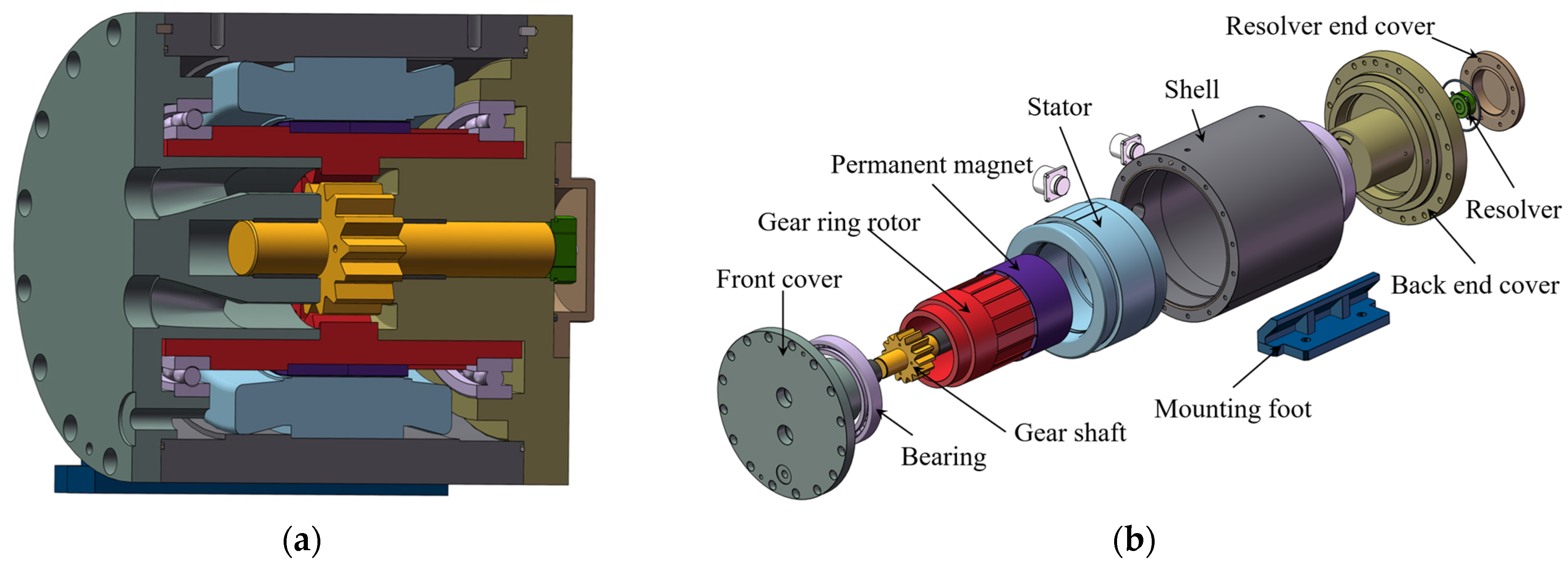
The EHP investigated in this work is shown in Figure 1. It mainly consists of a stator, a ring-gear rotor, a gear shaft, and front and rear end covers. Specifically, Figure 1a presents a three-dimensional structural view for showing the internal features of the pump, while Figure 1b provides an exploded assembly view to clarify the constituent components and their assembly relationships. The main dimensions and performance parameters are listed in Table 1. To meet the compactness and high-integration requirements of the EHP, the motor rotor is designed as a hollow structure, and the external ring gear of the internal gear pump is directly integrated into the inner wall of the rotor. Specifically, the outer surface of the ring gear functions as the motor rotor for electromagnetic energy conversion, whereas the inner surface serves as the driving ring gear of the hydraulic pump and meshes with the internal gear. When driven by the motor, the ring-gear rotor rotates and actuates the internal gear, thereby accomplishing the suction and delivery processes of the pump.
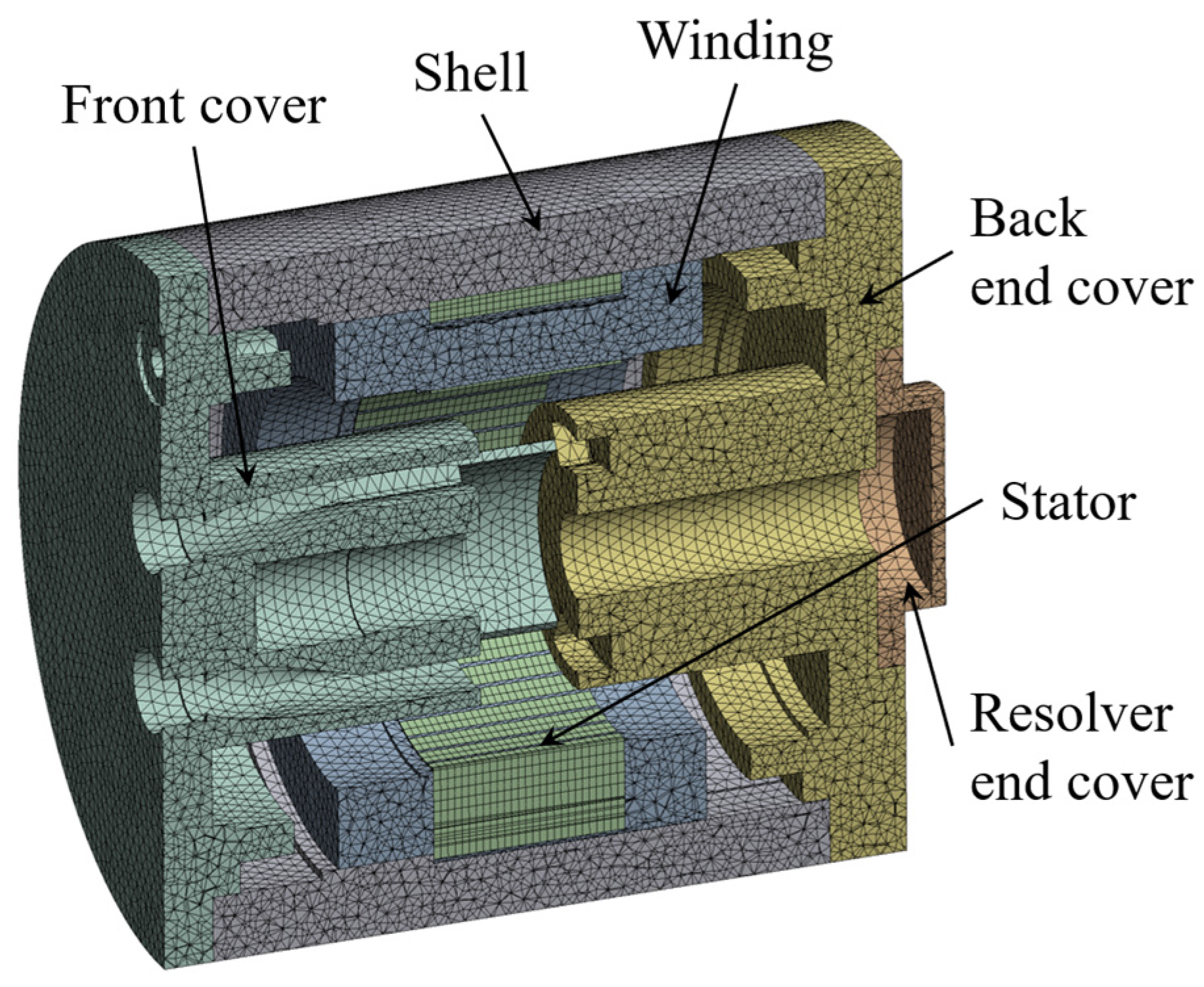
For dry and wet modal comparison modeling, two considerations are taken into account. First, the full EHP assembly contains a large number of components and assembly interfaces, which markedly increases system dissipation and modal coupling. As a result, resonance peaks become less pronounced, reducing the robustness of modal identification. Second, the dominant excitation source for electromagnetic vibration is the electromagnetic force acting on the stator tooth surfaces. This excitation mainly loads the stator and housing and propagates outward through transmission paths such as the end covers. The influence of internal pump components on electromagnetic vibration prediction can therefore be neglected. Accordingly, both the simulations and experiments in this study adopt a “hollow configuration” as the analysis object: internal pump components such as the ring gear and internal gear are removed, while only the primary load-bearing structures are retained and the model is further simplified, as shown in Figure 2. It should be noted that this simplification facilitates a clearer identification of the fluid-induced added-mass effect and its influence on electromagnetic vibration prediction; however, compared with the fully assembled structure, differences still exist in the overall mass distribution, local stiffness characteristics, and actual excitation transmission paths.
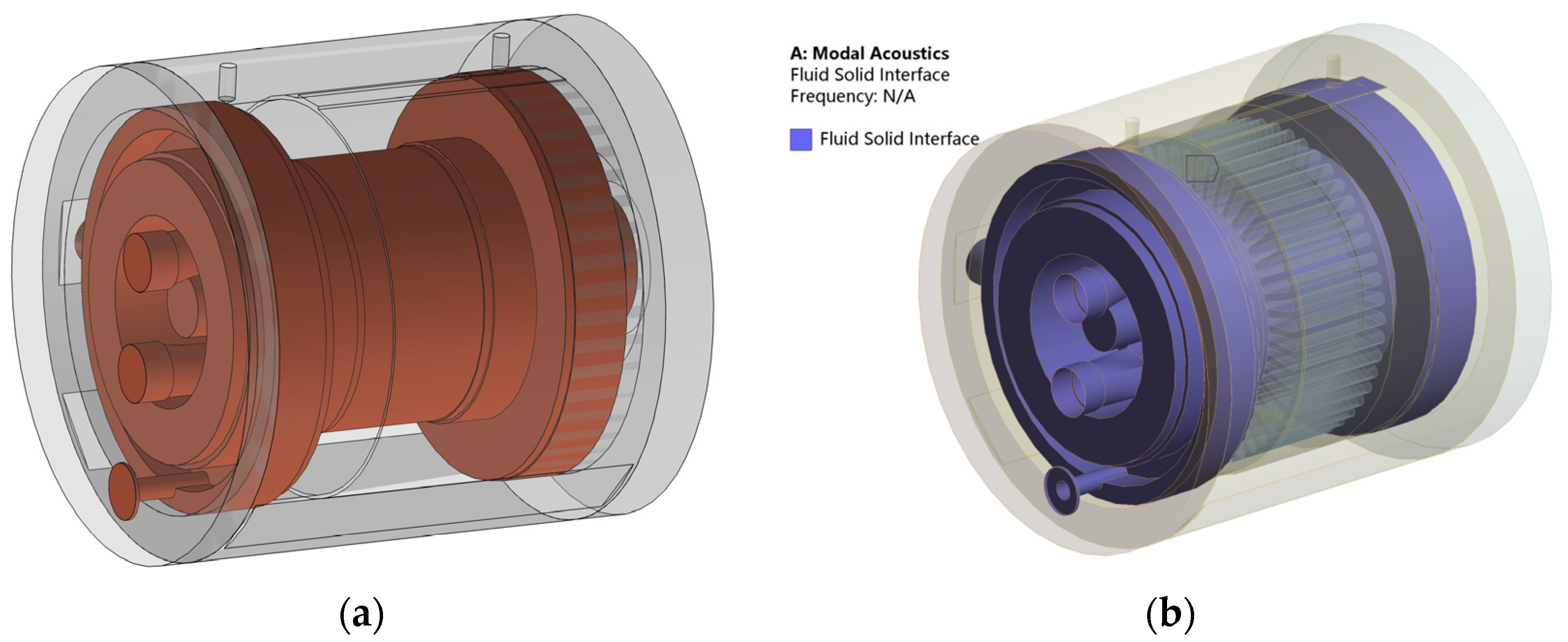
The dry modal analysis involves only the structural domain and is solved using the Modal module in ANSYS Workbench 2023 R2. For the wet modal model, the oil-filled fluid domain inside the hollow structure is extracted and modeled accordingly. The extracted fluid domain is shown in Figure 3a. The boundary between the fluid domain and the solid structure is defined as the fluid–structure coupling interface, as illustrated in Figure 3b, and the wet modal analysis is performed using Modal Acoustics. Since the fluid-induced added mass is generally the principal factor responsible for shifts in natural frequencies, whereas fluid viscous damping has only a limited effect on the modal frequencies themselves and mainly affects response characteristics such as amplitude attenuation and resonance peak broadening, the fluid damping effect is neglected in the present wet modal model to improve computational efficiency. Both dry and wet modal analyses are under free-boundary conditions, and the first nine natural frequencies and mode shapes are extracted. The material properties are set according to the prototype used in the experiments, as listed in Table 2. The hydraulic oil density is taken as 878 kg/m3, and the speed of sound is set to 1430 m/s.

3.2. Dry and Wet Modal Experiments

Figure 4 shows the experimental modal testing setup. The test article also adopts the hollow configuration: components such as the ring-gear rotor and gear shaft are removed from the EHP, and only the primary load-bearing structures are retained. To ensure consistency between the modal tests and the finite-element model, the EHP was suspended by elastic ropes so as to approximate free-boundary conditions as closely as possible. This suspension approach can effectively reduce the influence of external support constraints on the modal characteristics and is commonly used as an approximation of free–free boundary conditions in experimental modal analysis. For the wet modal test, after completion of the dry modal test, the pump was reoriented with the oil ports facing upward, and the internal cavities were completely filled with oil through the ports, which were subsequently sealed to maintain a fully oil-filled condition. Since both the dry and wet modal tests were conducted using the same suspension arrangement and test procedure, any residual support effect mainly acts as a common systematic error, with limited influence on the relative comparison of the modal parameters under the two conditions.
A fixed-response/roving-hammer approach was employed in the modal test. Considering that the tested EHP has an approximately cylindrical geometry, the outer surface of the cylindrical housing was divided into four sections along the axial direction and eight sectors along the circumferential direction, resulting in 32 impact points on the side surface. In addition, five extra measurement points were arranged on the two end faces to improve the characterization of the modal response in the end-cover regions. The distributions of the impact and sensor locations are shown in Figure 4c. For response acquisition, two triaxial accelerometers were mounted at two diametrically opposite positions on the initial axial section of the cylinder in order to capture vibration responses in multiple directions and reduce the risk of missing modal information due to sensor placement near modal nodal regions. An impact-hammer test was performed, and the hammer force and acceleration response signals were acquired synchronously to calculate the frequency response functions. Modal parameters were identified using the PolyMAX method, from which the natural frequencies, damping ratios, and mode shapes were extracted. To improve the comparability of the dry and wet modal tests, the same test equipment, measurement layout, and data-processing procedure were used in both cases. The main factors that may affect the results include the sensor mounting and mass-loading effects, impact consistency, suspension compliance, and environmental noise.

3.3. Modal Results and Discussion

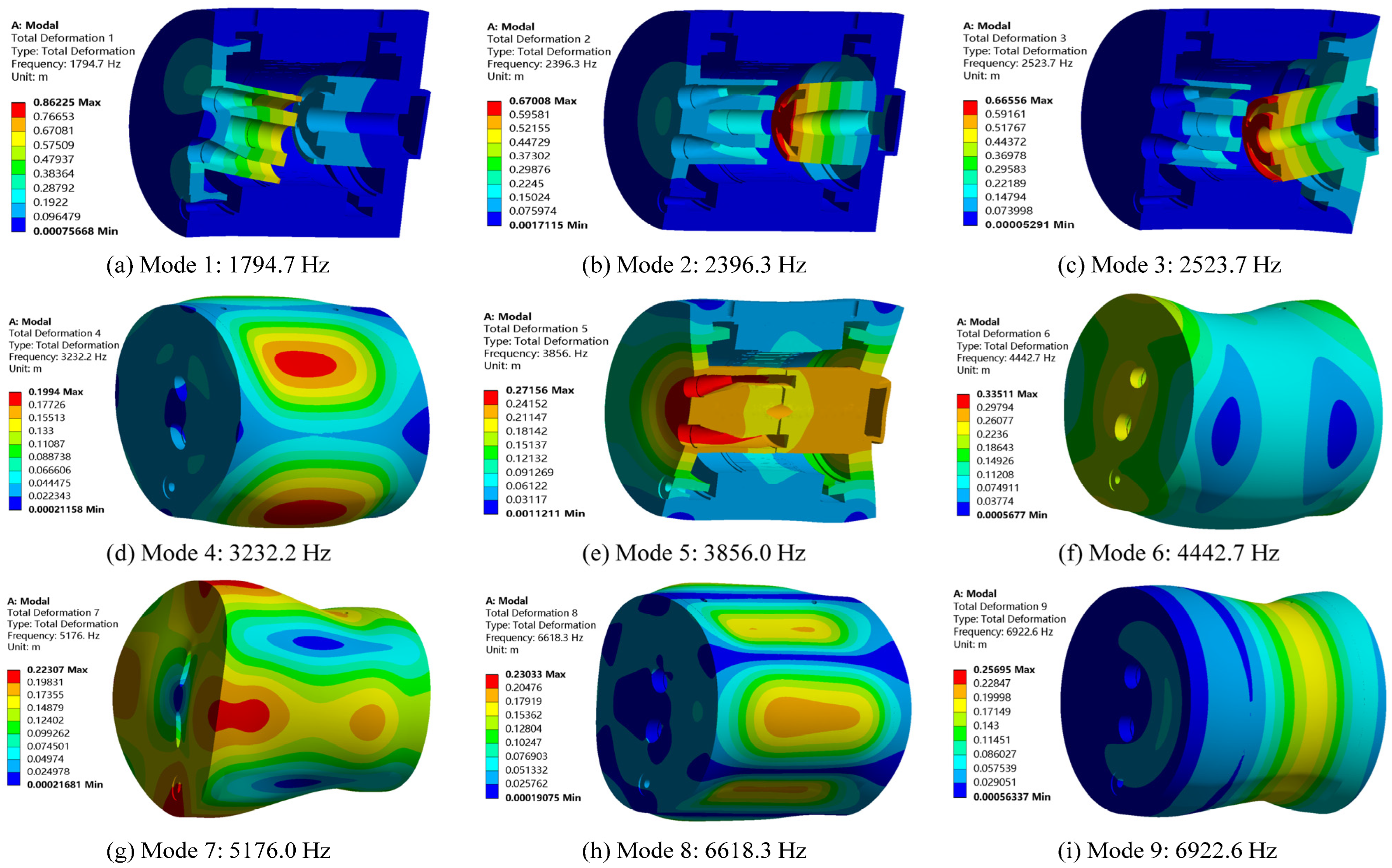
Figure 5 presents the typical mode shapes of the first nine dry modes. It can be observed that the mode shapes are mainly characterized by global bending and torsional deformations of the housing and end covers. The regions with relatively large deformation are primarily concentrated in the end covers, the cylindrical housing, and the transition regions between the housing and the end covers, indicating that these locations are structurally more compliant in a dynamic sense and more sensitive to fluid loading.
Under wet conditions, the identified mode shapes remain essentially consistent with those in the dry case, whereas the natural frequencies exhibit an overall downward shift. This indicates that the oil does not alter the dominant vibration patterns of the structure, but significantly affects the dynamic characteristics of the system. The main reason is that once the internal oil participates in the structural motion a pronounced added-mass effect is introduced, and the natural frequencies are reduced through fluid–structure interaction. The frequency shifts are more significant for the lower-order modes, suggesting that global modes are more susceptible to the influence of the internal fluid.
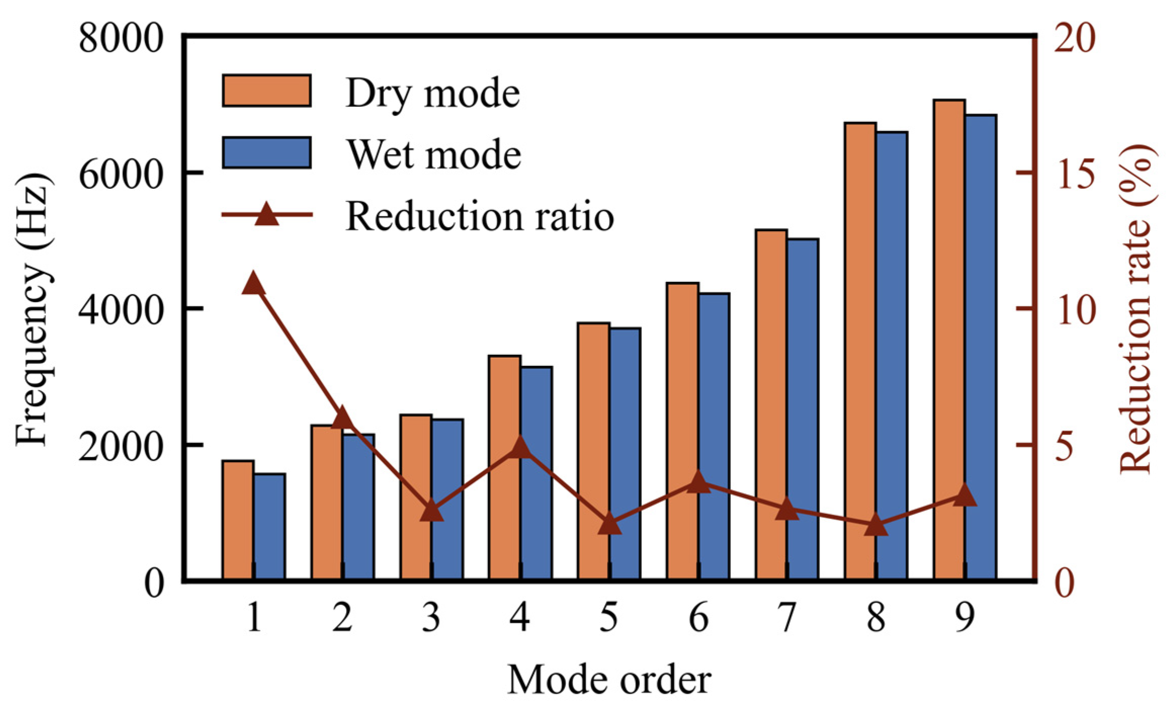
Table 3 summarizes the simulated and experimentally identified natural frequencies for both dry and wet conditions and also reports the relative errors of the simulations with respect to the measurements. The errors for all modes remain within a small range, confirming the accuracy of the proposed numerical models. Figure 6 compares the experimentally obtained natural frequencies versus the mode order for the dry and wet cases. In addition, the frequency reduction ratio of the wet modes relative to the dry modes, η , is defined as
η = f d f w f w × 100 %
As shown in Figure 6, the wet natural frequencies decrease systematically compared with the dry case. The frequency shift is more pronounced for lower-order modes and becomes less significant for higher-order modes. This can be explained as follows: lower-order modes typically involve more global structural motion and higher normal velocities on the inner wall, which entrain a larger effective mass of oil and thus produce a stronger added-mass effect. In contrast, higher-order modes tend to be more localized, with reduced fluid participation in both area and intensity, resulting in smaller frequency shifts.

4. Electromagnetic Vibration Analysis Based on Dry and Wet Modes

4.1. Vibration Simulation

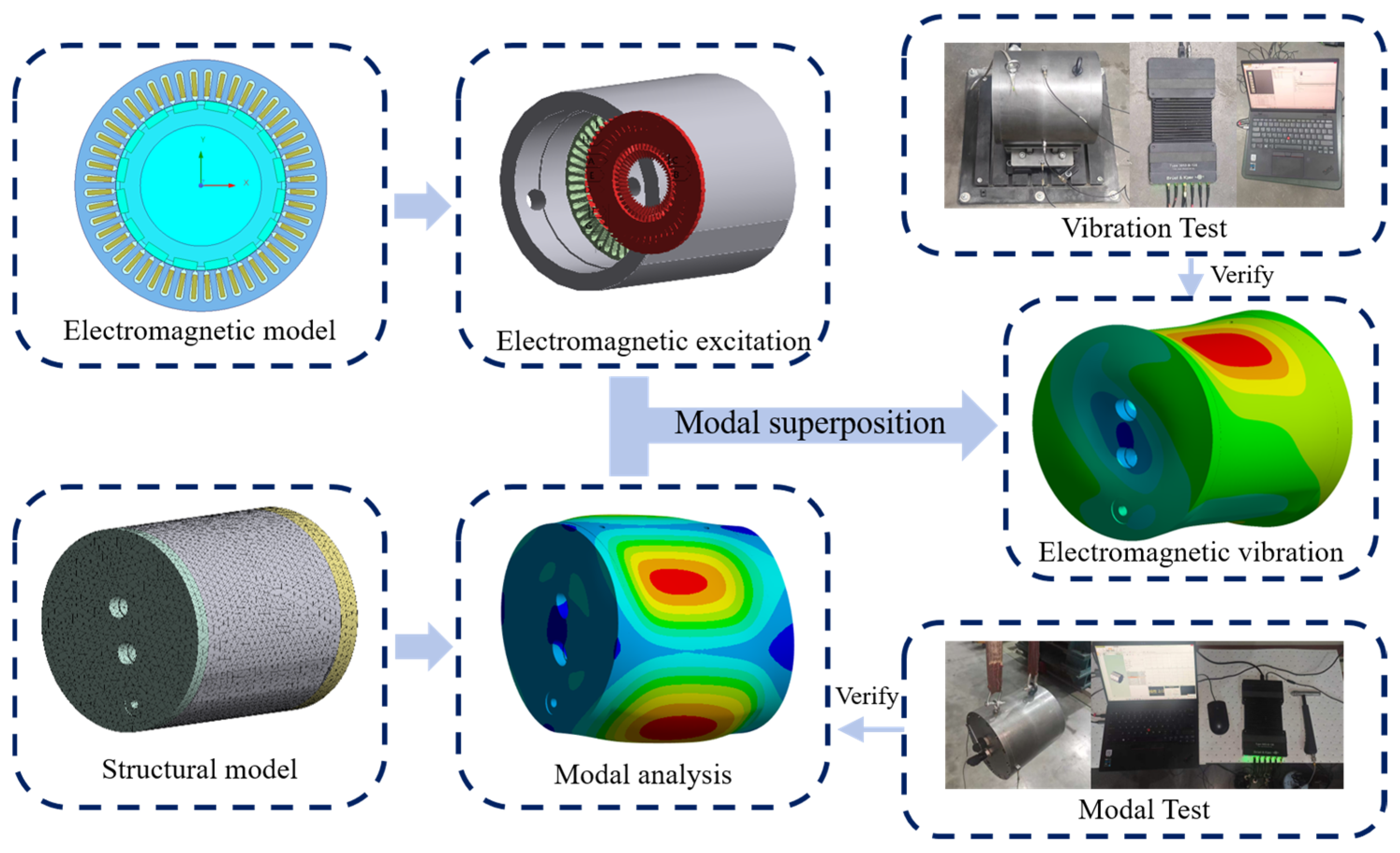
The simulation workflow for electromagnetic vibration of the EHP is shown in Figure 7. First, a two-dimensional electromagnetic field model of the EHP is established to compute the spatiotemporal distribution of the electromagnetic forces acting on the stator tooth surfaces. The obtained electromagnetic forces are then mapped onto the structural model, and the vibration response under electromagnetic excitation is solved using the modal superposition method. Electromagnetic vibration simulations are performed separately using the dry modal and wet modal parameter sets. In the frequency domain, electromagnetic vibration is characterized by prominent discrete spectral lines at the electrical frequency and its harmonics. The electrical frequency is given by
f e = n p 60
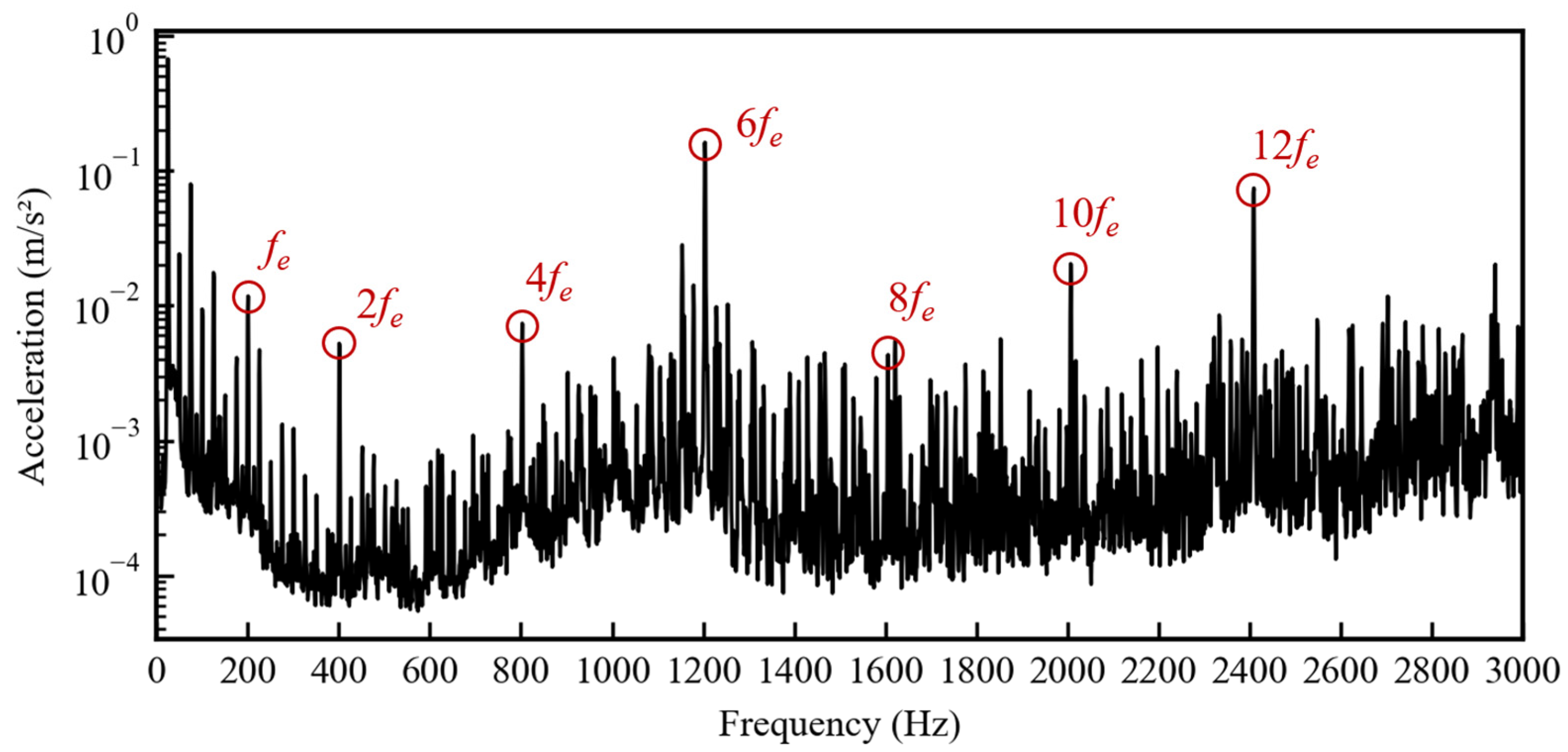
where n is the rotational speed (rpm) and p is the number of pole pairs. In this study, the EHP motor has p = 8 pole pairs and operates at 1500 rpm under no-load conditions. Since the electromagnetic vibration energy is mainly distributed in the low-to-mid frequency range, the vibration response is analyzed primarily within 0–3000 Hz.

4.2. Vibration Experiment

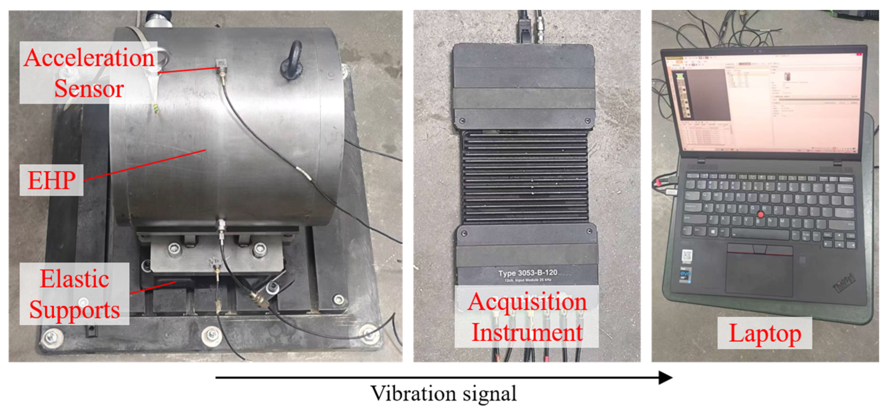
The vibration experiment of the EHP is conducted under the fully oil-filled wet condition. The experimental setup is shown in Figure 8. The motor is connected to a rigid foundation (assumed to have infinitely large stiffness) through an isolator (BE-40) to suppress external vibration disturbances. An accelerometer is mounted on the housing to measure the radial vibration response. The data acquired during the steady-speed stage are selected for FFT-based spectral analysis.
The radial housing acceleration spectrum of the EHP operating at 1500 rpm under no-load conditions is shown in Figure 9. The spectrum indicates that the vibration energy exhibits pronounced discrete line components at the electrical frequency and its even-order harmonics. The frequencies of these spectral peaks are determined by the electromagnetic excitation frequencies, whereas the differences between the dry and wet modal parameters affect the structural response levels at these fixed excitation frequencies through their different representations of the structural dynamic characteristics.

4.3. Electromagnetic Vibration Results and Discussion

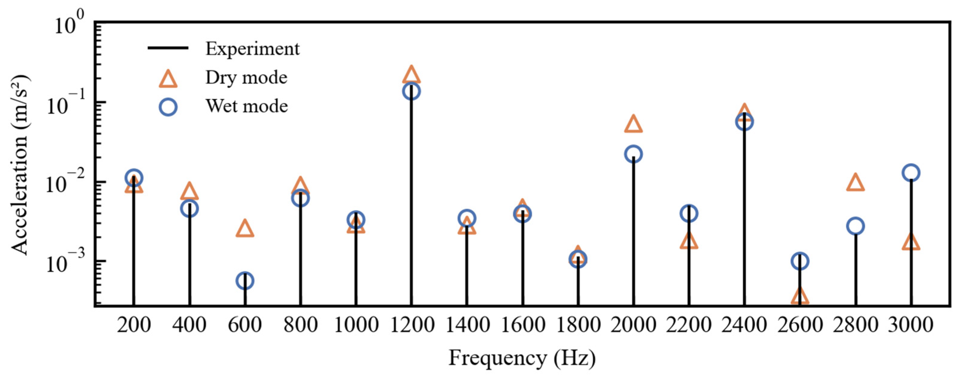
Figure 10 compares the vibration spectra obtained from the dry and wet modal simulations with the experimental results, and the vibration amplitudes and corresponding relative errors at each electromagnetic excitation frequency are listed in Table 4. As shown in Table 4, when the dry modal parameters are used for vibration prediction, the response amplitudes at some frequency points deviate considerably from the experimental results, yielding an average relative error of 78.58%. In contrast, when the wet modal parameters are adopted, the simulated results are in much closer agreement with the experimental data, and the average relative error is reduced to 16.58%. Using the average relative error of response amplitude as the evaluation criterion, the wet modal model improves the vibration prediction accuracy by 78.90% compared with the dry modal model.
A further examination of the error sources indicates that the dry modal model neglects the fluid added-mass effect, which leads to overestimated natural frequencies relative to the actual values. Consequently, the modal participation factors in the modal superposition procedure are distorted, thereby amplifying the predicted response amplitudes under electromagnetic forcing. By contrast, the wet modal model corrects the modal parameters through acoustic–structure coupling, yielding modal frequencies closer to the true oil-immersed condition and thus substantially improving prediction accuracy.

5. Conclusions

This study carried out a systematic numerical and experimental investigation into the dry and wet modal characteristics of an EHP and their influence on the accuracy of electromagnetic vibration prediction. The main conclusions are as follows:
(1)
Compared with the dry case, the wet natural frequencies exhibit a systematic downward shift, with the lower-order modes showing more pronounced frequency reductions. The maximum reduction reaches 10.92%, while the discrepancies between the simulation and experiment are within 6% for all considered modes. This demonstrates that the internal oil has a non-negligible effect on the dynamic characteristics of the EHP, and that the fluid–structure interaction under oil-filled conditions significantly alters the equivalent inertial properties of the system.
(2)
Based on the mode shape distributions, the housing, end covers, and their transition/joint regions are identified as the most vibration-sensitive parts of the EHP. In structural design, these regions should be treated as key targets for dynamic stiffness enhancement and vibration suppression, for example through end-cover thickness optimization, local reinforcement, or improvement of the joint/transition structures.
(3)
Electromagnetic vibration prediction based on the modal superposition method shows that the dry modal simulation yields an average relative error of 78.58%, whereas the wet modal simulation reduces the average relative error to 16.58%, corresponding to a 78.90% improvement in prediction accuracy. This indicates that, for an EHP operating under actual oil-filled conditions, wet modal characteristics can represent the real dynamic behavior more faithfully and are therefore essential for improving electromagnetic vibration prediction accuracy.
(4)
The present results suggest that vibration design and NVH evaluation of EHP pumps should not rely solely on dry structural characteristics, but should preferentially be based on wet modal parameters that are consistent with the actual service condition. This conclusion provides a useful engineering reference for dynamic modeling, resonance risk assessment, and structural optimization design of immersed electromechanical systems.
It should also be noted that the present study is based on a hollowed structural configuration, and the effects of internal rotating components, assembly preload, and the complete assembly condition on modal characteristics were not further considered. In addition, the wet modal analysis was conducted for a static fully oil-filled condition and did not include more complex operating factors such as fluid flow, temperature variation, or viscosity changes. Moreover, the experimental boundary condition was approximated as free–free by elastic-rope suspension, which still differs from the actual installed boundary condition. Therefore, the conclusions of this work are primarily applicable within the structural configuration and operating conditions considered herein. Future work will further incorporate full-assembly coupling effects and realistic service boundary conditions to improve vibration prediction accuracy and support structural optimization design.

Author Contributions

Conceptualization, W.Z. and Z.C.; methodology, X.T.; software, W.Z.; validation, W.Z., X.T. and Z.C.; formal analysis, Y.Z.; investigation, X.T.; resources, X.T. and Z.C.; data curation, W.Z.; writing—original draft preparation, W.Z.; writing—review and editing, W.Z., X.T., Z.C. and Y.Z.; visualization, W.Z.; supervision, Y.Z.; project administration, X.T. and Z.C.; funding acquisition, Z.C. All authors have read and agreed to the published version of the manuscript.

Funding

This research was funded by the foundation of the National Key Laboratory on Ship Vibration and Noise (JCKY2023207CI03), and the Young Elite Scientists Sponsorship Program (2023-xxxx-QT-005).

Institutional Review Board Statement

Not applicable.

Informed Consent Statement

Not applicable.

Data Availability Statement

The data presented in this study are available on request from the corresponding author.

Conflicts of Interest

The authors declare no conflicts of interest.

References

  1. Zhu, D.; Fu, Y.; Han, X.; Li, Z. Design and Experimental Verification on Characteristics of Electro-Hydraulic Pump. Mech. Syst. Signal Process. 2020, 144, 106771. [Google Scholar] [CrossRef] [Scilit]
  2. Zhao, J.; Fu, J.; Li, Y.; Qi, H.; Wang, Y.; Fu, Y. Flow Characteristics of Integrated Motor-Pump Assembly with Phosphate Ester Medium for Aerospace Electro-Hydrostatic Actuators. Chin. J. Aeronaut. 2023, 36, 392–407. [Google Scholar] [CrossRef] [Scilit]
  3. Tan, Y.; Kong, H.; Ma, L.; Xu, C. Testing and Optimization of Noise of an Electrohydraulic Power Steering Pump. J. Braz. Soc. Mech. Sci. Eng. 2021, 43, 407. [Google Scholar] [CrossRef] [Scilit]
  4. Shi, J.; Li, Z.; Gao, J.; Chen, D.; Li, X.; Li, Y.; Zhang, J.; Kong, X. Thermal-Hydraulic Modeling of Oil-Immersed Motor Pump. Appl. Sci. 2023, 13, 9452. [Google Scholar] [CrossRef] [Scilit]
  5. Qiu, X.-G.; Chen, K.-G.; Wu, P.; Zheng, Y.; Wang, C.; Ji, X.-J. Research on the Distribution Structure of 2D Piston Electro-Hydraulic Pump Based on Fluid-Structure Interaction. Adv. Mech. Eng. 2024, 16, 16878132241264985. [Google Scholar] [CrossRef] [Scilit]
  6. Dai, M.; Meng, B.; Tong, C.; Li, S.; Ruan, J. Analytical Modeling and Experimental Validation of the Churning Torque Based on Partial Oil Immersion Wet External Rotor Permanent Magnet BLDC Motor with an Isolation Sleeve. Mech. Syst. Signal Process. 2025, 235, 112882. [Google Scholar] [CrossRef] [Scilit]
  7. Fang, S.; Wei, Y.; Cheng, G.; Liu, Q.; Wu, X. Mechanism and Regularity of Wet Modes in a Highly Integrated Marine Magnetic Levitation Pump Rotor Under Confined Water Conditions. J. Mar. Sci. Eng. 2025, 13, 2400. [Google Scholar] [CrossRef] [Scilit]
  8. Gao, P.; Yu, T.; Zhang, Y.; Wang, J.; Zhai, J. Vibration Analysis and Control Technologies of Hydraulic Pipeline System in Aircraft: A Review. Chin. J. Aeronaut. 2021, 34, 83–114. [Google Scholar] [CrossRef] [Scilit]
  9. Ding, H.; Ji, J.C. Vibration Control of Fluid-Conveying Pipes: A State-of-the-Art Review. Appl. Math. Mech. 2023, 44, 1423–1456. [Google Scholar] [CrossRef] [Scilit]
  10. Tang, Y.; Zhang, H.-J.; Chen, L.-Q.; Ding, Q.; Gao, Q.; Yang, T. Recent Progress on Dynamics and Control of Pipes Conveying Fluid. Nonlinear Dyn. 2025, 113, 6253–6315. [Google Scholar] [CrossRef] [Scilit]
  11. Mikota, G.; Manhartsgruber, B.; Kogler, H.; Hammerle, F. Modal Testing of Hydraulic Pipeline Systems. J. Sound Vib. 2017, 409, 256–273. [Google Scholar] [CrossRef] [Scilit]
  12. Stenius, I.; Fagerberg, L.; Säther, A. Predicting the Natural Frequency of Submerged Structures Using Coupled Solid-Acoustic Finite Element Simulations. Ocean Eng. 2018, 159, 37–46. [Google Scholar] [CrossRef] [Scilit]
  13. Nie, C.; Wang, K.; Mao, Y.; Gao, Q. Efficient Method for Wet Modal Analysis of Cyclic Periodic Fluid/Structure Systems. AIAA J. 2024, 62, 374–385. [Google Scholar] [CrossRef] [Scilit]
  14. Khalfaoui, K.; Moraga, G.; Bareis, J.; Zorn, M.; Presas, A.; Valentín, D.; Riedelbauch, S. On the Numerical Prediction of Added Damping and Added Mass of Vibrating Disc-like Structures in Heavy Fluids. J. Sound Vib. 2025, 618, 119305. [Google Scholar] [CrossRef] [Scilit]
  15. Fiebig, W.; Wróbel, J. Experimental and Numerical Investigation on the Noise Development in Fluid Power Units: An Overview. Arch. Civ. Mech. Eng. 2022, 22, 166. [Google Scholar] [CrossRef] [Scilit]
  16. Castillo, M.A.; Gutiérrez, R.H.R.; Monteiro, U.A.; Minette, R.S.; Vaz, L.A. Modal Parameters Estimation of an Electrical Submersible Pump Installed in a Test Well Using Numerical and Experimental Analysis. Ocean Eng. 2019, 176, 1–7. [Google Scholar] [CrossRef] [Scilit]
  17. Peng, G.; Zhang, Z.; Bai, L. Wet Modal Analyses of Various Length Coaxial Sump Pump Rotors with Acoustic-Solid Coupling. Shock Vib. 2021, 2021, 8823150. [Google Scholar] [CrossRef] [Scilit]
  18. Li, X.; Zhao, S.; Gao, Y.; Chen, J.; Zhang, C.; Qu, Y. Analytical Method for Modal Analysis of Submerged Electric Motor Stator. Ocean Eng. 2023, 276, 114220. [Google Scholar] [CrossRef] [Scilit]
  19. Zhao, J.; Zhang, Q.; Wei, X. An Integrated Approach of a Field-circuit Coupling Model and Multi-physics Finite-Element Simulation for Analysing Transient Electromagnetic Vibration of Pump Motors. IET Electr. Power Appl. 2022, 16, 1030–1056. [Google Scholar] [CrossRef] [Scilit]
  20. Guo, G.; Zhao, Y.; Yu, A. Analysis of Electromagnetic Vibration of Submerged Tubular Linear Motors Based on Wave Propagation Approach. Wave Motion 2024, 127, 103287. [Google Scholar] [CrossRef] [Scilit]
  21. Xu, Y.; Wang, J.; Yang, S.; Lei, G.; Zhao, K. Acoustic Analysis of a Three-Dimensional Cylindrical Shell Model Under Electromagnetic Vibration. Front. Phys. 2024, 12, 1468327. [Google Scholar] [CrossRef] [Scilit]
  22. Chen, Q.; Xie, J.; Xiao, Q.; Lu, L.; Wang, N.; Wang, L. Study on Electromagnetic Vibration of In-Wheel Motor for Electric Vehicle. Int. J. Veh. Noise Vib. 2019, 15, 205. [Google Scholar] [CrossRef] [Scilit]
  23. Ye, S.; Zhang, J.; Xu, B.; Hou, L.; Xiang, J.; Tang, H. A Theoretical Dynamic Model to Study the Vibration Response Characteristics of an Axial Piston Pump. Mech. Syst. Signal Process. 2021, 150, 107237. [Google Scholar] [CrossRef] [Scilit]
  24. Zhang, Y.; Chen, Z.; He, L.; Liao, J.; Zeng, W. Identification of Vibration and Noise Sources in EHA Internal Gear Pumps Under Variable Operating Conditions and Noise Reduction Design. Mech. Syst. Signal Process. 2025, 241, 113558. [Google Scholar] [CrossRef] [Scilit]
  25. Zhou, J.; Jin, G.; Ye, T.; Wang, X. Fluid-Induced Vibration Analysis of Centrifugal Pump Including Rotor System Based on Computational Fluid Dynamics and Computational Structural Dynamics Coupling Approach. Ocean Eng. 2023, 288, 115993. [Google Scholar] [CrossRef] [Scilit]
  26. Pang, H.; Wu, D.; Deng, Y.; Cheng, Q.; Liu, Y. Effect of Working Medium on the Noise and Vibration Characteristics of Water Hydraulic Axial Piston Pump. Appl. Acoust. 2021, 183, 108277. [Google Scholar] [CrossRef] [Scilit]
  27. Cieślicki, R.; Karpenko, M. An Investigation of the Impact of Pump Deformations on Circumferential Gap Height as a Factor Influencing Volumetric Efficiency of External Gear Pumps. Transport 2022, 37, 373–382. [Google Scholar] [CrossRef] [Scilit]
  28. Friedmann, P.P.; Lesieutre, G.A.; Huang, D. Structural Dynamics: Theory and Applications to Aerospace and Mechanical Engineering, 1st ed.; Cambridge University Press: Cambridge, UK, 2023. [Google Scholar]
  29. Urban, O.; Pochylý, F.; Habán, V. Estimation of Added Effects and Their Frequency Dependence in Various Fluid–Structure Interaction Problems. J. Braz. Soc. Mech. Sci. Eng. 2024, 46, 631. [Google Scholar] [CrossRef] [Scilit]
  30. Maurin, A. Numerical Procedure for Investigating the Water-Added Mass Effect on the Vibroacoustic Characteristics of a Cylindrical Container. Adv. Sci. Technol. Res. J. 2025, 19, 80–93. [Google Scholar] [CrossRef] [Scilit]
  31. Ye, W.; Liu, J.; Gan, L.; Wang, H.; Qin, L.; Zang, Q.; Bordas, S.P.A. Fluid-Structure Coupling Analysis in Liquid-Filled Containers Using Scaled Boundary Finite Element Method. Comput. Struct. 2024, 303, 107494. [Google Scholar] [CrossRef] [Scilit]
  32. Oblak, M.; Pirnat, M.; Boltežar, M. Modal-Interaction Approach to the Strong Structural–Acoustic Coupling of an Elastic Helmholtz Resonator and an Acoustic Cavity Containing a Heavy Fluid. J. Sound Vib. 2022, 535, 117120. [Google Scholar] [CrossRef] [Scilit]
Figure 1. Schematic of the EHP structure: (a) sectional view; (b) exploded assembly view.
Applsci 16 03626 g001
Figure 2. Finite-element model of the hollow configuration.
Applsci 16 03626 g002
Figure 3. Wet modal setup: (a) extracted fluid domain; (b) definition of the fluid–structure coupling interface.
Applsci 16 03626 g003
Figure 4. Modal test system: (a) suspended EHP; (b) test equipment; (c) impact and sensor positions.
Applsci 16 03626 g004
Figure 5. Contour plots of dry mode shapes.
Applsci 16 03626 g005
Figure 6. Comparison of dry and wet natural frequencies.
Applsci 16 03626 g006
Figure 7. Workflow of EHP vibration simulation.
Applsci 16 03626 g007
Figure 8. EHP vibration experiment.
Applsci 16 03626 g008
Figure 9. Acceleration spectrum of EHP vibration.
Applsci 16 03626 g009
Figure 10. Comparison between dry/wet modal simulations and experiments for electromagnetic vibration.
Applsci 16 03626 g010
Table 1. Main dimensions and performance parameters of the EHP.
ParameterValueParameterValue
Dimensions (mm)287 × 313 × 266Stator outer diameter (mm)210
Number of teeth17/14Number of slots/poles48/16
Maximum pressure (MPa)15Displacement (cm3/rev)35
Rated power (kW)11Rated speed (rpm)1500
Table 2. Material properties.
ComponentMaterialsDensity (kg/m3)Elastic Modulus (GPa)Poisson Ratio
Shell, front cover, back end coverQT40072001600.27
WindingCopper89301120.34
Resolver end cover#4578502050.3
StatorSilicon steel75002000.29
Table 3. Simulated and experimental natural frequencies of dry and wet modes.
ModeDry Modal Frequencies (Hz)Wet Modal Frequencies (Hz)Reduction
Ratio
SimulationExperimentRelative ErrorSimulationExperimentRelative Error
11794.71760.71.93%1571.41568.50.19%10.92%
22396.32278.55.17%2252.82142.05.17%5.99%
32523.72428.63.92%2255.92365.5−4.64%2.60%
43232.23294.5−1.89%3207.83133.22.38%4.90%
53856.03784.81.88%3658.43704.6−1.25%2.12%
64442.74371.01.64%4257.04213.01.04%3.62%
75176.05145.90.58%5096.45009.91.73%2.64%
86618.36722.5−1.55%6475.66584.2−1.65%2.06%
96922.67054.2−1.87%6676.46832.1−2.28%3.15%
Table 4. Comparison between simulated and measured electromagnetic vibration and relative error.
Frequency (Hz)Measured Vibration (mm/s2)Dry ModeWet Mode
Vibration (mm/s2)Relative ErrorVibration (mm/s2)Relative Error
20011.769.31−20.83%11.04−6.18%
4005.247.6445.73%4.55−13.24%
6000.702.60272.65%0.56−19.65%
8007.388.9321.06%6.16−16.49%
10004.092.90−29.21%3.28−19.94%
1200162.05224.0838.28%136.20−15.95%
14002.742.812.51%3.4224.81%
16004.334.677.96%3.89−9.99%
18001.131.217.06%1.05−7.43%
200020.4353.60162.32%22.017.73%
22004.931.84−62.66%3.94−20.08%
240074.2074.220.02%56.15−24.33%
26001.200.37−69.07%0.99−17.69%
28002.169.85355.80%2.7326.54%
300010.791.78−83.52%12.8018.63%
Disclaimer/Publisher’s Note: The statements, opinions and data contained in all publications are solely those of the individual author(s) and contributor(s) and not of MDPI and/or the editor(s). MDPI and/or the editor(s) disclaim responsibility for any injury to people or property resulting from any ideas, methods, instructions or products referred to in the content.