1. Introduction
Long-term safety assessment of deep geological repositories for spent nuclear fuel must explicitly account for the persistent thermal load generated by radioactive decay. Although decay heat decreases with time, spent nuclear fuel remains a heat source over several thousands of years, inducing a prolonged thermo-mechanical (TM) perturbation of the engineered barriers and the surrounding host rock. Heat conduction from emplaced canisters leads to temperature increases in the near field, thermally induced rock expansion, stress redistribution, and time-dependent deformation of pre-existing fractures. These coupled processes are fundamental components of post-closure repository evolution and are therefore central to safety assessment frameworks for crystalline rock repositories (e.g., [
1,
2]).
In crystalline rock settings, a safety-relevant low-probability scenario concerns the shear reactivation of fractures intersecting deposition holes. Thermally induced stress changes may alter the balance between normal and shear loading acting on critically oriented fractures, potentially triggering slip. Within the Swedish KBS-3 vertical disposal concept, shear displacement along a fracture intersecting a deposition hole exceeding a design threshold on the order of centimetres (commonly cited as approximately 5 cm, [
3,
4]) is considered capable of compromising canister integrity, thereby increasing the possibility of radionuclide release from the repository [
2,
5]. Although such a scenario is unlikely, its potentially severe consequences require quantitative and mechanistic evaluation as part of the safety case.
Assessing thermally induced fracture slip over repository timescales presents significant modelling challenges. Continuum-based thermo-elastic or thermo-elasto-plastic approaches are effective for describing large-scale stress redistribution and temperature evolution but have limited capability to explicitly represent fracture networks and discontinuous deformation processes, particularly when slip localization and interaction between fractures are important [
6]. Discrete element methods (DEM), by contrast, provide a natural framework for simulating fracture-controlled rock mass behaviour, including stick–slip response, mobilization of frictional resistance, and mechanical interaction within complex discrete fracture networks (DFNs) [
7,
8]. When combined with time-dependent thermal loading, DEM offers a powerful tool for investigating the long-term mechanical response of fractured crystalline rock surrounding a geological repository.
In this study, we apply a three-dimensional discrete element modelling framework to investigate the thermally induced stress evolution and long-term deformation of a DFN representative of the host rock of the spent nuclear fuel repository at Forsmark, Sweden. The Forsmark site, selected by the Swedish Nuclear Fuel and Waste Management Company (SKB), is characterized by crystalline bedrock with a well-documented fracture system and has been extensively analyzed within the Swedish safety case [
2]. In the present paper, simulations of the Forsmark repository are performed independently from SKB’s work using Particle Flow Code in three dimensions (PFC3D), which allows explicit representation of fractures embedded in a bonded particle assembly and enables fracture slip to emerge naturally from contact-scale mechanics [
9].
The modelling focuses on the post-closure phase of the repository and captures the long-term thermal evolution of the host rock driven by decay heat from spent nuclear fuel. Time-dependent temperature fields are imposed onto the repository to represent heating and subsequent cooling of the spent fuel, and the resulting thermo-mechanical response of the DFN is analyzed. Particular attention is given to fractures intersecting deposition holes, as these are the most critical locations from a canister-integrity perspective.
The objectives of this paper are twofold. First, it aims to reproduce the long-term thermal evolution of the Forsmark repository host rock following canister emplacement and repository closure. Second, it seeks to quantify the magnitude and temporal development of fracture shear slip and to assess these responses against the repository safety design limits set up by SKB for the Swedish safety case.
2. Thermo-Mechanical DEM Modelling Using PFC3D
2.1. Recent Progress in TM Modelling of Fractured Rock Relevant to DEM-Based Fracture Slip Analysis
Recent studies on coupled thermo-hydro-mechanical (THM) behaviour in fractured rock have shown that the choice of modelling framework strongly influences how fracture deformation, stress redistribution, and permeability evolution are represented. This issue is particularly important for crystalline rock repositories, where thermally induced fracture slip is controlled not only by the large-scale temperature and stress field, but also by fracture geometry, network connectivity, local contact conditions, and frictional interaction along pre-existing discontinuities. In this context, continuum, discontinuum, and hybrid formulations have each been developed for different scales and objectives, but no single approach is universally suitable for all fractured-rock THM problems.
A substantial body of work has focused on DFN-based representation of fractured rock masses. Hadgu et al. [
10] compared discrete fracture network (DFN) and equivalent continuum approaches for flow and transport in the far field of a hypothetical crystalline-rock nuclear waste repository, showing that both can be useful, depending on the required level of structural detail and the processes of interest. De Simone et al. [
11] proposed a simplified semi-analytical method to estimate thermally induced rock deformation and associated fracture-aperture changes in stochastic DFN systems. Related DFN studies by Davy et al. [
12], Gottron and Henk [
13], and De Simone et al. [
14] further demonstrated the value of explicit fracture-network approaches for hydro-mechanical characterization of anisotropic fractured rock masses. These studies illustrate the continuing balance between explicit fracture representation and continuum simplification in repository-relevant modelling.
A more explicitly geomechanical branch of DFN research has emphasized the role of fracture interaction, stress heterogeneity, and network connectivity in controlling slip and permeability evolution. Lei and Gao [
15] showed that local stress perturbation increases with local fracture intensity and that strongly connected networks can generate pronounced stress dispersion under critically stressed conditions. Thomas et al. [
16] used a finite-element-based fracture mechanics approach to generate dense three-dimensional geomechanical DFNs and demonstrated that fracture interaction can lead to highly intersected and anisotropic network structures. Lei et al. [
17] reported that the geometrical connectivity of fracture systems exerts a first-order control on frictional sliding, dilation, and permeability enhancement, while Paluszny et al. [
18] showed that mechanical interaction between fractures significantly affects nucleation, intersection behaviour, aperture distribution, and effective permeability in geomechanically generated networks. Lei et al. [
19] extended this line of work by developing a fully coupled framework that includes activation of pre-existing fractures, propagation of new damage, induced seismicity, and evolving connectivity, and found that well-connected systems tend to generate more induced seismicity but less connectivity enhancement than poorly connected ones. Ringel et al. [
20] applied stochastic inversion to infer structural and hydraulic properties of a highly fractured zone at Grimsel, and Lei and Tsang [
21] analyzed injection-induced deformation and seismicity in a mature fault zone, highlighting the strong influence of in situ stress, fracture orientation, fracture distribution, and injection-point location. These studies show that fracture reactivation and permeability evolution cannot be evaluated reliably without considering explicit fracture-network geometry and mechanical interaction.
In parallel, a number of hybrid approaches have been developed to combine the geometric flexibility of discrete-fracture representation with the computational efficiency of continuum formulations. Wang et al. [
22] showed that the embedded discrete fracture model (EDFM) provides a computationally efficient alternative to intensive local mesh refinement for fracture-dominated flow and heat transport. Li et al. [
23] applied EDFM together with XFEM to simulate THM coupling in enhanced geothermal systems, Tran and Jha [
24] used EDFM for coupled flow, solute transport, induced stress, and fracture-mechanics analysis, and Zhang et al. [
25] proposed a fully THMC-coupled EDFM–XFEM framework for heat extraction in fractured reservoirs. These developments demonstrate that hybrid methods can substantially improve computational tractability, although they still require modelling choices regarding which fractures are represented explicitly and which are incorporated into an upscaled matrix domain.
For the present study, however, the most relevant developments are those concerned with microscale contact mechanics and discontinuous fracture deformation. Thermally induced fracture slip is fundamentally governed by local changes in normal and shear force, contact opening and closure, frictional mobilization, and asperity interaction along rough fracture surfaces. Hu and Rutqvist [
26,
27] addressed this problem by developing a rigorous microscale contact framework for deformable geomaterials with dynamic contacts, including multi-step contact calculations suited to evolving fracture interaction. This type of formulation is directly relevant to rough-fracture thermos-mechanics because it treats deformation as a sequence of contact-state changes rather than as a purely continuum stress response.
Related developments in grain-based and discontinuum modelling further support this perspective. Lan et al. [
28], Ghazvinian et al. [
29], and Wang et al. [
30] used grain-based discrete element models to simulate fracture initiation and propagation in rock. Park et al. [
31] showed that accurate analysis of rough-fracture contact and shear behaviour requires very high element resolution in order to capture geometry and contact evolution adequately, underscoring the computational demands of high-fidelity discontinuum modelling. Sasaki and Hu [
32] demonstrated that FLAC3D, with enhanced contact-calculation capability, can also be applied to the shearing of single rough fractures, while Wu et al. [
33] developed a two-dimensional FDEM-based THM coupling framework for deformation and fracturing in rock masses, illustrating the continuing evolution of mixed continuous–discontinuous methods.
Overall, the recent literature supports three key observations that motivate the present modelling strategy. First, DFN-scale studies consistently show that fracture connectivity, network interaction, and stress heterogeneity exert strong control on slip, dilation, and permeability development. Second, hybrid continuum–discontinuum methods can improve efficiency, but they still rely on simplifications in the treatment and partitioning of fracture systems. Third, when the principal quantity of interest is the local thermo-mechanical reactivation of pre-existing fractures, especially where roughness-controlled contact evolution is important, a discontinuum framework remains particularly advantageous because it can represent transitions among bonded, sliding, and open contact states directly. For this reason, the present study adopts a thermo-mechanically coupled DEM framework using PFC3D [
34].
2.2. Thermo-Mechanical Coupling in PFC3D
In the mathematical model of thermal evolution in PFC3D [
34], the time evolution of the temperature and the heat flux vector is calculated throughout the rock mass. The continuity equation and transport laws, derived from Fourier’s law of heat conduction, are the governing equations that relate these two variables. When assuming that strain changes contribute negligibly to the temperature, which is a valid assumption for quasi-static mechanical problems involving solids and liquids, heat conduction can be expressed by:
where
is the heat flux vector (in W/m
2),
is the volumetric heat source intensity (in W/m
3),
is the mass density (in kg/m
3),
is the specific heat at constant volume (in J/kg°C), and
is the temperature (in °C). The relation between the heat flux vector and the temperature gradient is defined through Fourier’s law for a continuum as:
where
is the thermal conductivity tensor (W/(mK)).
The four micro-properties used by PFC to simulate temperature and heat flux evolution are: density
(kg/m
3), specific heat at constant volume
(J/kgK), linear thermal expansion coefficient
(in 1/°C), and thermal resistance per unit length
(K/Wm). Thermal resistance of each pipe
is back-calculated from the thermal conductivity
(assumed thermally isotropic) by:
Along with these properties, temperatures are assigned to thermal balls to establish boundary and initial model conditions. By default, the physical boundaries of the particle assembly are adiabatic; that is, no heat flows out of the boundary of the pipe network.
In PFC, each particle in thermal material is represented as a heat reservoir, forming a heat reservoir network bonded by thermal contacts, which are associated with mechanical contacts. Thus, heat flow occurs through conduction in active thermal contacts that connect the heat reservoirs. Each particle, or heat reservoir, has an associated temperature, mass, volume, specific heat, and linear thermal expansion coefficient. During the thermal simulation, the temperature of each particle is computed. If the host mechanical contact associated with a particle is active, the thermal contact is also considered active, allowing for heat flow between adjacent particles, representing heat diffusion from radioactive waste storage in the context of the PFC3D rough fracture model. The thermal contact model updates the power associated with each thermal contact, based on the temperatures in the two connected particles. In this study, the thermal pipe contact model was used, which defines three properties subject to modification: thermal resistance , linear thermal expansion coefficient , and temperature . The length of the thermal contact is defined as the distance between the centroids of the two connected particles. It should be noted that in PFC3D, it is assumed that one or more mechanical sub-steps could be taken after each thermal step, during which time the thermal time is not incremented.
3. 3D Forsmark Repository Model
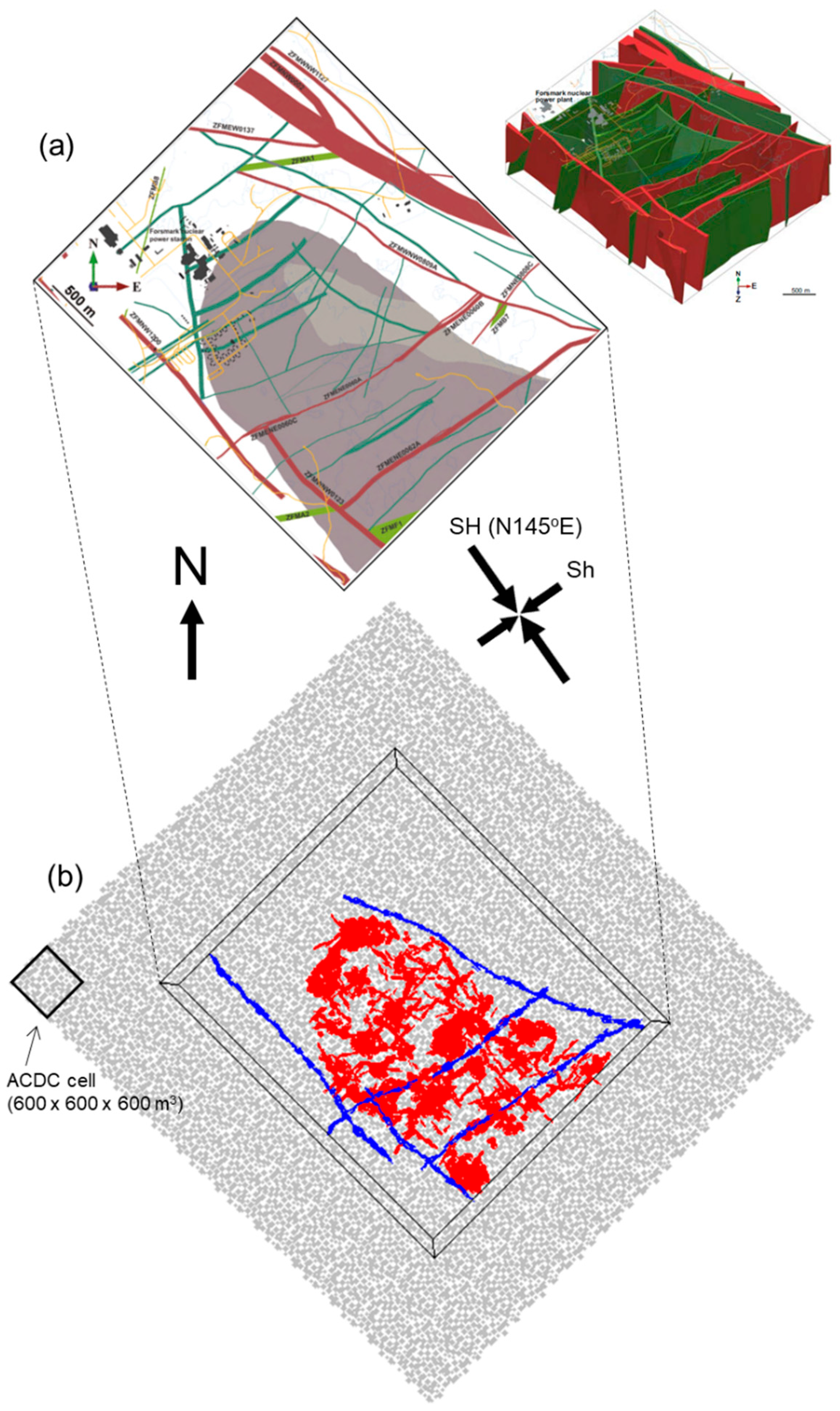
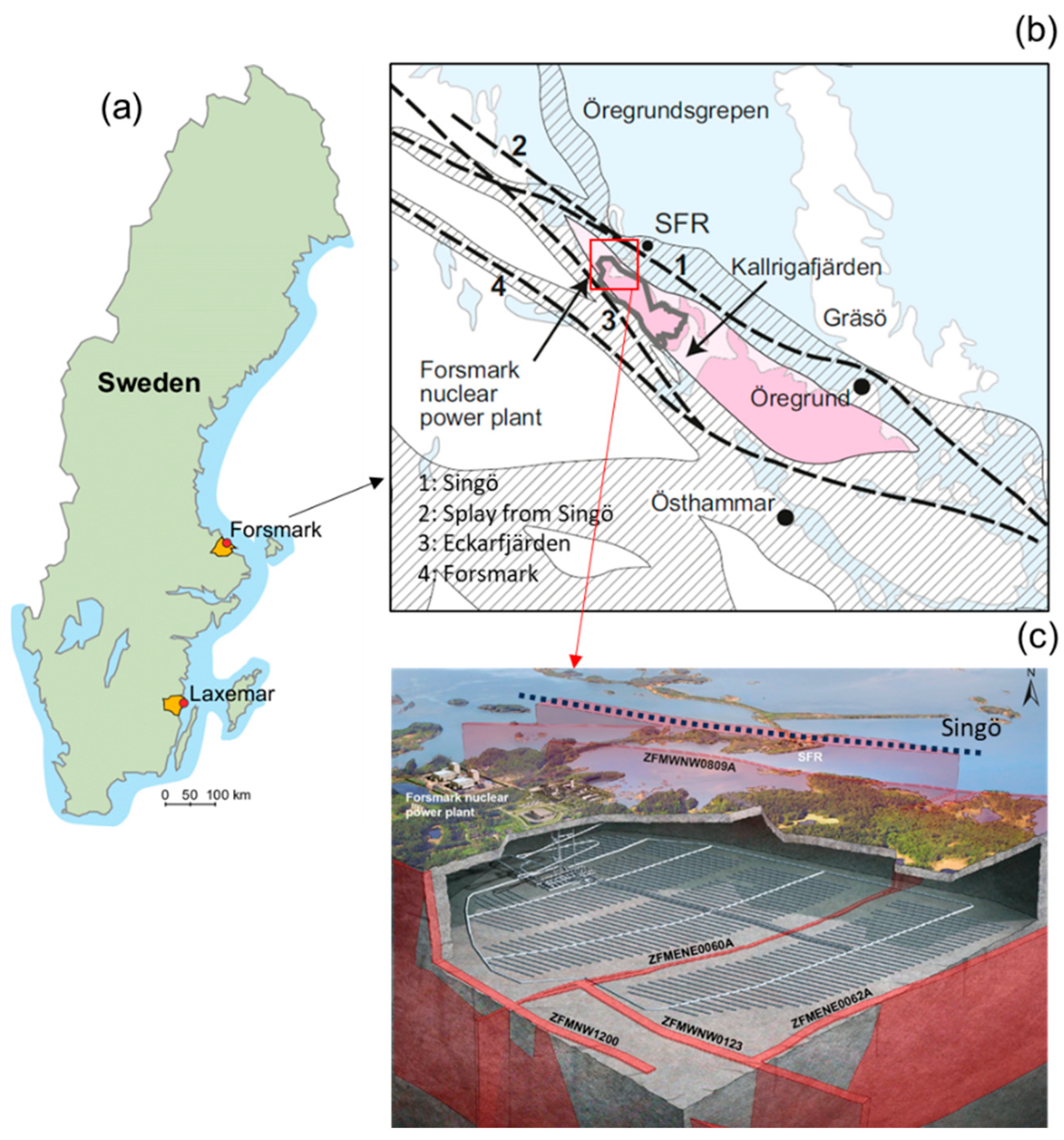
The planned repository layout is bounded and intersected by several major deformation zones that define the structural framework of the site (
Figure 1). The discrete element models of the Forsmark repository site are constructed on the basis of the integrated geological model of the Swedish Nuclear Fuel and Waste Management Company (
Figure 2) developed for the Forsmark area by Stephens et al. [
35], which synthesizes geological mapping, geophysical surveys, and borehole investigations. The geological framework adopted here focuses on the repository horizon at approximately 460 m depth, corresponding to the planned depth of waste emplacement within the Local Model Volume (LMV) defined by SKB. At this depth, the geological structure is dominated by a network of brittle deformation zones and associated fracture domains. The bedrock in the Forsmark area has undergone multiple, distinct episodes of deformation, characterized by early ductile structures overprinted by brittle deformation. The deformation zones are classified according to their dip and surface trace length. Steeply dipping or near-vertical deformation zones with surface trace lengths exceeding 3000 m are distinguished from shorter steep zones with surface trace lengths less than 3000 m, while a separate group of zones consists of gently dipping deformation zones. These structures represent the largest-scale discontinuities in the Forsmark bedrock and play a key role in repository layout design and safety assessment (
Table 1).
Generation of a large three-dimensional models with densely packed particles for the discrete element model (DEM, Cundall & Strack [
7]) based Particle Flow Code 3D (PFC3D, [
34]) numerical simulations requires several hundreds of thousands of particles and entails high computational cost. To make the simulations computationally feasible, an Adaptive Continuum–Discontinuum (AC/DC) approach is employed to construct the three-dimensional geological models of the Forsmark repository site. This approach allows efficient representation of large rock volumes while retaining discrete resolution in regions of interest and has been applied successfully in previous studies (e.g., [
36]). The particle diameters range between 50 m and 80 m, and in total, 421,616 particles are used to densely pack the entire model with 6600 m × 6000 m × 2400 m.
Following the generation of the particle assembly, geological discontinuities including deformation zones and repository-scale fracture systems are explicitly embedded in the integrated geological model. The Local Scale Model (LSM) includes the layout-determining deformation zones, as these structures directly influence the geometry and positioning of waste emplacement panels. The geometrical descriptions of these zones are extracted from SKB’s deterministic fault models and converted into a form suitable for implementation within the discrete element framework (
Figure 2).
The geological discontinuities (i.e., deformation zones and fracture systems) are represented in the discrete element models using the “smooth joint contact formulation” (Mas Ivars et al. [
37]) which enables realistic simulation of frictional slip and separation along predefined discontinuities described by arrangements of particles. This approach is particularly well suited for analyzing shear reactivation and slip localization along fractures under evolving stress conditions.
In this study, deformation zones embedded in the LSM are referred to as layout-determining deformation zones, reflecting their direct influence on repository geometry and deposition panel design. The deformation zones included here are summarized in
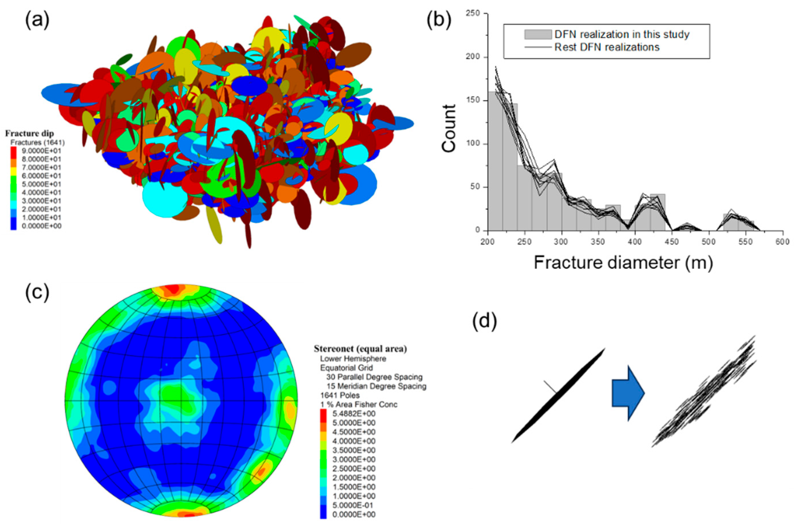
Table 1. The geometry of natural pre-existing fractures embedded in the repository rock mass are implemented in the model as Discrete Fracture Network (DFN). The planar disc DFN (
Figure 3a) is stochastically generated within the repository rock volume (bounding box in
Figure 2b). It should be noted that, in the present study, only one DFN realization was selected out of a total of ten generated realizations. The statistical characteristics of the fracture network, including length and orientation distributions, are presented in
Figure 3b,c. Although the analysis focuses on a single realization, a comparison of the diameter distributions across all ten realizations shows that the selected DFN exhibits statistical properties that are consistent with the ensemble. The fractures are created and input as planar discs (
Figure 3a). However, unlike in other modelling codes (e.g., 3DEC in [
3]), when a planar fracture is embedded in a PFC-generated discrete element model, the fracture is represented by a collection of smooth joints constituted by particles (Mas Ivars et al. [
37]) as shown in
Figure 3d. In such case, the particle in the smooth joints overlap one another. Due to this irregular structural feature, smooth joint contact properties are adjusted using the calibration method in Yoon & Zang [
9]. This results in a more realistic approach of fracture ligaments. Compared to simple planar discontinuities (UDEC, 3DEC), the en-échelon structure of the smooth joint approach (PFC) encounters a finite fracture damage zone which is segmented, and therefore, acts different in shear when compared with discontinuities represented by two planar planes. The resulting parameters for smooth joint contacts in the model are listed in
Table 2. The thermal properties of the repository rock mass are given in
Table 3. Unlike the fracture properties (
Table 2), thermal properties are given directly to the model without calibration.
The planned spent nuclear fuel repository at Forsmark is based on the Swedish KBS-3 vertical disposal concept, developed by the SKB. The repository is designed to accommodate about 6000 spent fuel canisters emplaced at a depth of 460 m.
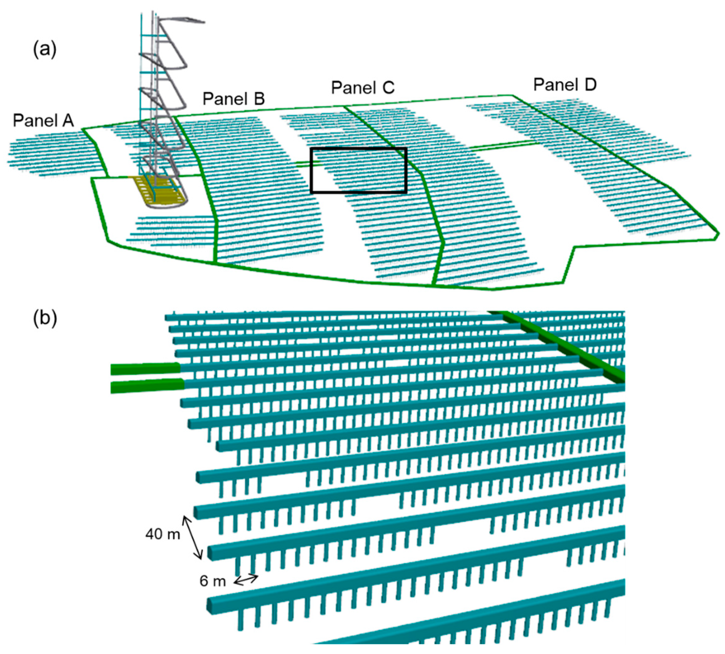
As illustrated in
Figure 4, the underground facility is subdivided into several deposition panels (denoted Panels A–D,
Figure 4a). In the panels, each deposition tunnel accommodates vertical deposition holes drilled into the tunnel floor at regular intervals (
Figure 4b). Spent nuclear fuel canisters are emplaced individually in these holes and surrounded by compacted bentonite buffer blocks. The deposition tunnels are subsequently backfilled and sealed after completed emplacement. The spacing between deposition holes and between adjacent tunnels is a key design parameter and is selected to manage the cumulative thermal load from decay heat, ensuring that peak temperatures in the buffer remain below design limits.
A fundamental design principle for the Forsmark repository is the avoidance of large fractures intersecting deposition holes, as well as maintaining defined respect distances to major deformation zones. The latter are treated deterministically and excluded from the repository footprint or crossed only by non-emplacement tunnels where unavoidable. As a result, deposition tunnels are preferentially located within rock volume characterized by relatively low fracture frequency and favourable rock mechanical properties. Nonetheless, smaller-scale fractures are ubiquitous in crystalline rock and inevitably intersect some deposition holes.
4. Simulation of Heat Loading
The heat generated by spent nuclear fuel canisters constitutes the primary long-term driving force for thermo-mechanical processes in the repository host rock and its fracture system. In the modelling framework adopted here, the temporal evolution and spatial distribution of this heat source are represented in a manner consistent with the repository layout and the three-dimensional nature of the problem. In the simulations, the canister thermal power curve in Hökmark et al. [
1] is used. The time-dependent heat input is expressed as a decay function:
where
is the initial heat power of a canister (1700 W) and
describes radioactive decay. The parameters (
,
) defining the decay function are taken from Hökmark et al. [
1], ensuring consistency with established thermal analyses for the Swedish KBS-3 vertical disposal concept in the repository Safety Assessment [
1] and Safety Case SR-Site [
2].
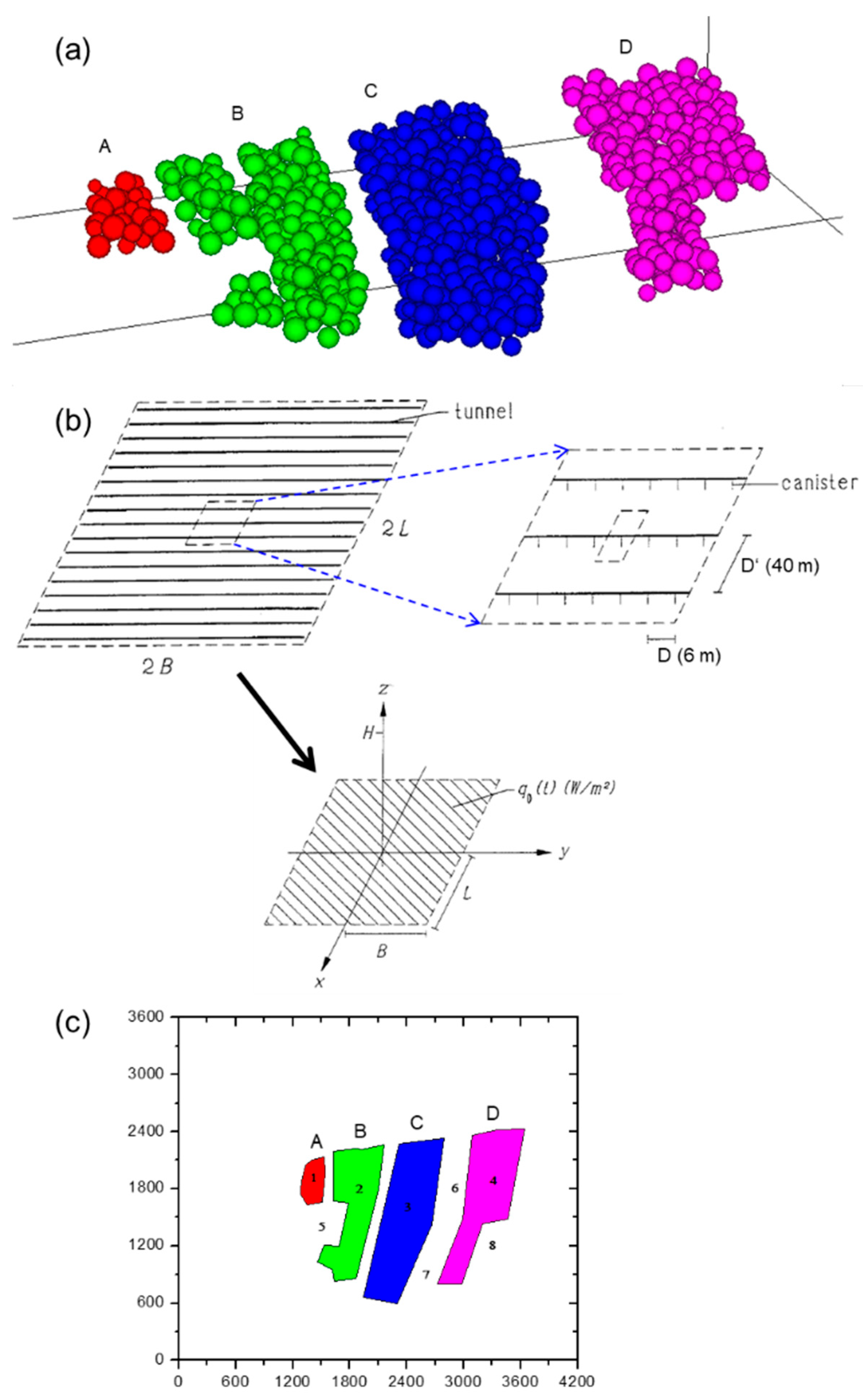
Heat generation is modelled by thermal flux assigned to groups of particles representing the panels (
Figure 5a). We assumed that the panels are plane heat sources in which the canisters are distributed uniformly with the spacing between deposition holes in a tunnel (
= 6 m) and the spacing between deposition tunnels (
= 40 m). The heat input is therefore defined as a heat flux,
(W/m
2), rather than as discrete point power sources, following approaches like those proposed by Claesson and Probert [
38] and Probert and Claesson [
39], see
Figure 5b.
To verify the calibration of the heat-loading implementation, a thermal-only benchmark simulation (i.e., without coupling to mechanical deformations) is performed in which all panels are heated simultaneously. The resulting temperature increase within the repository host rock is evaluated at representative times, notably at 50 years and 200 years after the onset of heat release. The simulated temperature changes are found to be comparable with those reported by Hökmark et al. [
1], who obtained for example a maximum temperature increases of approximately 24–28 °C at 50 years and 20–24 °C at 200 years at the centre of Panel A. We also implemented several temperature monitoring locations as shown in
Figure 5c to later comparison of temperature evolutions between two heating scenarios.
5. Modelling of the Repository Heating Scenario
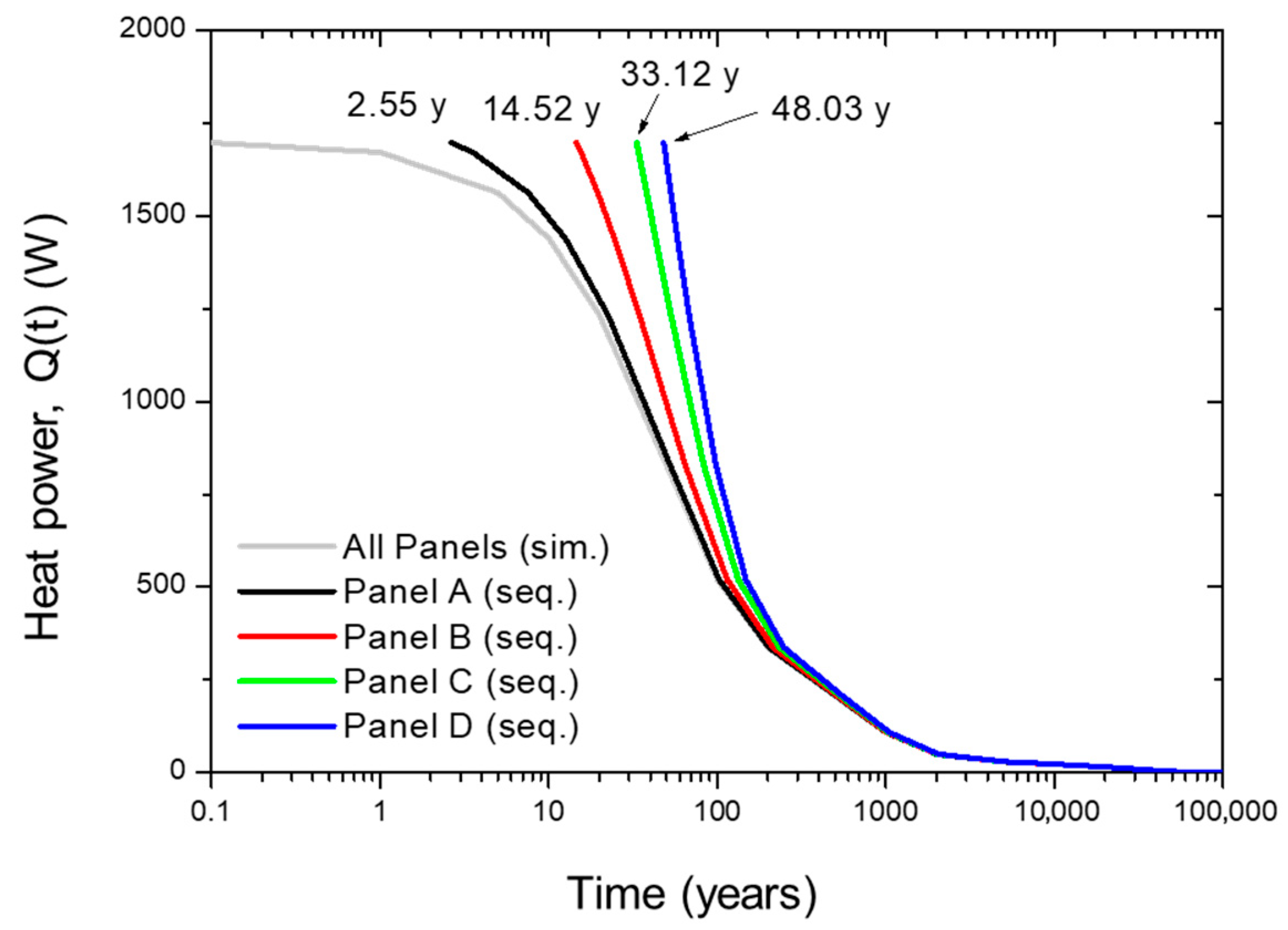
In this section, two thermo-mechanical (TM) modelling analysis cases are investigated to examine the temporal evolution of temperature in the repository host rock and the associated development of shear slip along fractures induced by decay heat from spent nuclear fuel. The first analysis case considers an all-panels simultaneous heating scenario, in which all canisters are emplaced and the repository is closed at the same time, which means that heat release from all deposition holes begins simultaneously. The second analysis case considers a sequential panel heating scenario, in which canister emplacement and heat release proceed panel by panel. In the simultaneous heating scenario, the decay heat power
(grey curve in
Figure 6) is applied to all repository panels at the same time. Although this scenario does not represent the actual repository operation, where canister emplacement and panel closure should occur progressively over extended periods. The resulting thermal perturbation represents therefore an upper bound on temperature and thermally induced stress development and is well suited for conservative bounding analyses within the safety case framework.
In the panel-by-panel sequential heating scenario, heat release is activated individually for each panel following completion of canister emplacement and closure of that panel. The onset of heating is explicitly linked to the emplacement schedule. Emplacement of a single canister is assumed to require approximately three days, and heat release from a given panel begins only after all canisters in that panel have been emplaced and the panel is closed. For example, Panel A contains 310 canisters, resulting in a total emplacement duration of approximately 2.55 years (310 canisters × 3 days per canister/365 days). In the modelling framework, t = 0 is defined as the time of Panel A closure. Consequently, the onset of heat release and the associated temperature increase for subsequent panels is delayed by this emplacement period. This treatment ensures that the temporal evolution of repository heating realistically reflects staged emplacement and closure, and it provides a consistent basis for comparison between the simultaneous and sequential heating scenarios.
5.1. Temperature Evolution
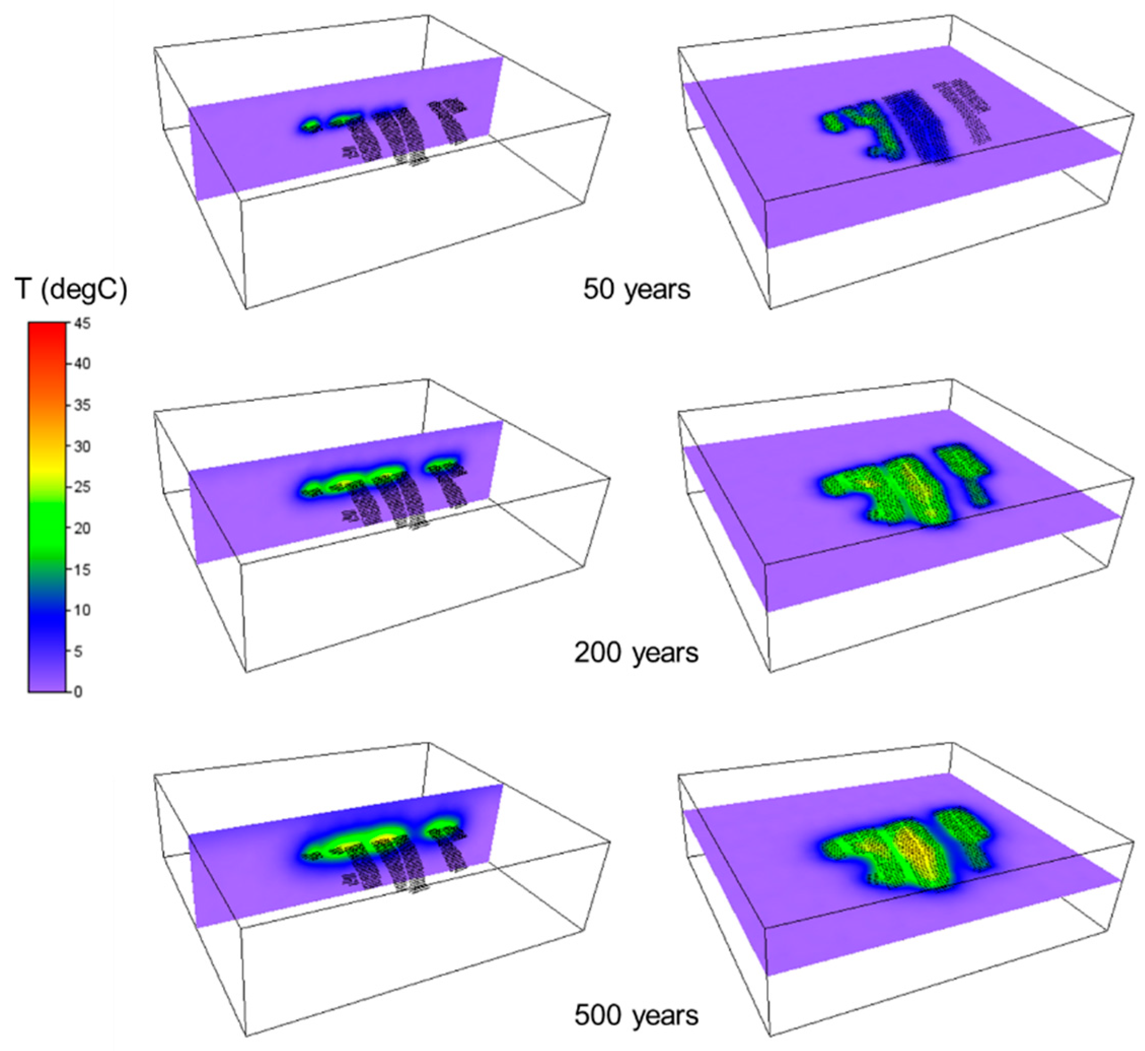
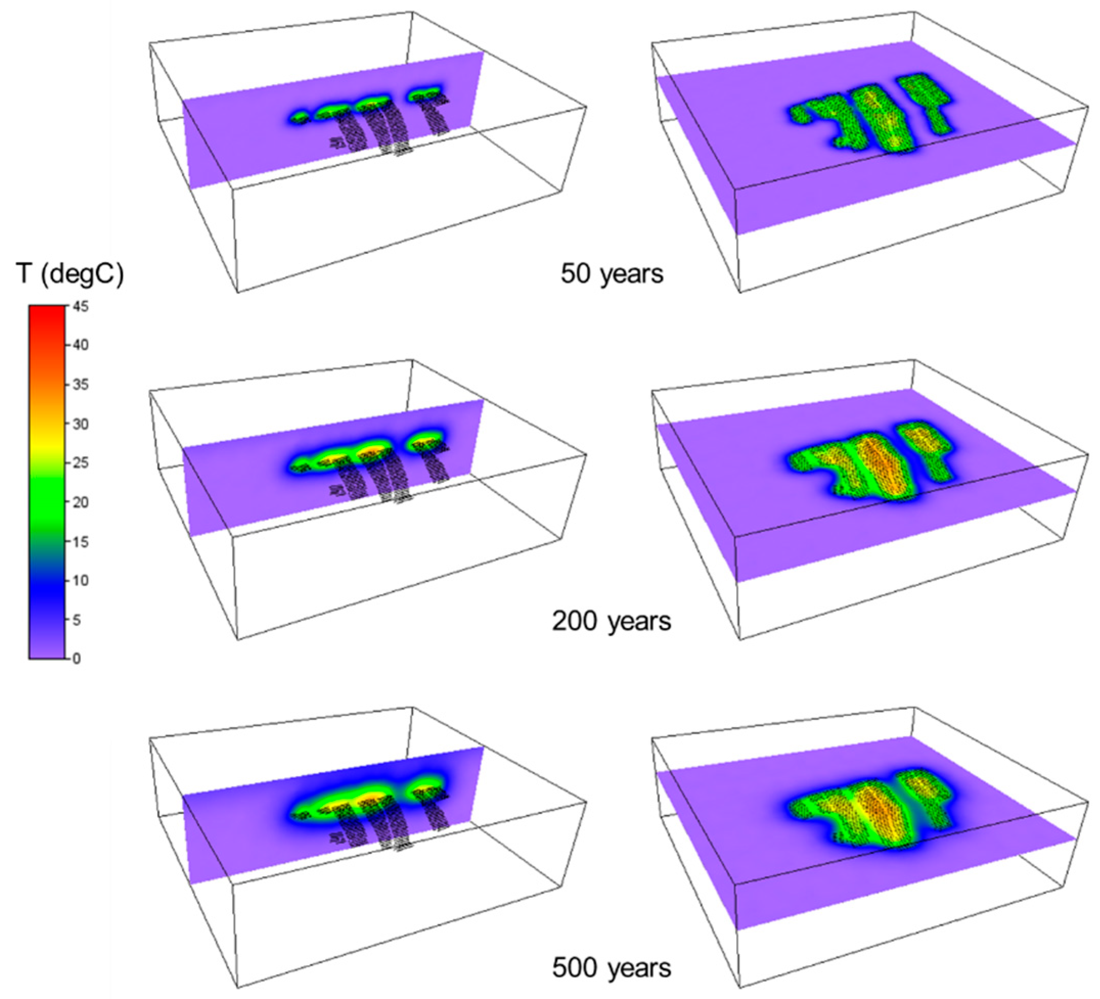
The spatial and temporal evolution of the rock temperature increase resulting from simultaneous panel heating is shown in
Figure 7. Temperature distributions are presented in both horizontal and vertical sections at selected times. At early stages, temperature increases are strongly localized around the deposition panels. With increasing time, heat diffuses outward into the surrounding rock mass, forming a repository-scale thermal halo, while temperatures within the panels gradually decrease due to radioactive decay and thermal equilibration.
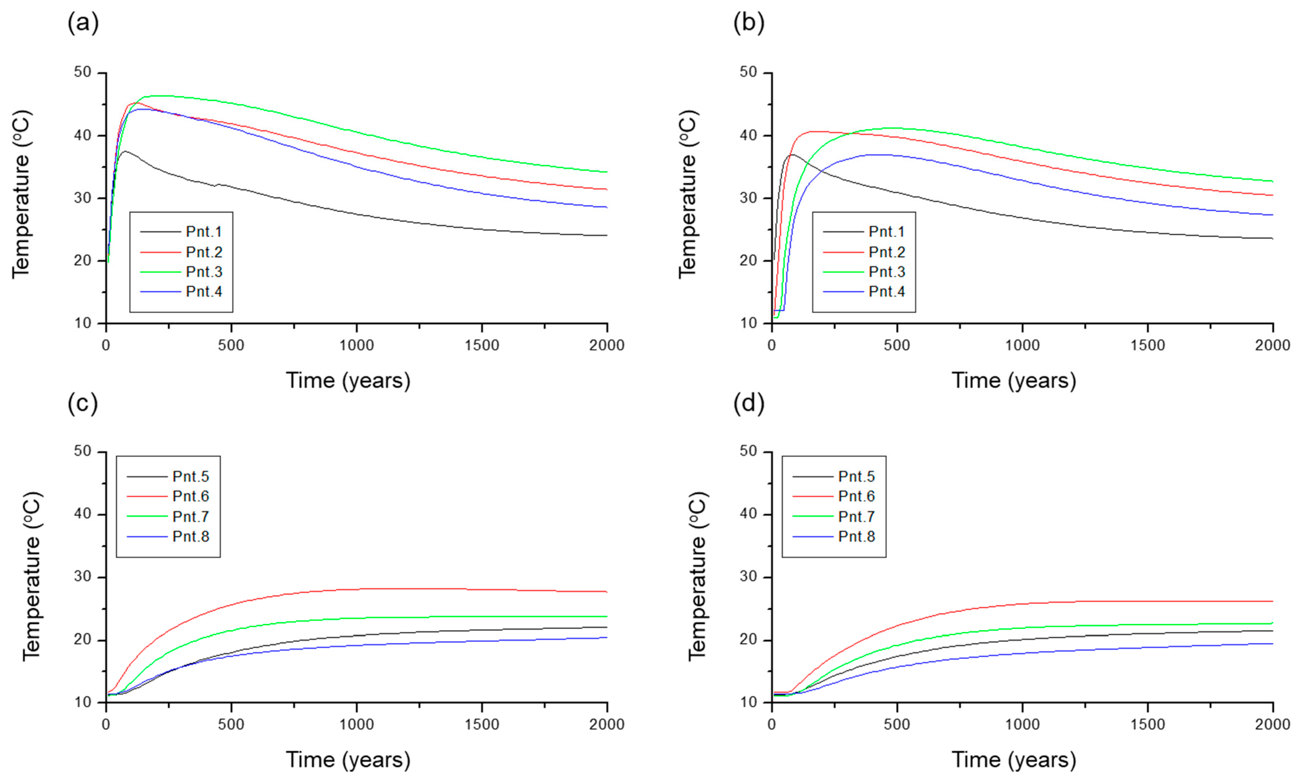
Figure 8 shows the rock temperature increase evolution associated with the sequential panel heating. While both scenarios exhibit similar qualitative heat-propagation patterns, the simultaneous heating case results in higher and more spatially extensive temperature increases at early times. Rock temperatures are monitored at the centres of the repository panels (points 1–4 in
Figure 5c). The resulting temperature histories for the all-panel simultaneous heating scenario are shown in
Figure 9a,c, while the corresponding results for the sequential panel heating scenario are presented in
Figure 9b,d.
5.2. Fracture Shear Displacements
An increase in rock temperature due to decay heat from spent nuclear fuel leads to thermal expansion of the rock mass, which in turn induces stress redistribution and shear displacement along embedded fractures. In this section, the evolution of thermally induced shear displacement of repository fractures is analyzed for the simultaneous and sequential panel heating scenarios.
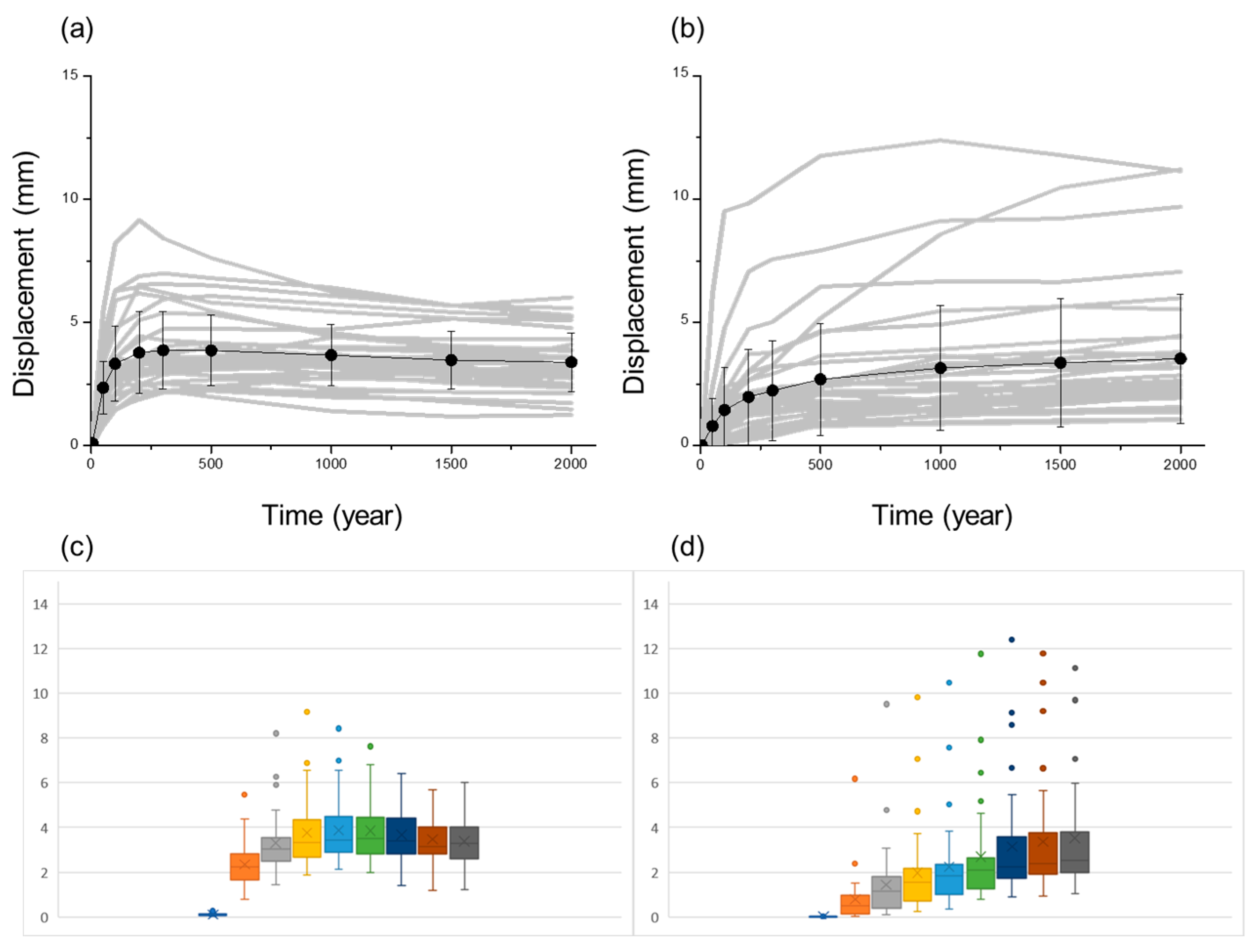
Figure 10 presents the evolution of thermally induced shear displacement for the simultaneous panel heating case.
Figure 10a shows fractures located within the repository panel footprints. The grey curves represent the shear displacement evolution of individual fractures (n = 33), and the black dots denote the mean displacement at selected times. The vertical error bars correspond to one standard deviation, illustrating the displacement variability around the mean. A rapid increase in displacement occurs shortly after the onset of heating, reflecting the strong thermal stress concentration in the near-field region. The displacement reaches a maximum during the early thermal phase and then gradually decreases as decay heat declines and thermally induced stresses relax. Although a residual displacement remains (see
Section 6. Discussion), the overall response is characterized by an early peak followed by stabilization. The relatively compact grouping of the grey curves indicates moderate variability among fractures within the footprint.
Figure 10b presents fractures located outside the repository panel footprints (n = 35). In this case, shear displacement increases more gradually and continues to accumulate over longer timescales. The delayed onset reflects the time required for heat to diffuse outward from the heated panels. The dispersion of the grey curves is more pronounced than in
Figure 10a, and the standard deviation bars are correspondingly larger. This indicates greater heterogeneity in the far-field response, where thermal stress redistribution interacts with the pre-existing structural and stress conditions.
Figure 10c,d provide the box–whisker representations of the same datasets for fractures within and outside the footprints, respectively. For fractures within the footprints, the interquartile ranges remain relatively compact, and the medians show stabilization after the early peak. In contrast, fractures outside the footprints exhibit wider interquartile ranges and longer whiskers, particularly at later times, confirming the larger variability and the presence of higher displacement values in the far field.
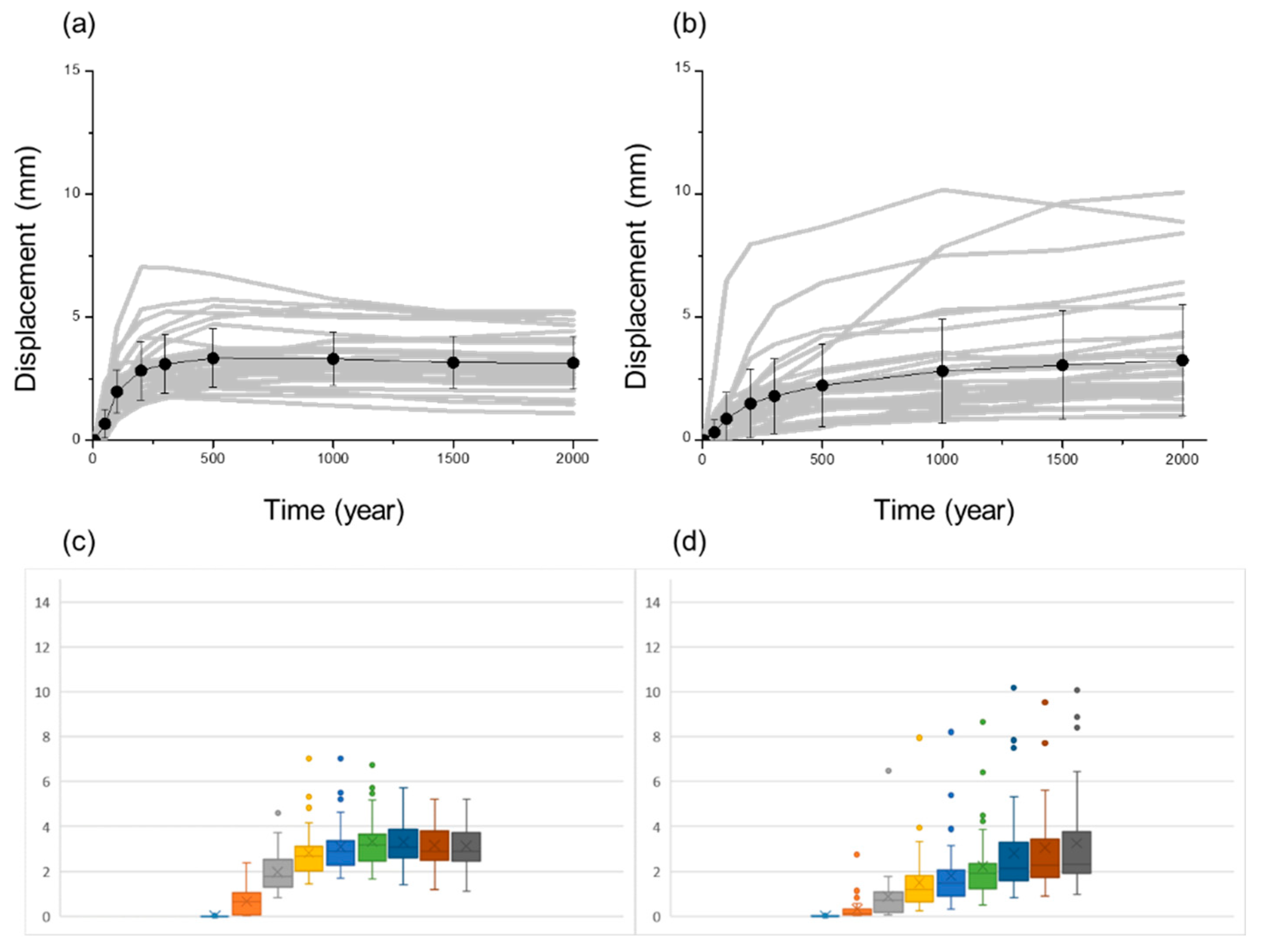
Figure 11 presents the evolution of thermally induced shear displacement for the sequential panel heating case. Same as in
Figure 10,
Figure 11a shows fractures located within the repository panel footprints. The grey curves represent the shear displacement histories of individual fractures, and the black dots indicate the mean values at selected times. The vertical error bars correspond to one standard deviation, illustrating the variability around the mean. As heating progresses panel by panel, shear displacement increases during the early thermal phase of each activated panel. Compared with the simultaneous heating case, the magnitude of the initial displacement peak is slightly reduced and the spread of individual fracture responses is somewhat narrower. After reaching a maximum, displacement stabilizes and gradually decreases as decay heat diminishes and thermal stresses relax. A residual displacement remains at later times, indicating permanent thermo-mechanical adjustment of the fracture network.
Figure 11b presents fractures located outside the repository panel footprints. The displacement increase is delayed relative to the within-footprint case, reflecting the time required for thermal diffusion from the sequentially activated panels. Shear displacement accumulates progressively over longer timescales. Although variability remains evident, the dispersion of individual curves and the size of the standard deviation bars are slightly smaller than in the simultaneous heating scenario. This suggests that staged heating moderates the magnitude and variability of far-field thermo-mechanical responses.
Figure 11c,d provide the box–whisker representations for fractures within and outside the footprints, respectively. For fractures within the footprints, the interquartile ranges are relatively compact and the medians show gradual stabilization after the early thermal phase. For fractures outside the footprints, the interquartile ranges are wider and the upper whiskers extend further, indicating greater heterogeneity in displacement magnitudes. However, both the median values and the overall spread are marginally lower than those observed under simultaneous heating.
A comparison between
Figure 10 and
Figure 11 highlights the influence of heating strategy on both the magnitude and variability of thermally induced fracture slip. Under simultaneous panel heating, all panels are activated at once, producing a relatively strong and spatially coherent thermal perturbation. In contrast, sequential heating distributes the thermal load over time, resulting in a more gradual stress evolution within the host rock. This difference is reflected in both the individual fracture displacement histories and their statistical distributions. For fractures located within the repository footprints, the overall temporal pattern remains similar in both cases, with a rapid increase in shear displacement during the early heating phase followed by stabilization and partial relaxation. However, the peak displacements in the simultaneous heating case are consistently slightly higher than those in the sequential case. The standard deviation bars and the spread of individual grey curves in
Figure 10 are also marginally larger. In
Figure 11, the staged activation leads to a more moderated near-field stress concentration, producing slightly lower mean values and reduced dispersion. This indicates that the intensity of the initial thermal shock directly influences the extent of shear mobilization in the near field. The difference becomes more pronounced for fractures outside the repository footprints. Under simultaneous heating, displacement increases more substantially and exhibits greater variability, as shown by the wider spread of curves and larger interquartile ranges in the box–whisker plots. In the sequential case, far-field fractures still display delayed and progressive displacement growth, but both the absolute magnitudes and the statistical spread are somewhat reduced. The smoother thermal loading history appears to dampen the cumulative stress redistribution that develops in the far field when all panels are activated simultaneously.
6. Discussion
The results indicate that the repository-scale thermo-mechanical response is governed not only by the magnitude of decay heat, but also by the temporal superposition of heat release from different panels. The simultaneous-heating case therefore serves as a conservative bounding scenario, whereas the sequential-heating case illustrates how staged emplacement moderates the rate of thermal build-up and the resulting stress redistribution. In this context, the delayed and relatively higher late-time temperatures observed in Panels B–D under sequential heating should be interpreted primarily as a consequence of their later activation time, rather than as evidence of cumulative thermal interference from previously activated panels. The sequential case is thus best regarded as a conceptual sensitivity analysis of staged repository closure rather than a prediction of a unique operational schedule.
The adopted panel-scale heat-loading formulation is appropriate for this purpose because it preserves the cumulative thermal effect associated with deposition-hole spacing and tunnel spacing at the scale of repository panels. At the same time, the formulation homogenizes the heat source and therefore smooths the strongest local temperature gradients that would occur in the immediate vicinity of individual canisters and deposition holes. The present simulations may therefore underestimate canister-scale peak thermal gradients and the associated local stress concentrations. The results should consequently be interpreted as representative of panel-scale thermo-mechanical response of the fractured rock mass, rather than as a fully resolved prediction of deposition-hole-scale maxima. Future higher-resolution analyses using explicit point-source or volume-source representations of individual canisters would be valuable for defining the applicability bounds of the present approximation.
Uncertainty also remains in the mechanical representation of fractures. The reduced smooth-joint stiffnesses obtained after calibration should not be interpreted simply as numerical weakening; rather, they represent an effective way to capture the compliance of natural fractures relative to the intact crystalline matrix and to avoid unrealistically stiff slip behaviour in the segmented smooth-joint representation. This calibration strategy is consistent with previous synthetic rock mass and PFC-based studies of fractured crystalline rock, including the calibration approach adopted by Yoon and Zang [
9]. Nevertheless, fracture stiffness and strength at Forsmark remain spatially variable, and additional sensitivity analyses on smooth-joint stiffness, cohesion, and friction would be valuable for constraining the range of thermally induced slip responses.
A related source of uncertainty is that the thermo-mechanical simulations were performed for one representative DFN realization selected from an ensemble of ten stochastic realizations. The selected realization reproduces the statistical distributions of fracture diameter and orientation of the full ensemble and is therefore suitable for mechanistic evaluation of the repository response. Even so, the present results should be interpreted as scenario-based rather than probabilistic. Additional simulations across multiple DFN realizations would be required to quantify the full spread of fracture-slip magnitudes and to assess the likelihood of more extreme responses associated with structural variability.
Within this framework, a fracture should be considered potentially critical only if its induced shear displacement approaches a magnitude capable of threatening canister integrity, commonly taken in the Swedish safety case as on the order of 50 mm. Fracture intersection with a deposition hole is therefore not, by itself, a sufficient criterion for criticality. The mechanical consequence depends also on fracture orientation, spatial position, and the geometry over which displacement could be transmitted to the canister. The predicted thermally induced displacements of 2–3 mm provide strong evidence that thermal loading alone is unlikely to generate canister-damaging shear, while also indicating that direct assessment of fracture–canister interaction would require higher-resolution modelling in which individual deposition holes and their local fracture geometries are explicitly represented.
Finally, the present model isolates thermo-mechanical slip on pre-existing fractures and does not include excavation damaged zone development, initiation and propagation of new cracks, or fully coupled hydro-mechanical feedbacks. These omissions are important when interpreting the long-term residual displacement. Residual shear on rough fractures may promote permanent dilation and associated transmissivity increase, but gouge generation, asperity damage, normal-stress redistribution, and bentonite swelling could partly offset such hydraulic enhancement. Likewise, EDZ fractures and newly generated cracks could either promote coalescence and localization on larger connected structures or distribute deformation over a larger number of smaller discontinuities. The residual-slip and aperture-based transmissivity estimates presented in this study should therefore be regarded as first-order indicators of possible long-term evolution rather than deterministic predictions of repository hydraulic performance.
7. Implications for Repository Operation and Safety
The comparison between the simultaneous and sequential panel heating scenarios shows that both the magnitude and spatial distribution of temperature increase in the host rock depend on the emplacement and closure sequence of deposition holes, tunnels, and panels. Sequential emplacement results in a slightly more gradual thermal build-up and slightly lower peak temperatures at given locations than the conservative case in which all-panel heating is activated simultaneously. This demonstrates that the thermal evolution of the repository is not a fixed outcome, but can be influenced through operational strategy. By adjusting the timing and order of panel construction, emplacement and closure, it could be possible to influence where and when peak temperatures occur within the repository rock mass. Because thermally induced stresses are directly governed by temperature changes and gradients, the same operational control extends to stress evolution. Optimizing the emplacement sequence therefore provides a practical means of moderating both temperature and stress perturbations at different locations. Such moderation may be beneficial not only for long-term post-closure conditions, but also during construction and operational phases, where limiting unfavourable stress concentrations in mechanically sensitive rock volumes can be advantageous.
With respect to fracture response, the simulations show that fractures located within the panel footprints experience a rapid increase in shear displacement during the early post-closure period. The displacement peaks at approximately 200 years and then gradually decreases as decay heat diminishes and thermally induced stresses relax. The average peak displacement is on the order of 2–3 mm. This magnitude is more than one order of magnitude smaller than the canister damage threshold of approximately 50 mm adopted by SKB, as discussed by Fälth et al. [
3]. Even under the conservative simultaneous heating scenario, the predicted thermally induced slip remains far below the displacement level considered critical for canister integrity. Comparable results have been obtained in previous thermo-mechanical analyses of repository-scale heating in crystalline rock. Numerical simulations of the inner section of the Äspö Prototype Repository using 3DEC have reported shear displacements of similar magnitude under thermal loading (Lönnqvist and Hökmark [
40]; Fälth [
41]). Together, these studies support the conclusion that thermally induced fracture slip remains limited to the millimetre scale and does not approach the 50 mm threshold associated with canister damage.
It is nevertheless important to emphasize that the present analysis does not directly translate simulated fracture slip into canister damage probability. Although the predicted displacements are far below the 50 mm threshold, the mechanical impact of a slipping fracture on a canister depends not only on the magnitude of slip, but also on the geometry and spatial relationship between the fracture and the deposition hole. Fracture orientation is particularly relevant. Steeply dipping or near-vertical fractures are less likely to intersect a vertical deposition hole over a significant contact length, whereas gently dipping fractures have a higher probability of intersecting the deposition hole and potentially transmitting displacement across it. A rigorous assessment of canister damage would therefore require explicit consideration of fracture orientation, spatial position, intersection geometry, and contact mechanics between the fracture plane and the canister. Such analysis lies beyond the scope of the present thermo-mechanical evaluation, which aims to bound the magnitude of thermally induced slip in the surrounding rock mass. The modelling was conducted at the scale of repository panels. Individual deposition tunnels and deposition holes were not represented explicitly. Instead, the repository was treated as a distributed heat-emitting rock volume, with heat input applied at panel scale. This simplification was necessary due to computational limitations that prevented a fully resolved geometrical representation of all deposition tunnels and holes. Higher-resolution modelling is left for future work aimed at refining the engineering control of repository-scale thermo-mechanical perturbations.
Although shear displacement within the panel footprints decreases after the early thermal peak, it does not return to zero. A residual shear displacement remains in the long term. Because natural fractures are rough and commonly exhibit dilatant behaviour during shear, permanent slip may be accompanied by a small but persistent increase in mechanical aperture. Fractures that were initially closed or hydraulically tight may therefore become slightly more open over time. From a long-term perspective, even modest aperture changes may influence the hydraulic characteristics of the fracture network. A simple first-order estimate relates aperture increase (
) to shear displacement (
) through a dilation angle (
), expressed as
. Millimetre-scale shear displacements of 2–3 mm combined with modest dilation angles of a few degrees produce sub-millimetre aperture increments. When translated into hydraulic behaviour using a cubic-law approximation, transmissivity scales with the cube of aperture. As a result, even relatively small aperture increases may lead to noticeable relative changes in transmissivity, particularly for fractures that initially have small hydraulic apertures. These calculations remain approximate and depend on assumptions regarding dilation angle and initial aperture, but they provide a physically transparent link between thermo-mechanical slip and potential hydraulic modification. This relationship is illustrated in
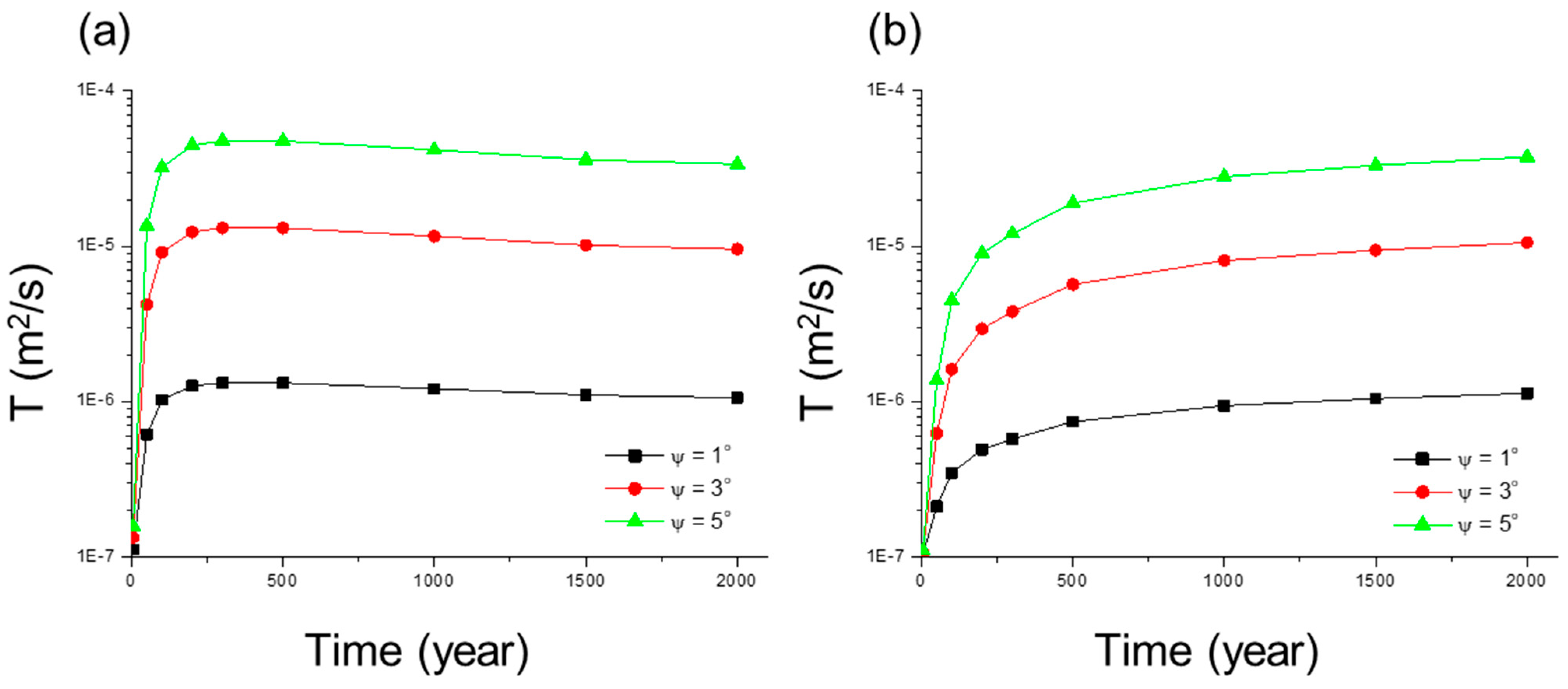
Figure 12, which presents estimated transmissivity changes derived from the simulated shear displacements under the simultaneous panel heating scenario. The estimates are shown for three assumed dilation angles (
) of 1°, 3°, and 5°.
Figure 12a shows fractures located within the panel footprints, and
Figure 12b shows fractures outside the footprints. For fractures within the footprints, transmissivity increases rapidly during the early thermal phase, reflecting the rapid rise in shear displacement. The magnitude of transmissivity change depends strongly on the assumed dilation angle, with larger angles producing substantially higher relative increases. After reaching a maximum, transmissivity decreases slightly but remains elevated compared with the initial condition, consistent with the residual component of slip. For fractures outside the footprints, transmissivity increases more gradually and continues to develop over longer timescales, mirroring the delayed and progressive shear displacement observed in the mechanical results. Although the transmissivity ratios are somewhat smaller than those for near-field fractures at equivalent dilation angles, the long-term trend indicates sustained enhancement before stabilization. In both cases, the curves highlight the strong sensitivity of transmissivity to small aperture variations.
It should be noted that, the hydraulic response of a shearing fracture is not governed by dilation alone. Shear slip may cause asperity damage, crushing, and the generation of gouge material. Fine debris produced during slip can accumulate within the fracture void space and partially clog flow paths, thereby reducing the effective hydraulic aperture. Normal stress redistribution during thermal loading may also promote partial closure in some regions. These processes may offset or locally counterbalance the transmissivity increase predicted from simplified dilation-based models. The transmissivity changes shown in
Figure 12 should therefore be interpreted as indicative trends rather than precise predictions of long-term flow evolution. Recent studies further emphasize that thermally induced slip and dilation are sensitive to heating rate, stress state, and fracture surface properties. Zhuang et al. [
42] demonstrated that heating rate can significantly influence fault reactivation behaviour, with implications for long-term repository safety. Sun et al. [
43] showed experimentally that fracture surface roughness and initial stress conditions strongly affect thermal stress development and mechanical response in fractured granite. These findings underline that dilation behaviour, and therefore transmissivity evolution, is inherently geometry- and stress-dependent. Investigation of hydraulic characteristics of thermally induced sheared fractures is currently being addressed within the SAFENET-2 task of the DECOVALEX project, which integrates laboratory and in situ experiments to examine fracture evolution from laboratory to field scale [
44]. Such work is expected to provide improved constraints on aperture evolution and flow changes under thermal loading.
An important limitation of the present study is that it does not consider fracture growth, new crack initiation, or interaction between pre-existing fractures. In particular, new cracks may be generated during the construction phase as part of the excavation damaged zone (EDZ) surrounding tunnels and deposition holes. These EDZ-related fractures may subsequently grow or reactivate during the thermal phase after closure, driven by thermo-mechanical stress redistribution. Under such conditions, cracks may propagate, new fractures may initiate at bridges between existing discontinuities, and previously separate fractures may coalesce into larger connected structures. If such coalescence occurs, larger effective fractures may develop with greater slip potential than smaller, isolated fractures, and the shear displacement magnitudes reported here could increase, together with their variability.
At the same time, the opposite effect may also be conceivable. The presence of EDZ fractures and newly created discontinuities increases the number of fractures available to accommodate deformation. Instead of concentrating shear displacement on a limited number of pre-existing fractures, part of the thermo-mechanically induced deformation may be distributed over multiple smaller fractures. In that case, individual fracture displacements could be reduced because slip is partitioned among several discontinuities. The net outcome therefore depends on the competition between fracture coalescence, which promotes localization and potentially larger slip on fewer structures, and fracture proliferation, which promotes distributed deformation and potentially smaller slip per fracture. Resolving this balance requires explicit modelling of fracture initiation, propagation, and interaction, which was beyond the scope of the present work.
The current simulations focus on slip along pre-existing fractures under prescribed thermal loading at panel scale. Fracture growth and EDZ–fracture interaction processes were intentionally excluded in order to isolate the thermo-mechanical response of the existing fracture network. Nevertheless, these processes represent a critical topic for future studies aimed at evaluating upper-bound fracture deformation and the long-term evolution of hydraulic connectivity in the repository system. Incorporating EDZ development, crack propagation, and fracture coalescence within a fully coupled thermo–mechanical framework would allow assessment of both localization and distribution effects on shear displacement and transmissivity.
8. Conclusions
In this study, a three-dimensional discrete element modelling framework was developed and applied to investigate the long-term thermo-mechanical evolution of the fractured crystalline host rock at the Forsmark site in Sweden. The work provides an independent analysis of repository-scale thermal loading and fracture response, complementing and critically examining the thermo-mechanical assessments presented in the Swedish safety case by SKB. The objective has been to establish a transparent, mechanistic basis for evaluating the magnitude and implications of thermally induced fracture slip under repository-relevant conditions.
The model explicitly represents the repository layout at panel scale, including deposition panels embedded within a rock mass that contains deterministic deformation zones and a stochastic discrete fracture network. Fracture slip is simulated explicitly through smooth-joint contacts, allowing shear displacement to develop in response to time-dependent thermal loading from spent nuclear fuel. Heat release from the canisters is implemented using a physically consistent decay power function and a panel-based heat-loading strategy that accounts for deposition-hole spacing and tunnel spacing. Although individual deposition holes and tunnels are not geometrically resolved due to computational limitations, the panel-scale representation captures the essential features of repository-scale thermal evolution.
Two end-member heating scenarios were analyzed. The first represents a conservative upper-bound case in which all panels begin releasing heat simultaneously. The second reflects staged emplacement and closure, with panels activated sequentially. The results show that repository-scale temperature evolution depends on the emplacement and closure sequence. Simultaneous heating produces higher and more abrupt temperature increases, while sequential heating results in a more gradual thermal build-up and slightly lower peak temperatures at given locations. These differences translate directly into differences in thermally induced stress redistribution. The findings demonstrate that temperature and stress perturbations in the host rock are not fixed outcomes but can be influenced through repository design and operational strategy.
Thermally induced fracture shear displacement exhibits a systematic temporal pattern. Fractures located within the panel footprints experience a rapid increase in shear displacement during the early post-closure phase, with peak values occurring at approximately 200 years after closure. The average peak shear displacement is on the order of 2–3 mm, followed by a gradual decrease as temperatures decline and thermal stresses relax. Fractures outside the panel footprints show smaller early-time displacements but continue to deform progressively over longer timescales as the thermal perturbation diffuses outward. In all cases, the simulated shear displacements remain more than one order of magnitude below the 50 mm canister damage threshold adopted by SKB, even under the conservative simultaneous heating scenario. Within the assumptions of the model, thermally induced fracture slip therefore remains well bounded relative to mechanical design limits.
While the predicted shear displacements do not indicate a direct mechanical threat to canister integrity, residual slip persists after the thermal peak. Given the dilatant behaviour of natural fractures, this residual deformation may be associated with small but permanent increases in mechanical aperture. First-order estimates based on dilation angles suggest that millimetre-scale slip can lead to sub-millimetre aperture increments. Because transmissivity scales with the cube of aperture, even modest dilation may produce noticeable relative changes in fracture flow capacity. The results indicate that thermo-mechanical evolution may therefore influence long-term hydraulic boundary conditions, particularly when considered together with stress redistribution and fracture interaction. At the same time, uncertainties remain regarding asperity damage, gouge production, and possible clogging effects, as well as the counteracting influence of bentonite swelling.
The implications for repository safety are therefore twofold. On the one hand, thermally induced fracture shear can be robustly bounded and shown to remain far below mechanical damage thresholds for the canister. On the other hand, the associated residual deformation and potential transmissivity changes may contribute to the long-term hydro-mechanical evolution of the rock mass. Thermo-mechanical processes are thus unlikely to represent a primary failure mechanism, but they may modify the conditions governing groundwater flow and related degradation processes over extended timescales.
Important limitations remain. The present study does not consider fracture growth, new crack initiation, or interaction with excavation damaged zone fractures. Such processes could either localize deformation through fracture coalescence or distribute deformation over a larger number of discontinuities, thereby altering both slip magnitudes and hydraulic connectivity. Incorporating fracture propagation, EDZ evolution, and fully coupled thermo–hydro–mechanical interactions within a discrete element framework will be essential for assessing upper-bound deformation scenarios and further strengthening the mechanistic basis of long-term safety assessment for spent nuclear fuel disposal in crystalline rock.