Article

In Vitro Micro-CT Assessment of a Novel Implant–Abutment Connection Under Static and Cyclic Loading


1
Department of Medicine, Surgery, and Pharmacy, University of Sassari, 07100 Sassari, Italy
2
Department of Dental Propaedeutics and Prophylaxis, Faculty of Dental Medicine, Medical University of Warsaw, 59 Nowogrodzka Street, 02-006 Warsaw, Poland
3
Independent Researcher, 07100 Sassari, Italy
4
Department of Prosthodontics, University of Ferrara, Via Luigi Borsari 46, 44121 Ferrara, Italy
5
Independent Researcher, Rhein83, 40128 Bologna, Italy
6
Faculty of Materials Science and Engineering, Warsaw University of Technology, Woloska 141, 02-507 Warsaw, Poland
7
Department of Biomedical and Dental Sciences and Morphofunctional Imaging, University of Messina, Via Consolare Valeria, 1, 98125 Messina, Italy
*
Author to whom correspondence should be addressed.
Appl. Sci. 2026, 16(5), 2394; https://doi.org/10.3390/app16052394
Submission received: 2 January 2026 / Revised: 20 February 2026 / Accepted: 26 February 2026 / Published: 28 February 2026

Abstract

The implant–abutment connection (IAC) is a critical determinant of the mechanical and biological performance of dental implants. Connection design and insertion torque may influence fatigue resistance, micromovement, and microgap formation, thereby affecting long-term implant success. This in vitro study evaluated a novel conical implant–abutment connection under controlled mechanical loading conditions. Methods: A sequential in vitro protocol was applied. Mechanical testing was conducted according to ISO 14801:2016 and included static and cyclic loading tests of the KS implant system inserted at two different torque values (35 Ncm and 70 Ncm). High-resolution micro-computed tomography (micro-CT) was performed after mechanical loading to evaluate implant–abutment interface integrity, microstructural alterations, and microgap behavior. Results: Static and cyclic loading tests revealed no observable differences between implants inserted at 35 Ncm and 70 Ncm, with all specimens completing the loading protocols without mechanical failure. Micro-CT analysis showed no evidence of microfractures, permanent deformation, or clinically relevant alterations at the implant–abutment interface. A stable and well-sealed connection was observed for both torque values following mechanical loading. Conclusions: Within the limitations of this in vitro study, the investigated conical implant–abutment connection demonstrated stable mechanical performance and preserved interface integrity after static and cyclic loading, regardless of whether implants were placed at 35 Ncm or 70 Ncm. These findings indicate that, under the present experimental conditions, both torque levels were associated with comparable structural integrity and mechanical stability of the investigated implant–abutment connection. This study should be interpreted as a preliminary experimental investigation, designed to provide descriptive and mechanistic insights rather than statistically powered comparative conclusions. Further long-term clinical trials are required to confirm these preliminary results.

1. Introduction

Dental implants represent a predictable and widely adopted solution for the rehabilitation of partially and fully edentulous patients, with long-term survival rates exceeding 90% [1,2]. Continuous advancements in implant design, surface technology, and surgical–prosthetic protocols have significantly improved functional and aesthetic outcomes. Nevertheless, biological and mechanical complications persist, with marginal bone loss and failures at the implant–abutment connection (IAC) playing a central role in long-term implant prognosis.
The IAC functions simultaneously as a mechanical junction and a biological interface. Its geometry directly influences stress distribution, micromovement, microbial sealing, and peri-implant tissue stability [3]. Micromovements and microgaps at the IAC may facilitate bacterial penetration [4], triggering inflammatory responses that can progress to peri-implant mucositis or peri-implantitis [5,6]. Even microgaps of only a few micrometers can act as bacterial reservoirs, depending on connection design, manufacturing precision, and functional loading conditions [7].
Different IAC geometries—including external and internal hexagonal, conical (Morse taper), and hybrid designs—exhibit distinct biomechanical behaviors. Conical connections are widely favored due to their improved mechanical stability and sealing capacity, which reduce micromotion and microleakage [8]. However, mechanical loading may still induce deformation at the interface, particularly under high static or cyclic forces, potentially exacerbating microgap formation and compromising the integrity of the connection over time [4]. Occlusal forces vary considerably by region, reaching up to 350 N in posterior areas and approximately 193 N in anterior regions [7], while non-axial loading and angled abutments may further increase stress concentration at the IAC.
High-resolution micro-computed tomography (micro-CT) has emerged as a valuable non-invasive tool for three-dimensional assessment of IAC morphology, microgap dimensions, and deformation patterns, particularly when combined with controlled mechanical testing protocols [9,10,11,12]. Although a completely hermetic seal at the IAC is unattainable, high manufacturing precision and increased contact area can mitigate bacterial infiltration and stress concentration, thereby enhancing mechanical durability and fatigue resistance under functional loading [13,14,15,16]. In this context, insertion torque has been identified as a critical factor influencing the mechanical engagement of the implant–abutment interface, potentially affecting contact mechanics, preload maintenance, and resistance to deformation during loading.
While numerical approaches such as finite element analysis have contributed substantially to understanding stress distribution and theoretical mechanical behavior at the IAC, experimental investigations remain essential to directly assess the structural integrity of implant–abutment assemblies under clinically relevant loading conditions. In particular, micro-CT analysis following static and cyclic loading provides direct insight into microstructural alterations, deformation patterns, and potential damage at the interface.
Therefore, the primary aim of this preliminary in vitro study was to experimentally evaluate the structural integrity and mechanical behavior of a novel implant–abutment connection under controlled static and cyclic loading conditions using high-resolution micro-CT analysis. Two insertion torque levels (35 Ncm and 70 Ncm) were applied as experimental parameters to assess the structural stability of the implant–abutment interface under different preload conditions. The null hypothesis was that the investigated implant–abutment connection would maintain structural integrity following mechanical loading, with no detectable microstructural damage at the interface on micro-CT analysis.

2. Materials and Methods

2.1. Study Design and Experimental Workflow

This investigation was designed as an in vitro experimental study aimed at evaluating the mechanical behavior of a novel implant–abutment connection (IAC) through a sequential experimental approach. In accordance with the primary aim, the study focused on the experimental assessment of the mechanical behavior of the implant–abutment interface under controlled loading conditions.
Mechanical resistance was experimentally evaluated through standardized static and cyclic loading tests (ISO 14801:2016, Geneva, Switzerland), under different insertion torques. The mechanical performance of the newly developed KS implant–abutment connection (Osstem Implant, Seoul, Republic of Korea) was evaluated after implant placement using two different insertion torque values (35 Ncm and 70 Ncm). Both static and cyclic loading protocols were applied to assess resistance to deformation and fatigue under simulated functional conditions.
Following mechanical testing, high-resolution micro-computed tomography (micro-CT) was employed to identify potential microstructural alterations, deformation patterns, or damage within the implant–abutment complex induced by static and cyclic mechanical loading.

2.2. Experimental Sites and Standards

The study was conducted through a multicenter collaboration. Static and cycling loading tests were carried out at Rehin 83 (Bologna, Italy) using an MTS Acumen testing system, while micro-CT analyses were performed at the Department of Dental Prosthetics, Faculty of Dental Medicine, University of Warsaw. Data analysis and interpretation were completed at the University of Sassari, Department of Medicine, Surgery and Pharmacy. All experimental procedures were conducted in strict accordance with ISO 14801:2016 for the dynamic fatigue testing of endosseous dental implants.
The null hypothesis (H0) was that no observable differences in structural integrity would be identified between insertion torque groups following mechanical loading.

2.3. Implant System and Design Characteristics

The KS dental implant system (Osstem Implant) features a 1.5° tapered macrodesign, specifically engineered to achieve high primary stability and to support immediate loading protocols. The implant body incorporates a double self-tapping thread with a Helix Cutting Edge, which facilitates controlled insertion and optimized engagement with the surrounding bone. The newly developed KS implant is further characterized by an increased implant wall thickness and a deeper 15° conical implant–abutment connection, both intended to improve mechanical resistance under functional loading. An additional sealing element located at the base of the connection is designed to improve interface stability and reduce micromovement and potential microleakage. All KS implants share a standardized 2.1 mm internal hexagon, independent of implant diameter, allowing for simplified surgical and prosthetic handling. The system is compatible with implant diameters ranging from 3.5 mm to 7.0 mm. A novel three-slot abutment retention mechanism, manufactured using ultra-precision machining technology, was incorporated to ensure accurate and stable implant–abutment positioning. This design allows for a controlled interference fit between implant and abutment, providing mechanical stability even prior to screw tightening. Such a configuration facilitates one-handed abutment handling during clinical procedures and minimizes the risk of loosening or accidental disconnection during both surgical and prosthetic phases.

2.4. Static and Cyclic Loading Under Different Insertion Torques

The in vitro mechanical test was designed to evaluate the influence of different insertion torque values on the mechanical behavior and stability of the KS implant–abutment connection under static and cyclic loading conditions. KS implants (Osstem Implant, Seoul, Republic of Korea) were inserted into epoxy resin blocks measuring 15 × 15 × 22 mm, selected to simulate bone tissue (Dentalstore & Edizioni Lucisano SRL, Milan, Italy). Implant placement was performed according to the manufacturer’s official surgical protocol and standardized across all specimens.

2.5. Randomization and Allocation

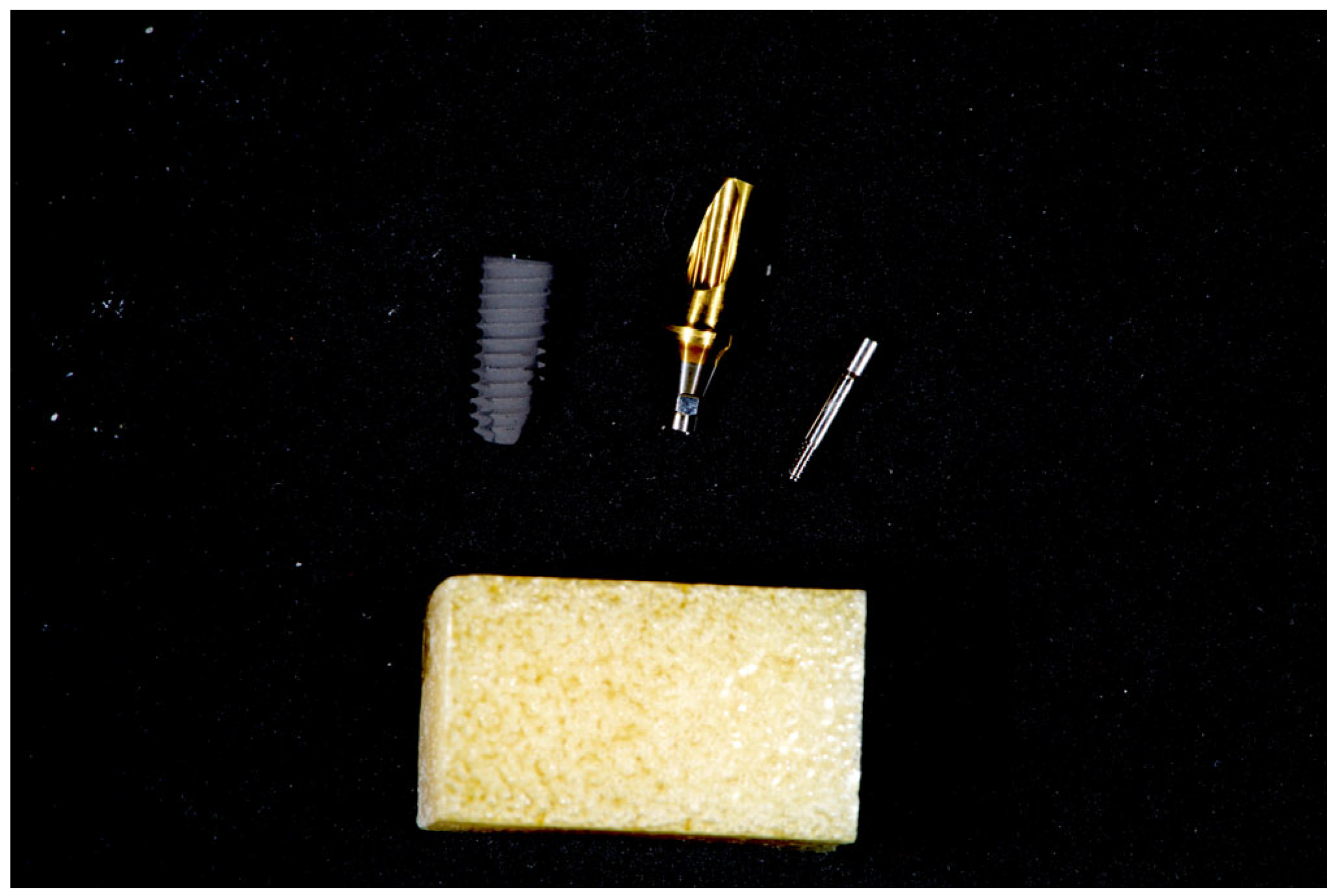
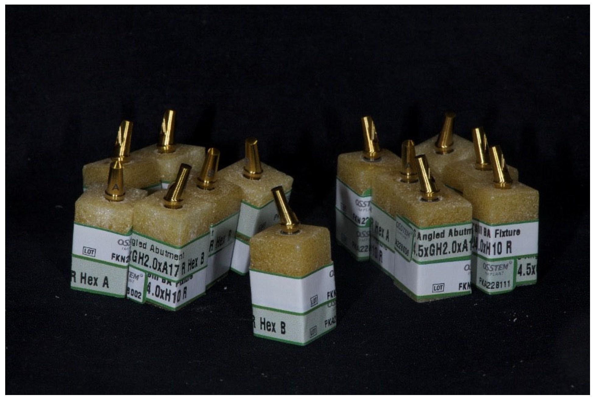
A total of 13 resin blocks were prepared and divided into three experimental groups. After specimen preparation, implants were allocated to the 35 Ncm (Group A) or 70 Ncm (Group B) groups using a computer-generated random sequence (simple randomization, 1:1 ratio). Allocation was concealed by assigning each specimen a unique alphanumeric code by an operator not involved in mechanical testing. The operator performing the MTS Acumen loading tests was blinded to group assignment (specimens were identified only by code and external marks were applied after allocation to allow tracking during handling). The assignment of individual specimens to the different loading sub-protocols (static and cyclic; and the single load-to-failure specimen per group) followed the pre-defined experimental plan described in Table 1 (Figure 1 and Figure 2):
  • - Group 1—Control (C): One specimen with a KS implant inserted at 35 Ncm, used exclusively for calibration of the MTS Acumen testing system and for baseline micro-CT assessment of the implant–abutment interface.
  • - Group 2—Group A (35 Ncm): Six specimens identified by one black reference mark and labeled A1–A6. Five specimens (A1–A5) were subjected to static and/or cyclic loading protocols. One specimen (A6) was subjected to static loading until fracture or until a maximum load of 1400 N was reached.
  • - Group 3—Group B (70 Ncm): Six specimens identified by two black reference marks and labeled B1–B6. Five specimens (B1–B5) were subjected to static and/or cyclic loading protocols. One specimen (B6) was subjected to static loading until fracture or until a maximum load of 1400 N was reached.

2.5.1. Micro-CT Baseline Assessment

Prior to mechanical testing, a baseline high-resolution micro-computed tomography (micro-CT) scan (Scan 0) was performed on the control specimen (Group C) to document the “expected normal” morphology of the implant–abutment interface in the unloaded condition.

2.5.2. Loading Protocols and Micro-CT Evaluation

Mechanical loading tests were conducted using an MTS Acumen testing system. Following each loading protocol, micro-CT scans (Scan 1) were performed to evaluate potential microstructural changes at the implant–abutment interface. The loading protocols were summarized in Table 1.

2.5.3. Outcome Measures and Statistics

Micro-computed tomography (µCT) imaging was performed using a MICRO XCT-400 system (Xradia, Zeiss, Pleasanton, CA, USA) operated at 140 kV and 70 μA. For each specimen, 1000 projection images were acquired with an exposure time of 4 s using a 4× objective lens. Scanning parameters yielded an isotropic voxel size of 5 μm, enabling high-resolution three-dimensional characterization of the implant–abutment interface and adjacent structures.
Volume reconstruction was completed using the manufacturer’s proprietary reconstruction software. The reconstructed datasets were subsequently exported to Avizo Fire (Thermo Fisher Scientific, Waltham, MA, USA) for advanced processing, visualization, and analysis. Three-dimensional rigid registration was applied to all volumes to ensure spatial alignment and identical orientation, thereby allowing reproducible cross-sectional and inter-specimen comparisons.
The primary outcome of the analysis was the structural integrity of the implant–abutment connection (IAC) after application of two different insertion torque levels (35 Ncm and 70 Ncm) and subsequent mechanical loading. Twelve implants were evaluated in total, comprising six specimens per torque group. The objective was to identify microstructural alterations potentially associated with mechanical stress, including deformation, interface disruption, or damage.
For each specimen, a standardized region of interest (ROI) corresponding to the IAC was defined, extending approximately 0.9 mm coronally and 4 mm apically along the conical connection. Multiplanar reconstructions (axial, sagittal, and coronal) and three-dimensional renderings were systematically inspected at high magnification.
Outcome assessment was conducted using a qualitative and descriptive approach. The evaluation focused on the presence and spatial distribution of:
  • − Cracks or fissures within the implant or abutment components.
  • − Discontinuities at the implant–abutment interface.
  • − Permanent deformation or distortion of the conical geometry.
  • − Localized defects or material irregularities.
  • − Visible microgaps along the interface.
Where visualization permitted, the microgap was examined circumferentially at three standardized reference levels (coronal, mid-connection, and apical) to ensure consistent intra- and inter-group comparisons. Observations were documented descriptively and supported by representative cross-sectional slices and three-dimensional renderings.
Categorical outcomes derived from qualitative micro-CT inspection (presence/absence of cracks, discontinuities, permanent deformation, localized defects, and microgaps) were summarized as frequencies and percentages for each group. Between-group comparisons were planned using Fisher’s exact test. When no events were observed in either group, inferential testing was not performed and results were reported descriptively.
Given the exploratory nature of the study and the limited sample size (n = 6 per group), no quantitative morphometric measurements or inferential statistical analyses were performed. Outcomes were therefore reported descriptively, emphasizing the comparative presence, pattern, and distribution of structural alterations between torque groups. Frequencies of observed findings were summarized narratively and tabulated where appropriate.
This methodological approach was adopted to provide a detailed structural characterization of the implant–abutment interface and to generate preliminary evidence regarding the influence of insertion torque and mechanical loading on connection stability.

3. Results

3.1. Results of Static and Cyclic Loading Tests

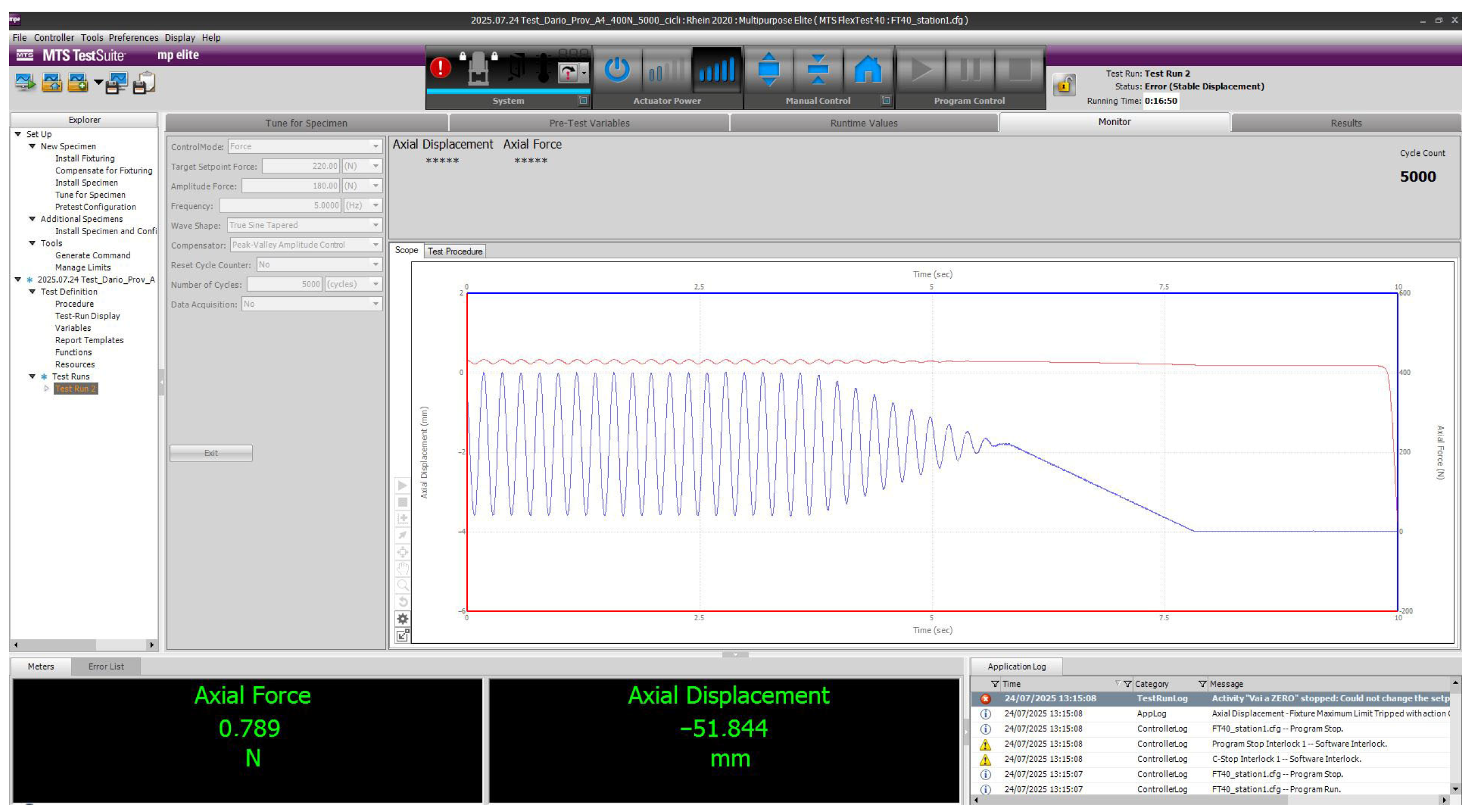
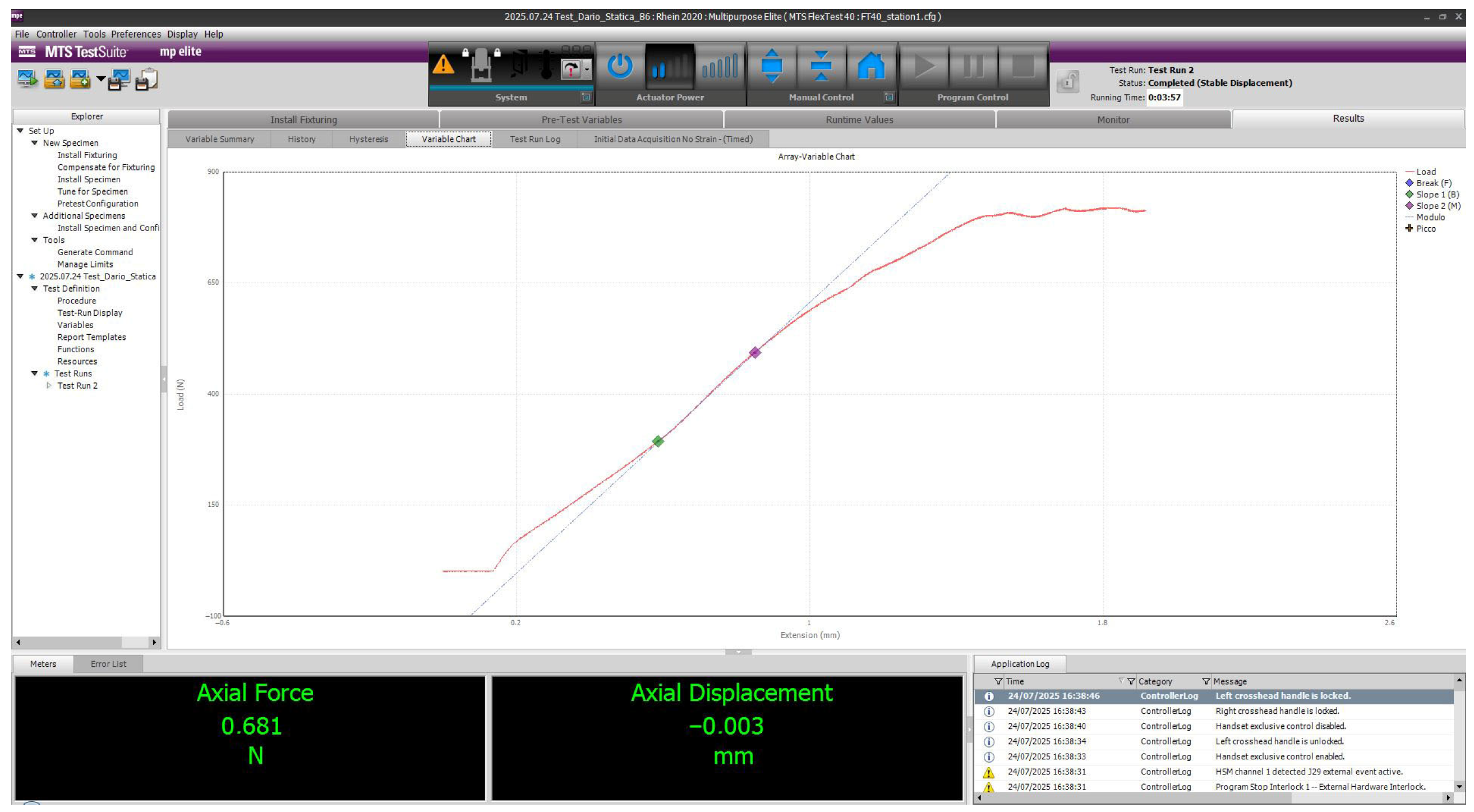
Static and cyclic loading tests performed on specimens A1–A5 (35 Ncm insertion torque) and B1–B5 (70 Ncm insertion torque) were successfully completed without mechanical failure (Figure 3). All samples withstood the prescribed loading protocols and completed the assigned number of cycles using the MTS Acumen system. No visible differences were observed between the samples within each series. A different mechanical behavior was observed during the static loading-to-failure tests performed on specimens A6 and B6 (Figure 4). In specimen A6 (35 Ncm insertion torque), the implant–abutment connection showed no signs of mechanical failure up to a load of 1200 N, which represented the maximum load achievable by the testing device before automatic shutdown due to overheating. In contrast, specimen B6 (70 Ncm insertion torque) exhibited initial signs of implant–abutment connection failure at approximately 800 N.

3.2. Micro-CT Evaluation of the Implant–Abutment Interface

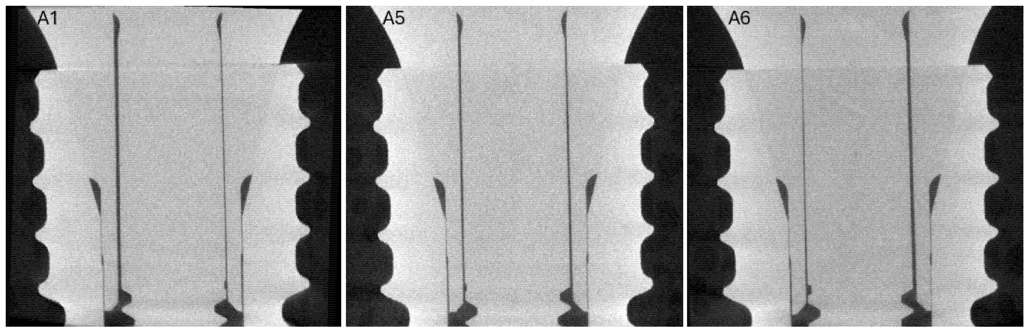
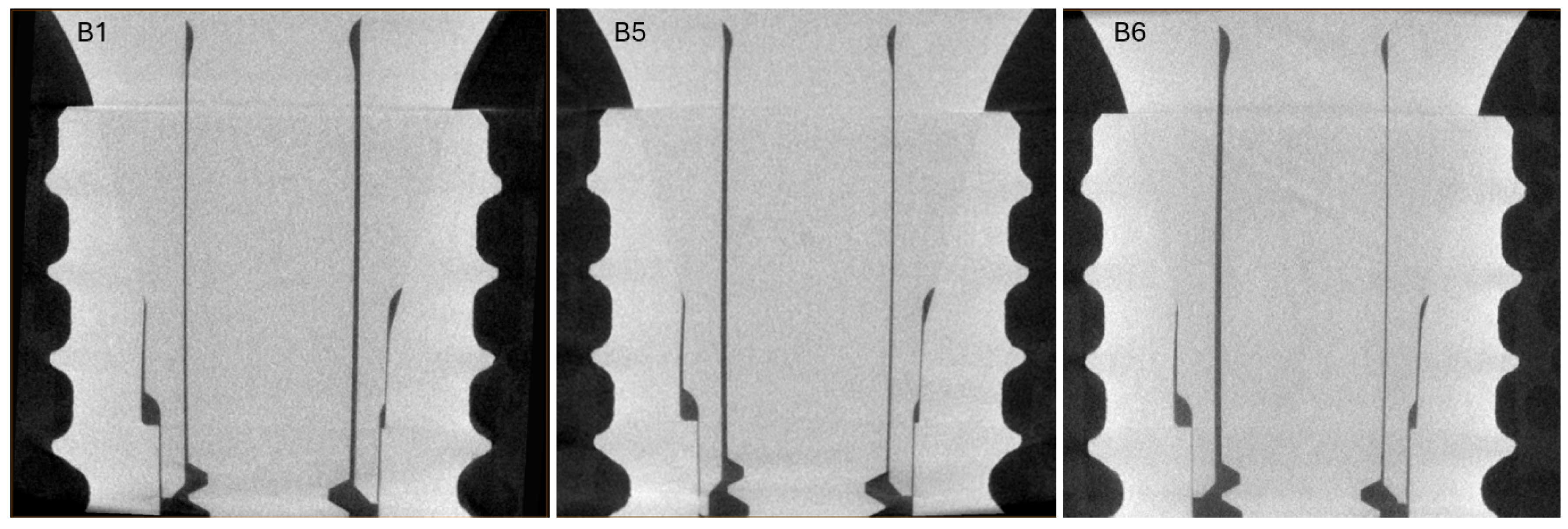
In general, no visible differences were observed between the samples within each series. Figure 5 and Figure 6 present representative cross-sections of the analyzed region for one of the series. High-resolution micro-computed tomography (micro-CT) analysis of three KS implant–abutment assemblies from Group B (70 Ncm insertion torque) revealed no evidence of microfractures, cracks, or permanent structural deformation following mechanical loading (Figure 5).
Three-dimensional superimposition of micro-CT datasets from Group A (35 Ncm) and Group B (70 Ncm) demonstrated comparable structural integrity of the implant–abutment interface in both groups. While specimens in Group B exhibited a greater degree of elastic deformation under equivalent static loading conditions, no signs of plastic deformation or irreversible damage were observed in any of the analyzed samples (Figure 6).
Finally, no cracks, fissures, discontinuities, permanent deformation, localized defects, or detectable microgaps were identified in any specimen in either group (0/6 vs. 0/6). Due to the absence of events, statistical comparison using Fisher’s exact test was not applicable, and outcomes were reported descriptively.

4. Discussion

This multicenter in vitro study was designed to evaluate the mechanical behavior of a novel implant–abutment connection using an experimental workflow based on torque-dependent static and cyclic loading combined with high-resolution micro-computed tomography (micro-CT). The null hypothesis, stating that no differences would be observed between implant–abutment assemblies tightened at 35 Ncm and 70 Ncm, was partially rejected. The mechanical performance of the KS implant–abutment connection was assessed under standardized static and cyclic loading conditions after implant placement with two different insertion torque values. Within the limits of the present in vitro investigation, no visible differences were observed between specimens tightened at 35 Ncm and 70 Ncm in terms of resistance to deformation or fatigue under cyclic loading. However, static loading suggests that the lower torque (35 Ncm) tolerated higher loads than the higher torque (70 Ncm). These findings suggest that both torque values are sufficient to ensure the mechanical stability of the investigated conical connection under simulated functional conditions. However, the torque may influence mechanical behavior. These observations indicate that the investigated implant–abutment connection maintained structural integrity across the tested torque range under the present experimental conditions. However, due to the exploratory nature of this study, no definitive conclusions regarding the mechanical or clinical implications of different insertion torque levels can be drawn [17].
During static loading-to-failure testing, specimens tightened at 35 Ncm tolerated higher loads before test interruption compared with those tightened at 70 Ncm. Although this observation might suggest a torque-dependent mechanical response, micro-CT analysis did not reveal corresponding structural damage, permanent deformation, or microfractures at the implant–abutment interface in either group. No abutment sinkdown or vertical displacement was observed after torque application or during functional loading, indicating stable seating of the conical connection throughout the observation period. Moreover, no visible, significant differences were detected between torque groups. Consequently, this isolated finding should be interpreted with caution and cannot be considered indicative of a systematic mechanical advantage associated with one insertion torque over the other.
Micro-CT analysis represented a key methodological strength of the present study, enabling non-destructive, three-dimensional evaluation of the implant–abutment interface following mechanical loading. Across all tested specimens, micro-CT imaging revealed no evidence of cracks, microfractures, or permanent deformation after static and cyclic loading. These results are consistent with previous investigations demonstrating that conical implant–abutment connections can maintain structural integrity even under elevated mechanical stress [6,11,12]. The absence of detectable damage also suggests that part of the applied load may have been absorbed by the resin blocks simulating bone tissue, which constitutes an inherent limitation of in vitro models.
Beyond the assessment of gross structural integrity, micro-CT evaluation provided valuable insight into the implant–abutment microgap, a parameter of both mechanical and biological relevance. Microgap formation at the implant–abutment interface is influenced by connection geometry, manufacturing tolerances, material properties, and surface finishing [7,9,11]. Enlargement of this microgap has been associated with bacterial leakage, loss of preload, screw-related complications, and inflammatory reactions in peri-implant tissues [8,9,10]. In the present study, the KS implant–abutment connection consistently demonstrated a stable and well-sealed interface, even after static and cyclic loading. This finding aligns with previous reports indicating that conical and locking-taper connections may reduce micromovement and bacterial penetration at the implant–abutment junction compared with earlier internal connection designs [7,16].
From a biological perspective, bacterial colonization of the implant–abutment interface has been implicated in the development of peri-implant inflammation and marginal bone loss [8,9]. Persistent microbial leakage can stimulate cytokine release and osteoclast activation, ultimately contributing to peri-implantitis [5]. Although the present investigation did not include biological or microbiological assays, the maintenance of a stable interface and the absence of detectable microgap enlargement observed on micro-CT suggest a potential protective effect against microbial contamination, which may be clinically relevant for long-term implant success.
Several limitations of this study must be acknowledged. The in vitro design, the use of resin blocks to simulate bone, and the relatively short-term loading protocols limit direct extrapolation of the findings to clinical conditions. In addition, the sample size was constrained by the complexity of the experimental protocol. Nonetheless, the integration of controlled mechanical testing and high-resolution three-dimensional imaging across multiple academic and industrial centers represents a methodological strength, providing robust experimental evidence for the mechanical reliability and interface stability of the investigated implant–abutment connection. The KS implant system is relatively recent, and long-term clinical data are still limited. However, emerging clinical evidence has suggested encouraging results, even in reduced-diameter configurations [1,2]. When considered together with the stable mechanical behavior and interface integrity observed in the present study, these findings support the potential clinical applicability of the KS implant–abutment connection, particularly in posterior regions, in patients with high occlusal loads, or in situations where mechanical reliability is critical. Within the limitations of this in vitro and qualitative micro-CT analysis, both insertion torque levels were not associated with detectable structural damage at the implant–abutment interface. Although these findings suggest that the tested conical connection can mechanically tolerate the applied torques without visible microstructural alterations, the absence of in vivo and long-term fatigue data prevents definitive conclusions regarding the biological or functional safety of higher tightening values. From a clinical perspective, the present findings provide preliminary experimental insight into the mechanical behavior of the investigated implant–abutment connection under controlled loading conditions. The absence of detectable structural damage or interface disruption on micro-CT analysis suggests that the conical connection design maintained structural integrity across the tested torque range. However, due to the in vitro design, limited sample size, and qualitative nature of the analysis, these observations should be interpreted with caution. Further quantitative, long-term, and in vivo investigations are required to determine the clinical implications of insertion torque and its potential influence on preload maintenance, biological sealing, and peri-implant tissue response. Therefore, clinical implications regarding insertion torque should be interpreted cautiously, and further quantitative, long-term, and in vivo investigations are required to establish evidence-based recommendations. Further long-term clinical and in vivo studies are warranted to confirm these preliminary observations and to clarify the biological implications of the mechanical performance demonstrated in vitro.

5. Conclusions

Within the limitations of this in vitro study, the investigated conical implant–abutment connection demonstrated stable mechanical behavior and preserved structural integrity following static and cyclic loading. These findings indicate that, under the present experimental conditions, both torque levels were associated with comparable structural integrity and mechanical stability of the investigated implant–abutment connection. Differences between torque conditions were observed only during static loading-to-failure testing, without evidence of visible microstructural damage or loss of implant–abutment interface integrity on micro-CT analysis. However, due to the exploratory nature of this study and its limited sample size, these observations should be interpreted cautiously and cannot be considered conclusive. Further quantitative, long-term clinical, and in vivo investigations are required to confirm these preliminary findings and to clarify the mechanical and biological implications of insertion torque in implant–abutment connections.

Author Contributions

Investigation, M.T., D.M., L.Z., C.C., S.M.M., A.I.L., S.C., R.B., R.M., J.J. and G.C.; data curation, M.T., G.C., D.M. and R.B.; supervision, M.T. and L.Z.; writing original draft, D.M. and M.T.; writing review editing, M.T. All authors have read and agreed to the published version of the manuscript.

Funding

This research originated from a Doctoral Thesis. The OSSTEM supplied all the materials.

Data Availability Statement

The original contributions presented in this study are included in the article. Further inquiries can be directed to the corresponding author.

Acknowledgments

The authors would like to thank Rhein83, in the persons of Gianni Storni and Raffaele Lombardo, for making their research facilities available for the execution of the static and dynamic mechanical tests. The authors also wish to thank Osstem Implant for performing the finite element analysis (FEA) and for carrying out and sharing the results of the initial static loading tests. Finally, the authors acknowledge Osstem Implant Headquarters for kindly providing the materials used in this study.

Conflicts of Interest

The authors declare no conflicts of interest. The Ethical Committee was not required for this study due to an vitro study.

References

  1. Krebs, M.; Schmenger, K.; Neumann, K.; Weigl, P.; Moser, W.; Nentwig, G.H. Long-term evaluation of ANKYLOS® dental implants, part i: 20-year life table analysis of a longitudinal study of more than 12,500 implants. Clin. Implant Dent. Relat. Res. 2015, 17, e275–e286. [Google Scholar] [CrossRef] [Scilit] [PubMed]
  2. Schropp, L.; Wenzel, A. Timing of single implant placement and long-term observation of marginal bone levels. Eur. J. Oral Implantol. 2016, 9, S107–S122. [Google Scholar] [PubMed]
  3. Kim, J.J.; Lee, J.H.; Kim, J.C.; Lee, J.B.; Yeo, I.L. Biological responses to the transitional area of dental implants: Material- and structure-dependent responses of peri-implant tissue to abutments. Materials 2019, 13, 72. [Google Scholar] [CrossRef] [Scilit] [PubMed]
  4. Kubasiewicz-Ross, P.; Fleischer, M.; Pitułaj, A.; Hadzik, J.; Nawrot-Hadzik, I.; Bortkiewicz, O.; Dominiak, M.; Jurczyszyn, K. Evaluation of the three methods of bacterial decontamination on implants with three different surfaces. Adv. Clin. Exp. Med. 2020, 29, 177–182. [Google Scholar] [CrossRef] [Scilit] [PubMed]
  5. Chaushu, L.; Shabat, R.; Gadyukov, A.; Chaushu, G. A two-piece dental implant comprising a replaceable thin titanium sleeve may be a new approach to re-osseointegration following peri-implant disease. Med. Hypotheses 2018, 121, 103–105. [Google Scholar] [CrossRef] [Scilit] [PubMed]
  6. Blum, K.; Wiest, W.; Fella, C.; Balles, A.; Dittmann, J.; Rack, A.; Maier, D.; Thomann, R.; Spies, B.C.; Kohal, R.J.; et al. Fatigue induced changes in conical implant-abutment connections. Dent. Mater. 2015, 31, 1415–1426. [Google Scholar] [CrossRef] [Scilit] [PubMed]
  7. Lopes de Chaves EMello Dias, E.C.; Sperandio, M.; Napimoga, M.H. Association Between Implant-Abutment Microgap and Implant Circularity to Bacterial Leakage: An In Vitro Study Using Tapered Connection Implants. Int. J. Oral Maxillofac. Implant. 2018, 33, 505–511. [Google Scholar] [CrossRef] [Scilit] [PubMed]
  8. Broggini, N.; McManus, L.M.; Hermann, J.S.; Medina, R.U.; Oates, T.W.; Schenk, R.K.; Buser, D.; Mellonig, J.T.; Cochran, D.L. Persistent acute inflammation at the implant-abutment interface. J. Dent. Res. 2003, 82, 232–237. [Google Scholar] [CrossRef] [Scilit] [PubMed]
  9. Jansen, V.K.; Conrads, G.; Richter, E.J. Microbial leakage and marginal fit of the implant-abutment interface. Int. J. Oral Maxillofac. Implant. 1997, 12, 527–540, Erratum in Int. J. Oral Maxillofac. Implant. 1997, 12, 709. [Google Scholar] [PubMed]
  10. Guindy, J.S.; Besimo, C.E.; Besimo, R.; Schiel, H.; Meyer, J. Bacterial leakage into and from prefabricated screw-retained implant-borne crowns in vitro. J. Oral Rehabil. 1998, 25, 403–408. [Google Scholar] [CrossRef] [Scilit] [PubMed]
  11. Meleo, D.; Baggi, L.; Di Girolamo, M.; Di Carlo, F.; Pecci, R.; Bedini, R. Fixture-abutment connection surface and micro-gap measurements by 3D micro-tomographic technique analysis. Ann. Ist. Super. Sanita 2012, 48, 53–58. [Google Scholar] [PubMed]
  12. Kapishnikov, S.; Gadyukov, A.; Chaushu, G.; Chaushu, L. Micro-CT Analysis of Microgap at a Novel Two-Piece Dental Implant Comprising a Replaceable Sleeve In Vitro. Int. J. Oral Maxillofac. Implant. 2021, 36, 451–459. [Google Scholar] [CrossRef] [Scilit] [PubMed]
  13. Cortesi Ardizzone, V. La connessione implantare: Meccanismi e implicazioni cliniche. Dent. Cadmos 2015, 90, 415–456. [Google Scholar]
  14. Tribst, J.P.M.; Özkara, N.; Blom, E.J.; Kleverlaan, C.J.; Ausiello, P.; Bruhnke, M.; Feilzer, A.J.; Dal Piva, A.M.d.O. The Effect of Implant–Abutment Contact Area on the Stress Generation of Bone-Level and Tissue-Level Implants. Appl. Sci. 2025, 15, 2744. [Google Scholar] [CrossRef] [Scilit]
  15. Chan, H.L.; Oh, W.S.; Ong, H.S.; Fu, J.H.; Wang, H.L. Impact of implantoplasty on strength of the implant-abutment complex. Int. J. Oral Maxillofac. Implant. 2013, 28, 1530–1535. [Google Scholar] [CrossRef] [Scilit] [PubMed]
  16. Dibart, S.; Warbington, M.; Su, M.F.; Skobe, Z. In vitro evaluation of the implant-abutment bacterial seal: The locking taper system. Int. J. Oral Maxillofac. Implant. 2005, 20, 732–737. [Google Scholar]
  17. Manfredini, M.; Ghizzoni, M.; Cusaro, B.; Beretta, M.; Maiorana, C.; Souza, F.Á.; Poli, P.P. High Insertion Torque-Clinical Implications and Drawbacks: A Scoping Review. Medicina 2025, 61, 1187. [Google Scholar] [CrossRef] [Scilit] [PubMed] [PubMed Central]
Figure 1. Implant and abutment connection with resin block.
Applsci 16 02394 g001
Figure 2. All 13 blocks ready for the static and dynamic loading.
Applsci 16 02394 g002
Figure 3. Representative example of the cyclic loading test, illustrating the load frequency applied during dynamic fatigue evaluation.
Applsci 16 02394 g003
Figure 4. This is the static test of the sample (B6) that shows the displacement of the machine that represents the deformation of the implant at around 800 N.
Applsci 16 02394 g004
Figure 5. Example tomographic visualizations: longitudinal projections of the region of interest within the implant for three samples from series A. No defects or damage to the implant material were observed.
Applsci 16 02394 g005
Figure 6. Example tomographic visualizations: longitudinal projections of the region of interest within the implant for three samples from series B. No defects or damage to the implant material were observed.
Applsci 16 02394 g006
Table 1. Summary of the static and cycling tests performed.
ProtocolSamplesStatic LoadingCyclic LoadingCyclesFrequency (Hz)Max Load (N)Micro-CT Evaluation
Static and Low-Cycle LoadingA1, B1400 N–120 s0–200 N1K5400Post-loading
Static Loading—Intermediate Cyclic LoadingA2, B2400 N–120 s0–400 N1K5400Post-loading
Progressive Cyclic LoadingA3, B3None0–400 N3K5400Post-loading
Progressive Cyclic LoadingA4, B4None0–400 N5K5400Post-loading
Extended Cyclic LoadingA5, B5None0–400 N10K5400Post-loading
Static Loading to FailureA6, B6Until fracture (or 1400 N)None--1400Post-loading
Disclaimer/Publisher’s Note: The statements, opinions and data contained in all publications are solely those of the individual author(s) and contributor(s) and not of MDPI and/or the editor(s). MDPI and/or the editor(s) disclaim responsibility for any injury to people or property resulting from any ideas, methods, instructions or products referred to in the content.