


Abstract
This paper investigates the prediction of the depth of penetration (DOP) for concrete targets under high-speed projectile impact using multiple simulation algorithms in LS-DYNA. Three numerical methods, i.e., the traditional finite element method (FEM), a fixed-coupling FEM-SPH (Smooth Particle Hydrodynamics) model, and an adaptive coupling FEM-SPH model, are employed to simulate the penetration processes. The computational results are compared against established empirical formulas to evaluate their predictive accuracy and efficiency. The findings indicate a distinct trade-off between numerical precision and computational cost. The adaptive FEM-SPH algorithm achieves the highest accuracy, with a maximum error of less than 10% across considered velocity ranges, and effectively captures cavity expansion effects. The standard FEM algorithm offers the highest computational efficiency, requiring less than half the time of the other methods, albeit with a maximum error of up to 25%. The fixed-coupling FEM-SPH model provides an intermediate solution, showing improved accuracy at velocities above 400 m/s but lower efficiency. This comparative analysis offers a practical guideline for selecting appropriate simulation techniques in protective structure design, balancing the demands for rapid estimation, detailed physical insight, and final safety verification.
1. Introduction
The study of projectile penetration into concrete targets under high-speed impact is a critical area of research with significant implications for the design of protective structures in both civil and military engineering [1,2,3]. Understanding the complex interaction between a high-velocity projectile and concrete is essential for enhancing the resilience of critical infrastructure, developing effective armor systems, and ensuring the safety of personnel and assets [4,5]. Reinforced concrete, widely used in various protective applications, exhibits highly nonlinear and dynamic responses when subjected to high-speed impact, characterized by phenomena such as material fragmentation, cratering, spalling, and complex stress wave propagation [6,7]. Accurately predicting the depth of penetration and understanding the associated penetration mechanisms are paramount for optimizing structural designs against such extreme loading conditions.
Traditional analytical and empirical models for predicting DOP often rely on simplified assumptions and may not fully capture the intricate material behavior and failure modes observed during high-speed penetration [8,9,10]. Experimental investigations, while providing invaluable data, are typically expensive, time-consuming, and limited in scope [11]. Consequently, numerical simulation methods have emerged as powerful tools for investigating these complex phenomena, offering detailed insights into the dynamic response of materials and structures under impact [12,13,14]. The LS-DYNA software, a widely recognized explicit finite element analysis code, is extensively utilized for simulating high-strain-rate events, including ballistic penetration, due to its robust material models and contact algorithms [15,16,17].
Among the various numerical techniques, the finite element method (FEM) is a well-established approach for modeling structural responses. However, for extreme deformation and material fragmentation scenarios, such as those encountered in high-speed penetration, traditional FEM can face challenges with mesh distortion and element deletion, which may compromise solution accuracy and stability [18,19]. To overcome these limitations, meshless methods like smooth particle hydrodynamics (SPH) have gained prominence, particularly for simulating large deformations and material failure [20,21]. The coupling of FEM and SPH, either through fixed coupling or adaptive coupling algorithms, offers a promising avenue to leverage the strengths of both methods: FEM for structural parts with moderate deformation and SPH for regions experiencing severe deformation and material damage [22,23]. While previous studies have explored these coupling techniques for various impact problems, a comprehensive comparative analysis focusing on their predictive accuracy and computational efficiency for high-speed penetration into concrete, particularly with an emphasis on adaptive FEM-SPH algorithms for DOP prediction, remains an area warranting further detailed investigation.
This paper aims to bridge this gap by systematically evaluating the performance of different simulation models within LS-DYNA for predicting the DOP and penetration modes of projectiles into plain concrete under high-speed impact. Specifically, this study incorporates numerical approaches to modeling the dynamics of material failure and material behavior models to compare the traditional FEM, FEM-SPH fixed coupling, and adaptive FEM-SPH algorithms. The objectives are to: (1) assess the accuracy of each numerical method against existing empirical formulas; (2) analyze the computational efficiency of each model; and (3) provide recommendations for the selection of appropriate simulation models based on desired accuracy and computational resources for protective design applications. The findings of this study will contribute to a more refined understanding of high-speed penetration mechanics and offer practical guidance for engineers and researchers in designing robust protective structures.
2. Simulation Scenario and Parameters
2.1. Simulation Scenario
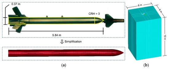
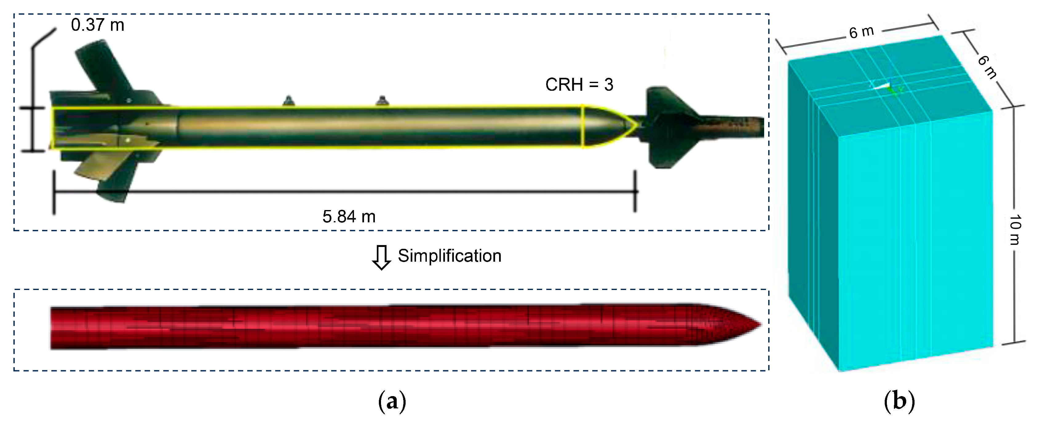
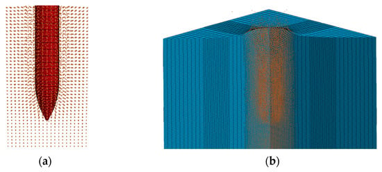
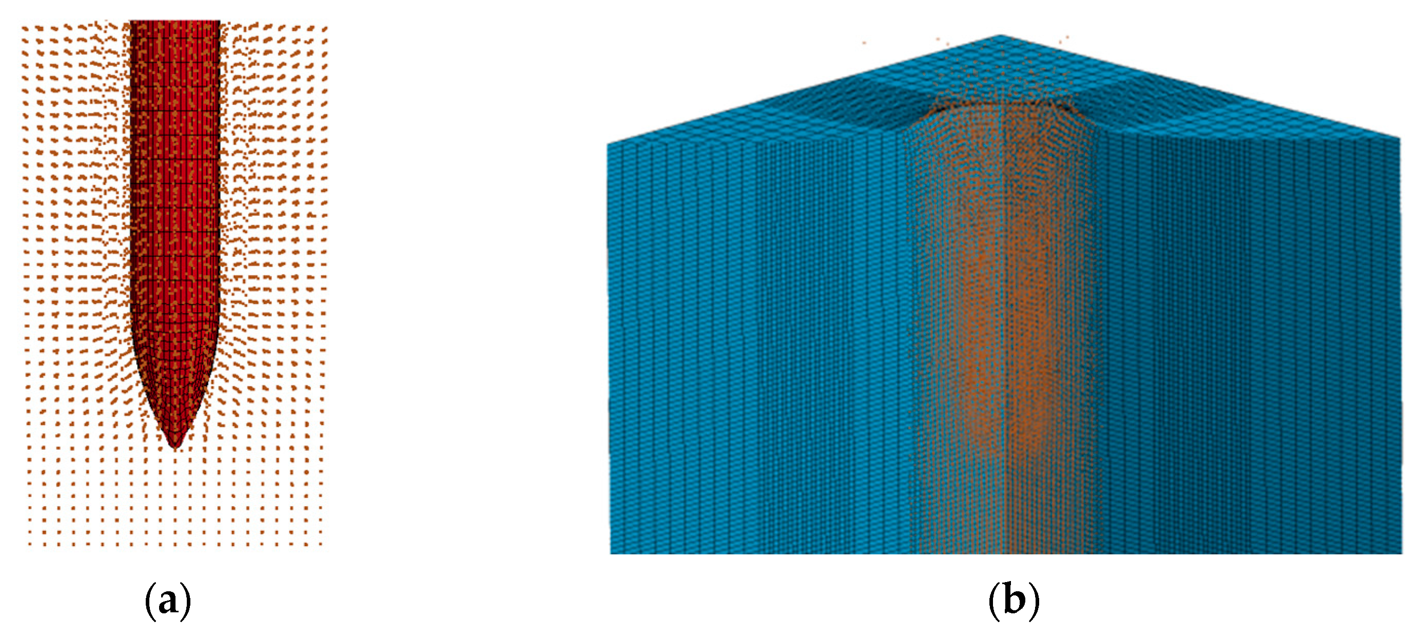
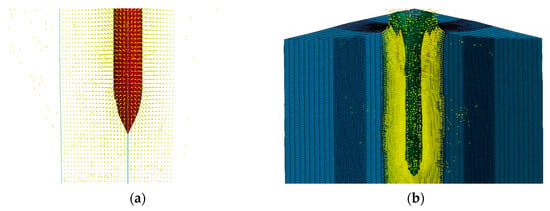
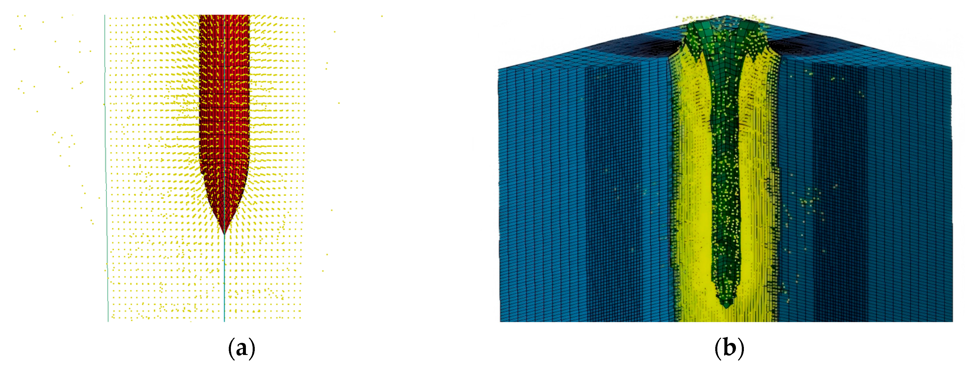
This study employs LS-DYNA software for the numerical simulation of high-speed penetration into plain concrete. The simulation model comprises two main components: a penetrating projectile and a plain concrete target plate. The projectile is modeled after the GBU-28 bunker-buster bomb, with a total length of 5.84 m, a cylindrical section diameter of 37 cm, and a total mass of 230 kg. Its Caliber Radius Head (CRH) value is 3. The projectile geometry was simplified for numerical modeling, as depicted in Figure 1a. The target plate is constructed from concrete. To mitigate boundary effects on the simulation results, the target plate dimensions were set to 6 m in both length and width, and 10 m in depth, as shown in Figure 1b. A target-to-projectile diameter ratio of no less than 15 was maintained to effectively simulate a semi-infinite medium.
Figure 1.
Components of the simulation model: (a) Projectile; (b) Target plate.
2.2. Material Constitutive Model and Parameters
In high-velocity penetration simulations, the selection of appropriate material constitutive models is critical as it directly impacts the accuracy of the computational results. In this study, specific material models were adopted for the tungsten–nickel alloy projectile and the concrete target, respectively.
For the tungsten–nickel alloy projectile, the Johnson–Cook (JC) constitutive model (MAT_015_JOHNSON_COOK) was employed. This model effectively decouples and couples the key mechanical effects during the penetration process, including strain hardening, strain rate strengthening, and thermal softening. This capability makes it highly effective in simulating the failure modes of projectile materials. The Johnson–Cook model is commonly used to describe material behavior under high strain rates, large deformations, and elevated temperatures. Its parameters are listed in Table 1.
Table 1.
Parameters and meanings for tungsten–nickel alloy projectile material.
Considering the strength characteristics of C60 concrete, the KCC (Karagozian & Case Concrete) model, specifically the MAT_072R3 constitutive model, was adopted to simulate the concrete target material. The KCC model demonstrates high accuracy in predicting both penetration depth and cratering morphology. Since the MAT_072R3 model has been calibrated for C60 concrete strength, it allows for the rapid generation of accurate material parameters for simulation. The specific parameters for the concrete target material are presented in Table 2.
Table 2.
Parameters and meanings for concrete target material.
3. Numerical Modelling
3.1. Finite Element Model
3.1.1. Algorithm Overview
The finite element method (FEM) simulates complex physical phenomena by discretizing continuous objects into a large number of interconnected finite elements, which collectively represent the original structure. In high-velocity penetration simulations, an erosion-based failure criterion is typically employed to handle material failure and removal. When the computational results for an element satisfy the predefined failure criterion, the element is considered to have failed, can no longer sustain loads, and is subsequently deleted from the computational model. As the simulation progresses, more elements are removed due to reaching their failure conditions, gradually forming “voids” or “gaps” in the model. This process effectively simulates the material’s erosion, cutting, and penetration. Contact between the projectile and target is typically defined using the *CONTACT_ERODING_SURFACE_TO_SURFACE keyword.
3.1.2. Model Establishment
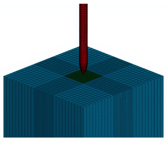
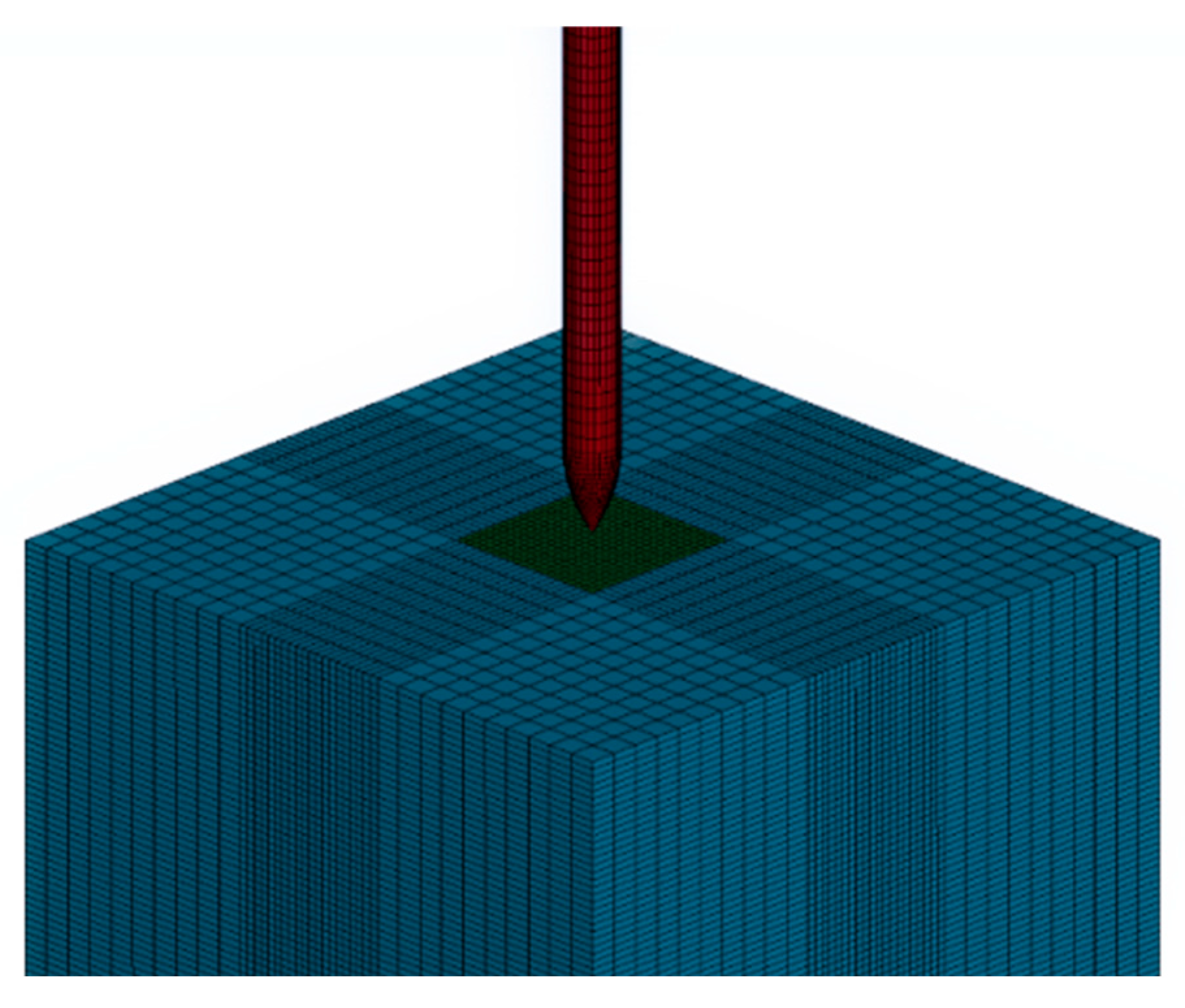
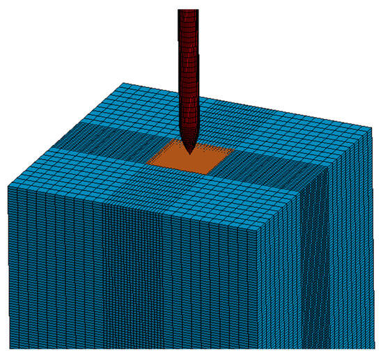
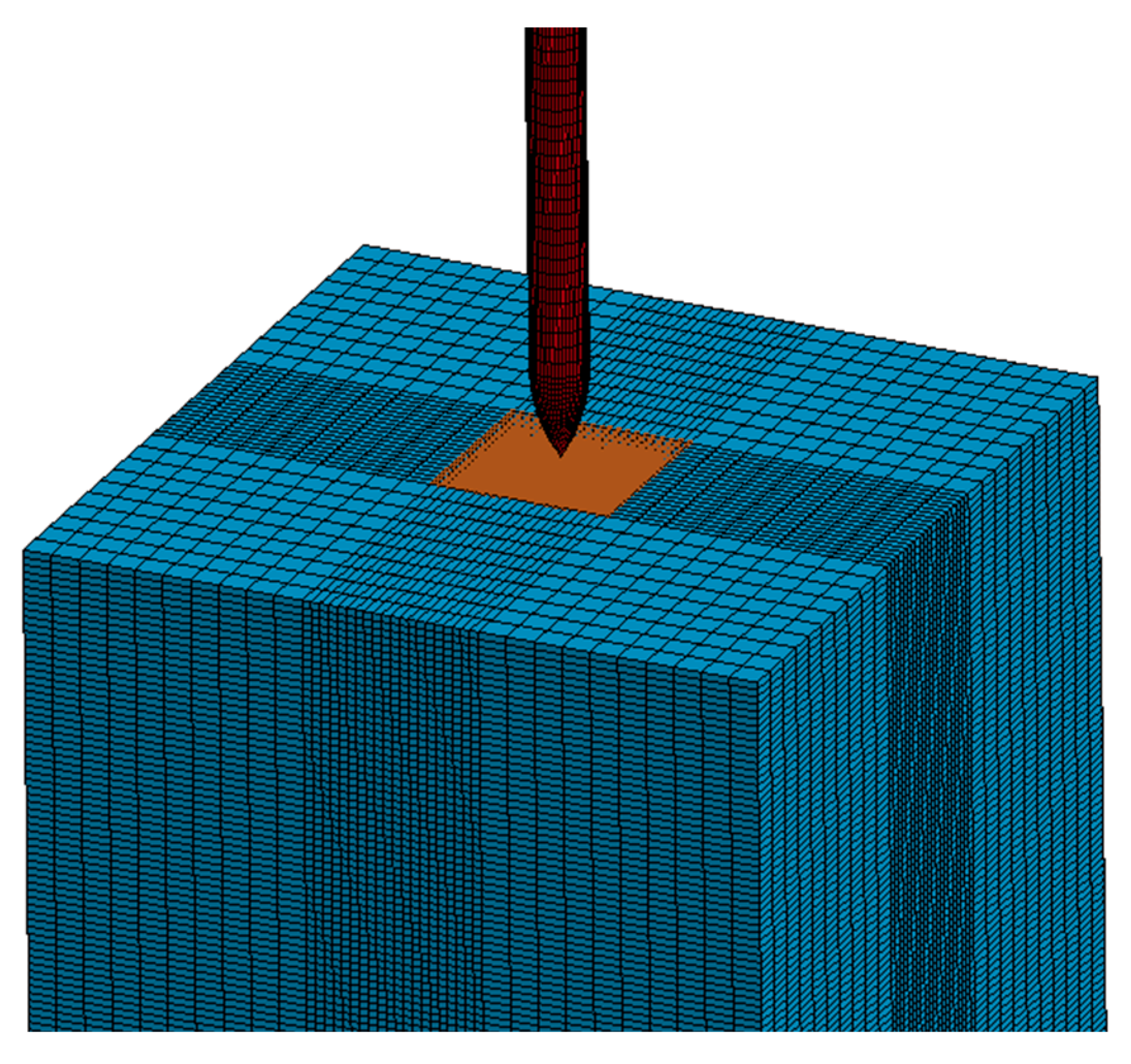
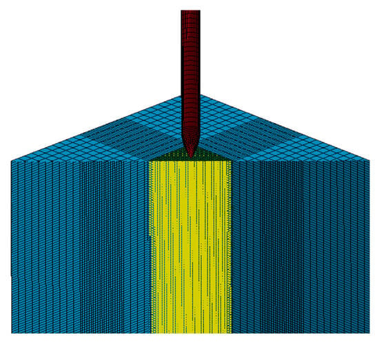
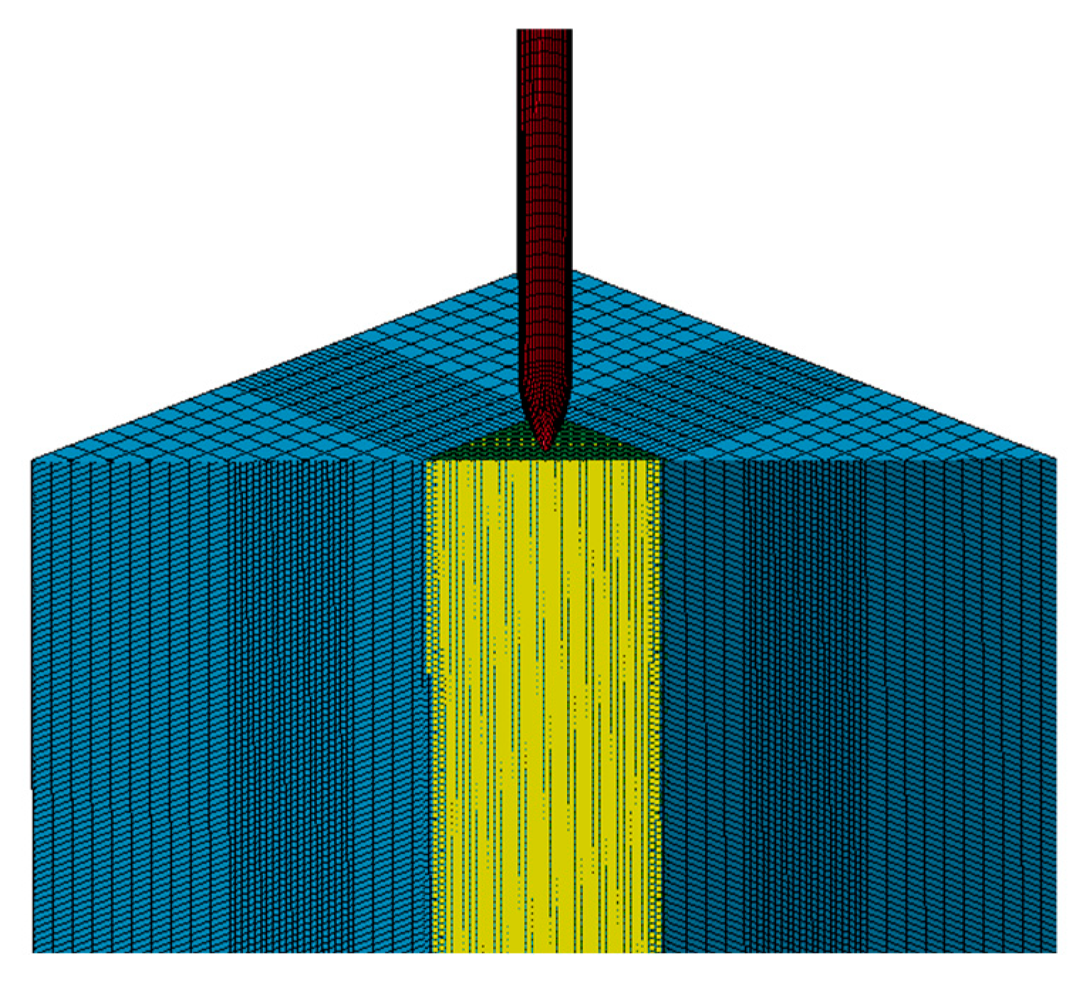
As shown in Figure 2, a traditional finite element method was utilized to establish the model in this study. The target plate was discretized using a multi-level meshing strategy to balance computational cost and numerical accuracy. A high-resolution refined mesh with a characteristic size of 0.06 m was employed in the central 1.2 m × 1.2 m impact region to ensure the spatial resolution of the stress wave propagation and material damage. Furthermore, a gradient mesh refinement was applied to the surrounding areas to maintain topological connectivity and ensure a smooth transition of the numerical solution from the central refined zone to the target boundaries. The contact between the projectile and the target was defined using the *CONTACT_ERODING_SURFACE_TO_SURFACE keyword, while the material failure criteria were set via the *MAT_ADD_EROSION keyword. To simulate a semi-infinite target environment and eliminate artificial wave interference, non-reflecting boundary conditions were applied to the lateral faces of the concrete target using the *BOUNDARY_NON_REFLECTING keyword. Mathematically, this boundary formulation applies a normal impedance-matching stress, σ = −ρcv, where σ is the material density, c is the wave speed, and v is the particle velocity. This ensures that outgoing stress waves are fully absorbed at the boundaries, preventing non-physical reflections from affecting the localized failure dynamics near the penetration path.
Figure 2.
FEM model.
3.1.3. Penetration Process
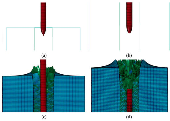
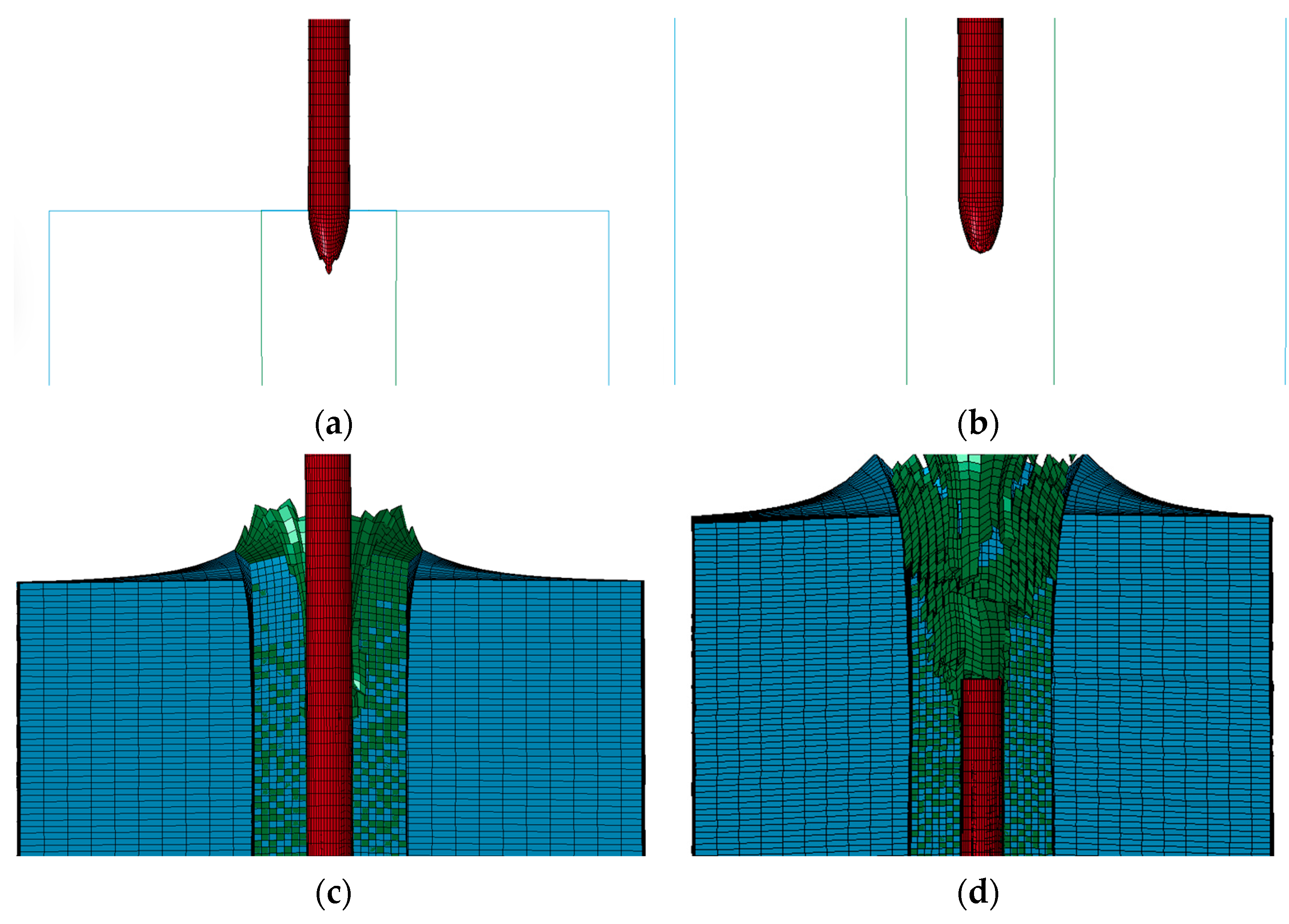
Under a penetration velocity of 600 m/s, the projectile head underwent a certain degree of plastic deformation and cutting upon initial contact with the target. In the early stages of penetration, the projectile head exhibited an irregular shape, as depicted in Figure 3a. As the penetration depth increased, the projectile head further blunted due to the combined effects of thermal softening and cutting, eventually reaching a stable penetration state until the termination of penetration, as shown in Figure 3b. Simultaneously, elements within the concrete target plate were deleted upon satisfying the failure criteria, forming a cavity, as presented in Figure 3c. However, due to the direct deletion of mesh elements, the edges of the cavity appeared somewhat rough, with noticeable depressions and irregularities. As the penetration progressed, the internal structure of the target continued to fail, and the cavity progressively expanded, with its development process illustrated in Figure 3d.
Figure 3.
FEM simulated process of penetration: (a) Early stage; (b) Termination stage; (c) Cavity formation stage; (d) Cavity expansion stage.
3.2. Fixed FEM-SPH Model
3.2.1. Algorithm Overview
The FEM-SPH fixed coupling algorithm addresses the limitations of traditional FEM in handling large deformations and material failure by converting a significant portion of the deforming finite elements in the target into smoothed particle hydrodynamics (SPH) elements. At each time step, the algorithm checks whether any slave node penetrates the master segment. Upon detecting a slave node penetration, the algorithm immediately calculates a contact force, directed along the normal of the master segment, pushing the node back to its original plane. This contact force is then distributed to the relevant slave node and the master nodes of the master segment. After the contact forces are calculated and applied to the relevant nodes, the program solves the dynamic equations, updating the velocities and displacements of these nodes, and subsequently determining the stress/strain states within each element. In every computational cycle, the program verifies if the failure parameters of each element exceed its corresponding failure criterion. Once an element meets the failure conditions, it is marked as “failed,” loses contact with surrounding elements, and is subsequently deleted or destroyed based on predefined criteria.
3.2.2. Model Establishment
Initially, a model is established using the traditional finite element method. Building upon this FEM model, the mesh in the central region of significant deformation is converted into SPH particles at a 100% ratio. The fixed connection between the outer target elements and the SPH particles is defined using the *CONTACT_TIED_NODE_TO_SURFACE keyword. The contact between the projectile and the target is defined using the *CONTACT_ERODING_NODES_TO_SURFACE keyword. Non-reflecting boundary conditions are applied to all four sides of the model to simulate a semi-infinite domain. The specific model setup is illustrated in Figure 4.
Figure 4.
FEM-SPH fixed coupling model.
3.2.3. Penetration Process
Under a penetration velocity of 600 m/s, the projectile head underwent minor deformation during the initial contact. Throughout the subsequent penetration process, the projectile also experienced cutting deformation, but no significant blunting phenomenon was observed, as shown in Figure 5a. As the penetration depth increased, the constraints between SPH particles were progressively broken. Subsequently, these failed SPH particles were ejected as debris, and an internal cavity gradually formed and expanded. The evolution of this cavity is depicted in Figure 5b.
Figure 5.
FEM-SPH fixed coupling simulated process of penetration: (a) Termination stage; (b) Cavity expansion stage.
3.3. Adaptive FEM–SPH Model
3.3.1. Algorithm Overview
The adaptive FEM–SPH algorithm dynamically converts finite elements that undergo large deformations or are about to fail into smoothed particle hydrodynamics (SPH) particles during the simulation. This approach combines the accuracy of FEM in small-deformation regions with the robustness of SPH in large-deformation and fragmentation zones. Conversion criteria are typically based on indicators such as element equivalent plastic strain, strain rate, or damage parameters. For example, an element is flagged as a candidate for conversion when its equivalent plastic strain exceeds a critical value, or its damage parameter exceeds a threshold. Converted SPH particles inherit the mass, momentum, and material properties of the originating element, ensuring conservation of mass and momentum. The method improves the fidelity of penetration, fragmentation, and ejecta prediction while maintaining computational efficiency.
3.3.2. Model Establishment
In this study, the initial model is constructed using FEM, with fine mesh and the adaptive module activated in the central high-strain region. Specifically, the transition from FEM mesh to SPH particles is implemented via the *DEFINE_ADAPTIVE_SOLID_TO_SPH keyword. During the penetration process, elements that undergo excessive distortion—which would otherwise be deleted—are automatically converted into SPH particles. Peripheral FEM elements are retained to preserve global stiffness, and the interface between the peripheral FEM region and the SPH zone is defined by *CONTACT_TIED_NODE_TO_SURFACE. Projectile–target contact is defined by *CONTACT_ERODING_NODES_TO_SURFACE. Non-reflecting boundaries are applied to approximate a semi-infinite domain. The specific model setup is illustrated in Figure 6.
Figure 6.
Adaptive FEM–SPH model.
3.3.3. Penetration Process
Under a penetration velocity of 600 m/s, the adaptive algorithm progressively converts the most deformed regions of the target into SPH particles, avoiding the rough cavity edges produced by direct mesh deletion in conventional FEM. The SPH region naturally captures large deformations, material separation, and ejecta formation. With appropriately chosen conversion thresholds, simulation results for penetration depth, cavity morphology, and ejecta mass distribution show improved agreement with experimental observations. The adaptive approach also reduces the computational overhead compared to full-domain SPH models, balancing accuracy and efficiency. Figure 7 shows the adaptive FEM–SPH simulated process of penetration at the termination and cavity expansion stages.
Figure 7.
Adaptive FEM-SPH simulated process of penetration: (a) Termination stage; (b) Cavity expansion stage.
4. Results and Comparative Analysis
4.1. Typical Empirical Formulas
In the field of high-speed penetration, empirical formulas are crucial tools for predicting projectile penetration depth. These formulas are typically derived from regression analysis of extensive experimental data, offering rapid assessment of penetration phenomena. In this study, the simulation results are compared and analyzed against classical established empirical formulas such as ACE, NDRC, Forrestal, Chen, and Peng to validate the accuracy of the proposed model. Definitions of the symbols involved in these formulas are summarized in Appendix A.
4.1.1. ACE Formula
The ACE (Army Corps of Engineers) formula was developed through regression analysis of high-speed ballistic test data. This formula utilizes a power-law form to effectively correlate the projectile’s kinetic energy characteristics with the target material’s compressive strength and density, thereby providing a concise and efficient prediction of rigid projectile penetration depth. Its expression is as follows:
where P is the penetration depth; d is the projectile diameter; M is the projectile mass; v0 is the initial penetration velocity; and fc is the axial compressive strength of concrete measured from 150 mm × 300 mm cylindrical specimens.
4.1.2. NDRC Formula
The NDRC (National Defense Research Committee) formula is one of the earliest and most widely used empirical formulas in the field of penetration. This formula was initially proposed for concrete target penetration, and its form is as follows:
where G is the dimensionless shock function; and N is the projectile shape coefficient, which is 0.72, 0.84, 1.00, and 1.14, respectively, for flat-nosed, hemispherical, blunt-nosed, and sharp-nosed projectiles.
4.1.3. Forrestal Formula
During the 1980s–1990s, to address the requirements of military protective engineering and weapons effects assessment, Forrestal and his team conducted a series of comprehensive experimental investigations on concrete and rock targets. Their findings revealed that the penetration resistance of rigid projectiles with relatively low length-to-diameter ratios penetrating these target materials exhibits pronounced velocity dependence. Based on the hydrodynamic model for long-rod penetration originally proposed by Tate and Alekseevski, they established a semi-empirical semi-theoretical model for predicting the penetration depth of rigid long-rod projectiles into thick targets, the mathematical form of which is as follows:
where ρt is the concrete density; S is a dimensionless constant representing the penetration resistance of concrete; v1 is the velocity of the projectile as it leaves the crater and enters its trajectory; and ψ is the caliber radius head.
4.1.4. Peng Formula
Based on the dynamic cavity expansion theory, Peng et al. [24] proposed a simple unified penetration model, in which the target resistance term accounts for the influence of the ratio of the projectile diameter to the maximum coarse-aggregate size. The corresponding formula for calculating the penetration depth is given as follows:
where S’ is a material strength parameter, representing the basic resistance that the projectile must overcome during the cratering stage and the initial steady penetration stage; l is the cratering depth; and da,max is the maximum coarse aggregate size in concrete.
To evaluate the predictive accuracy of classical theoretical frameworks, the numerical results were compared against several widely recognized analytical and semi-analytical methods. Among these, the ACE and NDRC formulas treat the penetration depth (DOP) as a combination of power functions involving projectile diameter, mass, impact velocity, and target strength. However, these empirical models neglect the internal stress wave propagation within the target. Furthermore, as they are primarily derived from semi-infinite target designs, they exhibit inherent inaccuracies when predicting scenarios involving boundary effects (i.e., where the ratio of target thickness to projectile diameter is small), as observed in our finite-thickness slab simulations. The Forrestal formula, based on the Cavity Expansion Theory, offers a more mechanistic approach by simplifying the target resistance into a decoupled two-stage process consisting of ‘cratering’ and ‘tunneling’ phases. Yet, in actual penetration events, these two stages are physically continuous and highly coupled, a complexity that a simplified 1D analytical model struggles to capture. Additionally, while the Peng formula demonstrates favorable predictive capabilities for modern high-strength concrete, its reliability is constrained by a specific velocity range (300 m/s to 800 m/s), beyond which the prediction errors increase significantly. In contrast, the numerical approach utilizing the KCC (Karagozian & Case Concrete) model in LS-DYNA overcomes these limitations. It accounts for the dynamic evolution of yield surfaces, pressure-dependent hardening, and rate-sensitive damage, thereby providing a more comprehensive description of the coupled physics that classical formulas simplify or ignore.
4.2. Penetration Depth Comparison Among Different Algorithms
To ensure the credibility of the numerical results and evaluate the sufficiency of the target resolution, the energy balance was strictly monitored throughout the simulation process. Special attention was paid to the hourglass energy to mitigate non-physical modes and ensure velocity convergence. Quantitative analysis shows that even at the peak projectile velocity of 600 m/s, the hourglass energy did not exceed 5% of the total energy. This indicates that the chosen mesh resolution provides a converged and stable solution across the entire investigated velocity spectrum, including the high-speed impact regime.
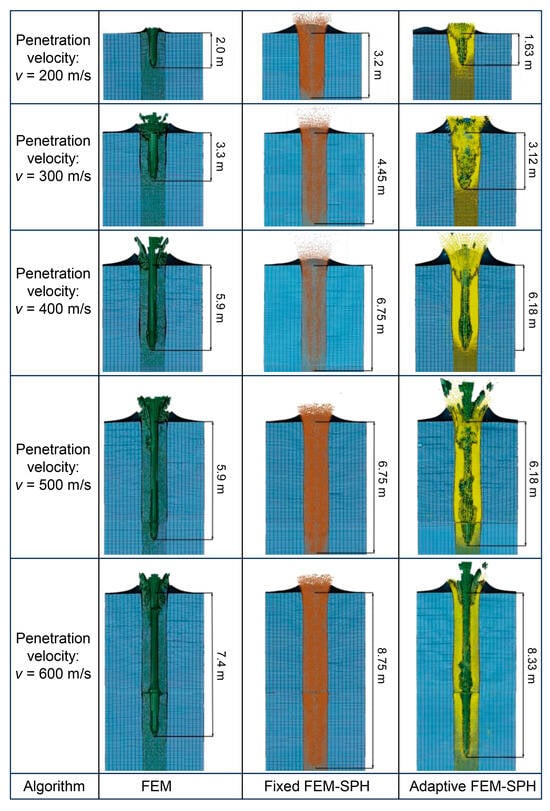
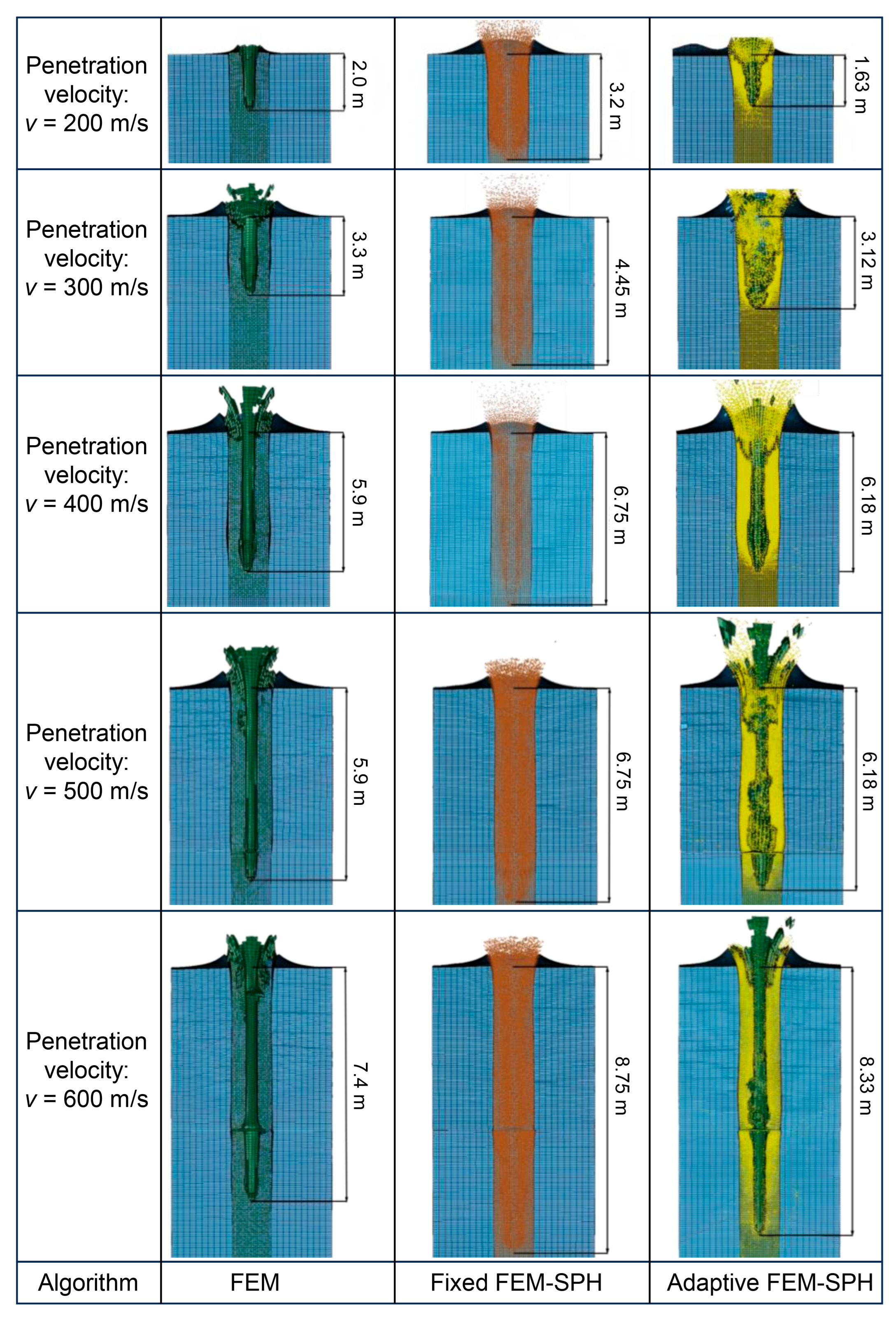
The comparison of penetration depths at different penetration velocities obtained by three algorithms, namely FEM, fixed FEM-SPH, and adaptive FEM-SPH, is shown in Figure 8. It can be observed that as the velocity increases from 200 to 600, the penetration depth of the projectile significantly increases, which is consistent with the fundamental relationship between kinetic energy and penetration depth. Moreover, the growth in penetration depth is not linear, especially in the high-velocity region (e.g., from 500 to 600 m/s), where the rate of increase accelerates, aligning with the trends predicted by existing penetration theories. At lower velocities, the penetration depth obtained by the fixed FEM-SPH algorithm is significantly greater than that of the other two algorithms. However, as the velocity increases, the gap gradually narrows.
Figure 8.
A comparison of the penetration depth at different penetration velocity for different algorithms.
4.3. Penetration Depth Comparison Between Algorithms and Typical Empirical Formulas
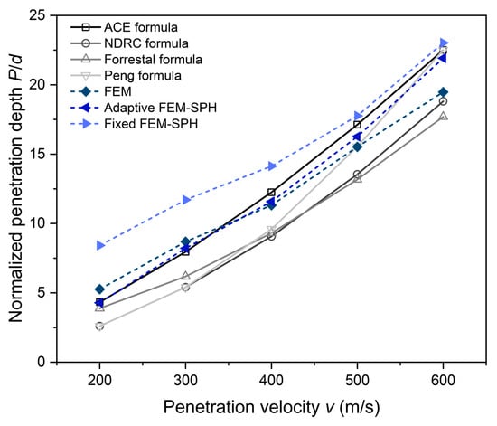
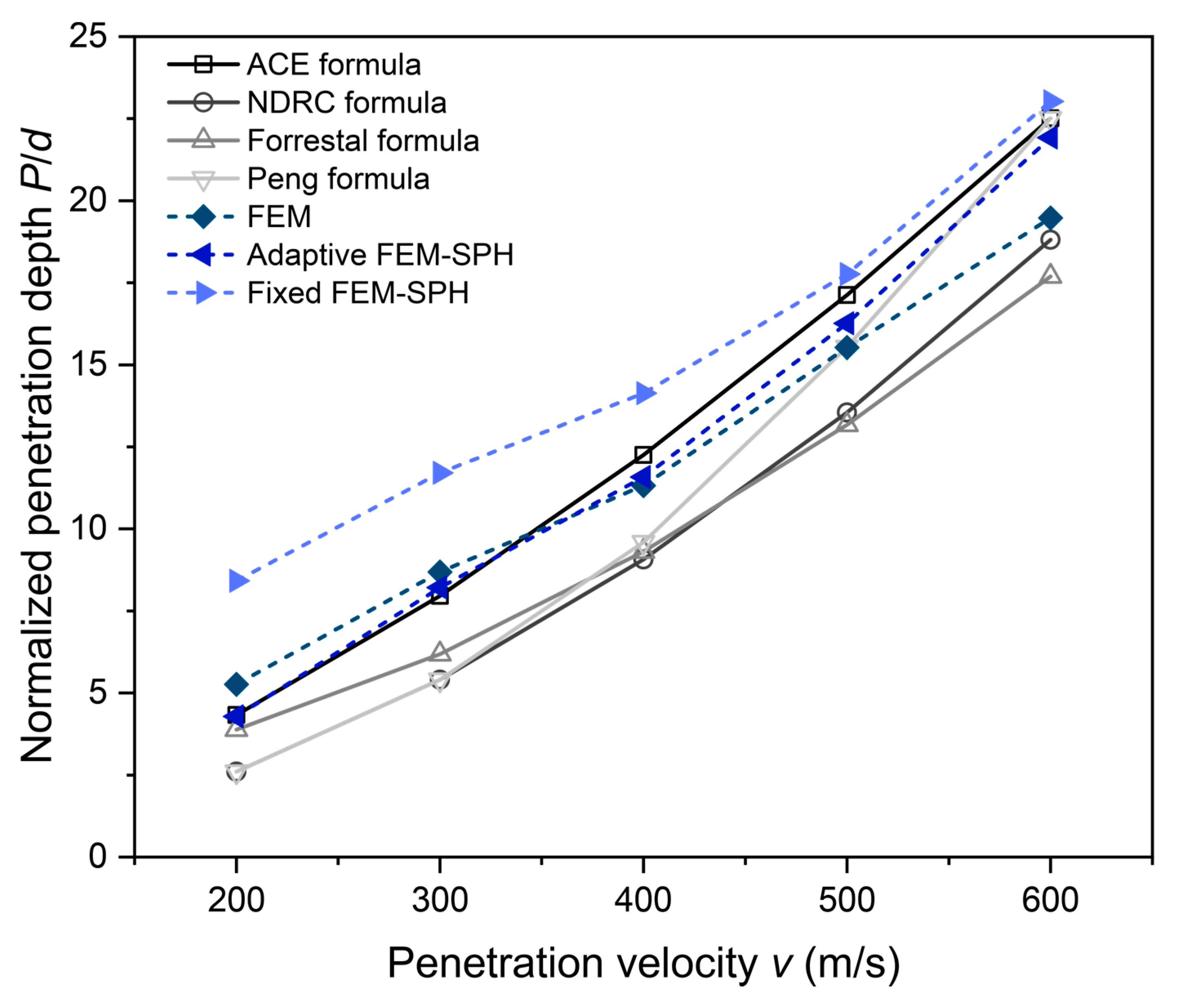
Figure 9 presents the normalized penetration depth (P/d) obtained from the typical empirical formulas and the results simulated by three different algorithms at penetration velocities ranging from 200 to 600 m/s. It can be observed that both the FEM algorithm and the adaptive FEM-SPH algorithm can reasonably describe the general trend of penetration. For the fixed FEM-SPH algorithm, there is a significant discrepancy compared to the predictions of the empirical formula at lower velocities. When the velocity reaches 400 m/s, the results gradually converge toward the accurate values.
Figure 9.
A comparison of the normalized penetration depths between algorithms and typical empirical formulas.
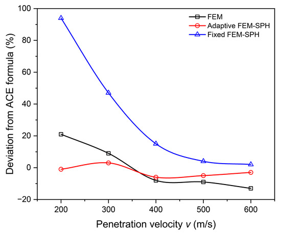
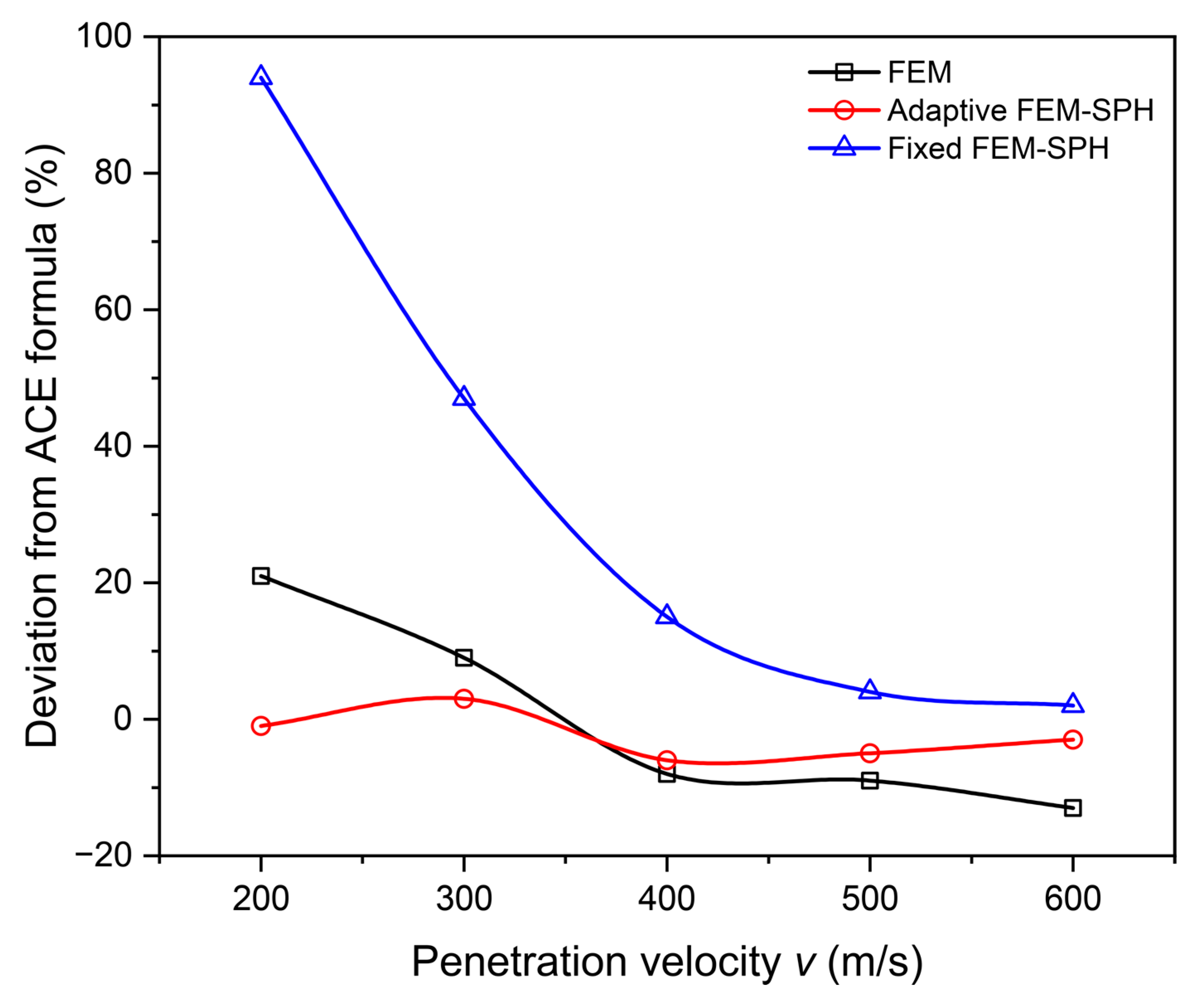
Different empirical formulas exhibit varying prediction accuracies across different penetration velocity ranges. Taking the ACE formula, which provides relatively accurate predictions of penetration depth under multiple conditions, as the benchmark, the simulation accuracy of the three algorithms is compared, as shown in Figure 10. The following observations can be made: The FEM algorithm performs best at velocities around 400 m/s, with a maximum absolute error of 21%. The adaptive FEM-SPH algorithm delivers accurate results across various simulation scenarios and, due to its smoother simulation of the cavity effect, achieves higher precision than the FEM algorithm, with a maximum absolute error of 8%. The fixed FEM-SPH algorithm shows extremely large prediction errors at low velocities; however, as the velocity increases, its simulation accuracy improves progressively. The maximum error decreases from 94% to 15% at 400 m/s, and further reduces to below 5% at 600 m/s.
Figure 10.
Deviation of simulated penetration depths by three algorithms from the ACE formula at different penetration velocities.
Regarding the error issues with the FEM algorithm, the deformation of the projectile shown in Figure 3a indicates a blunting phenomenon at the projectile nose in the simulation results, which differs from existing theories and the results simulated by the FEM-SPH algorithms. Existing theories generally assume the projectile can be treated as a rigid body at velocities below 800 m/s. The damping changes caused by the simulated nose deformation may lead to errors in the results. Furthermore, the mass loss and resistance loss resulting from the deletion of target plate elements could also be reasons why the prediction accuracy of the FEM results is lower than that of the adaptive FEM-SPH algorithm.
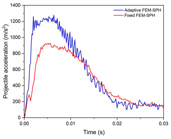
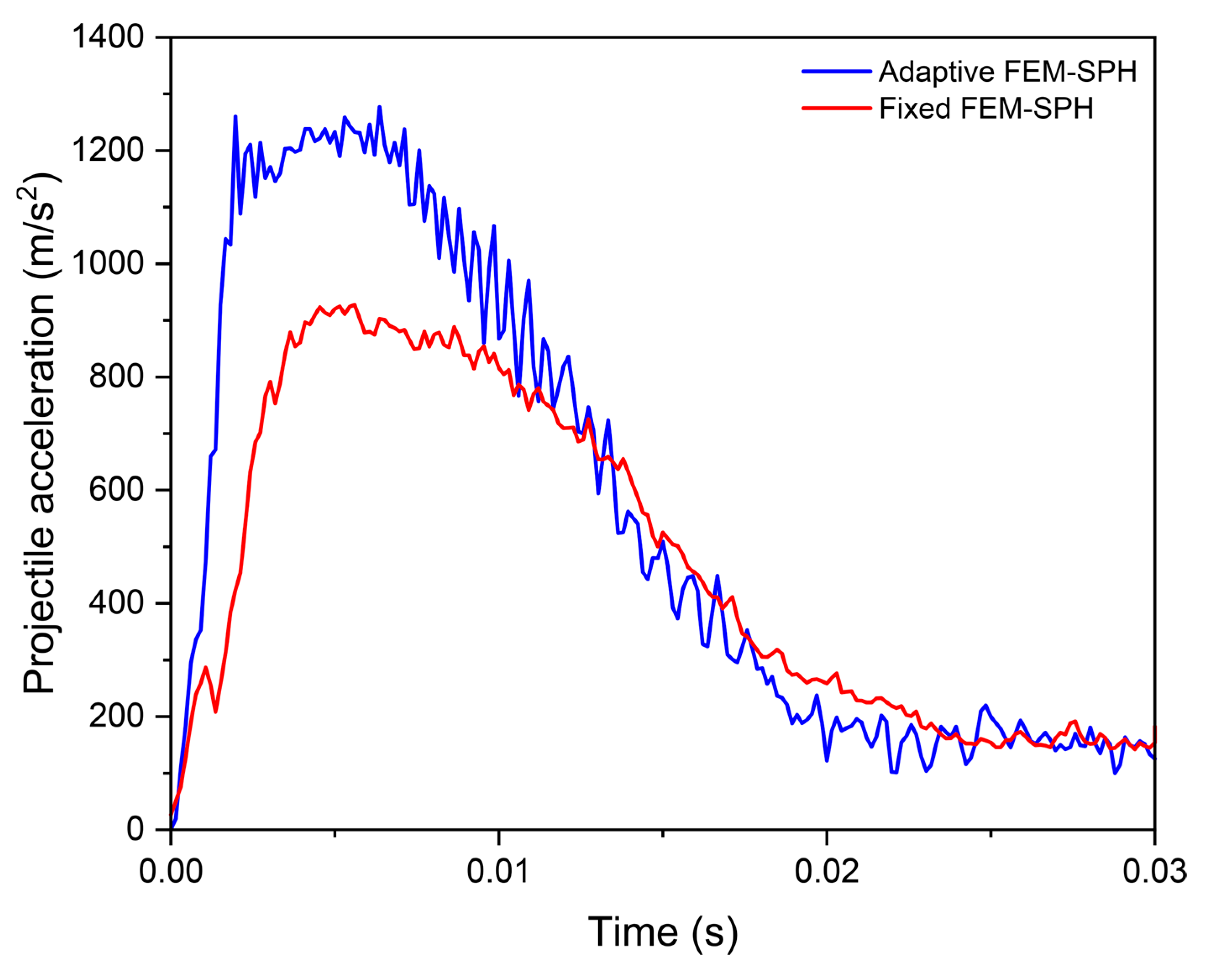
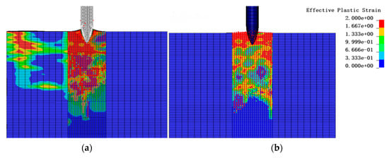
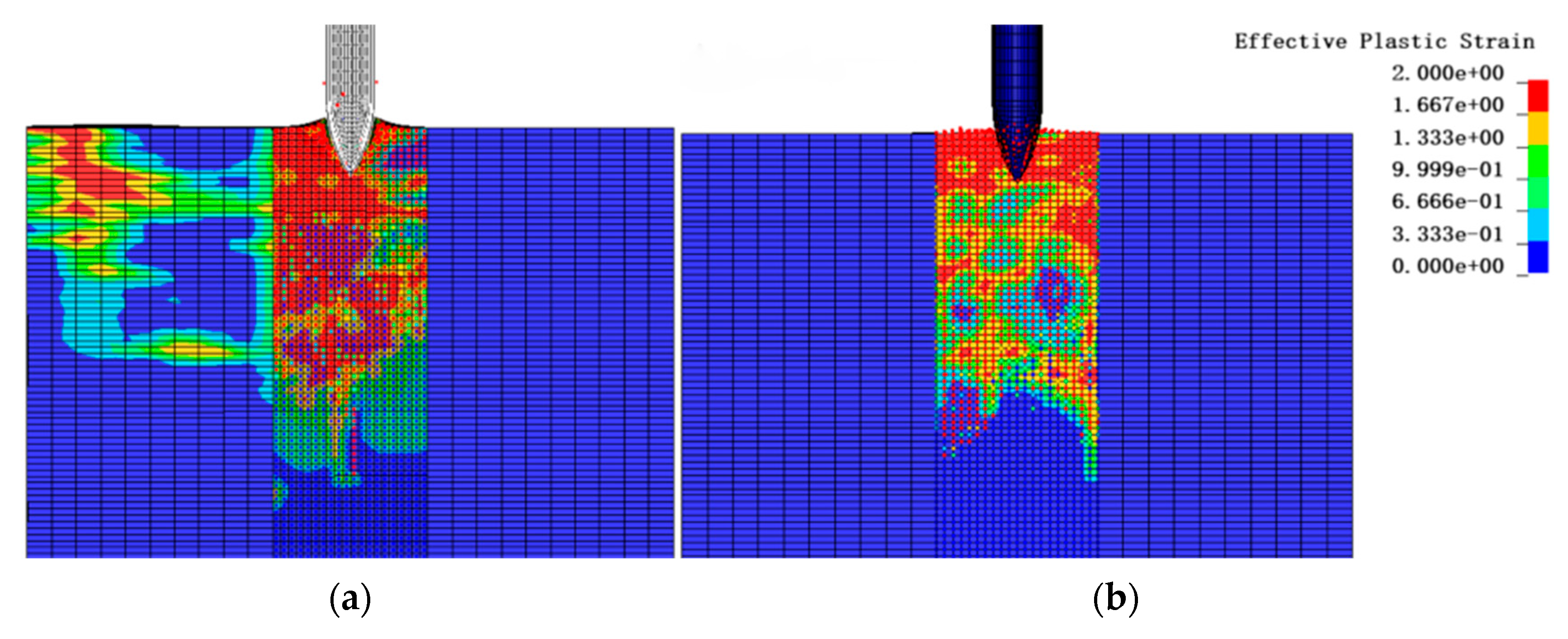
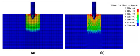
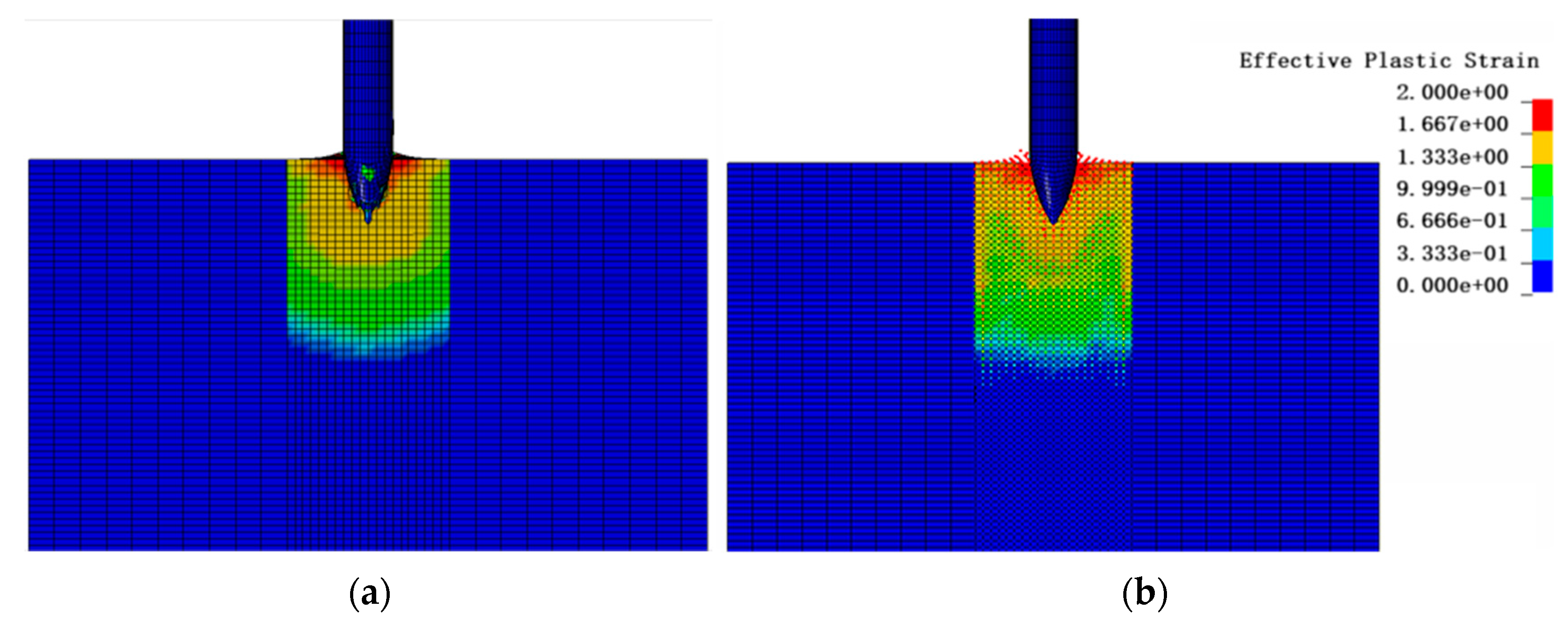
For the fixed FEM-SPH algorithm, an analysis of the projectile acceleration time-history curves obtained from the adaptive FEM-SPH algorithm and the fixed FEM-SPH algorithm, as shown in Figure 11, reveals that the peak acceleration of the fixed FEM-SPH algorithm is significantly lower than that of the adaptive FEM-SPH algorithm. The fluctuations observed in Figure 11 are mainly a numerical/algorithmic effect associated with the adaptive FEM–SPH transition. Combined with the effective plastic strain contours of the target plate at the same moment under 200 m/s for both algorithms, as illustrated in Figure 12, it can be observed that the stress propagation in the fixed FEM-SPH algorithm is slower during the initial stage. Consequently, the concrete within the target plate develops slightly less plastic strain and experiences lower densification. This results in a slower increase in resistance, leading to a slower rise in projectile acceleration. Ultimately, this causes the maximum acceleration to be lower and the overall displacement to be larger.
Figure 11.
Acceleration time-history curves of the projectile obtained by the adaptive FEM-SPH and the fixed FEM-SPH algorithms at penetration velocity of 200 m/s.
Figure 12.
Contours of effective plastic strain in the target plate obtained by the adaptive FEM-SPH and fixed FEM-SPH algorithms at penetration velocity of 200 m/s: (a) Adaptive FEM-SPH; (b) fixed FEM-SPH. (identical scale for (a) and (b)).
As shown in Figure 13, the effective plastic strain contours of the target plate at the same moment under a penetration velocity of 600 m/s are presented for both the adaptive FEM-SPH algorithm and the fixed FEM-SPH algorithm. It can be observed that the two algorithms produce similar distributions of effective plastic strain in the target plate. Correspondingly, the projectile acceleration obtained by the adaptive FEM-SPH algorithm at this moment is −136 m/s2, while that obtained by the fixed FEM-SPH algorithm is −134 m/s2, which aligns with the assumptions made earlier.
Figure 13.
Contours of effective plastic strain in the target plate obtained by the adaptive FEM-SPH and fixed FEM-SPH algorithms at penetration velocity of 600 m/s: (a) Adaptive FEM-SPH; (b) fixed FEM-SPH. (identical scale for (a) and (b)).
4.4. Computation Efficiency Comparison Among Algorithms
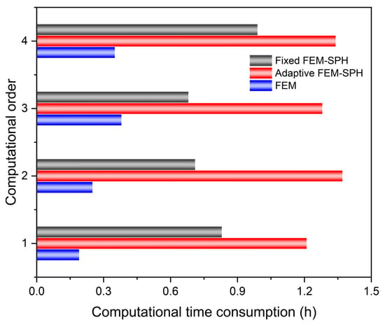
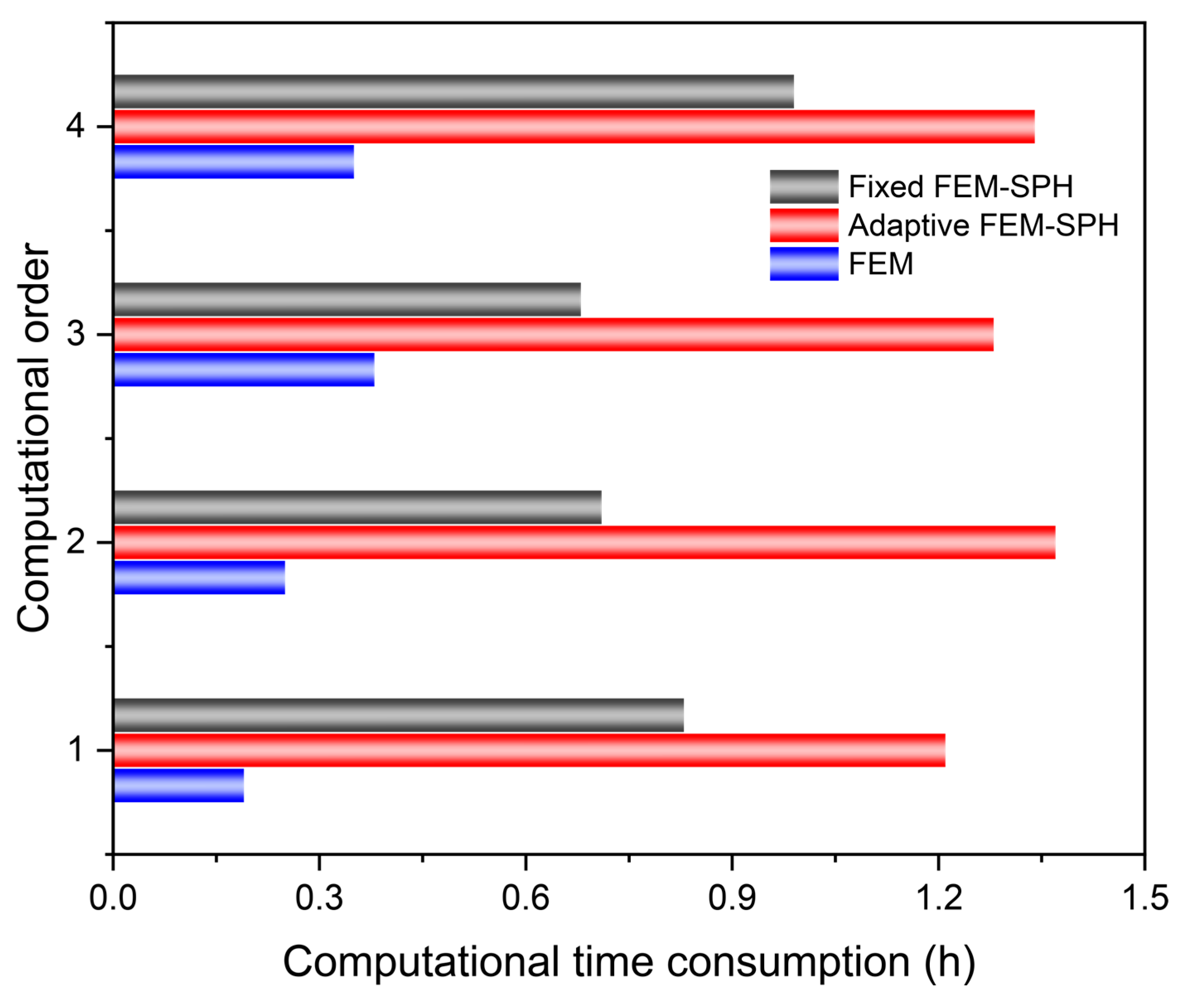
All simulations were performed using 16 CPUs (NCPU = 16) and a memory allocation of 400m (Memory = 400m). The simulations were conducted with a total element count of 96,250, a Termination time of 0.05 s, and a time size of 0.0005 s. Four repeated calculations were performed for the same working condition using the three algorithms, with the computation times shown in Figure 14. It can be observed that the average computation time for the FEM algorithm is 19 min, while the average computation times for the fixed FEM-SPH algorithm and the adaptive FEM-SPH algorithm are 49 min and 1 h 18 min, respectively. The reason for this is that both FEM-SPH algorithms require the calculation of relative positions between a large number of particles and the interaction forces between neighboring particles, resulting in significantly higher computation times compared to the FEM algorithm. Furthermore, in addition to computing particle interactions, the adaptive FEM-SPH algorithm must monitor a large number of mesh elements and convert them into SPH particles upon failure, which leads to an even longer computation time compared to the fixed FEM-SPH coupling algorithm.
Figure 14.
Comparison of computational time consumption at different computational orders among the three algorithms.
5. Discussion
This study aims to evaluate the performances of different numerical algorithms in predicting the penetration depth of high-velocity projectiles into concrete targets, with a focus on comparing the traditional finite element method (FEM), the fixed coupled FEM-SPH model, and the adaptive coupled FEM-SPH model. The results demonstrate that the adaptive FEM-SPH model exhibits better consistency with empirical formula prediction in predicting penetration depth, cavity morphology, and ejecta mass distribution. This is attributed to its capability to dynamically convert mesh elements into SPH particles as needed, thereby more accurately capturing material behavior in regions of large deformation and failure.
To further validate the numerical framework, the results were compared with the experimental and numerical data reported by [25]. In terms of residual velocity prediction, the pure SPH and Adaptive FEM-SPH methods demonstrated high fidelity with errors of 1.03% and 1.76%, respectively, while the conventional FEM showed a substantial discrepancy of 30.5%. Although variations in projectile geometry and material constituents between the two studies inherently affect the absolute results, the overall trend confirms that SPH-based coupling formulations offer a significant advantage in capturing the complex physics of penetration compared to pure Lagrangian FE methods. Detailed sensitivity analyses regarding specific material variations are considered beyond the primary scope of the current algorithmic comparison.
Compared with the traditional FEM approach, although the SPH algorithm results in a significant increase in computational time due to the calculation of interaction forces between neighboring particles, its inherent advantages in handling material failure and large deformation problems make it a powerful tool for high strain rate penetration problems. The fixed coupled FEM-SPH model balances computational efficiency and accuracy to a certain extent, but its predefined SPH region may not fully adapt to the complex material response during the penetration process. The adaptive FEM-SPH model proposed in this study further enhances the model’s adaptability and accuracy by intelligently monitoring a large number of mesh elements and converting them to SPH particles upon failure. Although this adaptive mechanism introduces additional computational overhead, making its computational time potentially slightly longer than the fixed coupled FEM-SPH algorithm, its advantages in improving prediction accuracy are significant. For example, the termination and cavity expansion stages of the adaptive FEM-SPH simulation shown in Figure 7 clearly validate its capability to capture complex physical phenomena.
The results of this study are consistent with previous research, indicating that SPH-based methods possess higher robustness than pure FEMs in high strain rate and material failure problems. The introduction of adaptive strategies, as employed in this work, represents continuous progress in numerical simulation techniques in balancing computational efficiency and accuracy. It not only provides more accurate penetration depth predictions but also more meticulously reproduces the failure patterns and energy dissipation mechanisms of targets during the penetration process.
Although the adaptive FEM-SPH model demonstrates superior performance in terms of accuracy, computational resource consumption remains its primary challenge. Future research directions may include exploring more efficient adaptive criteria, such as machine learning-based optimization of conversion thresholds, to further reduce computational costs. Additionally, by integrating a subsequent series of experimental tests, the model’s applicability can be extended to more complex penetration scenarios—such as multi-layered targets, diverse projectile types, and various target configurations—to further verify its universality. Meanwhile, accurate description of material constitutive models at high strain rates remains crucial for improving simulation accuracy and deserves in-depth investigation in future studies.
6. Conclusions
This work comparatively assesses three numerical approaches, i.e., FEM, fixed FEM-SPH, and adaptive FEM–SPH, for predicting the depth of penetration in plain concrete under high-velocity impact, with emphasis on both accuracy and computational efficiency. Overall, the results show a consistent accuracy–cost trade-off: the adaptive FEM–SPH approach provides the best agreement with reference results, while FEM is the most time-efficient, and fixed FEM-SPH generally lies between them. The conclusions drawn from this study can be summarized as follows.
- The adaptive FEM-SPH algorithm achieves the highest predictive accuracy, with the maximum error remaining below 10% across the investigated velocity ranges, and it better captures strong deformation or damage effects associated with cavity expansion.
- The conventional FEM approach is the most computationally efficient, requiring less than half the runtime of the SPH-involved approaches, but it exhibits the largest deviations, with errors reaching up to about 25% in the considered cases.
- The fixed FEM-SPH algorithm improves prediction accuracy relative to FEM (notably at velocities above 400 m/s), but it requires substantially more computational time due to the added cost of particle interaction calculations.
- From an application perspective, adaptive FEM-SPH is preferable when high fidelity in damage and large-deformation response is required and computational cost is acceptable; FEM is suitable for rapid estimates under tight time/resource constraints; and fixed FEM-SPH provides a practical compromise between accuracy and efficiency.
Author Contributions
Conceptualization, P.G. and Y.W.; methodology, S.W.; software, S.W.; validation, Y.L., Y.W. and P.G.; formal analysis, Y.L.; investigation, S.W.; resources, Y.L.; data curation, S.W.; writing—original draft preparation, P.G.; writing—review and editing, Y.L.; visualization, S.W.; supervision, Y.W.; project administration, Y.L.; funding acquisition, P.G. All authors have read and agreed to the published version of the manuscript.
Funding
This research was funded by the Opening Project of the State Key Laboratory of Explosion Science and Technology (Beijing Institute of Technology), grant number KFJJ25-04M.
Institutional Review Board Statement
Not applicable.
Informed Consent Statement
Not applicable.
Data Availability Statement
The original contributions presented in this study are included in the article. Further inquiries can be directed to the corresponding author.
Conflicts of Interest
The authors declare no conflicts of interest.
Abbreviations
The following abbreviations are used in this manuscript:
| FEM | Finite element method |
| SPH | Smooth Particle Hydrodynamics |
| ACE | Army Corps of Engineers |
| NDRC | National Defense Research Committee |
Appendix A
To further improve clarity and provide a comprehensive reference, a summary table, i.e., Table A1, is provided in this appendix, listing all symbols used throughout the equations in this paper, along with their definitions and, where applicable, their units. This will serve as a quick and easy reference for readers, allowing them to quickly identify the meaning of any symbol.
Table A1.
Symbols used in the equations.
References
- Zhang, S.; Kong, X.; Fang, Q.; Peng, Y. The maximum penetration depth of hypervelocity projectile penetration into concrete targets: Experimental and numerical investigation. Int. J. Impact Eng. 2023, 181, 104734. [Google Scholar] [CrossRef] [Scilit]
- Song, X.; Wang, W.; Deng, Y.; Su, Y.; Jia, F.; Zaheer, Q.; Long, X. Data-driven modeling for residual velocity of projectile penetrating reinforced concrete slabs. Eng. Struct. 2024, 306, 117761. [Google Scholar] [CrossRef] [Scilit]
- Yao, Z.; Qin, F.; Li, J.; Zhang, X.; Huang, F. Experimental and 3D mesoscopic numerical simulation study of kinetic projectile penetrating into concrete. Int. J. Impact Eng. 2025, 195, 105140. [Google Scholar] [CrossRef] [Scilit]
- Wang, W.; Song, X.; Yang, J.; Liu, F.; Gao, W. Experimental and numerical research on the effect of ogive-nose projectile penetrating UR50 ultra-early-strength concrete. Cem. Concr. Compos. 2023, 136, 104902. [Google Scholar] [CrossRef] [Scilit]
- Yang, S.; Kong, X.; Fang, Q.; Peng, Y. Stress waves in concrete targets induced by hypervelocity projectile penetration: An experimental and numerical investigation. Def. Technol. 2025, 53, 31–48. [Google Scholar] [CrossRef] [Scilit]
- Chen, J.; Wei, B.; Xiao, B.; Chen, M.; Zheng, X.; Yang, Z.; Jiang, L. Evaluation of the anti-collision performance of reinforced concrete protective wall for railway bridges under high-speed train impact. Eng. Fail. Anal. 2025, 182, 110097. [Google Scholar] [CrossRef] [Scilit]
- Esaker, M.; Thermou, G.E.; Neves, L. Impact resistance of concrete and fibre-reinforced concrete: A review. Int. J. Impact Eng. 2023, 180, 104722. [Google Scholar] [CrossRef] [Scilit]
- Kılıç, N.; Ekici, B.; Hartomacıoğlu, S. Determination of penetration depth at high velocity impact using finite element method and artificial neural network tools. Def. Technol. 2015, 11, 110–122. [Google Scholar] [CrossRef] [Scilit]
- Zhao, J.; Chen, X.W.; Jin, F.N.; Xu, Y. Depth of penetration of high-speed penetrator with including the effect of mass abrasion. Int. J. Impact Eng. 2010, 37, 971–979. [Google Scholar] [CrossRef] [Scilit]
- Ben-Dor, G.; Dubinsky, A.; Elperin, T. Analytical engineering models for predicting high speed penetration of hard projectiles into concrete shields: A review. Int. J. Damage Mech. 2015, 24, 76–194. [Google Scholar] [CrossRef] [Scilit]
- Gao, F.; Song, C.; Li, G.; Zhang, G.; Deng, S.; Wang, Z.; Liu, C. Experimental and analytical study on the penetration depth of mortar targets subjected to projectile impact in the hypervelocity regime. Int. J. Struct. Stab. Dyn. 2022, 22, 2250069. [Google Scholar] [CrossRef] [Scilit]
- Zheng, J.; Shen, F.; Gu, X.; Zhang, Q. Simulating failure behavior of reinforced concrete T-beam under impact loading by using peridynamics. Int. J. Impact Eng. 2022, 165, 104231. [Google Scholar] [CrossRef] [Scilit]
- Feng, S.; Zhou, Y.; Li, Q.M. Damage behavior and energy absorption characteristics of foamed concrete under dynamic load. Constr. Build. Mater. 2022, 357, 129340. [Google Scholar] [CrossRef] [Scilit]
- Li, C.; Zhi, X.; Song, M.; Lan, C.; Li, S.; Fan, F. Behavior of unbonded prestressed concrete slabs subjected to low-velocity impact loading. Eng. Struct. 2024, 308, 118006. [Google Scholar] [CrossRef] [Scilit]
- Zhao, J.; Jiang, W.; Zhao, L.; Ma, C.; Bu, Q.; Qi, N.; Liu, Y. Finite element analysis of ballistic penetration of trace fragments on aramid UD cloth. Therm. Sci. 2025, 29, 1711–1717. [Google Scholar] [CrossRef] [Scilit]
- Dar, R.U.N.; Alagappan, P. Probabilistic modeling of ballistic penetration in reinforced concrete panels. Struct. Concr. 2025, 26, 4348–4364. [Google Scholar] [CrossRef] [Scilit]
- Eremeyev, V.A.; Balandin, V.V.; Balandin, V.V.; Bragov, A.M.; Konstantinov, A.Y.; Igumnov, L.A. Experimental study and numerical simulation of the dynamic penetration into dry clay. Contin. Mech. Thermodyn. 2023, 35, 457–469. [Google Scholar] [CrossRef] [Scilit]
- Liu, Q.; Hua, J.Y.; Xu, Y.F.; Yang, K.; Cheng, J.C.; Zhang, N.B.; Li, C.; Cai, Y.; Luo, S.N. Ballistic penetration of high-entropy CrMnFeCoNi alloy: Experiments and modelling. Int. J. Mech. Sci. 2023, 249, 108252. [Google Scholar] [CrossRef] [Scilit]
- Zou, G.; Yang, Y.; Wu, S.; Chang, Z.; Liang, Z.; Wang, X.; Zhao, P. Study on the penetration resistance of a honeycomb composite structure coated with polyurethane elastomer. Thin-Walled Struct. 2023, 187, 110747. [Google Scholar] [CrossRef] [Scilit]
- Su, H.; Zhang, C.; Yan, Z.; Gao, P.; Guo, H.; Pan, G.; Wang, J. Numerical Simulation of Penetration Process of Depleted Uranium Alloy Based on an FEM-SPH Coupling Algorithm. Metals 2022, 13, 79. [Google Scholar] [CrossRef] [Scilit]
- Wang, L.; Liu, W.; Wang, G.; Ma, Q. Numerical simulation research of the improved SPH method for projectiles penetrating targets. J. Mech. Sci. Technol. 2025, 39, 7647–7660. [Google Scholar] [CrossRef] [Scilit]
- Liu, X.; Li, J.; Liu, G.; Lian, W.; Yang, H.; Wang, D.; Liu, P. Analysis of FEM-SPH coupling for perforation penetration variation under different geology-engineering conditions. Comput. Part. Mech. 2024, 11, 867–883. [Google Scholar] [CrossRef] [Scilit]
- Yang, W.; Ye, R.; Ren, P.; Tian, A. Antipenetration Performance of Multilayer Protective Structure by the Coupled SPH-FEM Numerical Method. Shock. Vib. 2023, 2023, 6225283. [Google Scholar] [CrossRef] [Scilit]
- Peng, Y.; Wu, H.; Fang, Q.; Gong, Z.M. Geometrical Scaling Effect for Penetration Depth of Hard Projectiles into Concrete Targets. Int. J. Impact Eng. 2018, 120, 46–59. [Google Scholar] [CrossRef] [Scilit]
- He, T.; Wu, W.; Zhu, Y.; Jiang, Y.; Mei, Y.; Lv, Y.; Shao, J.; Sun, Y. Dynamic Response Analysis of Projectile Target Penetration Based on an FE-SPH Adaptive Coupling Method. Metals 2023, 13, 1074. [Google Scholar] [CrossRef] [Scilit]

Disclaimer/Publisher’s Note: The statements, opinions and data contained in all publications are solely those of the individual author(s) and contributor(s) and not of MDPI and/or the editor(s). MDPI and/or the editor(s) disclaim responsibility for any injury to people or property resulting from any ideas, methods, instructions or products referred to in the content. |
© 2026 by the authors. Licensee MDPI, Basel, Switzerland. This article is an open access article distributed under the terms and conditions of the Creative Commons Attribution (CC BY) license.