1. Introduction
Historic masonry retaining walls form an integral part of the built environment in many seismic regions, particularly in historic cities where they support transportation infrastructure, stabilize natural and artificial slopes, and preserve culturally significant landscapes. These structures are commonly constructed using natural stone units bonded with lime- or cement-based mortars and rely primarily on mass and compressive stress transfer to resist gravity loads and lateral earth pressures. Due to their heterogeneous material composition, limited tensile strength, and absence of seismic detailing, historic masonry retaining walls exhibit structural behavior that differs fundamentally from that of modern reinforced retaining systems [
1,
2,
3,
4,
5,
6,
7]. Under seismic excitation, masonry retaining walls are subjected to complex stress states arising from the combined action of axial compression, bending moments, and shear forces induced by gravity loads, earth pressures, and inertial effects. Even moderate seismic demands may lead to the development of tensile stresses that exceed the low tensile capacity of masonry materials, triggering cracking, sliding, or overturning mechanisms. These damage modes are often progressive and may initiate internally before becoming visible, complicating post-earthquake safety assessment. Consequently, the seismic behavior of masonry retaining walls cannot be reliably captured using rigid-body assumptions or overly simplified pseudo-static approaches, highlighting the need for refined analytical methods capable of representing composite material behavior and stress redistribution [
8,
9,
10,
11,
12,
13].
Experimental investigations have consistently demonstrated that masonry and dry-stone retaining walls do not behave as rigid bodies under lateral loading. Instead, their response is governed by internal deformation mechanisms such as sliding along stone interfaces, progressive rearrangement of individual units, and localized stress concentrations within the wall body [
14,
15,
16,
17]. Laboratory tests, centrifuge experiments, and full-scale field studies have further emphasized the importance of stone geometry, interlocking characteristics, and contact conditions between the wall and backfill material in mobilizing frictional resistance and controlling displacement demands under seismic loading [
18,
19]. Field observations following major earthquakes provide additional evidence of the vulnerability of traditional masonry and gravity-type retaining walls. Post-earthquake damage surveys have reported widespread sliding, overturning, and severe cracking in unreinforced masonry retaining structures, whereas reinforced soil and geogrid-supported systems generally exhibit more favorable seismic performance with limited permanent displacements [
20,
21,
22]. Shake-table experiments and dynamic analyses have also shown that classical pseudo-static methods may fail to adequately capture amplification effects, phase differences, and displacement demands induced by real earthquake motions [
23,
24,
25]. To overcome the limitations of simplified analytical approaches, advanced numerical methods based on finite element and discrete element formulations have been increasingly employed. These studies demonstrate that numerical models can successfully reproduce experimentally observed deformation patterns, stress redistribution, and failure mechanisms when material heterogeneity, soil–structure interaction, and nonlinear behavior are appropriately considered [
26,
27,
28]. Recent research has further highlighted the influence of additional factors such as groundwater conditions, traffic loads, surface surcharge, and pre-existing damage on the seismic response of retaining structures, particularly for historic systems [
29,
30,
31,
32].
Despite the extensive body of experimental, numerical, and field-based research, comprehensive numerical investigations focusing specifically on existing historic masonry retaining walls constructed with natural stone and traditional mortars remain limited. In particular, the combined effects of gravity loads, earth pressures, and code-based seismic actions on stress concentration patterns and tensile damage development in such structures have not been sufficiently explored. Moreover, the application of contemporary seismic design regulations to the assessment of existing historic masonry retaining walls requires further investigation [
33,
34,
35,
36,
37,
38].
In this study, the seismic response of historic masonry retaining walls is investigated through a detailed finite element-based numerical framework that goes beyond conventional simplified assessment approaches. Although the seismic behavior of masonry retaining walls has been addressed in previous studies, investigations specifically focusing on historic stone masonry retaining walls within the framework of the Turkish Building Earthquake Code (TBEC-2018) [
39], including its seismic loading and soil–structure interaction provisions, remain limited. To address this research gap, the analysis focuses on the perimeter masonry retaining walls of Emirgan Grove, located in the Sarıyer district of Istanbul, which represent culturally significant heritage structures constructed using natural limestone blocks bonded with cement–lime mortar. The existing geometric configuration, material characteristics, and construction details of the walls are explicitly incorporated into the numerical models, enabling a realistic representation of the actual structural system. Masonry behavior is represented using an anisotropic macro-modeling approach derived from the mechanical characteristics of stone and mortar components, allowing the composite and direction-dependent response of historic masonry to be captured. Vertical loads, earth pressures, and seismic actions are applied in accordance with TBEC-2018, with seismic effects evaluated using the equivalent static earthquake load method. By systematically analyzing representative wall segments with different heights, the study clarifies the influence of wall geometry on seismic response and identifies the governing mechanisms controlling tensile cracking, shear behavior, and overturning under seismic loading. The numerical analyses provide detailed insight into internal force demands, stress distributions, and displacement patterns under combined loading conditions, thereby offering a practical, code-consistent, and preservation-oriented framework for the seismic safety assessment and potential strengthening of existing historic masonry retaining walls.
2. Structural System of the Emirgan Grove Retaining Walls
Emirgan Grove is a historically significant landscape located on the European side of the Bosphorus in the Sarıyer district of Istanbul. The area dates back to the Ottoman period and was incorporated into Ottoman territory in the 17th century, from which it derives its name. During the 19th century, the grove was granted to Khedive Ismail Pasha of Egypt by Sultan Abdülaziz and underwent extensive landscaping works, including the construction of the Yellow, Pink, and White Pavilions, which remain standing today. In the Republican era, Emirgan Grove was transferred to public ownership and preserved as a recreational area while maintaining its historical and natural character. The stone retaining and boundary walls within and around Emirgan Grove were constructed to stabilize the steep topography, create terraced landscapes, and ensure the overall stability of the site. These masonry walls reflect traditional construction techniques and stone workmanship of their period and constitute important engineering elements of the historic landscape. Owing to their age, construction characteristics, and geometric configuration, the retaining walls represent cultural heritage structures that require evaluation in terms of seismic safety. Moreover, their interaction with the underlying soil conditions and the irregular geometry of the terrain may significantly influence their seismic response under strong ground motions [
40,
41].
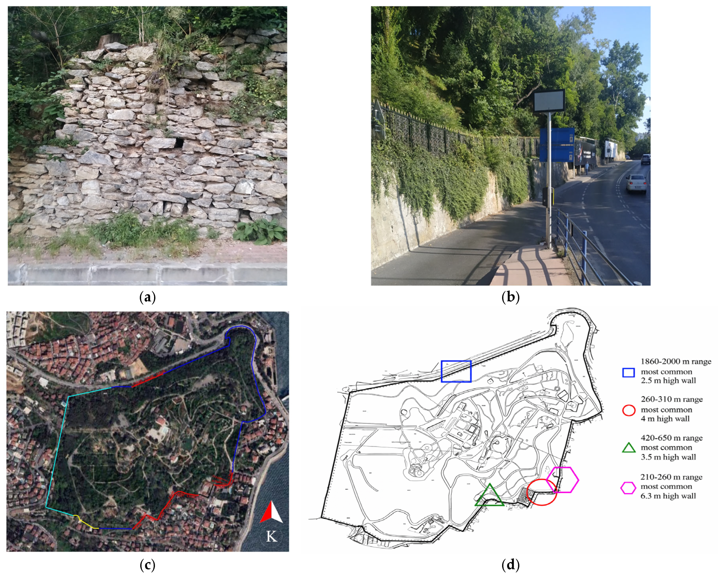
The investigated section is located along the southern boundary of Emirgan Grove, extending across parts of Koru Yolu Avenue, Koru Yokuşu Street, Emirgan Korusu Street, and Katar Avenue, within the Reşitpaşa and Emirgan neighborhoods (
Figure 1). The study area begins at the vehicular entrance on the southern side of the grove and extends westward, terminating approximately 80 m beyond the Emirgan–Reşitpaşa pedestrian entrance. Field observations conducted during site inspections indicate that only certain segments of the perimeter walls exhibit historic masonry characteristics, while other sections were constructed during later periods. These observations form the basis for the selection of representative historic masonry wall segments analyzed in this study. In addition, the proximity of the study area to the North Anatolian Fault system highlights the importance of assessing the seismic performance of these retaining walls within a high seismic hazard context. Furthermore, the variability in wall height, geometry, and construction technique observed along the investigated alignment provides a suitable basis for evaluating the influence of these parameters on seismic response. The selected wall segments therefore allow for a comprehensive assessment of the structural behavior of historic masonry retaining walls under combined static and seismic loading conditions.
The stone retaining and boundary walls surrounding Emirgan Grove consist of masonry structures constructed during different periods to regulate the site’s topography and define its boundaries. Along an approximately 2930 m long alignment, the walls were examined in 20 distinct sections, with heights ranging from about 1.0 m to nearly 6.0 m. The prevailing construction system is unreinforced masonry composed of natural stone units bonded with mortar, while limited horizontal brick courses and reinforced concrete elements were observed in certain sections as later interventions. Field observations indicate that most wall segments are in good to moderate structural condition, requiring only basic maintenance such as vegetation removal and repointing of mortar joints. However, in sections with significant height differences and high backfill and tree-induced loads, damage such as missing stones, deteriorated joints, local deformations, and cracking was identified. These sections were classified as critical zones requiring priority intervention. Given their historical value and existing geometric and structural characteristics, the masonry retaining walls of Emirgan Grove require evaluation of their seismic behavior based on engineering principles. Accordingly, four representative wall segments with different heights (2.5 m, 3.5 m, 4 m and 6.30 m) were selected as critical cases and analyzed in detail under seismic loading.
2.1. Material Properties Used in the Emirgan Grove Wall Model
A total of sixteen core samples were obtained from eight different locations along the walls and tested experimentally. The mechanical properties of the natural stone used in the numerical analyses are summarized in
Table 1.
Based on the experimental investigations, the average uniaxial compressive strength of the examined natural stone samples was determined to be approximately 21 MPa. A review of the literature indicates that the uniaxial compressive strength of natural stone materials generally ranges between 7 and 33 MPa [
42], demonstrating that the experimental results obtained in this study are consistent with previously reported values. The observed scatter in strength values reflects the inherent heterogeneity of natural stone materials, which is commonly attributed to variations in mineral composition, grain structure, and microcrack distribution. According to TS EN 1469 [
43] and TS EN 1467 [
44] standards, a natural rock material intended for use as cladding stone or building stone is required to have a minimum uniaxial compressive strength of 10 MPa. The compressive strength values obtained within the scope of this study exceed the specified minimum limits, indicating that the natural stone used in the Emirgan Grove retaining walls possesses adequate mechanical properties for structural applications. These results further justify the adoption of averaged and conservative material parameters in the numerical analyses conducted in this study.
For the mortar, material properties were adopted from typical experimental results reported in the literature for natural stone mortars. The mechanical properties of the mortar used in the numerical analyses were adopted from representative experimental studies reported in the literature for natural stone mortars [
45]. The mortar was characterized by a compressive strength of 6.6 MPa, a flexural tensile strength of 0.49 MPa, and an elastic modulus of 8.0 GPa. These values are consistent with typical lime- or cement–lime-based mortars commonly used in historic masonry construction. The selected mortar properties reflect a material behavior that is significantly weaker and more deformable than the stone units, allowing for realistic representation of stress redistribution and cracking mechanisms within the masonry assemblage. This modeling approach enables a more accurate simulation of masonry interaction effects and damage evolution under service and seismic loading conditions.
2.2. Emirgan Grove Wall Numaerical Model
The numerical analysis of the Emirgan Grove masonry retaining structure was carried out using a macro-modeling approach, which is commonly adopted for the assessment of masonry systems [
46,
47]. In this method, a representative masonry wall region was defined to reflect the overall structural characteristics of the retaining structure. The stone units and cement–lime mortar within this region were treated as a composite material, and equivalent mechanical properties were derived accordingly. The entire retaining structure was then modeled by assuming that its mechanical behavior could be adequately represented by this equivalent composite section, allowing for an efficient and holistic evaluation of the structural response. In masonry structures, particularly in historic systems requiring repair or strengthening, variations in joint thickness, irregular stone arrangement, and construction interventions carried out over different periods significantly increase the influence of direction-dependent material behavior. The orientation of stone units, the continuity of horizontal mortar joints, and the mechanical contrast between stone and mortar layers lead to different stiffness and strength characteristics in the vertical and horizontal directions. If such systems are modeled assuming isotropic material behavior, the resulting stress distributions and deformation patterns may not accurately reflect the actual structural response.
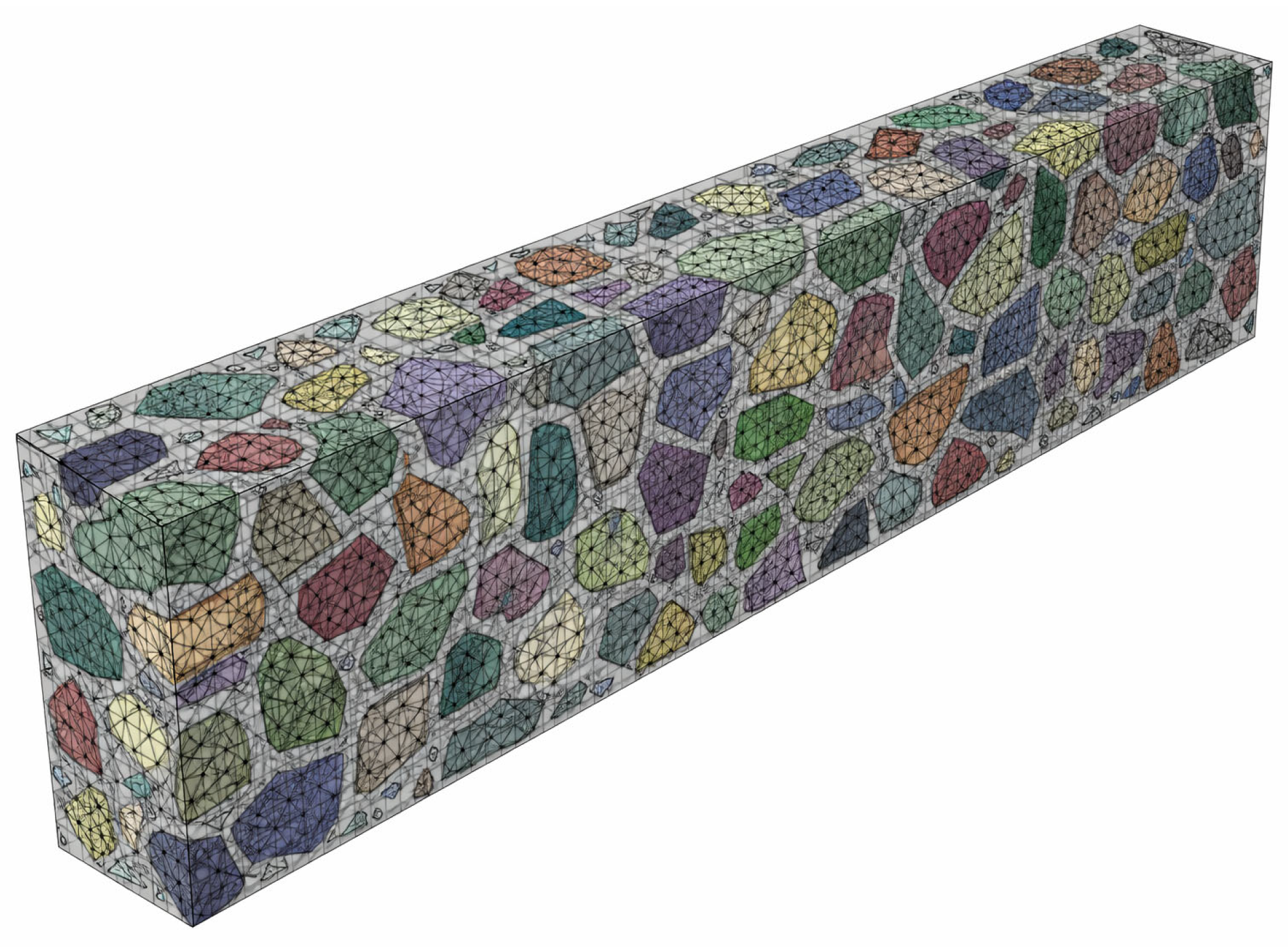
Masonry retaining walls composed of blocks and mortar are inherently anisotropic, as their layered and heterogeneous nature prevents them from exhibiting identical mechanical and thermal behavior in all directions (
Figure 2). Under mechanical and thermal loading, the presence of stone–mortar interfaces and preferential joint orientations causes the material response to vary with direction. Therefore, adopting an anisotropic macro-model enables a more realistic representation of critical mechanisms such as tensile stress development, shear behavior, and crack initiation.
The adopted hybrid micro–macro modeling approach was selected because detailed micro-modeling is not practical for large-scale historic masonry retaining walls, while purely macro-modeling approaches may not sufficiently reflect the influence of material heterogeneity and joint behavior on the structural response. Therefore, micro-scale information reported in the literature was used to inform and calibrate the equivalent anisotropic properties assigned at the macro scale, allowing the composite and direction-dependent behavior of masonry to be realistically represented. Consequently, the use of an anisotropic macro-modeling approach in the numerical analysis of the Emirgan Grove masonry retaining walls provides a more reliable assessment of their structural behavior under seismic and other external actions, while remaining consistent with the actual construction characteristics of historic masonry systems. To determine the elastic modulus values, a micro-scale finite element model of the masonry structure was first developed. At this stage, the limestone units and the cement–lime mortar were defined as separate materials in order to reflect their distinct mechanical characteristics. Although historic stone masonry exhibits inherent material heterogeneity, the resulting elastic properties were intended to represent the average mechanical behavior at the structural scale rather than local variability. The equivalent properties derived from the micro-scale model were therefore used to calibrate the anisotropic parameters adopted in the macro-scale analysis. The selected values fall within conservative ranges commonly reported in the literature and are supported by limited experimental evidence, providing a representative characterization of historic masonry without overestimating structural capacity. Since the numerical analyses focus on seismic response and governing stability mechanisms, this approach allows the effects of material heterogeneity to be reasonably captured in a practical and code-consistent manner. This micro-scale modeling approach allowed the interaction between stone blocks and mortar joints, as well as the effects of joint thickness and material discontinuities, to be explicitly captured. Based on the elastic modulus values obtained at the micro scale, the modeling framework was subsequently extended to a macro-scale finite element model with anisotropic material properties, enabling a realistic representation of the direction-dependent behavior of the masonry system.
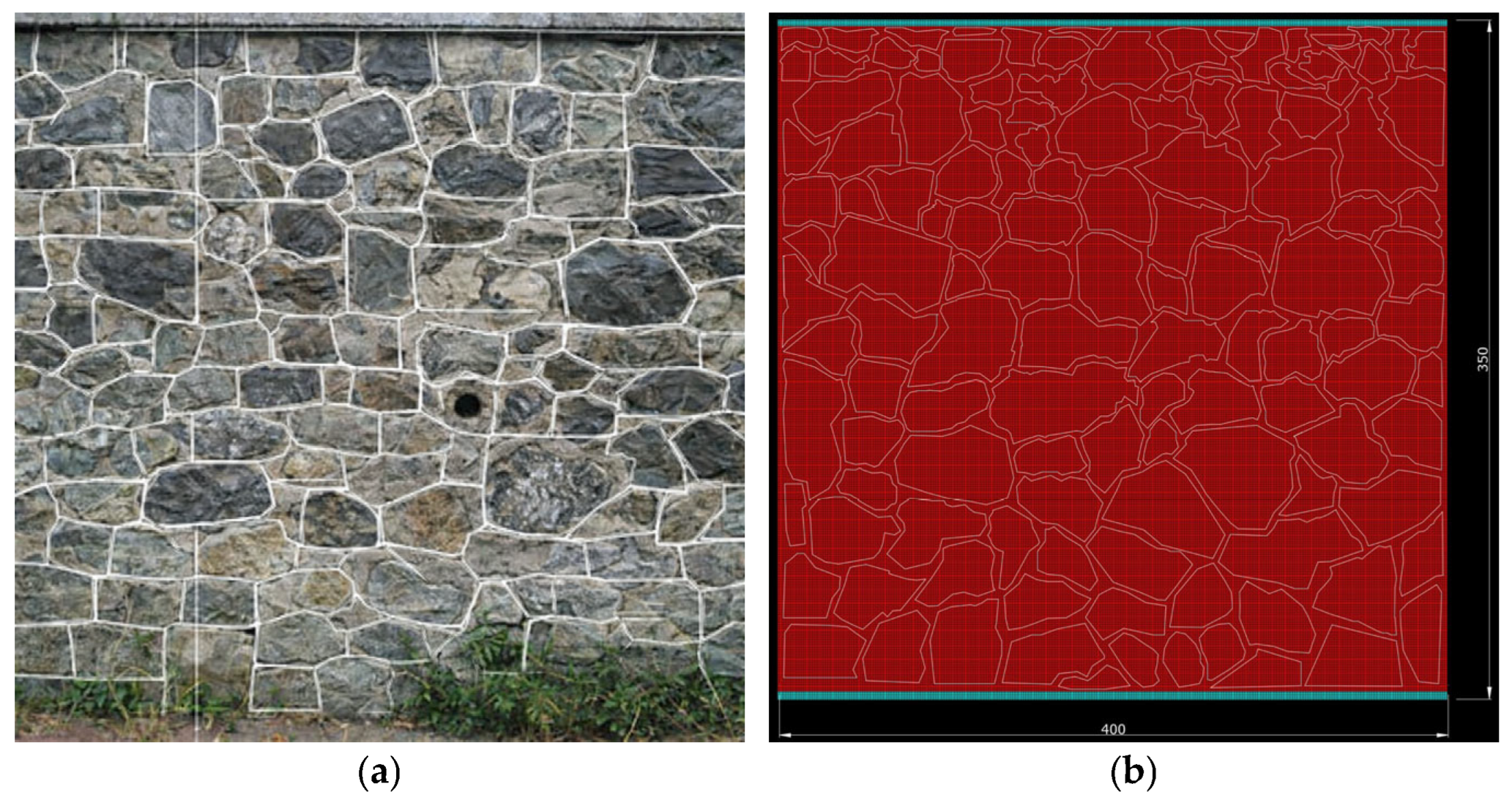
In the finite element modeling, the walls were represented as a masonry assemblage composed of stone blocks and bonding mortar. To ensure uniform and homogeneous load transfer, elastic layers with appropriate mechanical properties were introduced at the top and bottom surfaces of the model. These elastic layers facilitate a more realistic definition of boundary conditions and stress distributions. The limestone blocks were modeled with average dimensions of approximately 40 × 25 × 100 cm and arranged in a staggered pattern with mortar joints varying between 2 and 4 cm in thickness. The overall geometric dimensions of the finite element model were defined in the SAP2000 program as 4.00 × 3.50 m (
Figure 3), and the presence of elastic layers ensured that loads and displacements were distributed uniformly throughout the model. By deriving the elastic modulus at the micro scale and transferring it to the anisotropic macro-scale model, the effective stiffness of the masonry system reflects not only the properties of individual materials but also their structural arrangement and load-transfer mechanisms. This micro-to-macro transition provides a physically consistent basis for the numerical analyses and leads to more reliable predictions of deformation, stress distribution, and overall structural response.
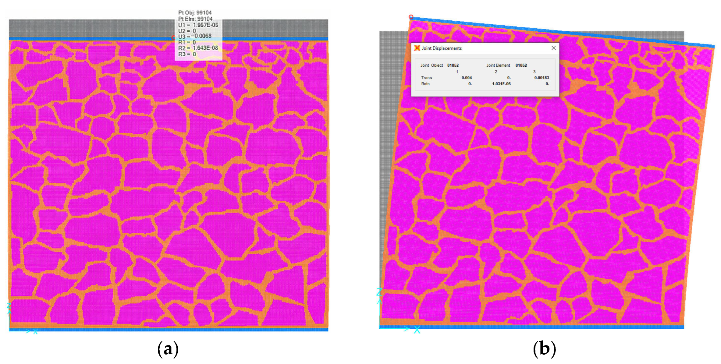
The finite element model, consisting of 58,667 shell elements, was subjected to controlled vertical and horizontal loading schemes to evaluate the elastic and shear stiffness characteristics of the masonry system and to verify the consistency of the elastic modulus transferred from the micro-scale model to the macro-scale representation. For this purpose, a low-magnitude vertical load was first applied to ensure that the structure remained entirely within the linear elastic regime. A nodal load of 300 N was uniformly distributed over the nodes of the elastic layer located at the top of the model, resulting in a total vertical load of 107.7 kN. The magnitude of the applied load was intentionally selected to prevent cracking, damage initiation, or nonlinear material behavior. The resulting vertical displacement of 0.0068 mm (
Figure 4a) confirms that the response of the model was purely elastic and that the adopted elastic modulus was consistently represented at the macro scale.
Subsequently, to assess the horizontal (shear) stiffness of the masonry system, opposing horizontal loads of 10,000 N were applied to the elastic layers located at the top and bottom of the model. In these analyses, the model was restrained only in the vertical direction, while the degrees of freedom in the horizontal direction were preserved. This boundary condition allowed the deformation capacity of the structural element under shear-dominated behavior to be observed without introducing artificial lateral constraints. As a result of the applied horizontal loading, the maximum horizontal displacement was determined to be approximately 0.004 mm (
Figure 4b). The horizontal displacement values obtained from these analyses were used as the basis for evaluating the shear stiffness of the model and for assessing the stiffness characteristics of the masonry structure under lateral loading.
Since the material behavior is direction-dependent (anisotropic), the elastic moduli in the horizontal and vertical directions were calculated using Equations (1) and (2), respectively. By substituting the applied forces, geometric dimensions, and the corresponding displacement values into these equations, the vertical elastic modulus was obtained as E
v = 13,858 N/mm
2, while the horizontal elastic modulus was calculated as E
h = 12,694 N/mm
2.
In the developed wall model, the unit weight of the stone and the cement–lime mortar were defined in the software as 28 kN/m
3 and 21 kN/m
3, respectively. The mass of each shell element was automatically calculated by the program and lumped at the corresponding nodal points. For the natural stone, the Poisson’s ratio was adopted as 0.15 based on values reported in the literature [
48,
49,
50].
By summing the nodal masses, the total mass of the wall model with dimensions of 4.00 m × 3.50 m × 1.00 m was calculated as 32.727 kN·s
2/m, corresponding to a total weight of 321.05 kN. The wall volume was obtained as 14 m
3, based on the geometric dimensions of the model. Accordingly, the average unit weight of the masonry wall was determined as 22.93 kN/m
3 by dividing the total weight by the wall volume. This value is consistent with typical unit weights reported for composite stone masonry walls in the literature [
48,
49,
50], indicating that the adopted material definitions provide a realistic representation of the physical system. Moreover, the close agreement between calculated and expected unit weight values supports the reliability of the mass distribution used in the subsequent static and seismic analyses.
2.3. Geotechnical Assessment
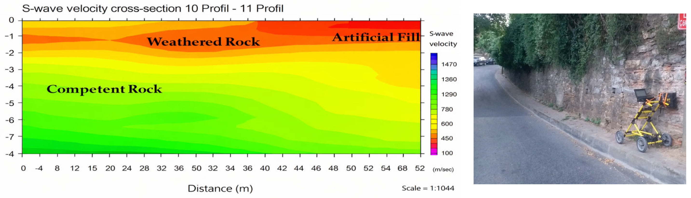
The geotechnical assessment of the stone retaining and boundary walls located within Emirgan Grove was conducted based on field observations, geophysical investigations, and engineering judgment. The subsurface conditions along the wall alignment are characterized by a heterogeneous and layered soil profile, consisting of fill material and topsoil near the surface, underlain by highly weathered to weathered rock layers, and relatively competent rock at greater depths. This complex soil stratification plays a decisive role in the structural behavior and stability of the retaining walls. Geophysical measurements, revealed low to moderate shear-wave velocity (Vs) values within the fill and highly weathered rock layers, indicating reduced stiffness and increased deformation potential. According to the Turkish Building Earthquake Code (TBEC-2018), the foundation soils beneath most wall segments predominantly correspond to ZC soil class, with local transitions to ZB soil class where higher Vs values were observed. No soil conditions corresponding to the ZD class were identified beneath the investigated wall foundations (
Figure 5). The retained backfill materials mainly consist of heterogeneous fill and weathered rock, which impose additional lateral earth pressure and surcharge effects on the walls, especially under seismic loading.
Ground Penetrating Radar (GPR) surveys (
Figure 5) further indicated that the masonry wall thicknesses vary considerably along the site, ranging from approximately 0.60 m to 1.20 m, with locally thicker historical sections reaching up to 1.80–2.00 m. These geometric variations result in non-uniform stiffness and load transfer mechanisms, contributing to localized stress concentrations and differential deformation behavior. Based on the combined evaluation of wall geometry, foundation soil conditions, and backfill characteristics, four retaining walls located at different heights were identified as unfavorable sections. These walls represent the most critical cases due to their greater heights, which significantly increase static and seismic earth pressure demands, as well as their foundation on ZC–ZB class soils with limited stiffness. In addition, the presence of geometric irregularities, heterogeneous backfill materials, and surcharge loads originating from pedestrian use, vegetation, and local service roads further amplifies lateral loading effects. The coexistence of increased wall height, deformable foundation soils, unfavorable backfill conditions, and surcharge effects leads to the most demanding structural scenarios in terms of stability and deformation capacity. Therefore, these four retaining walls were selected as representative unfavorable cases for detailed numerical analysis and seismic performance evaluation.
All soil parameters adopted in the numerical model are summarized in
Table 2. These parameters were selected based on site investigations, geophysical measurements, and the provisions of TBEC-2018. The adopted soil properties reflect the geotechnical conditions of the study area and were used to realistically represent the soil–structure interaction in the numerical analyses. This approach ensures that both static and seismic responses of the retaining walls are evaluated under representative ground conditions.
The geotechnical and soil–structure interaction parameters summarized in
Table 2 were selected based on site investigations, geophysical measurements, and the provisions of the Turkish Building Earthquake Code (TBEC-2018). The unit weight and friction angle of the soil were used to evaluate static and seismic earth pressure components acting on the retaining walls, while the soil–foundation friction parameters directly governed the assessment of sliding resistance at the wall base. The adopted soil class and seismic design parameters (A
0 and SDS) define the seismic hazard level and spectral characteristics of the site, which were used in the determination of equivalent seismic earth pressures. These parameters collectively ensure a realistic representation of soil–structure interaction effects and provide a consistent basis for evaluating the static and seismic performance of the investigated masonry retaining walls.
Soil–structure interaction (SSI) effects were incorporated into the numerical analyses using the site-specific geotechnical parameters summarized in
Table 2 and the code-consistent earth pressure formulations prescribed in TBEC-2018. The interaction between the retaining walls and the surrounding soil was represented by considering active and passive earth pressures, surcharge effects, and base friction resistance, which directly influence sliding and overturning behavior under seismic loading. Although the soil continuum was not explicitly modeled, the adopted SSI representation captures the dominant influence of soil stiffness and strength on the seismic response of masonry retaining walls within the equivalent static analysis framework.
3. Retaining Wall Analysis
The numerical analysis of the structural model was carried out using the SAP2000 v20 software. In order to assess the potential hazard associated with deformations observed in the retaining and boundary stone walls located within Emirgan Grove, all perimeter walls were systematically coded on the site layout plan with a spatial resolution of 10 m, taking a defined reference point as the origin. The continuity of the walls from a static perspective was considered, and the overall system was initially examined using observational assessment methods. Based on the field observations, wall segments that were considered to pose potential static risk were identified. Among these segments, four stone retaining walls located at different positions and identified as being in the most unfavorable conditions were selected for detailed evaluation. These representative wall sections were subsequently analyzed using the finite element method to investigate their structural behavior.
Analysis of Loads Acting on the Retaining Wall
Based on field observations and preliminary static assessments, retaining wall segments that were considered to pose potential structural risk were first identified along the study area. Among these segments, four stone retaining walls with heights of 2.5 m, 3.5 m, 4.0 m, and 6.30 m, located at different positions and representing the most unfavorable conditions in terms of geometry, ground conditions, and loading characteristics, were selected for detailed evaluation. These walls were chosen to represent increasing wall heights and the corresponding variations in earth pressure demands and stability requirements. For each selected retaining wall, all load components acting on the system—including self-weight, static active earth pressure, static active surcharge pressure, static passive earth pressure, and seismic active earth pressure—were calculated separately. The calculated load components were applied to the numerical models as uniformly distributed loads along the wall height and base, consistent with conventional earth pressure theory. The surcharge load (q = 2.0 kN/m2) was adopted to represent pedestrian use and environmental surface loads acting on the backfill.
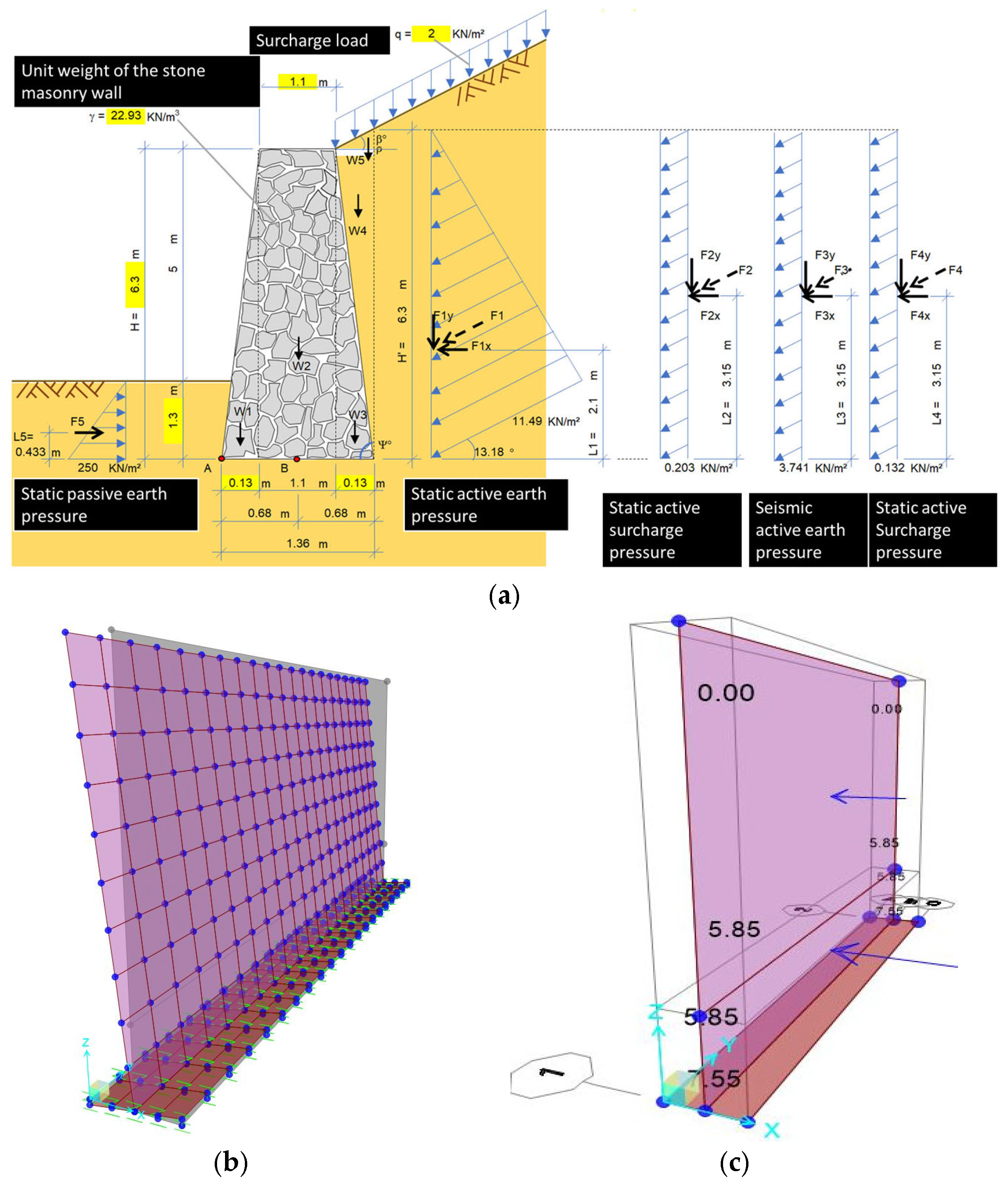
Seismic active earth pressures were evaluated using an equivalent static approach in accordance with the provisions of TBEC-2018, and the contribution of static passive earth pressure at the wall base was considered in the assessment of sliding resistance. All calculated load components were subsequently defined as input parameters in the SAP2000 finite element models, enabling a consistent evaluation of the structural response and stability of the retaining walls under combined static and seismic loading conditions. As a representative example, the detailed load analysis and load distribution corresponding to the 6.30 m high retaining wall, which represents the most critical configuration among the analyzed cases, are presented in
Figure 6.
Figure 6 illustrates the definition of static and seismic loads and their implementation in the finite element model for the 6.30 m high retaining wall, which represents the most unfavorable case among the analyzed configurations. The finite element models were discretized using an element spacing of 0.25 m, which was selected as a compromise between numerical accuracy and computational efficiency, ensuring adequate resolution to capture stress gradients and load distribution along the wall height.
Figure 6a schematically presents the static active and passive earth pressures, surcharge loads, and equivalent seismic loads acting on the wall. Static, active, and passive earth pressures were applied to the numerical models as triangularly distributed loads, whereas the static active surcharge pressure, seismic active earth pressure, and seismic active surcharge pressure were imposed as uniformly distributed loads.
Figure 6b shows the SAP2000 finite element model to which these loads are applied, while
Figure 6c illustrates the definition of these load components along the wall height within the numerical framework.
4. Results
The evaluations were carried out in accordance with the provisions and stress calculation procedures specified in Chapter 11 of the Turkish Building Earthquake Code (TBEC-2018). The internal forces obtained from the shell elements in the SAP2000 v20 structural analysis software were assessed in terms of both force and stress magnitudes, considering axial, compressive, tensile, and shear effects. Based on the internal forces and stresses defined in the program outputs, compressive and shear stresses were calculated and checked against the corresponding limit values prescribed in TBEC-2018. The stresses were derived with respect to the local coordinate systems of the shell elements, as described in the previous section, and were evaluated in terms of normal (tensile/compressive) and shear stress components. In the interpretation of the analysis results, the sign convention of tensile stresses was taken into account, where negative stress values indicate compression, while positive values correspond to tensile stresses. The seismic and static stability analyses of the stone retaining walls were conducted in accordance with the provisions of the Turkish Building Earthquake Code (TBEC-2018). For all wall configurations, static active and passive earth pressures, surcharge-induced pressures, and seismic earth pressure components were evaluated separately using the formulations given in TBEC-2018. The equivalent horizontal and vertical seismic coefficients were taken as kh = 0.1688 and kv = 0.0844, respectively. These coefficients were calculated in accordance with the provisions of the Turkish Building Earthquake Code (TBEC-2018). The horizontal seismic coefficient was defined as kh = SDS/(2.5 × r), using SDS = 0.633 and r = 1.50, which results in kh = 0.1688. The vertical seismic coefficient was taken as kv = 0.5 × kh, giving kv = 0.0844. In TBEC-2018, seismic design inputs are defined through site-specific design spectra derived from probabilistic seismic hazard analysis (PSHA) and are not associated with a single deterministic design earthquake magnitude. For reference, the DD-2 earthquake level defined in TBEC-2018 (10% probability of exceedance in 50 years, corresponding to a 475-year return period) approximately corresponds to a moment magnitude of Mwg ≈ 7.1 for the Marmara region [
51]. Accordingly, the equivalent horizontal and vertical seismic coefficients adopted in this study were computed directly from the TBEC-2018 design spectrum parameters corresponding to the DD-2 earthquake level (10% probability of exceedance in 50 years, i.e., a 475-year return period) and the local site class, following the code-prescribed expressions.
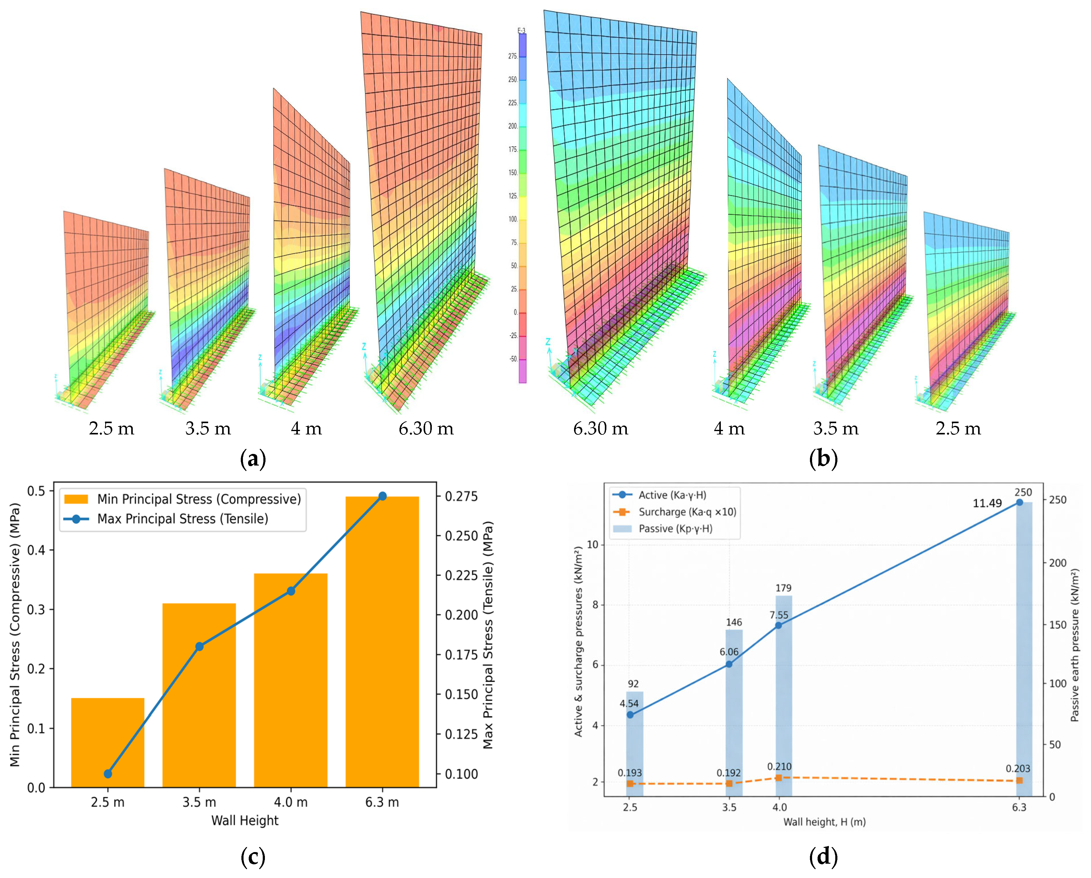
Table 3 and
Figure 7d jointly illustrate the variation of active, surcharge, and passive earth pressure components as a function of wall height. As can be observed, the active earth pressure (Ka.γ.H) increases almost linearly with increasing wall height, which is consistent with classical earth pressure theory. In contrast, the surcharge-induced active pressure (Ka.q) remains nearly constant for all wall configurations, indicating that its contribution to the total lateral pressure is independent of wall height and relatively small in magnitude. The passive earth pressure (Kp.γ.H′), however, exhibits a significantly steeper increase with wall height, reaching substantially higher values compared to the active components. This pronounced growth highlights the dominant role of passive resistance, particularly for higher walls with greater embedment depths. Overall, the combined evaluation of the tabulated results and graphical representation demonstrates that while active pressures govern the loading demand, passive pressures play a critical role in stability and resistance mechanisms as wall height increases.
For the 2.5 m high retaining wall, the calculated static active earth pressure coefficient remained relatively low, and both overturning and sliding safety factors were well above the minimum limits prescribed by TBEC-2018 under all loading conditions. The wall exhibited a stable response under static, static + seismic, and seismic-only loading cases, indicating sufficient resistance against both sliding and overturning. In the case of the 3.5 m high retaining wall, seismic effects became more pronounced. While the wall satisfied the stability requirements for static and static + seismic loading conditions, the overturning safety factor under the seismic-only loading case locally approached or fell below the code-specified limit. This behavior indicates that, for intermediate wall heights, seismic effects may govern overturning checks even when sliding stability remains adequate. For the 4.0 m high retaining wall, the static active earth pressure coefficient increased to approximately Ka ≈ 0.105, resulting in higher lateral pressure demands. Nevertheless, the calculated passive earth pressure coefficient (Kp ≈ 11.07) provided a significant stabilizing contribution. Both overturning and sliding safety factors exceeded the minimum requirements of TBEC-2018 for all loading cases, with an overturning safety factor of approximately 2.18, indicating a stable structural response without the need for additional strengthening. The 6.30 m high retaining wall, representing the most critical configuration, exhibited the highest static and seismic earth pressure demands due to increased wall height. Despite this increase, the combined contribution of base friction resistance and passive earth pressure ensured that sliding stability conditions were satisfied for all load combinations. Overturning safety checks confirmed that stabilizing moments exceeded overturning moments for static and static + seismic cases, while remaining close to the allowable limits under seismic-dominant conditions. Overall, the comparative evaluation demonstrates that wall height is the primary parameter governing the seismic response of stone retaining walls, particularly with respect to overturning behavior. As a result of the analyses, the distributions of the maximum (tensile) and minimum (compressive) principal stresses developed in four retaining structures with different dimensions were obtained using the macro-modeling technique (
Figure 7a,b). The macro-modeling approach adopted in the finite element analysis of unreinforced masonry structures is defined in the Turkish Building Earthquake Code (TBEC-2018), in which masonry is represented as an equivalent homogeneous continuum with averaged mechanical properties, enabling an efficient and code-consistent evaluation of stress redistribution and deformation behavior under seismic loading. In
Figure 7a,b, the color scale represents the magnitude of the principal stresses, where warm colors (red to yellow) indicate higher stress levels and cool colors (green to blue) correspond to lower stress values. Positive values of the maximum principal stress denote tensile stresses, while negative values of the minimum principal stress represent compressive stresses. All stress values are expressed in MPa. The retaining structures with different dimensions selected in this study generally represent the characteristics of the existing walls located in Emirgan Grove. Moreover, these structures correspond to the most structurally vulnerable examples within their respective groups.
When the retaining walls are evaluated in terms of compressive stresses, it is observed that the maximum compressive stress occurs in the wall with a height of 6.30 m, reaching approximately 0.48 MPa. These compressive stress values are significantly lower than the allowable compressive stress of 4.50 MPa. Therefore, the retaining structures exhibit a high level of safety with respect to compressive stresses. In terms of tensile stresses, the maximum tensile stress is also observed in the 6.30 m high wall, with a magnitude of approximately 0.28 MPa. Since the obtained tensile stress values are lower than the allowable tensile stress of 1.00 MPa, it can be stated that the retaining walls have sufficient thickness to prevent the development of critical tensile stresses. When the retaining walls are examined with respect to shear stresses, the highest shear stress is again observed in the 6.30 m high wall, with a value of approximately 0.25 MPa. These shear stress values exceed the allowable shear stress of 0.10 MPa. It is observed that the shear stresses are concentrated mainly along the soil–wall interface on the front face of the walls.
The exceedance of allowable shear stress limits observed in taller masonry retaining walls indicates the potential initiation of localized damage, particularly along the soil–wall interface, where stress concentrations develop under seismic loading. From a structural assessment perspective, this behavior does not imply instability of the retaining wall system, but rather highlights critical regions that may be susceptible to local cracking or sliding. Therefore, this finding should be interpreted as an assessment-related concern for existing historic masonry retaining walls rather than a design deficiency. The results emphasize the importance of identifying vulnerable zones and, where necessary, implementing localized strengthening or soil–wall interface improvement measures to mitigate seismic damage while preserving the original structural configuration.
The numerical results indicate that wall height is the dominant parameter governing the seismic response and stability of historic masonry retaining walls. As the wall height increases, static and seismic earth pressure demands become more significant, leading to increased tensile and shear stress concentrations, particularly near the base and along the soil–wall interface. While compressive stress levels remain well below the allowable limits for all analyzed configurations, overturning behavior becomes critical under seismic loading in taller walls. In contrast, sliding stability is consistently ensured in all analyzed cases due to sufficient base resistance and the mobilization of passive earth pressure. These findings demonstrate that seismic vulnerability in masonry retaining walls is primarily controlled by geometric configuration rather than compressive capacity, highlighting the importance of detailed numerical assessment for reliable seismic safety evaluation.
5. Conclusions
This study investigated the seismic performance of historic masonry retaining walls through a finite element-based numerical framework that explicitly accounts for anisotropic masonry behavior, soil–structure interaction, and code-consistent seismic loading. Representative wall segments with heights of 2.5 m, 3.5 m, 4.0 m, and 6.30 m, selected from the perimeter retaining walls of Emirgan Grove in Istanbul, were analyzed under combined static and seismic loading conditions in accordance with the Turkish Building Earthquake Code (TBEC-2018). By adopting the anisotropic macro-modeling approach defined in TBEC-2018 and integrating site-specific geometry and material characteristics, this study provides a practical and regulation-consistent methodology for the seismic assessment of existing historic masonry retaining walls. Based on the numerical results, the following conclusions can be drawn:
This study demonstrates, through a TBEC-2018-based anisotropic macro-modeling framework, that wall height is the dominant parameter governing the seismic response and stability of historic masonry retaining walls, with increasing height leading to significantly higher static and seismic earth pressure demands and increased overturning susceptibility.
The numerical analyses confirm that active earth pressures increase approximately linearly with wall height, in agreement with classical earth pressure theory, while surcharge-induced pressures remain nearly constant and contribute marginally to the overall lateral load demand.
A major contribution of this study is the explicit quantification of the stabilizing role of passive earth pressure, which increases markedly with wall height and provides a substantial contribution to sliding resistance, particularly for taller walls with greater embedment depths.
The results show that sliding stability is consistently ensured in all analyzed cases, even under seismic loading, due to the combined effects of base friction resistance and mobilized passive earth pressure, highlighting a key distinction between sliding and overturning performance in historic masonry retaining walls.
The study identifies overturning behavior, rather than sliding, as the governing seismic stability mechanism for intermediate and tall masonry retaining walls, providing important insight for seismic safety evaluation and retrofit prioritization.
Computed compressive stresses remain well below the allowable limits prescribed by TBEC-2018, demonstrating a high safety margin against compressive failure and confirming that compressive capacity is not a controlling factor in the seismic performance of the investigated walls.
Tensile stress demands do not exceed allowable tensile stress limits, indicating that the existing wall thicknesses are generally sufficient to prevent critical tensile cracking under the considered loading scenarios.
An important outcome of the macro-modeling approach is the identification of localized shear stress concentrations, particularly along the soil–wall interface in taller walls, indicating that shear behavior may govern damage initiation under seismic loading and should be carefully considered in preservation-oriented strengthening strategies.
The study confirms the effectiveness of the TBEC-2018-defined anisotropic macro-modeling approach in capturing internal stress redistribution and identifying critical regions susceptible to seismic damage in historic masonry retaining walls.
Overall, this research highlights the necessity of detailed finite element-based numerical analysis for historic masonry retaining walls, as simplified rigid-body or pseudo-static approaches are insufficient to capture governing failure mechanisms and seismic vulnerability.
From a practical perspective, the results indicate that wall height is a key parameter in the seismic assessment of historic masonry retaining walls. Walls exceeding approximately 4.0 m in height showed increased susceptibility to overturning and localized shear damage, indicating that such structures should be prioritized in seismic inspection and assessment programs. In particular, the soil–wall interface and lower regions of taller walls emerge as critical inspection zones due to recurring stress concentrations. These findings support the use of height-based screening criteria and targeted strengthening strategies for existing historic masonry retaining walls.
The results should also be interpreted considering certain limitations. The numerical analyses were conducted using site-specific material and geotechnical parameters representative of the Emirgan Grove retaining walls, and different soil conditions or masonry typologies may lead to different seismic responses. In addition, the analyses were based on two-dimensional numerical models and an equivalent static seismic approach, which may not fully capture three-dimensional effects, post-cracking behavior, or dynamic soil–structure interaction.
Within the scope of this study, the equivalent static method was considered appropriate for evaluating global stability, stress demand, and governing failure mechanisms of existing masonry retaining walls, in full compliance with the provisions of TBEC-2018. Although the equivalent static analysis approach adopted in this study is fully consistent with TBEC-2018 provisions and is suitable for evaluating global stability and stress demand, near-fault ground motions characterized by pulse-like effects may impose increased displacement demands, particularly in taller masonry retaining walls. Therefore, for near-fault scenarios expected in the Marmara Sea region, complementary nonlinear analyses may be required to further assess displacement-based performance and post-cracking response. Future studies may extend the proposed numerical framework by incorporating nonlinear material behavior, more advanced soil–structure interaction models, and time-history analyses using recorded near-fault and far-field ground motions. In addition, the effectiveness of different strengthening and retrofit techniques, such as localized shear strengthening or anchorage systems, could be investigated within the same modeling framework, supported by experimental validation studies on representative masonry wall specimens.
Author Contributions
Conceptualization, M.Ö. and Y.B.A.; methodology, M.Ö.; software, M.Ö.; validation, M.Ö., Y.B.A.; formal analysis, Y.B.A.; investigation, Y.B.A.; resources, Y.B.A.; data curation, M.Ö.; writing—original draft preparation, M.Ö.; writing—review and editing, M.Ö.; visualization, Y.B.A.; supervision, M.Ö. All authors have read and agreed to the published version of the manuscript.
Funding
This research received no external funding.
Institutional Review Board Statement
Not applicable for studies not involving humans or animals.
Informed Consent Statement
Not applicable for studies not involving humans.
Data Availability Statement
The raw data supporting the conclusions of this article will be made available by the authors on request.
Conflicts of Interest
The authors declare no conflicts of interest. The funders had no role in the design of the study; in the collection, analysis, or interpretation of the data; in the writing of the manuscript; or in the decision to publish the results.
References
- García, J.M.; Bonett, R.L.; Schultz, A.E. Structural testing of ungrouted post-tensioned cantilever masonry walls under unidirectional out-of-plane monotonic and cyclic loading. Eng. Struct. 2021, 235, 111961. [Google Scholar] [CrossRef]
- Savalle, N.; Monchal, C.; Vincens, E.; Forcioli, S.; Lourenço, P.B. Static and seismic design of dry stone retaining walls following Eurocode standards. Eng. Struct. 2023, 274, 114847. [Google Scholar] [CrossRef]
- Ertugrul, O.L.; Trandafir, A.C.; Ozkan, M.Y. Reduction of dynamic earth loads on flexible cantilever retaining walls by deformable geofoam panels. Soil Dyn. Earthq. Eng. 2017, 92, 462–471. [Google Scholar] [CrossRef]
- Guan, X.; Madabhushi, G.S.P. Effect of water table on the behaviour of retaining walls and adjacent structures during earthquake loading. Soil Dyn. Earthq. Eng. 2025, 191, 109273. [Google Scholar] [CrossRef]
- Khalifa, M.A.; El Naggar, M.H. Dynamic p–y curves for flexible retaining walls in dry sand. Soil Dyn. Earthq. Eng. 2026, 200, 109766. [Google Scholar] [CrossRef]
- Tripura, D.D.; Kasinikota, P. Axial load behavior of unreinforced and reinforced hollow interlocking compressed stabilized earth block masonry walls. Constr. Build. Mater. 2023, 407, 133451. [Google Scholar] [CrossRef]
- Lan, G.; Gao, T.; Shi, S.; Yu, W.; Jin, L. Seismic behavior of interlocking compressed earth block walls strengthened with a steel-strap frame system. Constr. Build. Mater. 2025, 502, 144486. [Google Scholar] [CrossRef]
- Wu, P.; Tan, D.; Lin, S.; Chen, W.; Yin, J.; Malik, N.; Li, A. Development of a monitoring and warning system based on optical fiber sensing technology for masonry retaining walls and trees. J. Rock Mech. Geotech. Eng. 2022, 14, 1064–1076. [Google Scholar] [CrossRef]
- Dinç-Şengönül, B.; Yüzer, N.; Şengönül, C.; Ulukaya, S.; Oktay, D.; Ündül, Ö. Behavior of grout injected solid stone masonry walls under in-plane loading. Structures 2023, 58, 10541. [Google Scholar] [CrossRef]
- Huang, J.; Yang, X.; Chen, G.; Wu, W.; Li, H.; Yu, X.; Wang, J. Strengthening methods of stone masonry structures: A critical review. Structures 2026, 83, 110870. [Google Scholar] [CrossRef]
- Huamani, K.; Enciso, R.; Gonzales, M.; Zavaleta, D.; Aguilar, R. Experimental and numerical evaluation of a stackable compressed earth block masonry system: Characterization at cyclic shear loads. J. Build. Eng. 2022, 60, 105139. [Google Scholar] [CrossRef]
- Wondolowski, M.; Hain, A.; Motaref, S. Experimental evaluation of 3D imaging technologies for structural assessment of masonry retaining walls. Results Eng. 2024, 21, 101901. [Google Scholar] [CrossRef]
- Dewoolkar, M.M.; Ko, H.-Y.; Pak, R.Y.S. Seismic behavior of cantilever retaining walls with liquefiable backfills. J. Geotech. Geoenviron. Eng. 2001, 127, 424–435. [Google Scholar] [CrossRef]
- Villemus, B.; Morel, J.C.; Boutin, C. Experimental assessment of dry stone retaining wall stability on a rigid foundation. Eng. Struct. 2007, 29, 2124–2132. [Google Scholar] [CrossRef]
- Vincens, E. Dry stone retaining walls. In Rock Mechanics and Rock Engineering: From the Past to the Future; CRC Press: London, UK, 2012; pp. 1–48. [Google Scholar]
- Colas, A.-S.; Morel, J.-C.; Garnier, D. Full-scale field trials to assess dry-stone retaining wall stability. Eng. Struct. 2010, 32, 1215–1222. [Google Scholar] [CrossRef]
- Quezada, J.-C.; Vincens, E.; Mouterde, R.; Morel, J.-C. 3D failure of a scale-down dry stone retaining wall: A DEM modelling. Eng. Struct. 2016, 117, 506–517. [Google Scholar] [CrossRef]
- Fukumoto, Y.; Yoshida, J.; Sakaguchi, H.; Murakami, A. The effects of block shape on the seismic behavior of dry-stone masonry retaining walls: A numerical investigation by discrete element modeling. Soils Found. 2014, 54, 1117–1126. [Google Scholar] [CrossRef]
- Savalle, N.; Vincens, E.; Hans, S. Pseudo-static scaled-down experiments on dry stone retaining walls. Eng. Struct. 2018, 171, 336–347. [Google Scholar] [CrossRef]
- Tatsuoka, F.; Tateyama, M.; Koseki, J. Performance of soil retaining walls for railway embankments. Soils Found. 1996, 36, 311–324. [Google Scholar] [CrossRef] [PubMed]
- Pan, H.; Akbar, M.; Arshid, M.U.; Mazhar, Z.B.; Guoqiang, O.; Alshammari, T.O.; Yosri, A.M. Seismic resilience of geogrid reinforced concrete earth-retaining wall. Structures 2025, 71, 107901. [Google Scholar]
- Ma, L.; Huang, M.; Han, L. Time-history dynamic characteristics of reinforced soil-retaining walls. Shock Vib. Dyn. Mech. 2024, 18, 851–873. [Google Scholar] [CrossRef]
- Öztürk, M.; Karan, M.A. Impact of Near-Fault Seismic Inputs on Building Performance: A Case Study Informed by the 2023 Maras Earthquakes. Appl. Sci. 2025, 15, 10142. [Google Scholar] [CrossRef]
- Liu, S.-H.; Jia, F.; Chen, X.-L.; Li, L.-J. Experimental study on seismic response of soilbags-built retaining wall. Geotext. Geomembr. 2020, 48, 603–613. [Google Scholar] [CrossRef]
- Tricarico, M.; Madabhushi, G.S.P.; Aversa, S. Centrifuge modelling of flexible retaining walls. Soil Dyn. Earthq. Eng. 2016, 88, 297–306. [Google Scholar] [CrossRef]
- Salem, A.N.; Ezzeldine, O.Y.; Amer, M.I. Seismic loading on cantilever retaining walls. Soil Dyn. Earthq. Eng. 2020, 130, 105962. [Google Scholar] [CrossRef]
- Sharma, S.; Longo, M.; Messali, F. Analysis procedures for masonry earth retaining structures. Eng. Struct. 2024, 315, 118420. [Google Scholar] [CrossRef]
- Akbar, M.; Pan, H.; Huang, J.; Ahmed, B.; Ou, G. Influence of earth-retaining walls on dynamic response. Comput. Model. Eng. Sci. 2024, 139, 2835–2870. [Google Scholar]
- Hidayati, A.M.; Prabandiyani, S.R.W.; Redana, I.W. Slide surface of gravity retaining walls. Procedia Eng. 2015, 125, 338–344. [Google Scholar] [CrossRef]
- Tiwari, R.; Lam, N. Displacement based seismic assessment of retaining walls. Acta Geotech. 2022, 17, 3675–3694. [Google Scholar] [CrossRef]
- Sharma, S.; Longo, M.; Messali, F. Tier-based numerical analysis of masonry quay walls. Front. Built Environ. 2023, 9, 1194658. [Google Scholar] [CrossRef]
- Lew, M.; Simantob, E.; Hudson, M.B. Performance of shored earth retaining systems during the January 17, 1994, Northridge earthquake. In Proceedings of the Third International Conference on Recent Advances in Geotechnical Earthquake Engineering and Soil Dynamics, St. Louis, MO, USA, 2–7 April 1995. [Google Scholar]
- Conte, E.; Troncone, A.; Vena, M.; Chatterjee, K.; Singh, A.P. A method for the design of embedded cantilever retaining walls under static and seismic loading. Géotechnique 2017, 67, 939–952. [Google Scholar] [CrossRef]
- Konai, S.; Sengupta, A.; Deb, K. Seismic behavior of cantilever wall embedded in dry and saturated sand. Front. Struct. Civ. Eng. 2020, 14, 690–705. [Google Scholar] [CrossRef]
- Zhang, X.; Dong, J.; Guo, W.; Wang, Z.; Gao, H.; Liu, L.; Li, W. Seismic response of T-shaped retaining wall in liquefiable sites with interbedded weak clay layers: A large-scale shaking table test. Soil Dyn. Earthq. Eng. 2026, 200, 109777. [Google Scholar] [CrossRef]
- Mundell, C.; McCombie, P.; Bailey, C.; Heath, A.; Walker, P. Limit-equilibrium assessment of drystone retaining structures. Proc. Inst. Civ. Eng. Geotech. Eng. 2009, 162, 203–212. [Google Scholar] [CrossRef]
- Claxton, M.; Hart, R.A.; McCombie, P.F.; Walker, P.J. Rigid block distinct-element modelling of dry-stone retaining walls in plane strain. ASCE J. Geotech. Geoenviron. Eng. 2005, 131, 381–389. [Google Scholar] [CrossRef]
- Brady, K.C.; Kavanagh, J. Analysis of the Stability of Masonry-Faced Earth Retaining Walls; Transport Research Laboratory: Crowthorne, UK, 2002. [Google Scholar]
- TBEC-2018; Turkish Building Earthquake Code. Official Gazette No. 30364; Republic of Türkiye, Ministry of Environment and Urbanization: Ankara, Türkiye, 2018.
- Bugdaycioglu, K.I. Historical Development and Landscape Characteristics of Emirgan Grove. Master’s Thesis, Istanbul Technical University, Istanbul, Türkiye, 2004. [Google Scholar]
- Avcıbaşı Korkmaz, Z. Determination of Aesthetic Potential in Urban Forests: The Case of Emirgan Grove, Istanbul. Master’s Thesis, Istanbul University, Istanbul, Türkiye, 2013. [Google Scholar]
- Yurdakul, M.; Akdaş, H. Modeling uniaxial compressive strength of building stones using non-destructive test results as neural networks input parameters. Constr. Build. Mater. 2013, 47, 1010–1019. [Google Scholar] [CrossRef]
- TS EN 1469; Natural Stone Products—Slabs for Cladding—Requirements. Turkish Standards Institute (TSE): Ankara, Türkiye, 2015.
- TS EN 1467; Natural Stone Products—Blocks—Requirements. Turkish Standards Institute (TSE): Ankara, Türkiye, 2015.
- Meimaroglou, N.; Mouzakis, H. Mechanical properties of three-leaf masonry walls constructed with natural stones and mud mortar. Eng. Struct. 2018, 172, 869–876. [Google Scholar] [CrossRef]
- Valente, M. Seismic behavior and damage assessment of two historical fortified masonry palaces with corner towers. Eng. Fail. Anal. 2022, 134, 106003. [Google Scholar] [CrossRef]
- Valente, M. Earthquake response and damage patterns assessment of two historical masonry churches with bell tower. Eng. Fail. Anal. 2023, 151, 107418. [Google Scholar] [CrossRef]
- Kara, A.F.; Cakir, F.; Calis, M. Modulus of Elasticity and Mechanical Properties Assessment of Historical Masonry Elements After Elevated Temperature: Experimental Study and Numerical Analysis. Buildings 2025, 15, 2324. [Google Scholar] [CrossRef]
- Yetkin, M.; Calayır, Y.; Alyamaç, K.E. The effect of mortar and bond type on mechanical parameters of masonry walls. J. Fac. Eng. Archit. Gazi Univ. 2024, 39, 621–634. [Google Scholar]
- Durgut, E.; Ispir, M.; Ilki, A. Seismic fragility curves of a historical brick masonry minaret. Earthq. Spectra 2025, 41, 3499–3525. [Google Scholar] [CrossRef]
- Das, R.; Sharma, M.L.; Wason, H.R.; Choudhury, D.; Gonzalez, G. A seismic moment magnitude scale. Bull. Seismol. Soc. Am. 2019, 109, 1542–1555. [Google Scholar] [CrossRef]
| Disclaimer/Publisher’s Note: The statements, opinions and data contained in all publications are solely those of the individual author(s) and contributor(s) and not of MDPI and/or the editor(s). MDPI and/or the editor(s) disclaim responsibility for any injury to people or property resulting from any ideas, methods, instructions or products referred to in the content. |