1. Introduction
The dynamic response of soils under loading is an important topic in geotechnical engineering, and its essence is the propagation of waves in porous media. Since 1956, Biot [
1,
2] systematically established a theoretical model of elastic waves in saturated soils based on the mass conservation equation, the momentum balance equation, and the stress–strain constitutive relationship. Biot [
1,
2] used this model to investigate the frequency-related attenuation behavior of two types of compressional waves, namely, the fast compressional wave and the slow compressional wave. The former is characterized by in-phase motion between the solid and liquid phases. The latter, whose existence was first predicted by Frenkel [
3], is characterized by antiphase motion between the two phases.
The seepage law considering inertial effects is a basic equation of Biot’s elastic wave theory. For the one-dimensional case [
4,
5,
6], the seepage law can be expressed as
where
n is the porosity of soil,
ρf is the mass density of pore water,
v is the velocity of pore water,
t is the time,
τ is a tortuosity factor,
w is the velocity of soil particle,
pex is the excess pore water pressure,
z is the one-dimensional coordinate,
μ is the dynamic viscosity of pore water, and
K is the intrinsic permeability of soil. The excess pore water pressure
pex is defined as the pore pressure in excess of the hydrostatic pressure. The intrinsic permeability can be determined from the hydraulic conductivity
k via
k =
Kρfg/
μ, where
g is the acceleration due to gravity. The tortuosity factor is used to quantify the added mass force induced by the tortuosity of seepage path.
In Equation (1), the first term represents the inertial drag force per unit bulk volume of soil caused by the kinetic acceleration of pore water itself. The second term represents the added mass force per unit bulk volume of soil, namely, the interactional force between pore water and soil particles caused by their relative acceleration. According to the definition of excess pore water pressure, the hydraulic gradient can be alternatively represented by the pressure gradient. Therefore, the third term represents the driving force generated by the hydraulic gradient. The fourth term represents the viscous drag force caused by the relative movement velocity between pore water and soil particles. As expected, this force is proportional to the dynamic viscosity of pore water but inversely proportional to the intrinsic permeability of soil.
Biot [
1] established the elastic wave theory for the low-frequency range based on the assumption of Poiseuille flow that is applicable to a straight circular tube. He [
1,
2] extended the theory to higher frequencies considering the breakdown of the Poiseuille flow assumption and the influence of pore sinuosity and cross-sectional shape on water flow and wave propagation. To account for these issues, he introduced a correction factor called sinuosity factor into the viscous drag force term, modifying the intrinsic permeability that was originally applied to a straight circular duct. The coefficient of the second term of Equation (1), namely, the product (
τ − 1)
nρf, was originally denoted by a single quantity
ρα by Biot [
1,
2]. This quantity represents the added mass density per unit bulk volume of soil. In a subsequent paper, Biot [
4] introduced a correction factor called mass coefficient
m into the added mass density and expressed the added mass density as
ρα =
mn2 −
nρf = (
mn/
ρf − 1)
nρf. Stoll and Bryan [
7] interpreted the ratio
mn/
ρf as the pore tortuosity factor
τ, which quantifies the inertial coupling between the solid and liquid phases induced by the sinuosity and shape of the pores [
5,
6]. Since then, (
τ − 1)
nρf is usually used to quantify the added mass density.
Clearly, the added mass density ρα is not a constant, but a function of tortuosity factor τ and porosity n, both of them are important physical properties governing the magnitude of added mass force and influencing the propagation characteristics of waves in soils. Specially, the first and second terms of Equation (1) vanish and Equation (1) reduces to Darcy’s law if the inertial effect of pore water itself and the inertial coupling effect between pore water and soil particles are ignored. Therefore, Equation (1) can be viewed as a generalized Darcy’s law.
Tortuosity factor characterizes the deviation of actual seepage path from the geometric straight path in saturated soils, so that it has a significant influence on seepage. However, for analytical simplicity, the effect of tortuosity factor is usually ignored in the practical applications of Biot’s elastic wave theory. For example, Gajo and Mongiovi [
8] regarded
ρα as a constant and derived a one-dimensional analytical solution for elastic wave propagation in a soil layer of finite thickness with a fixed bottom boundary subjected to a step-displacement loading at the soil surface. For an inviscid fluid with
k approaching infinity, Schanz and Cheng [
9] assumed
ρα = 0.66
nρf and derived an analytical solution for one-dimensional elastic waves under step-loading boundary conditions. Verruijt [
10] and Carter et al. [
11] regarded (
τ − 1) as a single quantity, set it to zero, and derived analytical and semi-analytical solutions for the dynamic response of a soil layer subjected to a step loading under undrained conditions, respectively. Actually, they did not consider the inertial coupling effect between the solid and liquid phases in their solutions. Similarly, Shan et al. [
12,
13] and Zhao et al. [
14,
15] derived analytical and semi-analytical solutions for the one-dimensional wave propagation problems under various soil and boundary conditions by setting
ρα = 0 and, hence, ignoring the effect of tortuosity factor. Ding et al. [
16] derived an analytical solution for one-dimensional dynamic consolidation problems of saturated soil under self-weight loading. The added mass density adopted in their study actually was
ρα =
n2ρf. They did not investigate the effect of pore tortuosity on dynamic consolidation.
Neglecting the effect of pore tortuosity is still not uncommon in applied studies. For example, Li et al. [
17] investigated the dynamic response of a seabed to earthquake. Zhang et al. [
18] analyzed the dynamic response of shield tunnel lining under nonlinear wave and current action in a sloping seabed. Liang et al. [
19] evaluated the seismic performance of an underwater segmented tunnel. In these studies, the added mass density was assumed to be
ρα = 0, so that the pore tortuosity effect was neglected.
On the basis of the above analysis, it is concluded that the effect of pore tortuosity on the propagation characteristics of waves is still unclear, and further research is necessary. This paper presents a generalized form of the governing equations based on Biot’s elastic wave theory. A semi-analytical solution for the undrained response to a step loading is derived using the method of Laplace transformation and numerical inverse Laplace transformation. The spatiotemporal distributions of the excess pore water pressure and the velocities of the pore water and soil particles are obtained for different values of tortuosity factor. These results are used to reveal the influence of pore tortuosity on the propagation of the fast and slow compressional waves.
2. Governing Equations of One-Dimensional Linear Elastic Wave Propagation
In this paper, compressive stress and strain are taken to be positive following the sign convention in soil mechanics. The general form of effective stress proposed by Biot is given by
σʹ =
σ −
ηpex, where
σʹ is the incremental effective stress,
σ is the incremental total stress, and
η is the effective stress coefficient. Specially, when
η = 1 [
20], Biot’s effective stress reduces to Terzaghi’s effective stress
The governing equations of the Biot’s linear elastic wave theory can be formulated in several different equivalent forms depending on the selection of primary variables. For the one-dimensional linear elastic wave propagation problem, this study adopts Equations (1) and (2) and the governing equations proposed by Verruijt [
10], which include
where
mv is the volume compressibility of the soil skeleton,
ρs is the mass density of soil particles, and
Sp is the storativity of the pore space. The storativity characterizes the storage capacity of pore water per unit bulk volume of soil under excess pore pressure. It can be theoretically determined [
10,
21] via
where
Cf and
Cs are the compressibility of pore water and soil particles, respectively.
Equation (3) is the continuity equation. The first term represents the volume change of the soil skeleton caused by the incremental effective stress. The second term represents the volume change of the pore water and soil particles caused by the excess pore water pressure. This equation illustrates the coupling between deformation of the soil skeleton and seepage. Equation (4) is the constitutive equation for the soil skeleton in rate form. Equation (5) is the momentum balance equation for the soil mass [
22]. In this equation, the first two terms represent the inertial forces of the pore water and the soil skeleton, respectively, and the terms on the right-hand side represent the gradient of incremental total stress.
Equations (1) and (3)–(5) are the governing equations for one-dimensional dynamic response of saturated soil. By applying zero initial conditions to the excess pore water pressure and effective stress and performing the Laplace transform, these equations can be rewritten as
where
s is a variable of integration and the functions with an overbar denote their Laplace transforms. The Laplace transform of a time-dependent function
f(
t) and the reverse transform are given in canonical form by
respectively, where
γ is the real part of the complex variable
s. These transforms are integral transforms. The
s value can be determined using the calculus of residues and the inverse transform can be evaluated using the method of contour integration.
3. Semi-Analytical Solutions for Elastic Waves Under Undrained Conditions
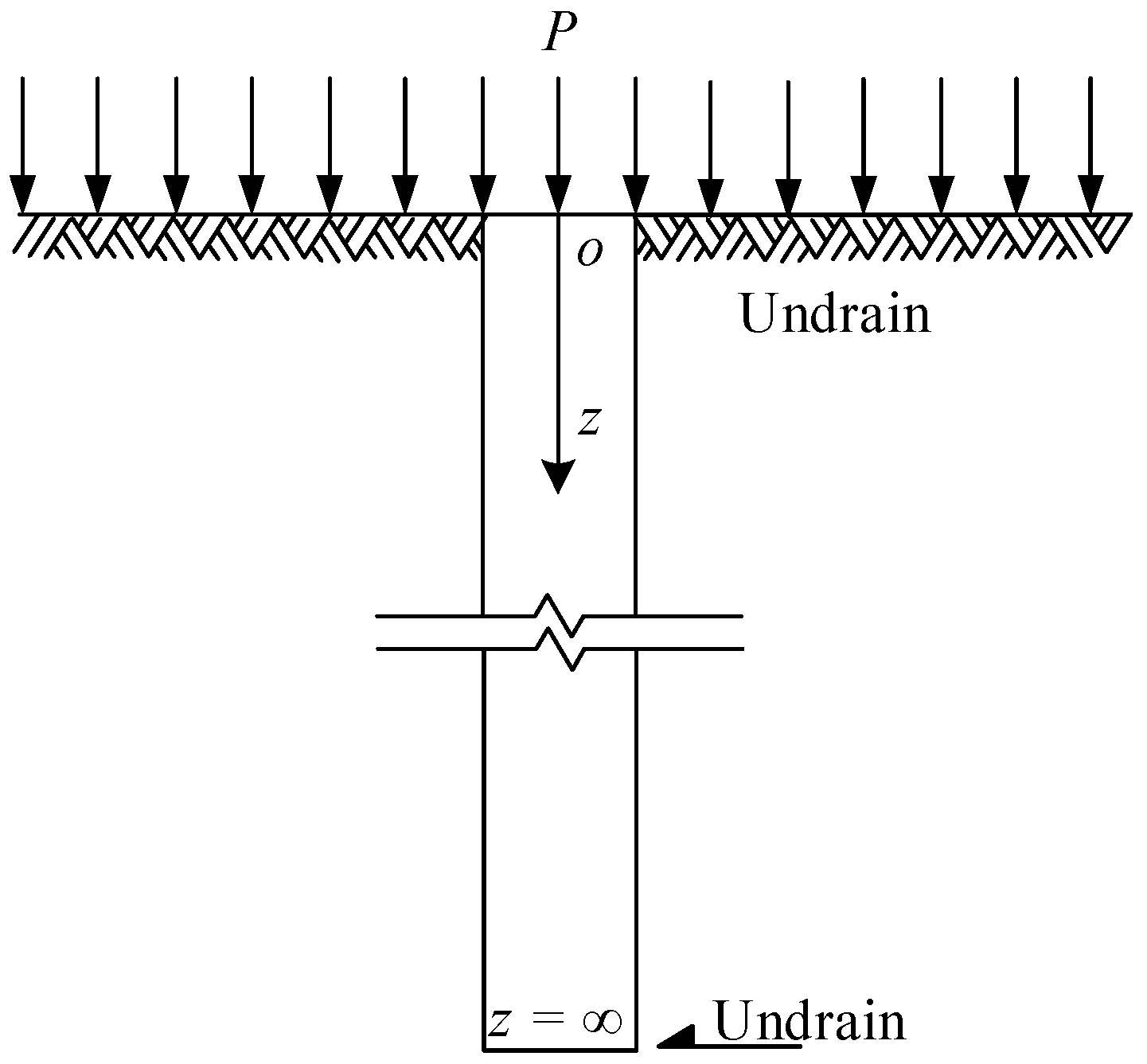
To evaluate the effect of pore tortuosity on the wave propagation in saturated soil, this study analyzes the one-dimensional undrained dynamic response of soil subjected to a step load of
P =
p0 on the top surface, as shown in
Figure 1. The soil layer is assumed to be of infinite depth in order to avoid the interference of wave reflections from the bottom boundary [
9]. The origin of the coordinate is located at the top surface of the soil layer, with the positive
z-axis directed downward. The initial conditions are
pex(
t) = 0,
σʹ(
t) = 0,
v(t) = 0, and
w(
t) = 0 at
t = 0. Under undrained conditions, the excess pore water pressure at the top surface induced by the step load is given by
p0. The derivation of the solutions for the excess pore water pressure and the velocities of the solid and liquid phases is detailed below.
Differentiating Equations (7) and (10) with respect to the vertical coordinate
z yields
Substituting Equation (9) into Equation (8) yields
By substituting Equations (9) and (14) into Equations (12) and (13), the governing equations can be reduced to the equations expressed in terms of incremental effective stress and excess pore pressure as
where
Equation (16) can be rewritten as
Substituting Equation (18) into Equation (15) results in a fourth-order partial differential equation
which is only governed by the excess pore water pressure, where
The general solution to Equation (19) takes the form
where
E1,
E2,
F1 and
F2 are integration constants to be determined by the boundary conditions. The coefficients α
1 and α
2 are given by
As the soil layer extends to an infinite depth, the solution must remain bounded as
z approaches infinity. This condition requires
E2 =
F2 = 0. Thus, Equation (21) reduces to
At the surface of the soil layer (
z = 0), the excess pore pressure is prescribed as the applied step load
p0, which in the Laplace domain takes the form
Substituting Equation (24) into Equation (23) yields
Under undrained conditions, the incremental effective stress at
z = 0 is
Substituting Equation (26) into Equation (16) yields
Inserting Equation (23) into the boundary condition Equation (27) results in
Solving Equations (25) and (28) simultaneously yields
The solution for the excess pore pressure in the Laplace domain is obtained by substituting Equation (29) into Equation (23). Furthermore, the solution for the incremental effective stress in the Laplace domain is obtained from Equations (18) and (23), as given by
Equation (7) can be rewritten as
Equations (10) and (31) can be written in matrix form as
where
Applying Cramer’s rule to Equation (32) yields
the solutions for the pore water and soil particles velocities in the Laplace domain, respectively, where
The inverse Laplace transforms of Equations (23) and (34) do not admit closed-form solutions in the time domain. Carter et al. [
11] neglected pore tortuosity in their analysis of one-dimensional linear elastic wave propagation, and employed Talbot’s [
23] numerical inverse Laplace transform to develop a computational program that yielded stable and convergent results. Following their approach and using an improved computational program, the numerical inverse Laplace transform is applied to Equations (23) and (34) to obtain the solutions in time domain for the excess pore pressure and the velocities of pore water and soil particles at arbitrary time and depth. In this study, a time step interval of 1 × 10
−6 s is used for performing calculations.
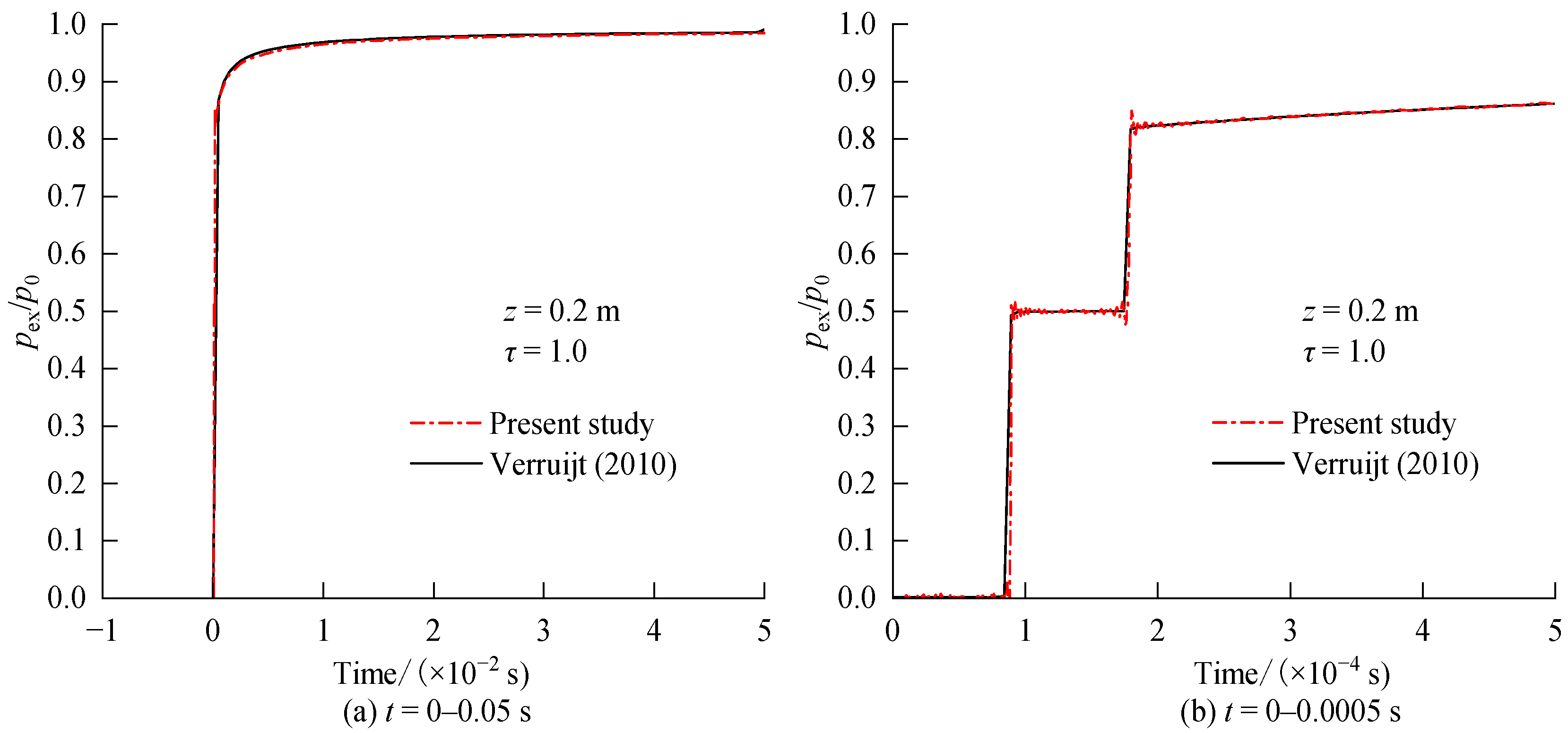
Verruijt [
10] developed an analytical solution to the wave propagation in a semi-infinite soil layer using the Fourier series technique. He analyzed the pore pressure response to a square-pulse loading with a period of 0.1 s in the absence of the pore tortuosity effect, i.e.,
τ = 1.0. For comparison purposes, the calculation parameters presented in Table 5.1 of Verruijt [
10] are adopted.
Figure 2 shows the calculated results obtained from the solution proposed in the present study and the solution developed by Verruijt [
10]. It can be seen that good agreement is obtained.
4. Distribution of Excess Pore Pressure and Propagation of Compressional Waves
Most of the soil parameters used in this analysis are consistent with those adopted by Carter et al. [
11]. The gravitational acceleration (
g) was assumed to be 10.0 m/s
2 as usually used in the soil mechanics community. Carter et al. [
11] assumed the compressibility of the soil skeleton
mv to be equal to the storativity of the pore space
Sp (Equation (6)). This assumption implied that the soil deformation only depends on the compression of pore water and soil particles, while the deformation associated with rearrangement of the soil skeleton is neglected. In this paper, the compressibility of the soil skeleton
mv is taken as a value greater than
Sp to account for the deformation of the soil skeleton itself caused by structural adjustment. The porosity (
n), hydraulic conductivity (
k) and volume compressibility (
mv) parameters are typical values for saturated coarse sand [
24,
25]. As mentioned above, Carter et al. [
11] did not account for the effect of pore tortuosity. In this study, the tortuosity factor
τ is taken as 1.0, 1.2, 1.5, 1.8, and 2.0, which fall in the typical range of 1.0 to 2.0 for sand [
26,
27]. These factors are adopted to evaluate the effect of pore tortuosity on the spatiotemporal distributions of excess pore water pressure, pore water velocity and soil particle velocity in saturated soil, as well as the propagation characteristics of compressional waves. The parameters used in computations are listed in
Table 1. Specially, the second term in Equation (1) becomes zero when
τ = 1.0, which indicates the effect of pore tortuosity is not considered.
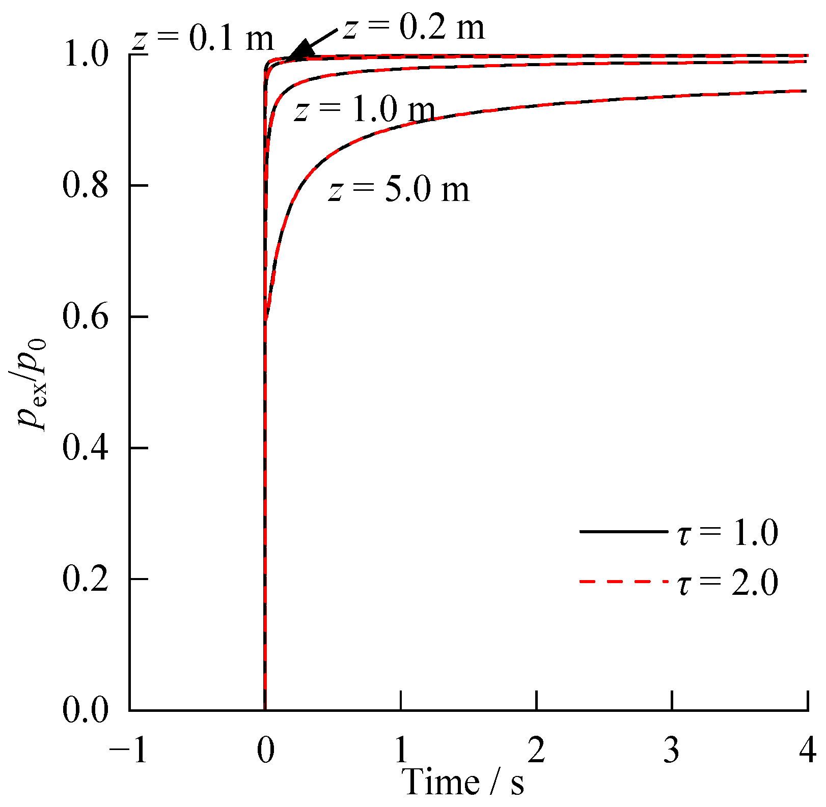
Figure 3 illustrates the temporal evolution of the normalized excess pore water pressure (
pex/
p0) at depths
z = 0.1, 0.2, 1.0, and 5.0 m, showing how excess pore water pressure propagates through the soil after the step load is applied. Obviously, the closer to the surface of the soil layer where the step load is applied, the faster the excess pore water pressure rises. In the shallow layer (
z ≤ 1 m), the excess pore water pressure rises rapidly to nearly the applied load value within an extremely short period (less than 1 s) and then remains a constant. In contrast, at greater depths, the excess pore water pressure requires considerably longer time to reach the same value. This behavior illustrates the hysteresis in the pore pressure response as the distance from the loading surface increases. Under undrained conditions, the excess pore water pressure eventually approaches the magnitude of the applied load, which is consistent with the pore pressure coefficient
B for the saturated soil closing to 1.0 [
21].
Figure 3 also shows that the calculated excess pore pressure for
τ = 1 and
τ = 2 at the same depth are nearly identical. However, it does not imply that pore tortuosity has no influence on the response of excess pore pressure, because the wave velocities in saturated soils are typically on the order of kilometers per second, and the transient response within depths of only a few tens of meters is difficult to capture on the time scale of seconds.
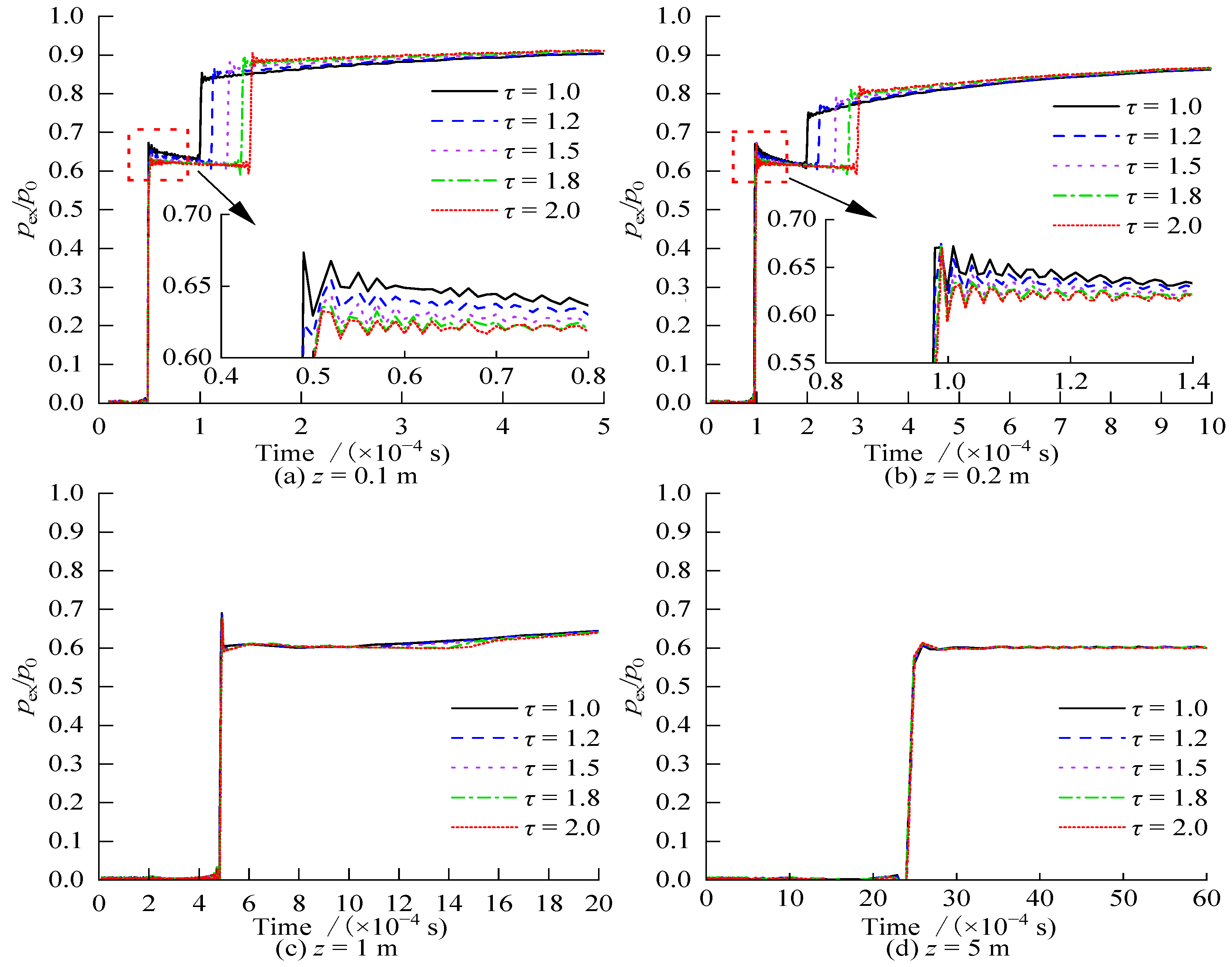
Figure 4 presents time histories of the normalized excess pore pressure dynamic response at various depths within the first few milliseconds after the application of a step load. The high-frequency oscillations observed in the curves are inherent feature of the numerical inverse Laplace transform algorithm, rather than a physical phenomenon. Notably, the scales of time-axis differ in each sub-figure, clearly illustrating the differences among the dynamic response curves.
As shown in
Figure 4, the build-up of excess pore pressure occurs in two distinct stages. In the first stage, the excess pore pressure at all depths rapidly rises to approximately 0.6–0.7 times the applied load
p0, which is induced by the arrival of the fast compressional wave. In the second stage, the excess pore pressure rises again at the arrival of the slow compressional wave. However, the magnitude of this increase diminishes rapidly with depth. Between these two stages, a slight drop in excess pore pressure is observed, which is primarily caused by the deformation of soil skeleton. In other words, if the compressibility of the soil skeleton is ignored (i.e.,
mv =
Sp as assumed by Carter et al. [
11]), the excess pore pressure would remain unaltered between these two stages. After the arrival of the slow compressional wave, the excess pore pressure continues to increase until it eventually approaches the applied load
p0 (as illustrated in
Figure 3). Moreover, the greater the depth, the longer it takes for the excess pore pressure to reach its steady value, namely, the hysteresis in the pore pressure response becomes more pronounced with depth.
During the first stage, the magnitude of the excess pore water pressure generated by the fast compressional wave is virtually independent of pore tortuosity, indicating that tortuosity has minor effect on the amplitude of the fast compressional wave. Moreover, the amplitude of excess pore pressure induced by the fast compressional wave shows no appreciable decrease with depth, confirming that the fast compressional wave propagates with minimal energy dissipation and thus behaves as the primary elastic wave. The magnitude of the excess pore pressure induced by the fast compressional wave is mainly governed by the compressibility of soil
mv and the storativity of pore space
Sp [
10].
In contrast, pore tortuosity exerts a significant influence on the arrival time and amplitude of the slow compressional wave. A larger tortuosity factor results in both a delayed arrival and a greater amplitude of this wave. As shown in
Figure 4a, at a depth of
z = 0.1 m, the increment of excess pore pressure induced by the slow compressional wave ranges between 0.2
p0 and 0.3
p0. However, at
z = 5.0 m (
Figure 4d), the amplitude is reduced to an almost indistinguishable level. This severe attenuation with depth explains why the slow compressional wave can only be observable in the vicinity of the loaded boundary.
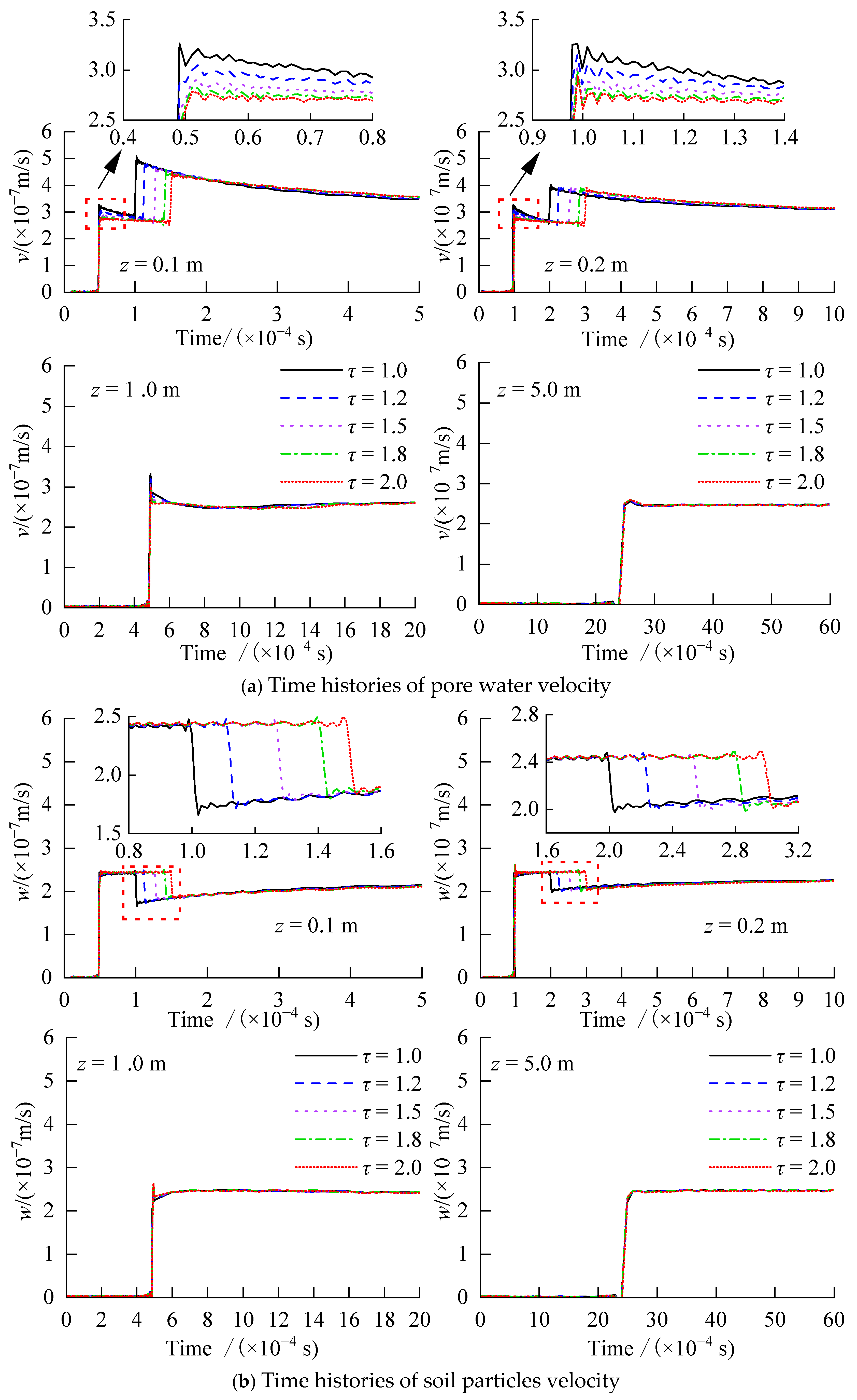
Figure 5a,b show the spatiotemporal distributions for the pore water velocity and soil particle velocity, respectively, both of which also display two stages as the excess pore water pressure response presented in
Figure 4.
During the first stage, the arrival of the fast compressional wave increases the velocities of both the pore water and soil particles, with the two phases moving in phase. This in-phase motion is the primary reason why the fast compressional wave experiences minimal energy attenuation along its propagation path and can travel considerable distances.
Figure 5 further shows that the velocity increment of pore water is greater than that of the soil particles, indicating the presence of relative motion between the two phases. This relative motion causes the subsequent decrease in pore water velocity and the concurrent drop in excess pore water pressure (
Figure 4) observed after the arrival of the fast compressional wave and before the arrival of the slow compressional wave. This demonstrates that the fast compressional wave does undergo energy dissipation, although it is not obvious. When the soil parameters satisfy the dynamic compatibility condition (
mv =
Sp as adopted by Carter et al. [
11]), namely, the volume change of soil equals the sum of the volume changes of the soil skeleton and pore water, the pore water velocity and the soil particle velocity induced by the fast compressional wave become identical. Under this condition, there is no inertial effects occur, and almost no energy is dissipated [
1]. Consequently, both the excess pore water pressure and pore water velocity would remain constant in the interval between the arrivals of the two waves [
11], which fails to reproduce the attenuated responses observed in
Figure 4 and
Figure 5a.
During the second stage, the pore water velocity increases and the soil particle velocity decreases upon the arrival of the slow compressional wave. This antiphase motion significantly amplifies the relative velocity between these two phases, thus, the pore water velocity declines again after the arrival of the slow compressional wave. Furthermore, the viscous drag force between the pore water and soil skeleton leads to rapid energy dissipation of the slow compressional wave, drastically limiting its transmission range. At a depth of z = 5.0 m, the influence of the slow compressional wave is almost undetectable.
As shown in
Figure 5, pore tortuosity exerts a certain influence on the pore water velocity induced by the fast compressional wave in the first stage, and almost has no effect on the soil particle velocity. In contrast, pore tortuosity has a pronounced effect on both the pore water and soil particle velocities induced by the slow compressional wave in the second stage, most notably on its arrival time or wave velocity.
The wave velocity can be obtained by dividing the depth of the calculation point by the arrival time of wave at the same point.
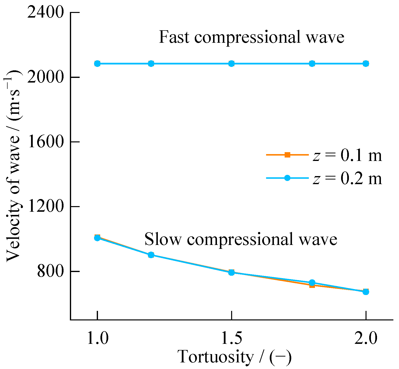
Figure 6 shows the variations of the fast and slow compressional wave velocities with the pore tortuosity at
z = 0.1 m. It can be observed that the velocity of the fast compressional wave remains constant at approximately 2083 m/s, which is unaffected by tortuosity factor. Moreover, the velocity of the fast compressional wave exhibits only limited reduction at greater depths because this wave displays minor energy dissipation. In contrast, the velocity of the slow compressional wave decreases notably with increasing tortuosity. This behavior is consistent with the inertial effects and energy dissipation caused by the antiphase motion increments of the pore water and soil particles induced by this wave. A larger tortuosity factor leads to a greater relative velocity between the pore water and soil particles, resulting in strong inertial effects, more rapid energy attenuation, and a faster decay of wave velocity.
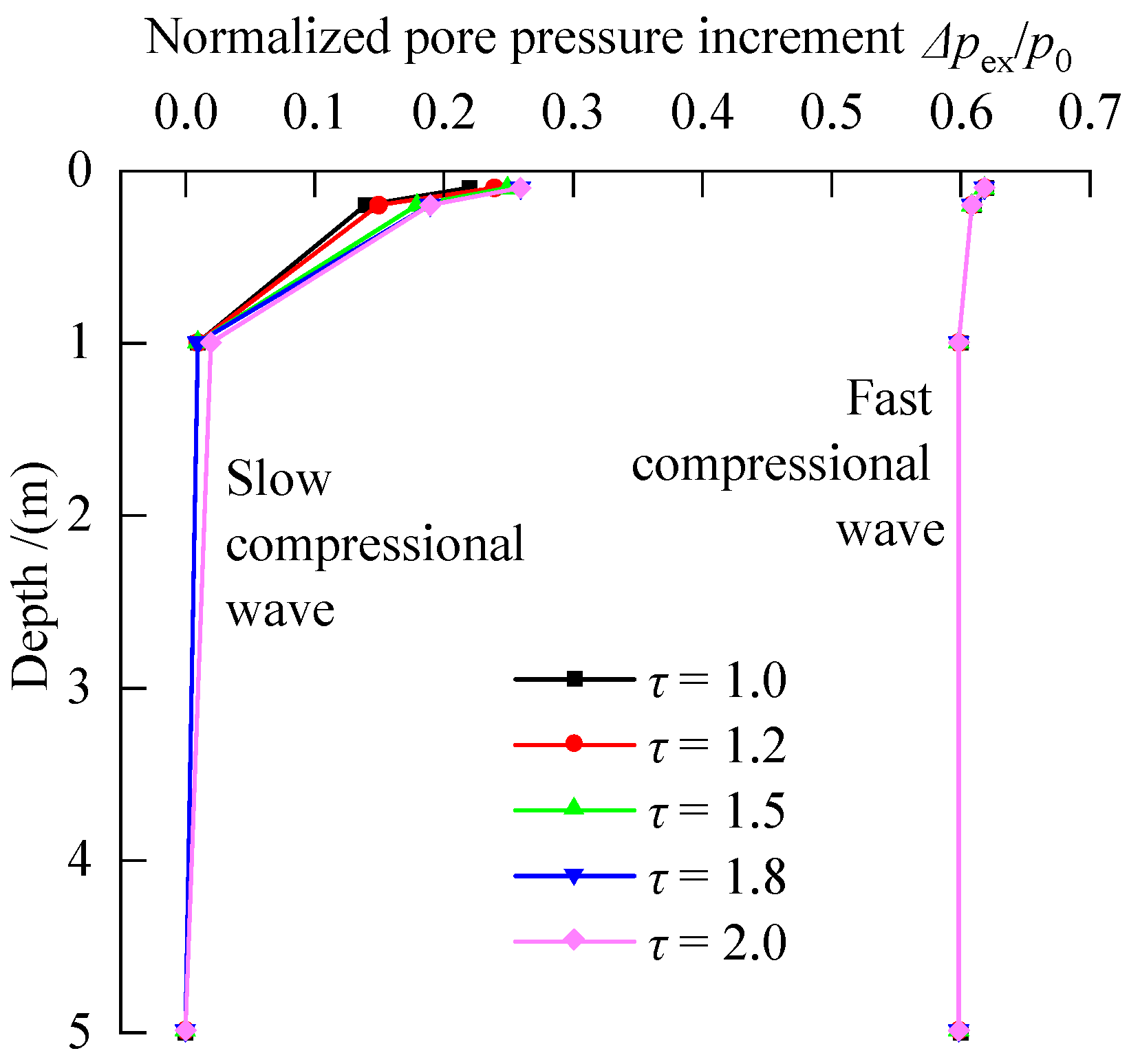
Figure 7 illustrates the variation of the excess pore water pressure amplitudes with depths induced by the fast and slow compressional waves. The amplitude of the fast compressional wave exhibits only mild attenuation with depth. In contrast, the amplitude of the slow compressional wave attenuates drastically and is sensitive to pore tortuosity. The amplitude of the excess pore pressure induced by the slow compressional wave decreases with increasing depths. This strong attenuation arises from energy dissipation caused by the viscous drag force. A greater depth implies more work done by this drag force, and greater energy loss. In essence, the propagation of slow compressional wave is a diffusive dissipative process characterized by low propagation velocity and strong attenuation. It can be regarded as analogous to a thermal conduction phenomenon with high energy loss under low-frequency conditions [
4]. These two characteristics result in the decrease in the wave amplitude with depths shown in
Figure 7. Therefore, the influence of slow compressional wave could be observed near the loading surface. Conversely, at greater depths, the energy of the slow compressional wave is dissipated through viscous drag force and seepage diffusion. This result indicates that in the dynamics analysis of geotechnical engineering problems, it is necessary to account for the tortuosity effect especially for the soils in close proximity to the soil–structure interface.
In the dynamic response of saturated soil, the propagation of the slow compressional wave is controlled primarily by viscous damping and inertial coupling between pore water and the soil skeleton. As tortuosity factor increases, the propagation velocity of the slow compressional wave decreases substantially, but the amplitude of the excess pore water pressure shows a slight increase. This phenomenon can be attributed to the inertial effect. The added mass force between the pore water and the soil skeleton hinders the movement of pore water and prevents efficient energy transfer to greater depths. This mechanism leads to localized energy retention and pressure concentration along the propagation path. This manifests as a slightly higher amplitude of excess pore pressure despite the reduced wave velocity. Furthermore, the distinction between the slow and fast compressional waves lies in the antiphase relative motion between the pore water and soil particles in the former. Therefore, the movement of pore water is affected by drag force, which in turn increases the gradient of the excess pore water pressure and elevates the peak response.
The main assumptions made to the model constructed in this study include one-dimensional wave propagation, small strain, undrained conditions, semi-infinite depth, linear elastic soil, constant permeability, and step loading. The proposed solution may be used for evaluating the build-up of pore pressure and ultimately analyzing the subsequent soil consolidation and foundation settlement. The main limitations of the model are the linear elasticity and constant permeability assumptions. By using an advanced numerical method, the model may be extended to allow for nonlinear soil properties and time-dependent loading.