Article

Point Cloud-Based Weld Seam Recognition and Localization for Robotic Welding

Key Laboratory of Light Field Manipulation and System Integration Applications in Fujian Province, College of Physics and Information Engineering, Minnan Normal University, Zhangzhou 363000, China
*
Author to whom correspondence should be addressed.
Appl. Sci. 2026, 16(17), 8879; https://doi.org/10.3390/app16178879
Submission received: 31 July 2026 / Revised: 3 September 2026 / Accepted: 4 September 2026 / Published: 7 September 2026

Abstract

The identification and spatial positioning of welds are key links in welding process matching and automatic welding path planning. Therefore, achieving automatic recognition and spatial positioning of weld point cloud features under online scanning imaging conditions is of great significance for the promotion and application of teaching free automatic welding technology. This article is based on a point cloud neural network model and conducts in-depth research on the recognition and spatial positioning algorithm of weld point cloud features. Specifically, the PointNet++ network, which is a point cloud neural network model, is first used to perform feature recognition on the three-dimensional point cloud of the welded parts obtained by laser line scanning. PointNet++ can distinguish different types of welded joints based on point cloud features and further perform preliminary rough positioning of the spatial position of the weld seam. After retaining the coarse positioning point cloud containing weld seam features, different algorithms are used to accurately locate the spatial position of the weld seam based on different weld seam features. The experimental results show that based on the PointNet++model for rough positioning, the weld length error does not exceed 0.3 mm, and the recognition accuracy and efficiency are much higher than traditional algorithms. The research results of this article can provide important references for the further intelligent development of automatic welding robots.

1. Introduction

In industrial production, welding technology serves as a critical process for permanent joining of metallic structures and is widely adopted in numerous industries including shipbuilding, automobile manufacturing, aerospace, pressure vessel fabrication and construction machinery [1,2]. Welding not only fulfills the high-strength joining of structural components but also plays a vital role in the machining of non-structural parts, exerting a direct influence on product performance and manufacturing efficiency [3]. Driven by the progressive implementation of intelligent manufacturing and Industry 4.0, welding technology achieves persistent upgrades in automation and intelligentization, with automatic welding robots trending from conventional teach-playback systems to teach-less counterparts [4]. Welding robots are integrated with 3D vision sensors to reconstruct three-dimensional models of workpieces, enabling precise perception of the geometric shape, dimension and spatial position of welding regions [5,6]. After completing hand–eye calibration between the 3D vision sensors and manipulators and combining robot motion control and path planning algorithms, these systems can realize high-precision automatic welding [7,8]. However, current teach-less welding systems still confront multiple challenges [9,10,11]. First, the accuracy of weld seam recognition for complex workpieces (e.g., those combining butt, corner, T-, and lap joints) remains unsatisfactory, triggering false detections and missing detections. Second, massive point cloud data imposes heavy computational load and obvious response latency on the system, which fails to satisfy strict real-time requirements. Third, limited adaptability of algorithms restricts their application under variable working conditions. In the broader domain of industrial intelligent manufacturing, transfer learning has proven highly effective in tackling such challenges. For instance, Siddique et al. [12] proposed a multistage transfer learning framework for rotating machinery fault diagnosis, which utilizes intermediate RPM domains to progressively align feature distributions, achieving high classification accuracy despite limited labeled data and varying operating speeds. This concept of progressive adaptation offers significant inspiration for addressing the variable conditions encountered in welding scenarios. Addressing these challenges requires further in-depth research on methods for weld seam recognition and localization from point cloud data.
In traditional weld seam recognition methods, plane fitting or intersection line extraction is commonly applied to point cloud data to determine the position of weld seams [13]. Point cloud data obtained by scanning workpieces with complex geometric structures and reflective surfaces contain substantial noise, which causes obvious deviations in fitting results and further degrades the accuracy of weld seam recognition [14]. Furthermore, the recognition algorithm suffers from poor real-time performance since point cloud data contains abundant redundant information, resulting in heavy computational loads and prolonged computation time for the system [15]. Driven by the rapid progress in deep learning over recent years, neural network-based methods for image feature recognition and localization have drawn widespread interest among researchers [6,16,17]. With the continuous maturity of artificial intelligence models and the continuous improvement of processor computing power, using neural networks to enhance the recognition accuracy and processing speed of weld seam features in large-scale point clouds has become one of the possible research paths [18,19,20]. Methods built on conventional neural networks such as convolutional neural networks (CNNs) are primarily applied to classify or localize weld seam morphology from two-dimensional images [21,22,23]. These models excel in feature extraction and classification accuracy yet fail to directly capture the 3D geometric features and precise spatial positions of weld seams due to the absence of depth information in 2D images. Modern welding robots obtain supplementary spatial depth information via stereo vision systems [24,25,26]. The point cloud data reflecting the workpiece’s geometry and spatial information acquired via stereo vision systems contains massive data volume, posing a challenge for teach-less systems to identify weld seams and their spatial locations. As a category of deep learning models specially designed for 3D point cloud processing, point cloud neural networks (PCNNs) enable point cloud classification, segmentation, detection, completion, registration and reconstruction [27,28,29,30]. In this paper, PCNNs are adopted to realize weld seam recognition and spatial localization from 3D point cloud data for improved accuracy and efficiency, facilitating autonomous teach-less welding.

2. Method—Weld Seam Recognition Based on PointNet++

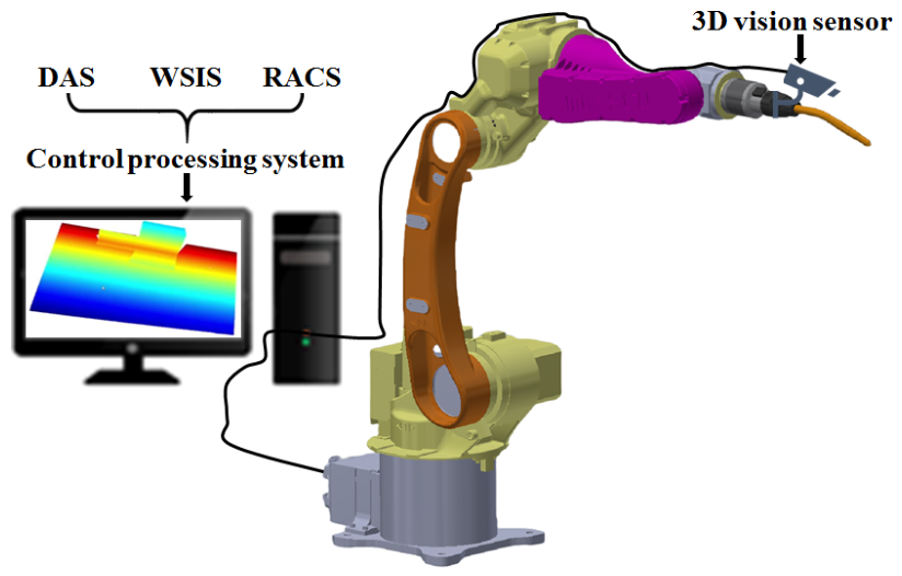
To eliminate invalid point cloud noise and improve the recognition efficiency and accuracy of the weld seam, the PointNet++ neural network is constructed in this study. With hierarchical processing and multi-scale feature extraction, PointNet++ can robustly process unevenly distributed point cloud data. In the teach-free automatic welding system shown in Figure 1, PointNet++ is arranged at the front end of the weld seam recognition system. It first identifies the overall workpiece and segments each constituent component of the workpiece based on the identification results. Afterwards, the weld seam recognition system realizes coarse weld seam localization using the segmented data and sends the localized weld seam point cloud to the weld seam fitting module to accomplish precise localization. Throughout the entire workflow from acquiring workpiece point clouds via 3D camera scanning to transmitting final weld seam spatial coordinates to the manipulator, PointNet++ plays a critical role. Its recognition efficiency and accuracy directly determine the performance of the weld seam detection subsystem and the overall teach-free automatic welding system. The following sections elaborate on the PointNet++-based weld seam recognition method from four aspects: experimental platform setup, data acquisition and dataset construction, deep learning model construction and optimization, as well as experimental verification.

2.1. Experimental Platform for Data Acquisition

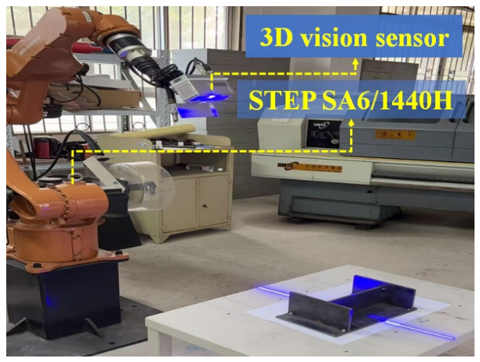
A hand–eye integrated automatic welding platform is constructed to acquire point cloud data of workpieces to be welded and verify the reliability of the PointNet++-based weld seam recognition system for automatic weld seam identification from point clouds. The platform consists of a welding robot (STEP SA6/1440H, Shanghai STEP Electric Corporation, Shanghai, China), a 3D laser line-scan camera (Vizum SVersion-HJ-RGBD-90, Beijing Vizum Technology, Beijing, China), a control processing system (Windows 10, intel Core i5-12400) and communication interfaces, as illustrated in Figure 2. The adopted welding robot is STEP SA6/1440H arc welding robot arm (communication servo drive) with a rated maximum payload of 6 kg and a maximum reach of 1475 mm, and is equipped with a 380 V power source. Benefiting from a hollow wrist design for internal cable routing to reduce mechanical interference, the robot achieves a repetitive positioning accuracy of ±0.05 mm, supports omnidirectional mounting, and delivers high-speed and stable operation. The 3D line-scan camera, Vizum SVersion-HJ-RGBD-90, features strong anti-interference performance when measuring highly reflective metallic surfaces and achieves depth measurement accuracy at the millimeter level. The camera is mounted on the end effector of the robot arm. During weld seam perception, it is driven by the robot arm to implement active scanning of workpieces for improved point cloud coverage and data integrity. After the camera captures 3D point cloud data characterizing the spatial position and geometric structure of workpieces, the data is sent to the control processing system through the communication interface. The control processing system converts the coordinates of all points within the point cloud into the base coordinate system of the welding robot using the transformation matrix from hand–eye calibration. The control processing system integrates three modules: point cloud acquisition control module, weld seam recognition module and robot arm control module. The point cloud acquisition module is in charge of raw data collection, filtering and format conversion. The weld seam recognition module classifies and segments point clouds and extracts weld seam regions relying on the deep learning network. The robot arm control module converts the identified weld seam into robot-executable welding trajectories and drives the welding torch to move along the planned paths.
The robotic welding system is equipped with welding capability. However, since this study focuses on kinematic validation, the welding source was not activated; therefore, electrical parameters were not recorded. For reference, the recommended settings for the welding wire are listed in Table 1.

2.2. Point Cloud Data Acquisition and Dataset Construction

Deep learning algorithms are data-driven and require abundant data for model training and optimization, which is also true for point cloud neural networks. Prior to the application of PointNet++ for weld seam recognition and rough positioning, substantial point cloud data of various workpieces is collected to construct a dataset for the training and optimization of the PointNet++ model. The more abundant and diverse the point cloud data are, the higher the accuracy and generalization performance of PointNet++ become. Therefore, the point cloud dataset should not only meet the training requirements in quantity but also possess sufficient diversity in terms of welded joint types, workpiece postures, point cloud density and noise characteristics. As shown in Figure 3, various workpieces are placed on the workbench in different postures according to practical industrial welding scenarios. The camera mounted on the welding robot arm scans these workpieces to acquire their point cloud data.
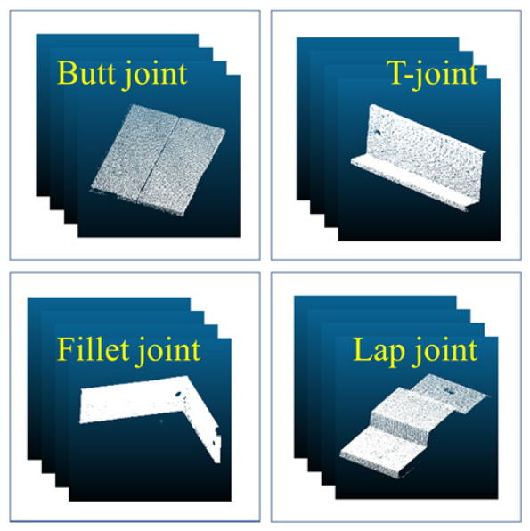
In this work, we collected 20 types of welded workpieces, including butt joints, corner joints, T-joints, and lap joints, and placed them on the workbench of the point cloud acquisition platform. A 3D line-scan camera was then used to capture point cloud data for each type of workpiece under multiple distances and viewing angles. To ensure complete geometric coverage and minimize collection bias, we acquired 20 scans per workpiece, with a point spacing of 0.2 mm. Similar to most data-driven deep learning network models, the richness of point cloud data directly affects its ability to represent the spatial structural information of welded joints. The larger the amount of data is, the better the optimization effect of the PointNet++ network is, thereby improving its robustness to different solder joint shapes. After completing point cloud imaging of various types of welded components, the point cloud data is divided into categories such as butt joints, corner joints, lap joints, and T-joints based on the characteristics of the weld seam, and a weld seam dataset is constructed, as shown in Figure 4.
For the convenience of network training, the weld seam area was further distinguished from the background base material in the classification dataset, and a semantic label dataset was constructed for training. The point clouds were manually annotated by using CloudCompare (v2.10), where each point was assigned to its corresponding category. The annotation results are stored in TXT file format, and each line records the three-dimensional coordinates of the points and their corresponding category labels. To ensure the quality of labeling and consistency of classification, this study developed a unified category coding rule for different types of welded joints, and the specific labeling categories are shown in Table 2.
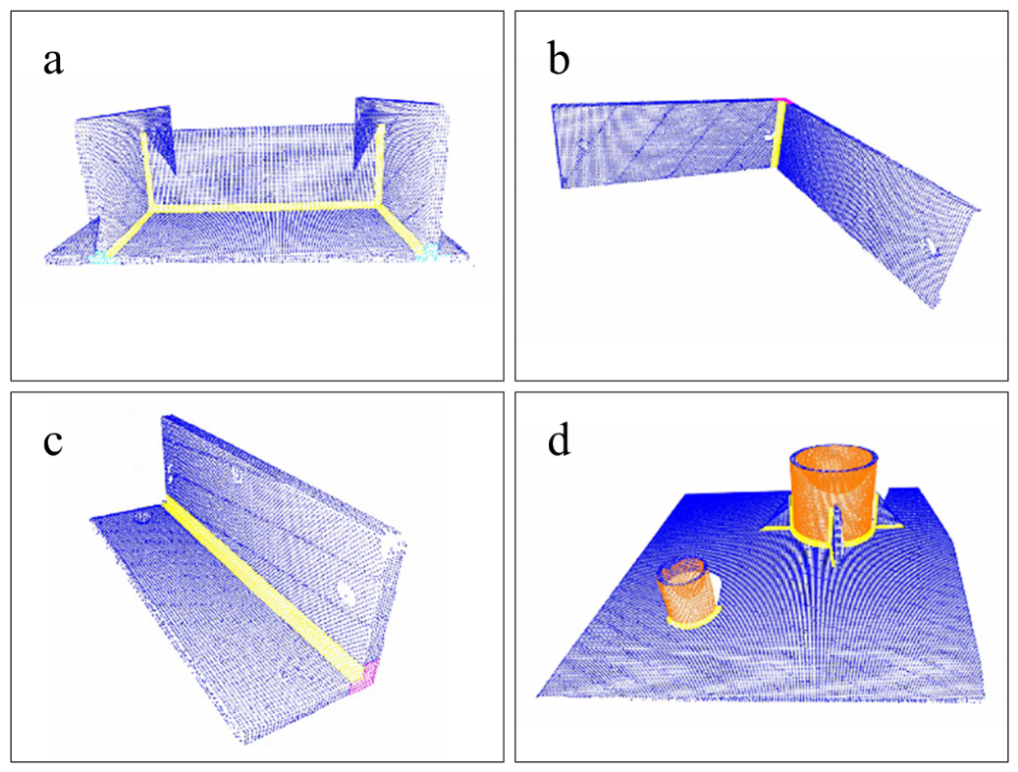
Figure 5 illustrates the annotated point clouds, where different labels are displayed in distinct colors. Regional refined annotation is adopted to reduce noise and point cloud data volume while retaining the geometric features of weld seams. Specifically, only weld seams and their nearby small areas are elaborately annotated, and large irrelevant point cloud regions are simply labeled as the workpiece body. This annotation strategy helps the model focus on weld regions and avoid interference from irrelevant workpiece structures during learning, thus improving the recognition accuracy. After data annotation, the data is split into training set, validation set and test set in the ratio of 70%, 20% and 10% for training and testing purposes.

2.3. Construction and Optimization of PointNet++

In the application of teach-less automatic welding, the weld recognition system is required to not only identify weld seams but also acquire their spatial positions. Compared with 2D images, 3D point cloud data contains both geometric features and 3D spatial coordinates of objects, so it is widely applied in automatic welding systems. However, point cloud data is characterized by disorder, irregularity, sparsity and non-uniform density. This makes traditional convolutional neural networks based on regular grid structures difficult to directly identify and locate weld seams precisely from point clouds. As an improved version of PointNet, PointNet++ introduces a hierarchical feature learning mechanism to recursively extract local and global geometric features at multiple scales. Its core idea is to construct local neighborhoods via Set Abstraction blocks and aggregate features using symmetric functions such as max pooling, which ensures the permutation invariance of the model to input point clouds. The entire model adopts a hierarchical structure of sampling, grouping, local feature extraction and aggregation to progressively learn the geometric hierarchical information of point clouds. PointNet++ achieves excellent performance on point clouds with uneven density and can effectively handle the complex and varied geometric shapes of industrial welding workpieces. Accordingly, this study employs PointNet++ to identify weld seams from point clouds for weld detection and coarse localization.
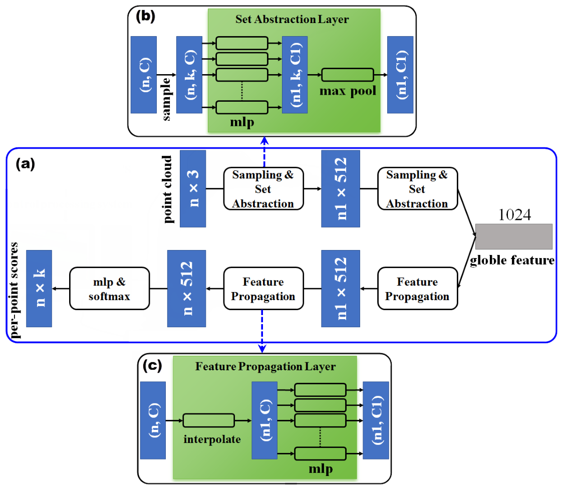
In order to effectively extract the point cloud features of the weld seam and complete the spatial localization of the weld seam, this paper constructs a PointNet++network model with the feature extraction module (Figure 6b) and the feature transfer module (Figure 6c) as the main components. The feature extraction module consists of four Set Abstraction (SA) layers, each of which includes three steps: Sampling, Grouping, and PointNet feature extraction (Multilayer Perceptron (MLP)+Pooling). The first two layers use smaller radii for local neighborhood search to capture small morphological differences on the weld surface, such as weld protrusions, weld toe transitions, and other local geometric features. The last two layers use larger sampling radii to aggregate global features and extract the overall geometric structure of welding types, such as butt straight line features, corner right angle features, or T-shaped intersection features. The Feature Propagation module consists of four Feature Propagation (FP) layers, mainly used to gradually restore high-level abstract features to the original point level resolution and achieve point cloud instance segmentation. Each FP layer fuses multi-scale features through interpolation and skip connections, and then refines them through MLP to ultimately output the classification probability of each point. This strategy of expanding the receptive field layer by layer enables the model to simultaneously learn local details and overall topology, improving the model’s ability to express complex weld geometry and differentiate between different types of welded joints, providing good point cloud features for segmenting point clouds.
Specifically, each Set Abstraction layer performs a spherical domain query centered at the sampling point of the current layer. Neighborhood points falling within the predefined radius are grouped into a local point set, and the coordinates and features of the points in this set are aggregated by a multi-layer perceptron and max pooling to produce the local feature vector of the sampling point. The Feature Propagation layer performs hierarchical interpolation upsampling from deep to shallow layers. It utilizes inverse distance weighting to interpolate features from the downsampled deep reference points to the points of the previous layer. Through skip connections, the interpolated features are concatenated and fused with the corresponding encoded features from the Set Abstraction layer. The fused features are then refined by a multi-layer perceptron (MLP), gradually restoring the point cloud to its original resolution. The ball query radius is typically determined based on the point density of the scanning data and the characteristic scale of the weld seam. Specifically, the shallow-layer ball query radius is set to one to two times the width of the weld seam, while the deep-layer radius is set to two to four times the shallow-layer radius. The specific training parameters are listed in Table 3.
Points of weld seams generally take up a very small proportion of the overall point cloud, resulting in severe positive and negative sample imbalance. If the standard cross-entropy loss function is adopted in PointNet++, the model will tend to classify the majority samples, which degrades the recognition performance of weld seams. To address this issue, this paper adopts the weighted cross-entropy loss function. Higher weights are assigned to weld seam points (positive samples), enabling the model to pay more attention to subtle features of weld seam regions during training. The loss function is defined as
L = i = 1 N w c i y i log p i
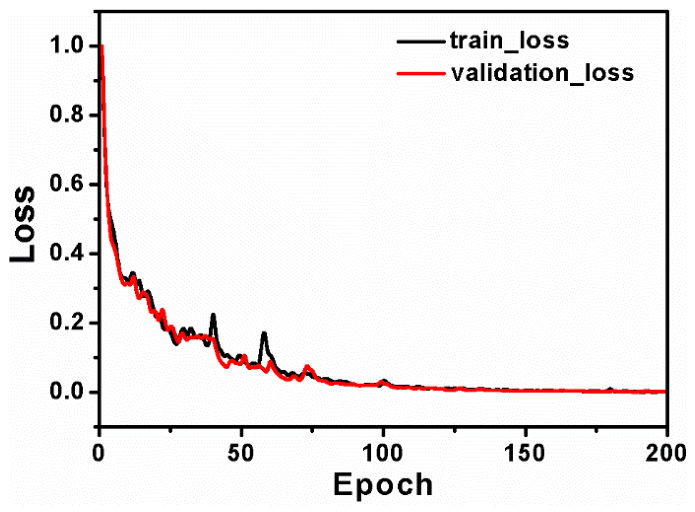
where w c i denotes the class weight, with a larger value assigned to the weld seam class; y i represents the ground-truth label; and p i is the probability predicted by the model. To mitigate the severe class imbalance (where the background points significantly outnumber the weld seam points), we assigned weights inversely proportional to their point frequencies. In our experiments, a weight ratio of 7:3 (weld seam to background) yielded optimal segmentation results. This weighting strategy effectively improves the recall rate of weld seam points and enables the model to achieve higher recognition accuracy for various types of joints. The loss curve of model training is shown in Figure 7. As the number of training epochs increases, the error gradually decreases, the prediction accuracy keeps rising, and the loss curve converges well. When the training reaches 100 epochs, the loss value approaches zero, indicating that the PointNet++-based weld seam recognition model has converged to its optimal state.

2.4. Weld Seam Recognition and Fitting Based on PointNet++

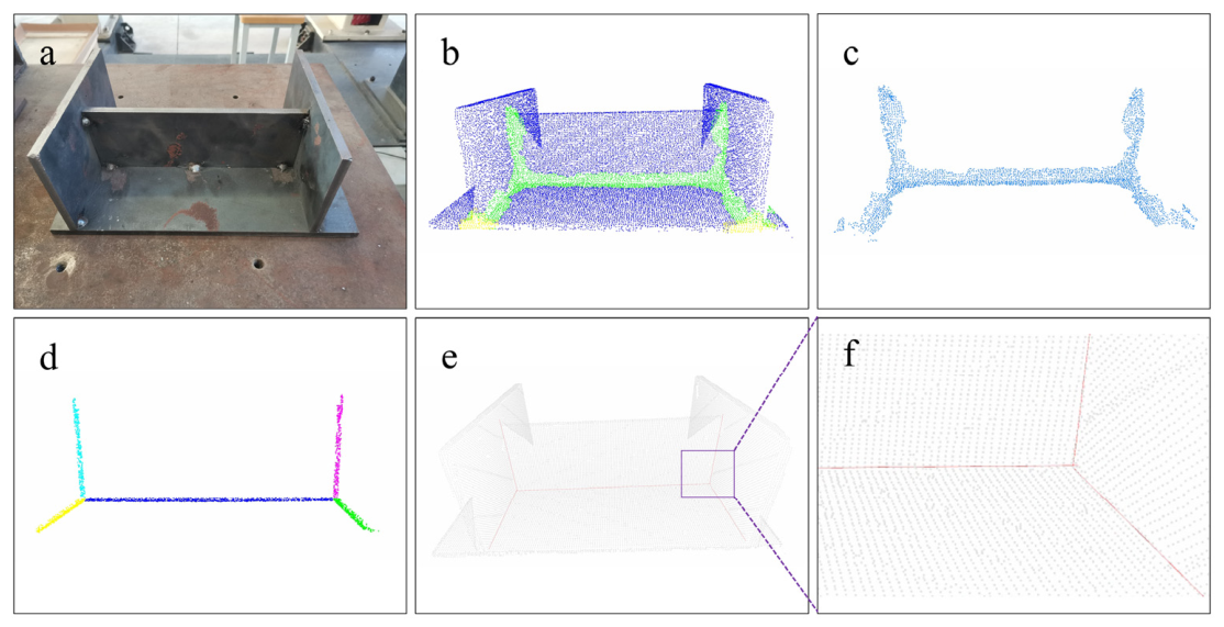
After the training of the PointNet++ model, I-shaped and cylindrical workpieces were selected as test samples to verify the model’s performance in weld seam recognition and rough localization. As shown in Figure 8a, the I-shaped workpiece is placed on the workbench for point cloud acquisition. The collected point cloud data is then imported into the PointNet++ model for recognition. The identified weld seam points are marked in green, as presented in Figure 8b. The labeling results show that PointNet++ can not only precisely locate weld seams, but also effectively distinguish adjacent points of weld seams from points on the workpiece body. After identifying the weld seam points, PointNet++ can also remove the points of the workpiece body, as illustrated in Figure 8c. Eliminating numerous irrelevant body points helps reduce computational cost for subsequent precise localization of weld seams and avoids interference from invalid point cloud data. Moreover, while realizing rough localization of weld seams, PointNet++ can also identify their joint types. The color marking of weld seams in Figure 8b indicates that the five welds are filet joints. The recognition of joint types can not only provide a basis for process matching in subsequent welding operations, but also serve as a reference for selecting algorithms for precise weld seam localization. The weld seams of filet joints, T-joints and lap joints can be geometrically represented as the intersection lines of two planes, or the intersection lines between a cylindrical surface and a plane. For example, the five weld seams on the I-shaped workpiece shown in Figure 8a are all typical filet joints. After the PointNet++ model performs rough localization and segmentation of weld seams in the point cloud, a point cloud subset of the weld seam region is obtained. On this basis, for filet joints, the RANSAC (Random Sample Consensus) algorithm is first applied for robust plane fitting. Inliers are filtered by setting a point-to-plane distance threshold to acquire the workpiece’s body planes on both sides of the weld seam, and the points near the intersection line of the two planes are extracted. Then, Principal Component Analysis (PCA) is applied to the point cloud of the intersection line to estimate its direction, and the initial direction parameter of the weld seam centerline is obtained. Finally, based on the PCA result, the least squares method is utilized for precise line fitting, and the analytical expression of the weld seam centerline is obtained. In this way, the precise spatial localization of the weld seam is accomplished, as shown in Figure 8d. As depicted in Figure 8e,f, the weld seam obtained via precise localization is rendered in the original workpiece point cloud and exhibits a high consistency with its actual position.
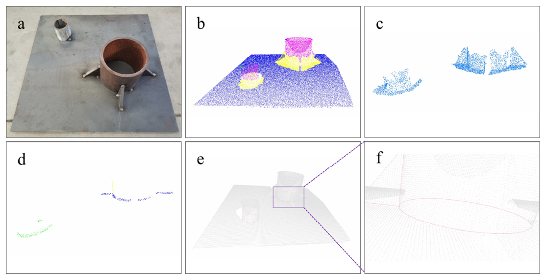
To further verify the performance of PointNet++ in weld seam recognition and rough localization, a more complex cylindrical workpiece (Figure 9a) was 3D scanned, and its point cloud data was fed into PointNet++. The weld seams identified from the point cloud and the weld seam point cloud obtained after removing the body points of the workpiece are shown in Figure 9b,c. Classified as a filet joint, its weld seam lies at the junction of cylindrical and planar surfaces and presents complex geometry. Its weld point cloud after rough localization is illustrated in Figure 9d. To achieve precise localization of such weld seams, cylindrical surface fitting is performed after PointNet++ completes weld seam type recognition and rough localization. An approximate fitting method based on the geometry of the cylindrical lateral surface is proposed. One point is selected from the segmented point cloud of the cylindrical lateral surface, and another point is randomly chosen to form a candidate direction vector. When this direction vector aligns with the axis of the cylinder, it passes through the maximum number of inliers. This method, which integrates random sampling and consensus evaluation, is used to estimate the cylinder axis direction. After the axis direction is acquired, a plane perpendicular to it is constructed. All the points of the cylindrical lateral surface are projected onto the plane, resulting in an approximately annular point set distribution. Afterwards, initial circle fitting is carried out on the projected point set via the RANSAC algorithm to remove outliers, followed by precise optimization of the circle center and radius using the least squares method. The center and radius correspond respectively to the axis position on the projection plane and the radius of the cylinder, enabling the fitting of the cylindrical lateral surface. After the fitting of the cylindrical lateral surface and the bottom plane is completed, the point cloud near their intersection line is extracted by setting distance constraint. For the point cloud of this intersection line, RANSAC and the least squares method are adopted again to fit the circle corresponding to the weld seam, so as to obtain its spatial analytical expression, as shown in Figure 9d. In summary, after PointNet++ completes weld seam recognition and coarse localization, complex circular weld seams can be precisely identified via the processing pipeline consisting of axis estimation, projection dimensionality reduction, circle fitting and intersection line extraction. As depicted in Figure 9e,f, the identified circular weld seam is rendered in the original workpiece point cloud and exhibits a high consistency with its actual position.
Finally, after the above point cloud processing and geometric fitting steps, the linear equation or spatial circle equation of the weld centerline and its corresponding spatial geometric parameters are obtained. For the convenience of subsequent welding robot path planning and welding trajectory generation, the fitted equation parameters will be uniformly organized and stored in TXT file format, providing a data foundation for subsequent welding trajectory calculation and robot motion control.

3. Discussion of Weld Seam Recognition

3.1. Recognition Accuracy and Time Consumption

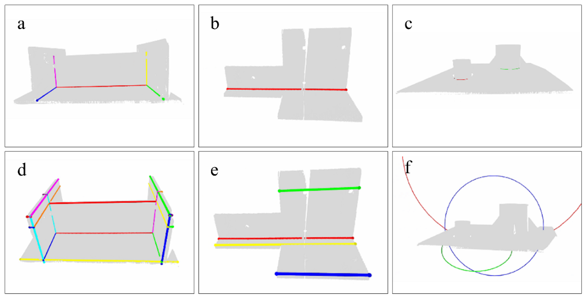
To make a comparison between the proposed weld seam recognition method integrating deep learning and geometric fitting and the traditional geometric fitting method, both are implemented for weld seam identification, and the corresponding results are illustrated in Figure 10. Recognition results of the hybrid method are given in Figure 10a–c. The results derived solely from geometric fitting without neural network processing are shown in Figure 10d–f. Among them, the identification of welds in Figure 10d,e employs a conventional geometric fitting approach, namely fitting the straight-line equation of the weld via RANSAC, PCA, and least squares to determine its spatial location, while Figure 10f, by contrast, fits the equation of a spatial circular arc using RANSAC and least squares to recognize the arc weld.
A respective comparison between Figure 10a and Figure 10d, Figure 10b and Figure 10e, as well as Figure 10c and Figure 10f reveals that for the same workpiece, direct geometric fitting on the raw point cloud without deep learning is vulnerable to noise points and complex structures, resulting in false recognition. After the PointNet++ model is introduced to identify and segment the point cloud of weld seam regions, irrelevant points are effectively removed and only the point set related to weld seams is retained. Accordingly, the accuracy of geometric fitting is improved. Furthermore, the segmentation by the PointNet++ model greatly reduces the data volume of the raw point cloud, which significantly improves the computational efficiency of the subsequent geometric fitting. For example, Figure 10a shows the geometric fitting result after the workpiece point cloud is segmented by the PointNet++ model, with the fitting process taking only 0.9106 s. In comparison, Figure 10d presents the result obtained by directly using the raw point cloud of the same workpiece for geometric fitting, which takes 2.5349 s, an increase of 178% in time consumption.

3.2. Error Analysis

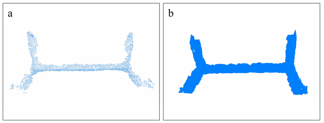
After weld seam recognition using the method combining deep learning and geometric fitting, the spatial positioning accuracy of the detected weld seams is quantitatively analyzed. It should be noted that during feature extraction, PointNet++ generally down-samples the raw point cloud via Farthest Point Sampling (FPS). Feature learning and category prediction are performed only on the sampled points. If geometric fitting of weld seams is performed solely on sampled points, insufficient points involved in the fitting process may introduce large errors and degrade the positioning accuracy of weld seams. To reduce error accumulation caused by sampling, the K-Nearest Neighbors (KNN) algorithm is introduced to propagate labels on the raw point cloud after segmentation by PointNet++.
Specifically, using the sampled points with completed category predictions as the reference point set, a point-by-point neighborhood search is performed on the unsampled points in the original point cloud. For any unsampled point, its three-dimensional coordinates serve as the query center to search for K neighboring points within a radius R in the classified sampled point set, and the number and proportion of points belonging to each category in this neighborhood are counted. Based on the category distribution in the neighborhood, the corresponding labels are propagated to the current unsampled point, thereby restoring the semantic segmentation results of the weld area from the sampled resolution back to the original point cloud resolution. Considering that there is usually significant category uncertainty at the boundary between the weld seam and the background, directly propagating the category to downsampled points with sparse neighborhoods can easily lead to the erroneous diffusion of weld labels into the background area. To mitigate the impact of such error propagation, this paper further introduces a threshold to determine the validity of neighborhoods. When the number of valid reference points found within the radius R of the query point is less than the preset threshold, the region is considered to lack sufficient category judgment basis (usually corresponding to weld edges or sparse point cloud areas) and is therefore excluded from the label recovery process. By employing the aforementioned neighborhood constraints and category voting strategy, the proposed method effectively suppresses misclassification in edge regions while restoring the original density of the point cloud. This yields a more complete and accurate weld point cloud, providing a high-quality data foundation for subsequent geometric fitting and spatial positioning. The comparison before and after label recovery is shown in Figure 11.
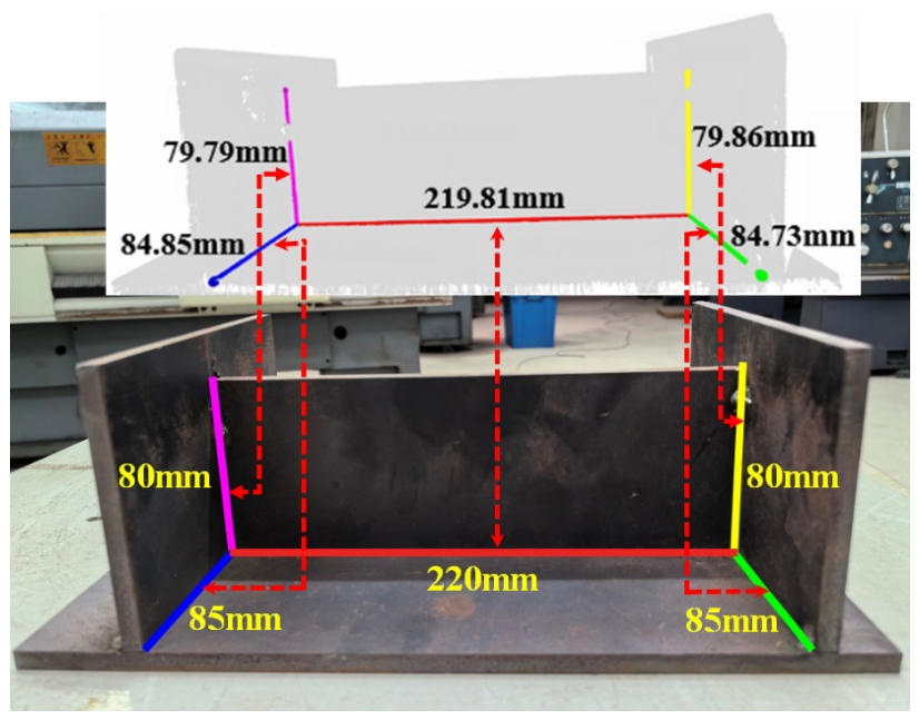
On this basis, the weld seam shown in Figure 12 was selected as the experimental object, and its geometric length and spatial positioning were statistically analyzed; the results are presented in Figure 12. As shown in Table 4, the proposed method achieves high-precision weld seam positioning across various welding structures, with a weld seam length error not exceeding 0.3 mm. Furthermore, compared to the baseline method that does not utilize the K-Nearest Neighbors (KNN) algorithm to recover point cloud density, the proposed method demonstrates a significant advantage in error control. In the automatic welding process of industrial robots, the accuracy of weld seam recognition and spatial positioning directly affects the planning of welding trajectory and the final welding quality. Especially for geometric parameters such as weld length and position, if there is a significant error in the recognition results, it may lead to the robot’s actual welding trajectory being smaller than the real weld, resulting in problems such as missed welding. Therefore, conducting error analysis on the identification results of weld seams and using the maximum error as one of the evaluation indicators is of great significance for determining whether the algorithm meets the actual industrial welding needs.
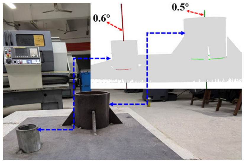
For the accuracy evaluation of cylindrical surface recognition, the angle between the cylinder axis and the normal vector of the reference plane is adopted as the error index. As shown in Figure 13, the black lines indicate the normal direction of the workpiece bottom surface, and the red and green lines represent the axes of the two cylindrical surfaces. The cylindrical surfaces of the actual workpiece are perpendicular to its bottom surface. Therefore, this index can effectively reflect the geometric deviation between the identified cylindrical surfaces and the real ones.
The cylindrical surface fitting method based on the geometry of the cylindrical lateral surface proposed in this paper is presented in Section 2.4. It achieves high-precision localization of the cylinder axis through prior estimation of the axial direction and constrained optimization. Compared with the traditional cylindrical surface fitting method based on global RANSAC, this approach avoids the vulnerability of global parameter search to noise, thus delivering higher stability and accuracy in cylinder axis estimation. As indicated by the cylindrical surface recognition errors in Figure 13, the angular deviations between the fitted cylinder axes and the normal direction of the corresponding reference plane are all within 1°, which is significantly better than that of the traditional global RANSAC fitting method. These results verify the effectiveness and accuracy advantages of the proposed method for cylindrical axis estimation, which ensures high-precision spatial positioning of complex curved weld seams. To verify the feasibility of PointNet++ combined with a geometric fitting algorithm, we employ the platform in Figure 3 to perform a teach-less welding demonstration on the workpiece in Figure 13 (see Video S1). The video demonstrates that the proposed method can accurately determine the weld’s spatial location for teach-less welding.

3.3. Limitations and Future Work

Although the proposed method demonstrates the capability of recognizing and localizing weld seams from three-dimensional point clouds and generating corresponding robot welding trajectories, the current experimental validation was conducted under simulated welding conditions. No actual arc welding or material deposition was performed in the present study. Therefore, the relationship between weld seam recognition accuracy, welding process parameters, and the quality of the resulting weld has not yet been experimentally investigated.
In future work, an actual robotic welding system incorporating a welding power source, welding wire feeding system, and process parameter control will be integrated with the proposed weld seam recognition framework. Experimental investigations will then be conducted to evaluate the influence of welding current, arc voltage, welding speed, and other process parameters on weld formation and quality. Quantitative measurements of the resulting weld geometry, including weld width, reinforcement height, and penetration characteristics, will also be performed. Furthermore, the relationship between the geometric accuracy of weld seam recognition and the final welding quality will be systematically analyzed.

4. Conclusions

This paper proposes a weld point cloud feature recognition and spatial positioning method based on PointNet++ to address the issues of insufficient accuracy in weld seam recognition, susceptibility to irrelevant point cloud interference in traditional geometric fitting, and low computational efficiency in the process of automatic welding without teaching. Firstly, a welding seam point cloud acquisition platform consisting of 3D vision sensors and a six degree of freedom industrial robot was established to collect 3D point cloud data of typical welding workpieces such as butt joints, corner joints, T-joints, and lap joints. The welding seam point cloud dataset was constructed through manual annotation. Secondly, PointNet++ is used to learn features and perform semantic segmentation on the point cloud of the welded workpiece, achieving automatic recognition and rough positioning of the weld area, effectively removing a large number of irrelevant point clouds, and reducing the computational complexity of subsequent geometric fitting. To address the issue of reduced point cloud density caused by sampling from the farthest point in the network, the K-Nearest Neighbors method is introduced to propagate the category information of the sampled points to the original point cloud, reducing error propagation in the edge region while restoring the point cloud density in the weld area. In the precise positioning stage, based on the geometric characteristics of different welded joints, algorithms such as RANSAC, PCA, least squares, and FPFH are used for geometric fitting to obtain the centerline or spatial curve of the weld seam. The experimental results show that the method proposed in this paper can effectively identify and spatially locate different types of welds, with weld length errors controlled within 0.3 mm. Compared with the method of directly fitting the complete point cloud geometrically, the method proposed in this paper effectively reduces the interference of irrelevant point clouds on the fitting process while ensuring the positioning accuracy, and improves the overall processing efficiency. The recognition process and results can be found in the attached animated video (Supplementary Materials). In summary, the “PointNet++ coarse positioning and geometric fitting fine positioning” method proposed in this article can fully leverage the advantages of deep learning and traditional geometric algorithms, providing an effective technical foundation for weld seam recognition, spatial positioning, and subsequent robot path planning in teaching free automatic welding. Although the current work does not involve arc ignition, the motion stability verified in this study lays the foundation for future closed-loop control integrating real-time current/voltage feedback.

Supplementary Materials

The following supporting information can be downloaded at: https://www.mdpi.com/article/10.3390/app16178879/s1.

Author Contributions

Neural network architecture construction, drafting the original manuscript, reviewing and editing the paper, X.-L.M.; experimental data acquisition and data cleaning, L.-H.N., H.-T.S., Z.-M.H. and Y.L.; reviewing and editing the manuscript, overall coordination to ensure that all necessary information and data are properly included, H.-C.L.; development and implementation of geometric fitting algorithms, J.Z. All authors have read and agreed to the published version of the manuscript.

Funding

This research received no external funding.

Data Availability Statement

The raw data supporting the conclusions of this article will be made available by the authors on request.

Conflicts of Interest

The authors declare no conflict of interest.

Abbreviations

The following abbreviations are used in this manuscript:
PCNNsPoint Cloud Neural Networks
RANSACRandom Sample Consensus
PCAPrincipal Component Analysis
MLPMultilayer Perceptron
KNNK-Nearest Neighbors

References

  1. Kah, P.; Latifi, H.; Suoranta, R.; Martikainen, J.; Pirinen, M. Usability of arc types in industrial welding. Int. J. Mech. Mater. Eng. 2014, 9, 15. [Google Scholar] [CrossRef] [Scilit]
  2. Ogbemhe, J.; Mpofu, K. Towards achieving a fully intelligent robotic arc welding: A review. Ind. Robot An. Int. J. 2015, 42, 475–484. [Google Scholar] [CrossRef] [Scilit]
  3. Erdős, G.; Kemény, Z.; Kovács, A.; Váncza, J. Planning of remote laser welding processes. Procedia CIRP 2013, 7, 222–227. [Google Scholar] [CrossRef] [Scilit]
  4. Vora, J.; Badheka, V.J. (Eds.) Advances in Welding Technologies for Process Development; CRC Press: Boca Raton, FL, USA, 2019. [Google Scholar]
  5. Xu, F.; Xu, Y.; Zhang, H.; Chen, S. Application of sensing technology in intelligent robotic arc welding: A review. J. Manuf. Process. 2022, 79, 854–880. [Google Scholar] [CrossRef] [Scilit]
  6. Fan, X.A.; Gao, X.; Liu, G.; Ma, N.; Zhang, Y. Research and prospect of welding monitoring technology based on machine vision. Int. J. Adv. Manuf. Technol. 2021, 115, 3365–3391. [Google Scholar] [CrossRef] [Scilit]
  7. Shi, Y.; Zhang, G.; Kong, M. Path planning of welding robot based on deep learning. Paladyn 2024, 15, 20240002. [Google Scholar] [CrossRef] [Scilit]
  8. Zhang, H.Y.; Lin, W.M.; Chen, A.X. Path planning for the mobile robot: A review. Symmetry 2018, 10, 450. [Google Scholar] [CrossRef] [Scilit]
  9. Ali, R.; El-Betar, A.; Magdy, M. A review on optimization of autonomous welding parameters for robotics applications. Int. J. Adv. Manuf. Technol. 2024, 134, 5065–5086. [Google Scholar] [CrossRef] [Scilit]
  10. Bu, H.; Cui, X.; Huang, B.; Peng, S.; Wan, J. Research review and future directions of key technologies for welding robots in the construction industry. Buildings 2024, 14, 2261. [Google Scholar] [CrossRef] [Scilit]
  11. Stavropoulos, P.; Sabatakakis, K. Quality assurance in resistance spot welding: State of practice, state of the art, and prospects. Metals 2024, 14, 185. [Google Scholar] [CrossRef] [Scilit]
  12. Siddique, M.F.; Zaman, W.; Khalid, M.; Hamdan, B.; Kim, J.-M. A multistage transfer learning framework for intelligent fault diagnosis of rotating machinery under variable operating conditions. Sci. Rep. 2026, 26, 47377. [Google Scholar] [CrossRef] [Scilit]
  13. Yang, L.; Liu, Y.; Peng, J.; Liang, Z. A novel system for off-line 3D seam extraction and path planning based on point cloud segmentation for arc welding robot. Robot. Comput.-Integr. Manuf. 2020, 64, 101929. [Google Scholar] [CrossRef] [Scilit]
  14. Wang, H.; Huang, Y.; Zhang, G.; Rong, Y. A novel method for dense point cloud reconstruction and weld seam detection for tubesheet welding robot. Opt. Laser Technol. 2023, 163, 109346. [Google Scholar] [CrossRef] [Scilit]
  15. Zhou, P.; Peng, R.; Xu, M.; Wu, V.; Navarro-Alarcon, D. Path planning with automatic seam extraction over point cloud models for robotic arc welding. IEEE Robot. Autom. Lett. 2021, 6, 5002–5009. [Google Scholar] [CrossRef] [Scilit]
  16. Zou, Y.; Chen, X.; Gong, G.; Li, J. A seam tracking system based on a laser vision sensor. Measurement 2018, 127, 489–500. [Google Scholar] [CrossRef] [Scilit]
  17. Li, Y.; Li, Y.F.; Wang, Q.L.; Xu, D.; Tan, M. Measurement and defect detection of the weld bead based on online vision inspection. IEEE Trans. Instrum. Meas. 2009, 59, 1841–1849. [Google Scholar] [CrossRef] [Scilit]
  18. Du, R.; Xu, Y.; Hou, Z.; Shu, J.; Chen, S. Strong noise image processing for vision-based seam tracking in robotic gas metal arc welding. Int. J. Adv. Manuf. Technol. 2019, 101, 2135–2149. [Google Scholar] [CrossRef] [Scilit]
  19. Lü, X.; Gu, D.; Wang, Y.; Qu, Y.; Qin, C.; Huang, F. Feature extraction of welding seam image based on laser vision. IEEE Sens. J. 2018, 18, 4715–4724. [Google Scholar] [CrossRef] [Scilit]
  20. Yang, L.; Wang, H.; Huo, B.; Li, F.; Liu, Y. An automatic welding defect location algorithm based on deep learning. NDT E Int. 2021, 120, 102435. [Google Scholar] [CrossRef] [Scilit]
  21. Li, J.; Li, B.; Dong, L.; Wang, X.; Tian, M. Weld seam identification and tracking of inspection robot based on deep learning network. Drones 2022, 6, 216. [Google Scholar] [CrossRef] [Scilit]
  22. Zhang, J.; Li, P.H.; Zhang, M.X.; Shen, K.H.; Xing, Y.Z. A review of algorithms for surface defect detection in welds based on machine learning. Expert Syst. Appl. 2025, 299, 130188. [Google Scholar] [CrossRef] [Scilit]
  23. Zhu, S.; Zhang, L.; Zhao, J.; Hu, X.; Luo, X. Research on steel structure weld seam recognition algorithm based on improved YOLOv5. Sci. Rep. 2025, 15, 34276. [Google Scholar] [CrossRef] [Scilit]
  24. Zou, Y.; Chen, T.; Chen, X.; Li, J. Robotic seam tracking system combining convolution filter and deep reinforcement learning. Mech. Syst. Signal Process. 2022, 165, 108372. [Google Scholar] [CrossRef] [Scilit]
  25. Wang, N.; Zhong, K.; Shi, X.; Zhang, X. A robust weld seam recognition method under heavy noise based on structured-light vision. Robot. Comput.-Integr. Manuf. 2020, 61, 101821. [Google Scholar] [CrossRef] [Scilit]
  26. Chen, S.; Liu, J.; Chen, B.; Suo, X. Universal fillet weld joint recognition and positioning for robot welding using structured light. Robot. Comput.-Integr. Manuf. 2022, 74, 102279. [Google Scholar] [CrossRef] [Scilit]
  27. Qi, C.R.; Su, H.; Mo, K.; Guibas, L.J. Pointnet: Deep learning on point sets for 3d classification and segmentation. In Proceedings of the IEEE Conference on Computer Vision and Pattern Recognition; IEEE: New York, NY, USA, 2017; pp. 652–660. [Google Scholar]
  28. Qi, C.R.; Yi, L.; Su, H.; Guibas, L.J. Pointnet++: Deep hierarchical feature learning on point sets in a metric space. In Proceedings of the 31st International Conference on Neural Information Processing Systems (NIPS’17), Long Beach, CA, USA, 4–9 December 2017. [Google Scholar]
  29. Wang, Y.; Sun, Y.; Liu, Z.; Sarma, S.E.; Bronstein, M.M.; Solomon, J.M. Dynamic graph cnn for learning on point clouds. ACM Trans. Graph. TOG 2019, 38, 146. [Google Scholar] [CrossRef] [Scilit]
  30. Thomas, H.; Qi, C.R.; Deschaud, J.E.; Marcotegui, B.; Goulette, F.; Guibas, L.J. Kpconv: Flexible and deformable convolution for point clouds. In Proceedings of the IEEE/CVF International Conference on Computer Vision, Seoul, Republic of Korea, 27 October–2 November 2019; pp. 6411–6420. [Google Scholar]
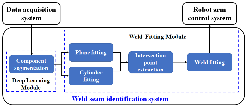
Figure 1. Block diagram of the teaching-free automatic welding control system.
Applsci 16 08879 g001
Figure 2. Experimental platform of the hand–eye integrated automatic welding system, DAS—Data Acquisition System, WSIS—Weld Seam Identification System, and RACS—Robot Arm Control System.
Applsci 16 08879 g002
Figure 3. Experimental setup for workpiece scanning and point cloud data acquisition using 3D vision sensor and robot arm.
Applsci 16 08879 g003
Figure 4. Schematic diagram of datasets constructed by classifying point cloud data according to weld joint types.
Applsci 16 08879 g004
Figure 5. Examples of annotated point clouds ((ad) represent four common welding workpieces. Blue: workpiece body; yellow: filet joint; orange: cylindrical surface; cyan and purple: T-joint).
Applsci 16 08879 g005
Figure 6. Schematic diagram of the PointNet++ network structure: (a) Main network architecture, (b) Set Abstraction layer module, and (c) Feature Propagation layer module.
Applsci 16 08879 g006
Figure 7. Loss curve of the weighted cross-entropy loss function.
Applsci 16 08879 g007
Figure 8. Recognition and spatial localization of weld seam for I-shaped workpiece. (a) Photo of the I-shaped workpiece; (b) recognition result of weld seam by PointNet++; (c) point cloud of weld seam after removing irrelevant points; (d) precisely localized weld seam by geometric fitting on weld seam point cloud; (e,f) weld seam recognition and spatial localization achieved by combining PointNet++ with geometric fitting algorithms.
Applsci 16 08879 g008
Figure 9. Recognition and spatial localization of weld seam for cylindrical workpiece. (a) Photo of the cylindrical workpiece; (b) recognition result of weld seam by PointNet++; (c) point cloud of weld seam after removing irrelevant points; (d) precisely localized weld seam by geometric fitting on weld seam point cloud; (e,f) weld seam recognition and spatial localization achieved by combining PointNet++ with geometric fitting algorithms.
Applsci 16 08879 g009
Figure 10. Comparison of weld seam recognition performance between the hybrid method and traditional geometric fitting method. (ac) Recognition results of the method combining deep learning and geometric fitting; (df) recognition results of the traditional geometric fitting method. The bold lines marked with different colors in the figure represent the identified weld seams.
Applsci 16 08879 g010
Figure 11. Comparison of weld seam point clouds before and after restoration via the K-Nearest Neighbors algorithm: (a) sparse weld seam point cloud identified by PointNet++; (b) complete weld seam point cloud recovered via the K-Nearest Neighbors algorithm.
Applsci 16 08879 g011
Figure 12. Comparison between actual dimensions and geometric dimensions of weld seams identified from point cloud for I-shaped workpiece.
Applsci 16 08879 g012
Figure 13. Recognition error results of arc weld seams obtained via quantitative analyses.
Applsci 16 08879 g013
Table 1. Common welding parameters.
Wire Feed Speed (m/min)Current (A)Voltage (V)
1.507515.8
1.557615.8
1.607815.9
1.658015.9
1.708216.0
1.758316.1
1.808516.1
1.507515.8
Table 2. Label encoding scheme for point clouds.
PartLabel
Workpiece body0
Butt joint1
Filet joint2
L-joint3
T-joint4
Lap joint5
Cylindrical surface6
Workbench7
Table 3. Neural network training parameter table.
TypeParameter
Sampling sizes at each Set Abstraction layer2048, 1024, 512, 128
Neighborhood radius (taking the first layer as an example)0.1, 0.2, 0.4
Number of neighbors (taking the first layer as an example)16, 32, 128
MLP channel sizes32, 128, 512, 1024
OptimizerAdam
Learning rate0.001
Batch size12
Number of epochs200
Table 4. Table of measurement results for linear length error.
Weld SeamActual LengthFitting Length Without KNNFitting Length with KNN
1220.00219.57219.81
280.0079.6979.79
385.0084.7784.85
480.0079.5179.86
585.0084.7084.73
Disclaimer/Publisher’s Note: The statements, opinions and data contained in all publications are solely those of the individual author(s) and contributor(s) and not of MDPI and/or the editor(s). MDPI and/or the editor(s) disclaim responsibility for any injury to people or property resulting from any ideas, methods, instructions or products referred to in the content.