Article

Complete Mining-Induced Subsidence Basin Reconstruction via Improved RIME-Based Probability Integral Parameter Inversion and SBAS-InSAR Residual Fusion

College of Geomatics, Xi’an University of Science and Technology, Xi’an 710054, China
*
Author to whom correspondence should be addressed.
Appl. Sci. 2026, 16(15), 7782; https://doi.org/10.3390/app16157782
Submission received: 8 July 2026 / Revised: 2 August 2026 / Accepted: 4 August 2026 / Published: 5 August 2026
(This article belongs to the Section Earth Sciences)

Abstract

Large-gradient mining subsidence is difficult to reconstruct completely using small baseline subset interferometric synthetic aperture radar (SBAS-InSAR), because decorrelation and phase-unwrapping errors underestimate central subsidence, whereas the probability integral method (PIM) is sensitive to parameter inversion accuracy. This study proposes a basin-reconstruction framework combining PIM parameter inversion based on an improved rime optimization algorithm (RIME) with SBAS-InSAR residual fusion. Sobol initialization, a nonlinear adaptive search factor, and a stagnation-triggered perturbation improve RIME convergence and inversion accuracy. The inverted PIM field provides a physically constrained baseline, while normalized subsidence intensity regulates the SBAS-InSAR–PIM residual contribution for local correction. For a thick-coal-seam working face in northern Shaanxi, the improved RIME achieved a root-mean-square error (RMSE) of 66.7 ± 1.3 mm, equivalent to approximately 1.9% of the maximum measured dip-direction subsidence, together with a coefficient of determination (R2) of 0.990 ± 0.001. Its area under the convergence curve was 87.99% and 44.96% lower than those of particle swarm optimization (PSO) and the original RIME, respectively. PIM predicted a maximum subsidence of 3400 mm, whereas SBAS-InSAR detected 190 mm. With an optimal weight-shape parameter of 2.9, the fused result achieved an RMSE of 43 mm and a mean absolute error (MAE) of 25 mm, reducing the PIM-only errors by 33.85% and 51.92%, respectively.

1. Introduction

Underground coal extraction alters the original stress state of the overburden and triggers strata movement, surface subsidence, horizontal displacement, and ground fissuring [1,2,3]. With continued face advance, these responses progressively form an expanding surface subsidence basin. The basin geometry, subsidence magnitude, and marginal influence extent are important for protecting surface structures, reclaiming disturbed land, restoring ecosystems, and assessing mining-induced damage [4,5]. Conventional monitoring techniques, including leveling, total-station surveying, and Global Navigation Satellite System (GNSS) measurements, provide high-accuracy point observations. However, monitoring points are commonly arranged along strike- and dip-oriented lines, which limits their ability to represent the complete three-dimensional deformation field [6,7]. Consequently, reconstructing a spatially continuous subsidence basin while reliably recovering its deformation magnitude remains a major challenge in mining-subsidence monitoring and prediction.
Interferometric synthetic aperture radar (InSAR) provides spatially distributed deformation observations over mining areas [8]. Compared with conventional observation-line methods, small baseline subset interferometric synthetic aperture radar (SBAS-InSAR) offers wide-area coverage, continuous time-series measurements, and relatively low data-acquisition costs, enabling effective identification of mining-affected areas and low-gradient deformation along basin margins [9,10]. However, the performance of phase-based InSAR deteriorates when mining-induced deformation varies sharply over short spatial distances. Under these conditions, large interpixel LOS displacement gradients and reduced interferometric coherence may violate the phase-continuity assumptions required for reliable phase unwrapping, resulting in phase ambiguities, loss of valid observations, and underestimation of the actual deformation. This limitation is particularly pronounced in the central region of subsidence basins induced by thick-seam mining, where large-magnitude deformation is concentrated within a relatively narrow spatial extent [11,12]. Therefore, SBAS-InSAR alone is generally insufficient to reconstruct a complete mining-induced subsidence basin that simultaneously represents spatially continuous low-gradient deformation along the basin margins and large-magnitude subsidence in the central region.
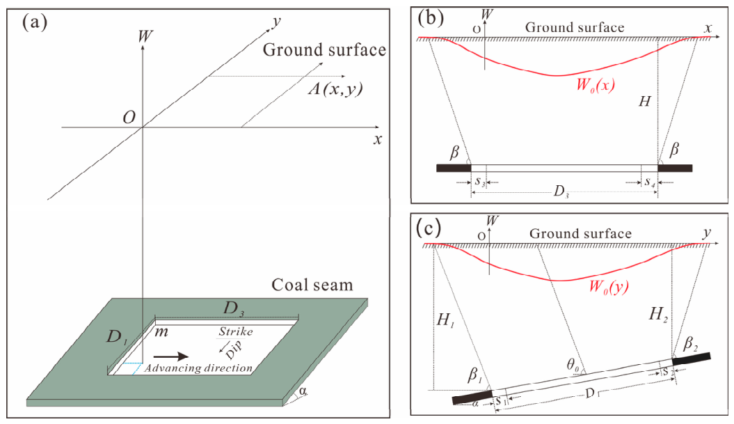
The probability integral method (PIM) is widely used in China for predicting mining-induced surface movement [13]. The principal PIM parameters play distinct roles in governing the magnitude and geometry of a mining-induced subsidence basin. The subsidence coefficient q primarily controls the maximum subsidence; the tangent of the major influence angle, tan β , governs the major influence radius and thus affects the basin width and marginal gradient; the inflection-point offsets S 1 S 4 define the positional offsets between the working-face boundaries and the corresponding inflection points of the subsidence profile; and the mining influence propagation angle θ 0 controls the effective influence range along the dip direction. Their geometric relationships are illustrated in Figure 1. Because these parameters exhibit pronounced nonlinear coupling and compensatory relationships, inversion results may be sensitive to initial values and parameter interactions when empirical selection or conventional local optimization is used [14,15]. In recent years, particle swarm optimization, genetic algorithms, whale optimization, and other swarm-intelligence algorithms have increasingly been applied to PIM parameter inversion. Nevertheless, in high-dimensional constrained search spaces, these algorithms may still be affected by uneven initial population distributions, insufficient global exploration during the later stages of the optimization process, and substantial variability among repeated runs [16,17,18]. Improving the global search capability and convergence stability of PIM parameter inversion is therefore essential for constructing a reliable baseline subsidence field [19,20].
Meanwhile, recent studies have used InSAR to extract subsidence extents, basin-edge points, or deformation gradients and have combined these observations with PIM results through joint inversion or zonal fusion [21,22]. Existing zonal fusion approaches generally switch between InSAR and PIM results using prescribed thresholds of deformation magnitude, interferometric coherence, or spatial gradient. Such threshold-based switching is sensitive to the selected criterion and may introduce discontinuities at the transition boundaries. In addition, some studies have directly incorporated InSAR observations into PIM parameter inversion. However, when subsidence is severely underestimated near the basin center, observational errors may propagate into the model parameters, thereby weakening the ability of PIM to recover large-magnitude subsidence. Therefore, spatially distributed deformation information from reliable InSAR regions should be incorporated while preserving the physical constraints provided by PIM.
However, the accuracy of complete-basin reconstruction depends on both the reliability of the PIM baseline and the manner in which the spatial information provided by InSAR is incorporated. Improvements in only one of these aspects cannot fully address the simultaneous presence of PIM parameter uncertainty and InSAR underestimation in large-gradient subsidence regions. A reconstruction framework that coordinates reliable PIM parameter inversion with spatially adaptive InSAR correction is therefore required.
Accordingly, this study proposes an integrated framework for reconstructing complete mining-induced subsidence basins by coupling improved RIME-based PIM parameter inversion with subsidence-intensity-constrained SBAS-InSAR residual fusion. Sobol low-discrepancy initialization, a nonlinear adaptive search factor, and a stagnation-triggered perturbation strategy are incorporated into RIME to improve the reliability of the inverted PIM parameters and the resulting baseline subsidence field. The spatial differences between SBAS-InSAR and PIM are subsequently treated as residual corrections, whose contributions are regulated according to the normalized subsidence intensity of the PIM-derived basin. In this manner, the PIM represents the complete basin morphology and large-magnitude central subsidence, while SBAS-InSAR supplements spatially distributed information for correcting local discrepancies. The proposed framework is intended to improve the deformation magnitude, spatial continuity, and local accuracy of complete subsidence-basin reconstruction.

2. Study Area and Data

2.1. Study Area

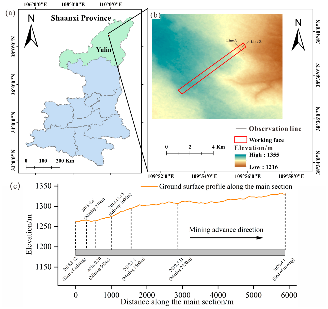
The investigated site is the first working face mined at a large coal mine in northern Shaanxi Province, China. It lies in a coal-producing part of the northern Ordos Basin, at the transition between the northern margin of the Loess Plateau and the Mu Us Sandy Land. The local landscape is dominated by aeolian sandy terrain, sand dunes, and isolated loess ridges and hills. The ground surface is primarily covered by aeolian sand and sparse vegetation, with locally developed seasonal gullies, roads, and a small number of buildings and other structures. Its regional location is presented in Figure 2a.
The target working face is developed in a nearly horizontal thick coal seam with a relatively simple seam structure; the red rectangle in Figure 2b delineates its mining extent. Sandstone and siltstone dominate the roof and floor strata, and the overburden has a relatively stable stratigraphic structure. The mean mining thickness and depth are approximately 7.0 and 340 m, respectively, while the working face extends 5900 m along strike and is 350 m wide. The working face advanced along the strike direction from the setup entry toward the stopping line. Figure 2c shows the ground-surface elevation profile along the strike principal section and the representative working-face positions at selected dates, with the corresponding cumulative advance distances indicated. The surface elevation along this section ranges from approximately 1260 to 1330 m and generally increases in the direction of face advance. Two surface movement observation lines followed the strike and dip directions of the working face, and the black points in Figure 2b denote the observation line. Adjacent points were spaced at an average interval of 25 m. Line Z comprised 32 strike-oriented points (Z01–Z32), whereas Line A comprised 43 dip-oriented points (A01–A43). Control points were placed at the ends of the observation lines or beyond the working-face boundary. Surveys were conducted before, during, and after mining, and point elevations were determined by fourth-order leveling.

2.2. Data Sources

The datasets used for PIM parameter inversion and subsidence-basin fusion comprised surface movement leveling observations and Sentinel-1A synthetic aperture radar (SAR) imagery. The leveling measurements characterized subsidence evolution along the strike and dip principal sections, provided constraints for PIM parameter inversion, and supported the accuracy assessment of different subsidence-field reconstruction methods.
Forty-six C-band Sentinel-1A ascending-pass single-look complex (SLC) images covering the study area formed the SAR dataset. They were acquired between 10 August 2018 and 25 April 2020 in interferometric wide-swath (IW) mode with vertical transmit–vertical receive (VV) polarization. Sentinel-1A IW imagery covers a swath of approximately 250 km, and the SLC products have nominal spatial resolutions of approximately 5 m in range and 20 m in azimuth.
A small-baseline interferometric network was constructed using maximum temporal- and perpendicular-baseline thresholds of 48 days and 200 m, respectively. A total of 174 interferometric pairs satisfying both baseline criteria were retained for subsequent processing. Precise orbit ephemerides were used for orbital refinement, and the Shuttle Radar Topography Mission 1 arc-second digital elevation model (SRTM1 DEM) was used to remove the topographic phase. The differential interferograms were filtered and phase-unwrapped, and pixels with coherence values below 0.3 were excluded from the phase-unwrapping and time-series inversion procedures. Residual orbital and atmospheric phase components were reduced through orbital refinement and spatiotemporal filtering. A stable area outside the mining-affected zone was selected as the zero-deformation reference. The valid interferograms were subsequently inverted and geocoded to obtain the cumulative line-of-sight (LOS) deformation field. For consistent spatial and temporal comparison, the leveling and SBAS-InSAR results were referenced to the same stable area, and 25 April 2020 was adopted as the common endpoint of cumulative deformation.

3. Methods

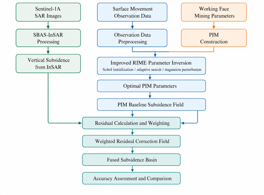
The subsidence-basin reconstruction procedure contains five linked stages: generation of the SBAS-InSAR deformation field, inversion of the PIM parameters, calculation of the PIM baseline subsidence field, weighted correction of the InSAR–PIM residuals, and accuracy assessment of the reconstructed basin. Figure 3 summarizes the complete workflow. Sentinel-1A imagery, leveling observations, and working-face mining parameters are initially processed as separate inputs. The measured surface subsidence profiles then provide the observational constraints for identifying the PIM parameters with the improved RIME algorithm. The parameters obtained from the inversion are used to calculate a physically constrained PIM baseline field. Spatial differences between this field and the SBAS-InSAR vertical subsidence are subsequently extracted, and their contributions are regulated by normalized subsidence intensity. The resulting weighted residual correction is added to the PIM baseline before the reconstruction accuracy is evaluated and compared with those of the individual methods. The proposed framework links PIM parameter inversion and SBAS-InSAR residual fusion through the PIM-derived baseline subsidence field. The improved RIME is first used to obtain the PIM parameters and construct a complete basin-scale subsidence field. The spatial residual between the SBAS-InSAR result and the PIM baseline is then calculated, and its contribution is regulated by normalized subsidence intensity. Through this coordinated procedure, the PIM represents the overall basin morphology and large-magnitude central subsidence, while the spatially distributed SBAS-InSAR information is used to refine local discrepancies, particularly along the basin margins and in low-gradient regions.

3.1. Probability Integral Model

This study adopts the conventional PIM formulation for a rectangular longwall working face [23]. In this formulation, the three-dimensional surface subsidence field is constructed from the strike- and dip-direction principal-section subsidence functions. A local coordinate system is established at one corner of the rectangular working face, with the x -axis parallel to the strike direction and the y -axis parallel to the dip direction, as illustrated in Figure 1 [24]. The subsidence at a surface point (x, y) is expressed as:
W ( x , y ) = W 0 ( x ) W 0 ( y ) W max
where Wmax denotes the maximum subsidence, and W max = m q cos α . Here, m is the mining thickness, q is the subsidence coefficient, and α is the coal-seam dip angle. The terms W 0 x and W 0 y represent the strike- and dip-direction principal-section subsidence functions, respectively.
The strike-direction principal-section subsidence function is expressed as [23]:
W 0 ( x ) = W max 2 e r f π r x e r f π r ( x L )
where the major influence radius r is given by r = H tan β ; in which H is the average mining depth and tan β is the tangent of the major influence angle. The effective calculation length along strike is L = D 3 S 3 S 4 , where D 3 is the working-face length along strike, and S 3 and S 4 are the inflection-point offsets at the setup-entry and stopping-line boundaries, respectively.
Similarly, the dip-direction principal-section subsidence function is expressed as [23]:
W 0 ( y ) = W max 2 e r f π r y e r f π r ( y l )
The effective calculation width l is determined by l = ( D 1 s 1 s 2 ) sin ( θ 0 + α ) sin θ 0 ; where D 1 is the working-face width along dip, θ 0 is the mining influence propagation angle, and S 1 and S 2 are the inflection-point offsets at the two dip-direction boundaries. The geometric definitions of the parameters are illustrated in Figure 1.
The parameter vector involved in the inversion is defined as:
p = [ q , tan β , S 1 , S 2 , S 3 , S 4 , θ 0 ]
Assuming that n surface observation points are available, let W i o b s denote the measured subsidence at the i th point and W i p denote the corresponding model-predicted subsidence. The objective function for parameter inversion is defined as the sum of squared errors:
F p = i = 1 n W i o b s W i p 2

3.2. Basic Principles of the Improved RIME Algorithm

The RIME algorithm is a physics-inspired metaheuristic motivated by the growth of rime ice, an ice deposit formed when supercooled water droplets freeze on exposed surfaces [25]. In the optimization framework, the soft-rime search promotes global exploration, the hard-rime puncture mechanism enhances local exploitation, and greedy selection retains candidate solutions with improved fitness. For PIM parameter inversion, each population member corresponds to one candidate parameter vector. The position of the i th member at iteration t is represented by:
X i t = x i , 1 t , x i , 2 t , , x i , D t
where D is the number of parameters to be inverted.
The original RIME algorithm generally initializes the population using random sampling:
X i 0 = p min + r i p max p min
where p m i n and p m a x the lower- and upper-bound vectors of the parameter space, r i is a random vector within [0, 1] and denotes element-wise multiplication.
To improve the spatial uniformity of the initial candidates, random sampling is replaced by a Sobol low-discrepancy sequence. If S i denotes the i th Sobol point, the corresponding initial population member is obtained from:
X i 0 = p min + S i p max p min
To balance global exploration and local exploitation, a nonlinear adaptive search factor is introduced:
a t = a min + a max a min 1 t T κ
where a t is the search factor at iteration t ; a m a x and a m i n are its maximum and minimum values, respectively; T is the maximum number of iterations; and κ is the nonlinear adjustment coefficient.
During the search process, each candidate solution is updated around the current best solution as follows:
Y i t = X b e s t t + a t R i ( p max p min )
where X b e s t t is the current best candidate and R i is a random vector whose components are uniformly distributed over [−1, 1].
When the change in the best fitness value remains small over several consecutive iterations, the algorithm is considered to have potentially entered a state of local stagnation. In this case, a mixed Cauchy–Gaussian perturbation is applied to the current best solution:
Y b e s t t = X b e s t t + η c C ( 0 , 1 ) p max p min + η g N ( 0 , 1 ) p max p min
where C ( 0 ,   1 ) and N ( 0,1 ) are standard Cauchy and Gaussian random variables, respectively, and η c and η g are the corresponding perturbation-intensity coefficients.
The updated individuals are retained using a greedy selection strategy:
X i t + 1 = Y i t , F ( Y i t ) < F ( X i t ) X i t , F ( Y i t ) F ( X i t )
By incorporating Sobol initialization, an adaptive search factor, and a stagnation-perturbation strategy, the improved RIME algorithm enhances the convergence stability and optimization accuracy of parameter inversion without modifying the structure of the PIM.

3.3. SBAS-InSAR Data Processing

The SBAS-InSAR deformation series was generated from an interferometric network formed using short temporal and spatial baselines. Restricting the network in this manner reduces temporal and spatial decorrelation and supports long-term monitoring of mining-induced surface deformation.
For the j th interferometric pair, the differential phase is represented by [26]:
δ φ j = 4 π λ d L O S ( t B ) d L O S ( t A ) + φ t o p o + φ a t m + φ o r b + φ n o i s e
where δ φ j is the differential interferometric phase, λ is the radar wavelength, and d L O S t A and d L O S t B   are the LOS displacements at the acquisition times of the two SAR images. The remaining terms represent the residual topographic phase, atmospheric delay phase, orbital-error phase, and noise phase, respectively. The ability to recover the deformation phase depends not only on the displacement magnitude but also on the spatial gradient of LOS displacement, interferometric coherence, and phase continuity between adjacent pixels.
After orbit refinement, image coregistration, topographic-phase removal, phase filtering, and phase unwrapping, the valid interferometric observations are assembled into the time-series inversion system:
A v = δ φ
where A is the interferometric-pair connectivity matrix; v is the vector of deformation rates or displacements over successive time intervals to be estimated; and δ φ is the differential-phase observation vector.
Because only ascending-track SAR observations were available, the east–west, north–south, and vertical displacement components could not be independently resolved. The LOS displacement was therefore converted into vertical subsidence under the assumption that the horizontal contribution to the LOS signal was negligible. The InSAR-derived vertical subsidence at an arbitrary point was calculated as [27]:
W I n S A R = d L O S cos θ i n c
where W I n S A R is the InSAR-derived vertical subsidence, dLos is the cumulative LOS displacement, and θ i n c is the radar incidence angle. An average incidence angle of 36 over the study area was used for the LOS-to-vertical conversion. Equation (15) therefore represents a vertical-dominant approximation rather than a decomposition of the full surface displacement field.

3.4. Fusion of the PIM Subsidence Basin and InSAR Residuals

Existing zonal fusion methods generally partition the PIM and InSAR results using prescribed thresholds of deformation magnitude, interferometric coherence, or spatial deformation gradient [28]. Pixels on one side of the threshold are represented by the InSAR observations, whereas those on the other side are represented by the PIM prediction. This binary assignment produces an abrupt change in the selected data source at the zonal boundary and is referred to here as threshold-based switching. Although such methods exploit the complementary characteristics of PIM and InSAR, their performance may be sensitive to threshold selection, and spatial discontinuities may occur at the transition boundaries. To address these limitations, this study proposes an InSAR residual fusion method based on the PIM-derived subsidence basin. First, the subsidence basin predicted by PIM is used to construct a physically constrained baseline field. The differences between the SBAS-InSAR and PIM results are then treated as local residual information, and normalized subsidence intensity is used to control the spatial extent of the residual correction. This approach enables the continuous reconstruction of a complete mining-induced subsidence basin.
Using the optimal parameter vector p b e s t obtained by the improved RIME algorithm, the PIM-predicted subsidence basin is first calculated and adopted as the baseline field for the subsequent residual fusion:
W T ( x , y ) = W P I M ( x , y ; p b e s t )
where W T ( x , y ) denotes the subsidence predicted by the PIM at location (x, y).
At each valid InSAR pixel ( x k , y k ) , the raw spatial residual is:
e I ( x k , y k ) = W I n S A R ( x k , y k ) W T ( x k , y k )
where e I ( x k , y k ) denotes the spatial residual of the SBAS-InSAR result relative to the PIM baseline subsidence field. The residual field is used as a spatial correction term rather than as a direct measure of PIM model error, because it may also contain contributions from atmospheric delay, phase-unwrapping uncertainty, horizontal-displacement projection, and reference-datum differences.
Because InSAR measurements are generally more reliable along basin margins and in low-gradient regions but tend to underestimate deformation in the high-gradient central region [28], the normalized subsidence intensity of the PIM-derived basin is used to control the spatial extent over which the InSAR residuals contribute to the fusion. The normalized subsidence intensity is defined as:
s x , y = W T x , y W T , max
where W T , m a x is the maximum absolute subsidence magnitude of the PIM baseline. Accordingly, s ( x , y ) approaches zero near the basin margin and approaches one toward the basin center.
The contribution weight assigned to the InSAR residual is further defined as:
R s ( x , y ; μ ) = [ 1 s ( x , y ) ] μ
where R s ( x , y , μ ) denotes the contribution weight assigned to the InSAR residual, and μ > 0 is the weight-shape parameter. Because s ( x , y ) represents the normalized subsidence intensity of the PIM-derived basin, smaller values generally correspond to the basin margins and low-gradient regions, whereas larger values mainly correspond to the central high-subsidence region in the present case. The term 1 − s ( x , y ) therefore assigns a relatively large residual contribution to low-subsidence-intensity regions and progressively reduces this contribution as the subsidence intensity increases.
The exponent μ regulates the attenuation rate of the residual weight. When μ = 1, the residual weight decreases linearly with s ( x , y ) . When μ > 1 , the weight decreases more rapidly and the residual correction becomes more concentrated in low-subsidence-intensity regions. When 0 < μ < 1 , the weight decreases more slowly, allowing the residual correction to extend farther toward regions with higher subsidence intensity. Equation (19) thus provides a continuous and adjustable weighting function that reflects the complementary spatial characteristics of SBAS-InSAR and PIM within the subsidence basin.
The weight-shape parameter μ is determined using the measured subsidence at the surface observation points as constraints. At the i th observation point, let W i o b s , W T , i and W I , i denote the measured subsidence, PIM-predicted subsidence, and InSAR-derived subsidence, respectively. The fused subsidence at this point is expressed as:
W F , i ( μ ) = W T , i + R s , i ( μ ) W I , i W T , i
where
R s , i ( μ ) = 1 | W T , i | | W T , max | μ
The optimal weight-shape parameter is selected by minimizing the squared discrepancy between the fused and measured subsidence:
μ = arg   min μ > 0 i = 1 n W i o b s W F , i ( μ ) 2
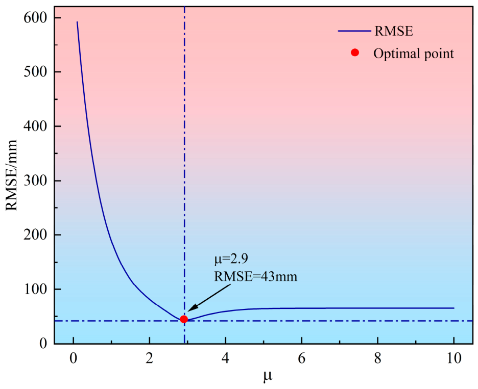
To determine the weight-shape parameter, candidate values of μ ranging from 0.1 to 10.0 were tested at an interval of 0.1. For each candidate value, the residual weight and fused subsidence were calculated at the surface observation points using Equations (21) and (20), respectively. The value producing the minimum discrepancy between the fused and measured subsidence was selected. Because the number of observation points was fixed, minimizing the sum of squared errors in Equation (22) is equivalent to minimizing the corresponding RMSE, which was used to present the parameter-sensitivity results.
The weighted residual field is subsequently constructed as:
e c x , y = R s x , y e I x , y
where e c ( x , y ) denotes the InSAR residual correction constrained by subsidence intensity. For invalid or clearly anomalous InSAR pixels, e c ( x , y ) is set to zero, indicating that no InSAR residual correction is applied to the PIM baseline field in these areas.
To reduce the influence of pixel-scale noise in the InSAR data and ensure the spatial continuity of the residual correction field, the weighted residuals are spatially smoothed or interpolated as:
e ^ x , y = I e c x , y
where e ^ ( x , y ) is the continuous residual correction field, and I denotes a spatial interpolation or smoothing operator, which can be implemented using inverse distance weighting. When the InSAR raster provides complete spatial coverage and contains relatively low noise, the weighted residual field can be used directly as the correction term.
The reconstructed subsidence field is finally obtained as:
W F ( x , y ) = W T ( x , y ) + e ^ ( x , y )
where W F ( x , y ) denotes the reconstructed subsidence field. The PIM-derived field is retained as the baseline throughout the study area, and only the weighted InSAR–PIM residual is introduced as a spatially continuous correction. The normalized PIM subsidence intensity determines the attenuation of the residual contribution from the basin margins toward the center, while the weight-shape parameter is calibrated using the leveling observations. This differs from threshold-based zonal fusion, in which the selected data source changes directly across prescribed boundaries. The resulting formulation preserves the continuity and physical constraints of the PIM basin while allowing local InSAR information to correct marginal and low-gradient discrepancies.

4. Results and Analysis

4.1. Measured Subsidence Characteristics and PIM Parameter Inversion

4.1.1. Subsidence Characteristics of the Measured Profiles

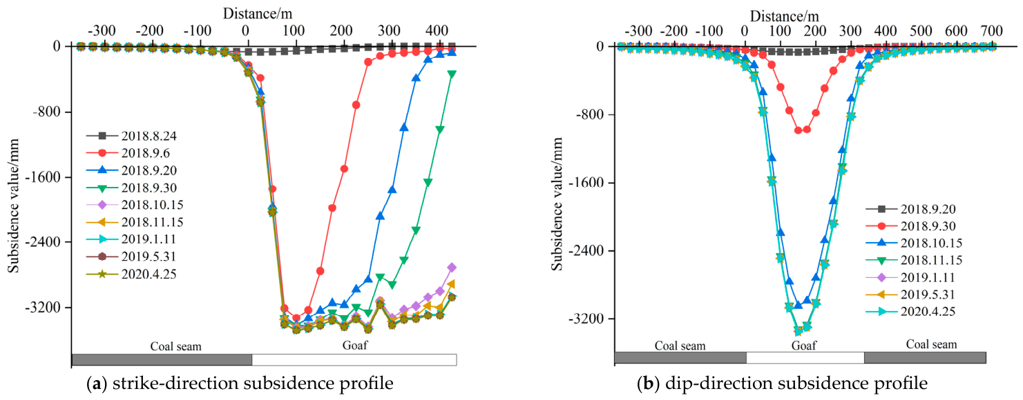
The cumulative subsidence profiles obtained from the strike- and dip-oriented surface movement observation lines were examined to characterize the surface response to working-face extraction. Figure 4 shows the measured profiles along the two principal sections. The representative working-face positions and cumulative advance distances are shown in Figure 2c.
The strike profile in Figure 4a forms a well-defined mining-induced subsidence basin. With continued working-face advance, the affected surface range expanded, and subsidence increased progressively from the panel boundary toward the area above the goaf. By the end of the monitoring period, the maximum cumulative subsidence along the strike principal section had reached 3478 mm at a position approximately 100 m from the setup entry. The profile varies continuously across the basin and gradually converges toward both margins, reflecting the longitudinal development of surface subsidence associated with working-face advance.
The dip-direction profile in Figure 4b also displays a basin-shaped form. Its largest subsidence occurs near the center of the goaf, from which the magnitude decreases toward the two basin margins. The final maximum cumulative subsidence was 3354 mm and was located close to the goaf center. Relative to the strike profile, the dip profile is more symmetric, indicating that the subsidence center is closely aligned with the central part of the working face along the dip direction.
Both measured profiles exhibit the principal morphological characteristics of a mining-induced subsidence basin and maintain good spatial continuity. They therefore provide reliable observational constraints for PIM parameter inversion and for evaluating the accuracy of the reconstructed subsidence fields. The measured surface movement data were subsequently used to determine the PIM parameters and establish the corresponding baseline subsidence field.

4.1.2. PIM Parameter Inversion Results Obtained Using Improved RIME

The PIM parameters were inverted from the measured strike- and dip-direction subsidence profiles using the improved RIME algorithm. Particle swarm optimization (PSO) and the original RIME were used as benchmark algorithms. Identical parameter bounds, population sizes, maximum iteration numbers, and observational data were adopted for all three algorithms to ensure a consistent comparison. Because the three algorithms are stochastic, each algorithm was independently executed 30 times under identical settings. The mean and standard deviation of the RMSE, maximum absolute error, and R 2 were calculated to evaluate the inversion accuracy and stability of the algorithms.
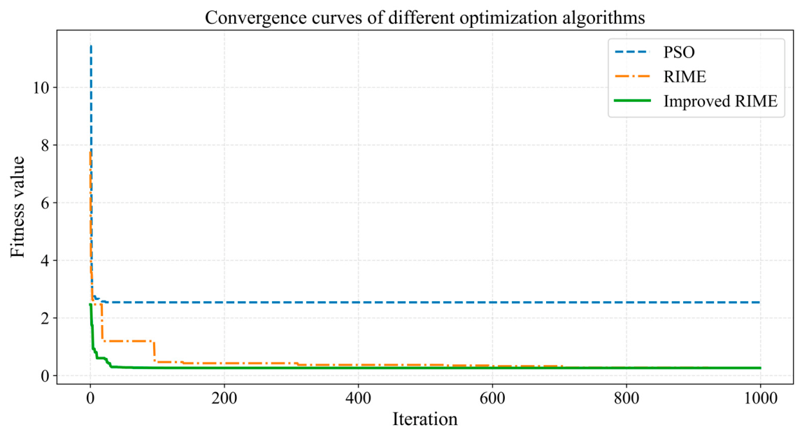
Figure 5 presents the fitness convergence curves of the three algorithms. PSO shows a rapid decrease in fitness during the early iterations, but the objective function decreases only slightly during the later stage, indicating a tendency toward premature convergence. RIME further reduces the objective-function value, although some fluctuations remain during the local refinement stage. In contrast, the improved RIME maintains strong global exploration capability in the early stage and gradually shifts toward local exploitation in the later stage, ultimately achieving the lowest objective-function value. To further evaluate convergence efficiency throughout the iterative process, AUC was adopted as an auxiliary metric. For a parameter inversion problem using the sum of squared errors as the objective function, a smaller AUC indicates that the algorithm approaches a high-quality solution more rapidly and therefore exhibits greater overall convergence efficiency. The AUC of the improved RIME was 87.99% lower than that of PSO and 44.96% lower than that of the original RIME, demonstrating that the proposed improvements substantially enhanced convergence efficiency.
Table 1 lists the PIM parameters obtained using the three algorithms. The improved RIME yielded a subsidence coefficient q of 0.52 and a tangent of the major influence angle tan β of 2.66. The inverted offsets S 1 , S 2 , and S 3 were 81, 91, and 41 m, respectively, corresponding to the two dip-direction boundaries and the setup-entry boundary along strike. The mining influence propagation angle θ 0 was 89.1°. Because the same inflection-point offset was imposed at the two strike-direction boundaries, S 4 was set equal to S 3 . The inverted parameters are consistent with the measured subsidence magnitude and basin geometry. For a mean mining thickness of approximately 7.0 m, q = 0.52 yields a maximum PIM subsidence of approximately 3.64 m for the nearly horizontal coal seam, which is close to the measured maxima of 3.48 and 3.35 m along the strike and dip principal sections, respectively. At a mean mining depth of approximately 340 m, tan β   = 2.66 corresponds to a major influence radius of approximately 128 m. The dip-direction offsets indicate a limited asymmetry between the two basin margins. The value θ 0 = 89.1° indicates an almost vertical propagation direction of mining influence under the nearly horizontal seam condition.
Table 2 summarizes the statistical error metrics obtained from the 30 independent runs. The improved RIME achieved a mean RMSE of 66.7 ± 1.3   mm, representing reductions of 72.28% and 29.86% relative to PSO and the original RIME, respectively. Its mean maximum absolute error was 143.8 ± 4.2 mm, corresponding to reductions of 79.61% and 37.12%, respectively. In addition, its mean R 2 reached 0.990 ± 0.001 . The lower mean errors and standard deviations demonstrate that Sobol initialization, the nonlinear adaptive search factor, and the stagnation-triggered perturbation improve both the inversion accuracy and stability of RIME.
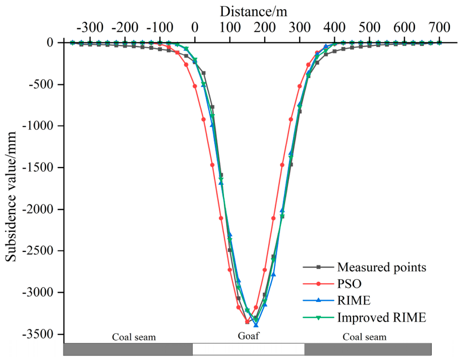
Figure 6 compares the measured dip-direction subsidence profile with the profiles calculated using the three inverted parameter sets. Although the RIME and improved RIME profiles are visually close near the basin center, their differences become more apparent along the basin flanks and marginal convergence zones. The improved RIME more accurately reproduces the variation in subsidence along the basin flanks and the gradual convergence of the profile toward the margins, while maintaining close agreement with the measured central subsidence. Accordingly, the improved RIME parameter set listed in Table 1 was used to construct the PIM baseline field for the subsequent residual-fusion analysis.

4.2. PIM-Predicted Subsidence Basin and SBAS-InSAR Results

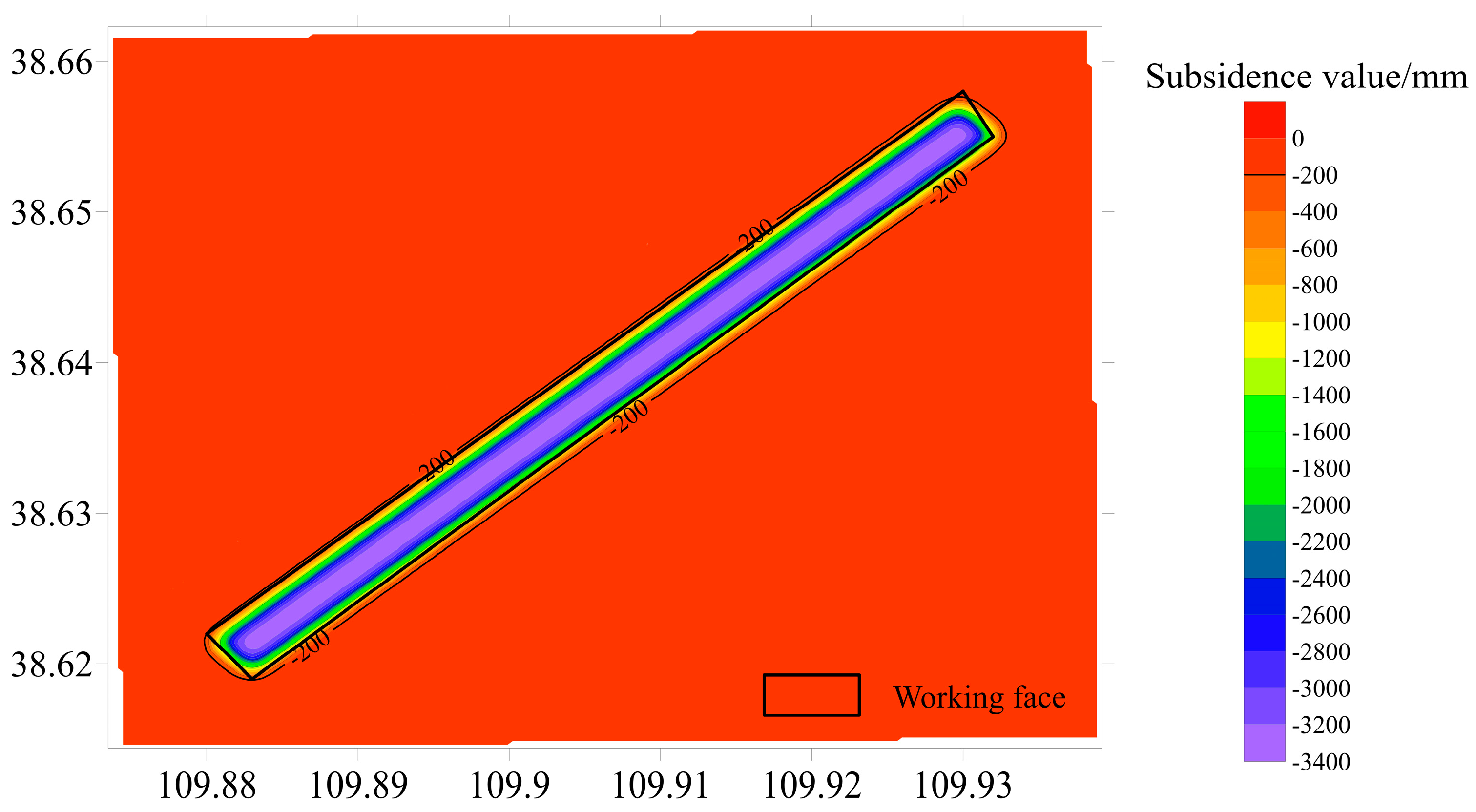
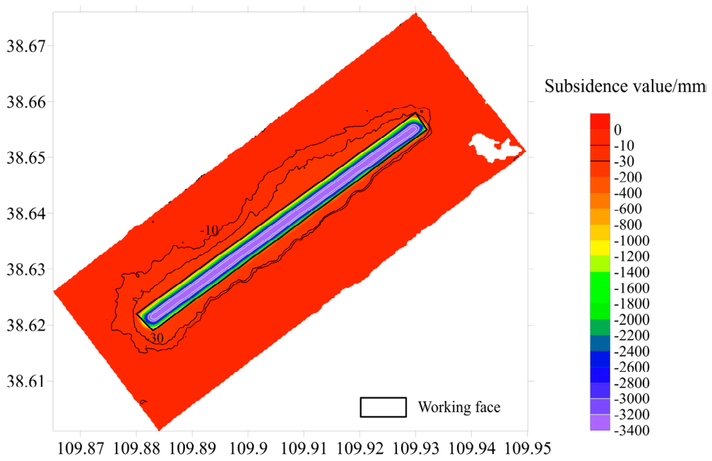
The optimal parameters obtained using the improved RIME were used to generate the PIM-predicted subsidence basin presented in Figure 7. The resulting field is spatially continuous and retains a complete basin morphology. A continuous high-subsidence zone develops above the goaf and extends along the strike direction. From this zone, the subsidence magnitude decreases laterally toward the two dip-direction margins and longitudinally toward the setup-entry and stopping-line boundaries, before approaching a stable value outside the mining influence range.
The maximum PIM-predicted subsidence is approximately 3400 mm and is located mainly above the goaf. The model therefore recovers the large-magnitude central subsidence, the spatial extent of mining influence, and the principal geometry of the basin. These characteristics indicate that the inverted PIM parameters provide a reasonable representation of the overall surface subsidence pattern in the study area.
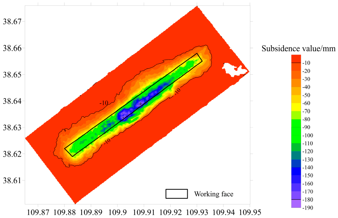
Processing of the 46 ascending Sentinel-1A images yielded the cumulative LOS deformation between 10 August 2018 and 25 April 2020. Under the assumption that the horizontal contribution to the LOS signal was negligible, the LOS displacement was converted to vertical subsidence using the radar incidence angle. The resulting SBAS-InSAR field is presented in Figure 8.
The InSAR-derived deformation forms an elongated belt along the strike direction and spatially corresponds to the working-face position. Subsidence decreases gradually from the deformation zone toward its outer margins. The maximum cumulative vertical subsidence recovered by SBAS-InSAR is approximately 190 mm. Although this value is substantially smaller than the measured large-magnitude subsidence, the spatial pattern confirms that the Sentinel-1A time-series data identify the mining-affected area and provide distributed deformation information near the basin margins and in low-gradient regions.
The PIM and SBAS-InSAR fields are generally consistent in the position, elongation direction, and overall extent of the deformation zone. Both describe a belt-shaped response associated with working-face extraction. Their central subsidence magnitudes, however, differ markedly. The PIM predicts a maximum of approximately 3400 mm, whereas the largest SBAS-InSAR value is about 190 mm, equivalent to only 5.6% of the PIM prediction. The maximum difference between the two results near the basin center is approximately 3.21 m.
The PIM field maintains spatial continuity and represents both the large-magnitude subsidence above the goaf and the overall basin morphology. In contrast, SBAS-InSAR delineates the deformation extent and basin-edge characteristics but does not fully recover the rapid, high-gradient deformation in the central region. The pronounced central underestimation is associated with the spatial concentration of meter-scale subsidence within a relatively narrow zone above the goaf. Such deformation produces steep interpixel LOS displacement gradients and reduces interferometric coherence, thereby weakening the spatial phase continuity required for reliable phase unwrapping. Consequently, valid interferometric observations may be lost in the central region, or the deformation phase may not be correctly recovered during phase unwrapping and subsequent time-series inversion. Toward the basin margins, the deformation magnitude and spatial gradient decrease, allowing SBAS-InSAR to retain more spatially continuous information on the extent and marginal morphology of the subsidence basin.
These contrasting characteristics demonstrate the complementary roles of the two approaches. The PIM reconstructs a physically constrained and spatially complete basin from working-face geometry and strata-movement parameters, whereas SBAS-InSAR contributes spatially distributed observations that are particularly informative near the basin margins. Accordingly, the PIM result was retained as the baseline field, and its spatial differences from SBAS-InSAR were subsequently used as candidate residual corrections.

4.3. InSAR–PIM Residual Characteristics and Subsidence-Intensity Weighting

To ensure the spatial comparability of the SBAS-InSAR and PIM-predicted results, the SBAS-InSAR grid was adopted as the common computational grid. Using the optimal inverted PIM parameters, the corresponding PIM-predicted subsidence was calculated directly at each InSAR grid node. Before residual calculation, stable areas outside the mining-affected zone were used to verify the consistency of the zero-deformation references of the two datasets, and invalid or clearly anomalous InSAR pixels were excluded. The spatial residuals of the InSAR results relative to the PIM baseline subsidence field were subsequently calculated using Equation (17).
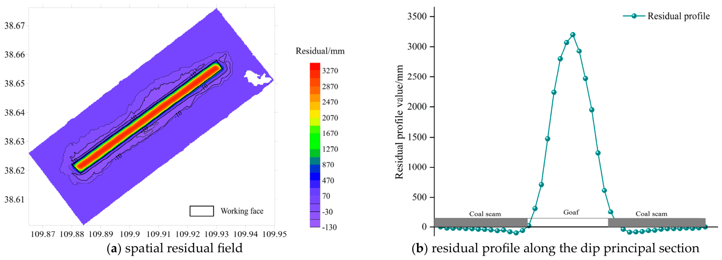
Figure 9 presents the raw InSAR–PIM residual field, with residuals ranging from approximately −130 to 3270 mm and exhibiting pronounced spatial heterogeneity. Positive residuals dominate the central region of the subsidence basin, where the maximum residual reaches 3270 mm, indicating that the subsidence magnitude derived from SBAS-InSAR is substantially smaller than that predicted by the PIM. This discrepancy is primarily associated with decorrelation and phase-unwrapping errors caused by rapid, high-gradient deformation near the basin center. In contrast, the residual magnitudes are relatively small and spatially continuous along the basin margins and in low-subsidence-intensity regions, reflecting local differences between the two results in basin-boundary position and spatial morphology. The dip-direction profile further shows that the residual magnitude increases from the basin margins toward the central high-subsidence region and then decreases toward the opposite margin, providing a clearer sectional representation of the spatial discrepancy between the SBAS-InSAR and PIM results.
To avoid directly partitioning the InSAR and PIM regions using fixed thresholds, residual contribution weights were constructed from the normalized subsidence intensity of the PIM-derived basin. The weight approaches 1 near the basin margins and 0 near the basin center, reflecting the complementary characteristics of the two approaches: SBAS-InSAR retains more spatially continuous information on low-gradient marginal deformation, whereas the PIM provides a stronger physical constraint on large-magnitude subsidence in the high-gradient central region.
Figure 10 shows the RMSE of the fused subsidence at the surface observation points for weight-shape parameter values ranging from 0.1 to 10.0. At relatively small values of μ , the residual weight decreases slowly from the basin margins toward the center, allowing the SBAS-InSAR residuals to affect a relatively large portion of the basin and introducing part of the central underestimation into the fused result. As μ increases, the residual contribution becomes increasingly concentrated along the basin flanks, margins, and low-subsidence-intensity regions. However, an excessively large value causes the residual weight to decrease too rapidly and weakens the correction of local discrepancies. Consequently, the RMSE first decreases and then increases with increasing μ , reaching its minimum value of 43 mm at μ = 2.9 . This result indicates that the selected value provides an appropriate balance between suppressing unreliable central residuals and retaining useful local corrections along the basin margins.
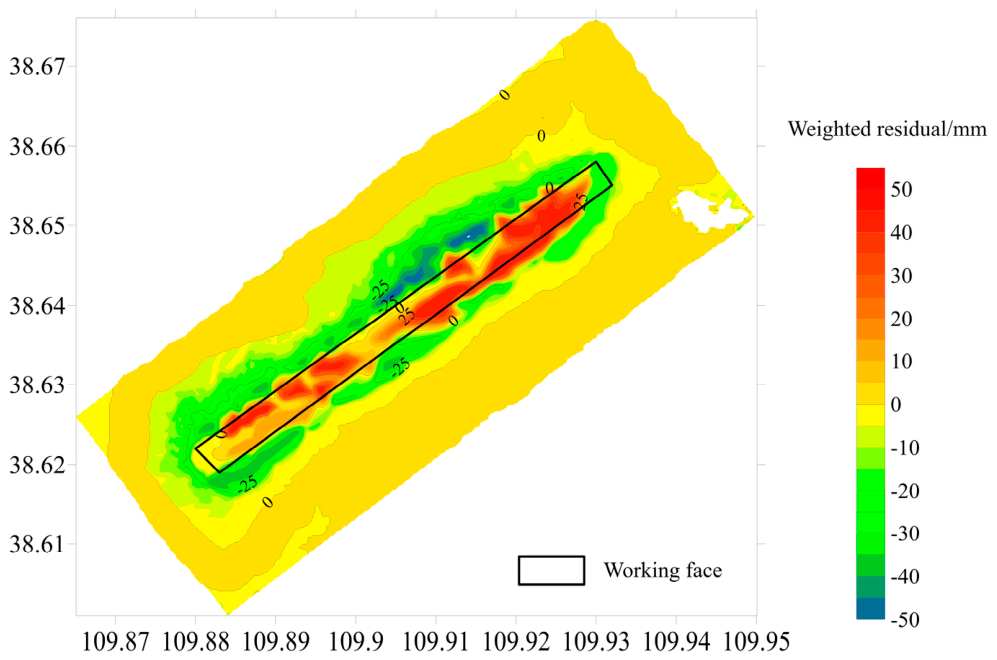
Figure 11 presents the weighted residual correction field calculated using the optimal value of μ . The residual corrections are primarily distributed along the basin margins and in areas exhibiting local spatial discrepancies, while they are substantially attenuated in the basin center. This spatial distribution is consistent with the intended role of the selected weight-shape parameter: it substantially suppresses the influence of the underestimated SBAS-InSAR residuals in the central region while retaining local corrections along the basin margins and in areas of spatial discrepancy.
After subsidence-intensity weighting, the residuals are mainly distributed near the working-face boundaries and in areas of local spatial discrepancy, with their magnitudes generally reduced to approximately −50–50 mm. The positive residuals of several thousand millimeters in the central region of the raw residual field are substantially suppressed, demonstrating that the proposed weighting scheme prevents the severe central underestimation in the SBAS-InSAR result from being directly superimposed on the PIM baseline field.

4.4. Reconstruction and Accuracy Assessment of the Fused Subsidence Basin

Using the optimal weight-shape parameter μ = 2.9 , the weighted residual correction field was superimposed on the PIM baseline to obtain the fused subsidence basin shown in Figure 12. The reconstructed field retains the continuous basin morphology and large central deformation of the PIM while incorporating the spatial variations observed by SBAS-InSAR near the basin margins and in local low-gradient areas.
Relative to the standalone SBAS-InSAR field, the fused basin recovers the large-magnitude subsidence above the goaf more effectively. Relative to the PIM-only result, it provides better local agreement with the observed deformation near the basin margins. Thus, the fusion does not replace the PIM field with InSAR measurements but applies spatially constrained corrections to the physically continuous baseline.
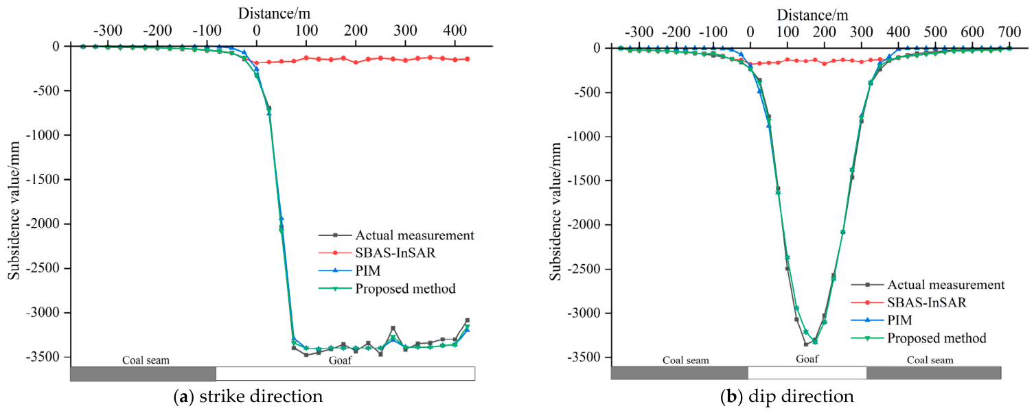
Figure 13 compares the measured, SBAS-InSAR, PIM, and fused subsidence profiles along the strike and dip principal sections. The two sectional comparisons provide a more direct assessment of the reconstruction performance in the principal directions of the subsidence basin. Along the strike direction, the differences among the three reconstruction results are mainly reflected in the recovery of the large-magnitude subsidence above the goaf and the local convergence toward the longitudinal basin margins. Along the dip direction, the fused profile retains the central subsidence represented by the PIM while showing improved agreement with the measured profile in the marginal regions. The results along the two principal sections demonstrate the overall improvement achieved by the proposed residual-fusion method.
Table 3 presents the accuracy metrics for the three subsidence-field reconstruction results. Compared with SBAS-InSAR, the proposed method reduced the RMSE from 1153 to 43 mm and the MAE from 554 to 25 mm, corresponding to reductions of 96.27% and 95.49%, respectively. Compared with the PIM, the RMSE decreased from 65 to 43 mm and the MAE from 52 to 25 mm, representing reductions of 33.85% and 51.92%, respectively. These reductions confirm that the improvement observed in Figure 13 is quantitatively significant. In particular, the proposed method preserves the ability of the PIM to represent large-magnitude central subsidence while improving the agreement with the measured profile in the marginal regions.
Overall, the subsidence-intensity-constrained residual fusion method incorporates spatially distributed SBAS-InSAR observations while preserving the overall continuity and physical constraints of the PIM-derived subsidence basin. It effectively compensates for the central underestimation of InSAR and the local marginal deviations of the PIM, thereby enabling the continuous reconstruction of a complete mining-induced subsidence basin.

5. Discussion

5.1. Influence of PIM Parameter Inversion Accuracy on the Fusion Results

The PIM parameters jointly determine the subsidence amplitude, spatial coverage, and edge-convergence behavior of the predicted basin. Among them, the subsidence coefficient primarily controls the overall deformation magnitude. The tangent of the major influence angle, together with the inflection-point offsets, governs the basin width and the rate at which the profile converges toward its margins, whereas the mining influence propagation angle defines the effective calculation range along the dip direction. Because these parameters are nonlinearly coupled and may compensate for one another, different parameter combinations can produce similar fitting errors when the number or spatial distribution of observation points is insufficient. A small profile-fitting error alone therefore does not ensure that the inverted parameter set is unique.
In this study, Sobol low-discrepancy initialization, a nonlinear adaptive search mechanism, and a stagnation-triggered perturbation were incorporated into RIME to improve search stability and reduce sensitivity to the initial population and local optima. These modifications strengthen the search performance of the optimizer but do not resolve the structural non-identifiability associated with the observation configuration or the PIM formulation itself.
The accuracy of the inverted parameters directly affects the subsequent residual fusion. Because the subsidence-intensity weight approaches zero toward the basin center, the fused field in this region is governed mainly by the PIM-derived baseline. InSAR residuals cannot compensate effectively for a systematic bias already present in the PIM prediction. Reliable parameter inversion is therefore a prerequisite for recovering large-magnitude central subsidence. Future studies should combine parameter-sensitivity analysis and confidence-interval estimation to further quantify parameter uncertainty and evaluate how it propagates into the reconstructed subsidence field.

5.2. Physical Interpretation of Residual Fusion

The proposed method can essentially be regarded as a spatial residual correction approach constrained by a physical model. The PIM baseline field represents the overall basin morphology, spatial extent, and central subsidence magnitude, whereas SBAS-InSAR supplements spatially distributed deformation information along the basin margins and in local low-gradient regions. Unlike methods that apply threshold-based zonal switching between the two results, the proposed method retains the PIM baseline field throughout the entire study area and superimposes only the weighted InSAR–PIM residuals as a continuous correction term. This formulation avoids abrupt boundary discontinuities caused by the direct mosaicking of different data sources.
The scientific significance of this formulation lies in the coordinated treatment of the basin-scale PIM field and the local spatial information provided by SBAS-InSAR. The accuracy of the PIM parameter inversion determines the reliability of the overall basin morphology and central subsidence magnitude, whereas the residual-weighting model determines the extent to which the SBAS-InSAR information contributes to local correction. These two components therefore perform complementary functions within the reconstruction process. Their combination improves the representation of large-magnitude central subsidence while refining the marginal morphology and local spatial variations in the basin, thereby providing a more complete description of mining-induced surface deformation than either dataset alone.
The weight-shape parameter controls the rate at which the residual correction decays from the basin margins toward the center. Determining this parameter using measured surface observations allows the spatial extent of the residual contribution to adapt to the actual subsidence characteristics of the study area and reduces the subjectivity associated with manually specified thresholds.
It should be emphasized that the InSAR–PIM residuals do not exclusively represent local discrepancies between actual surface subsidence and the PIM prediction. They may also contain atmospheric delays, phase-unwrapping errors, horizontal-displacement projection effects, and reference-datum errors. The subsidence-intensity weight should therefore be interpreted as a prior reliability constraint based on the spatial position within the subsidence basin. Its primary purpose is to suppress the propagation of unreliable residuals from the central region into the fused result, rather than to interpret all residual components as actual strata-movement responses.

5.3. Applicability and Limitations

The proposed framework is intended for mining areas where working-face geometry, surface observation profiles, and cumulative SBAS-InSAR deformation measurements are simultaneously available. It is particularly applicable when SBAS-InSAR can delineate the mining-affected area and basin margins but substantially underestimates deformation in the high-gradient central region, and when the PIM remains suitable for representing the overall morphology of the subsidence basin.
The present evaluation, however, is based on a single nearly horizontal thick-coal-seam working face in northern Shaanxi and one ascending-track Sentinel-1A time series. The results therefore demonstrate the feasibility of the framework under the investigated conditions but do not establish its performance across different geological structures, mining layouts, topographic settings, or SAR acquisition geometries. In particular, the calibrated weight-shape parameter of 2.9 and the reported reductions in RMSE and MAE are case-specific and should be recalibrated and re-evaluated when the method is applied to other mining areas.
The available leveling observations were used to constrain the PIM parameter inversion, calibrate the weight-shape parameter, and evaluate the reconstruction accuracy. Consequently, the reported error metrics quantify the agreement achieved within the present case study rather than fully independent predictive performance. Independent validation observations and applications to additional working faces or mining areas are therefore required to evaluate the transferability and generalization of the framework.
The performance of the method also depends on the quality and spatial representativeness of the surface observations and on the accuracy of the PIM-derived baseline. Because only ascending-track SAR observations were available, the LOS displacement was converted into vertical subsidence using a vertical-dominant approximation. Horizontal movement may therefore contribute to local differences between the InSAR-derived and PIM-predicted subsidence fields, particularly along the basin slopes and margins. In addition, the current residual weight is based primarily on the PIM-predicted subsidence intensity and does not explicitly incorporate interferometric coherence, land-cover conditions, atmospheric artifacts, or seasonal variations in data quality. Future work should incorporate ascending- and descending-track InSAR, GNSS or horizontal-displacement constraints, additional InSAR reliability indicators, and independent multi-site validation. Multisource observations may also improve the spatial completeness and accuracy of mining-deformation monitoring [29,30].

6. Conclusions

This study developed an integrated framework for the complete reconstruction of mining-induced subsidence basins by combining improved RIME-based PIM parameter inversion with subsidence-intensity-constrained SBAS-InSAR residual fusion. The improved parameter inversion enhances the reliability of the PIM-derived baseline field, while the residual-weighting model regulates the spatial contribution of the SBAS-InSAR information. The resulting framework combines the capability of PIM to represent the complete basin morphology and large-magnitude central subsidence with the spatially distributed information provided by SBAS-InSAR for local correction. The principal findings are as follows:
(1)
The RIME variant developed for PIM parameter inversion combines Sobol low-discrepancy initialization, a nonlinear adaptive search factor, and a stagnation-triggered perturbation improved the accuracy and stability of RIME in the PIM parameter search. Across 30 independent runs, the improved RIME achieved a mean RMSE of 66.7 ± 1.3 mm, a mean maximum absolute error of 143.8 ± 4.2 mm, and a mean R 2 of 0.990 ± 0.001 . Its area under the convergence curve was 87.99% lower than that of PSO and 44.96% lower than that of the original RIME, indicating improved convergence efficiency within the parameter ranges considered.
(2)
The PIM and SBAS-InSAR exhibited clear complementarity in reconstructing the mining-induced subsidence field. The PIM predicted a maximum subsidence of approximately 3400 mm and preserved both the continuous basin morphology and the large-magnitude central subsidence. By contrast, SBAS-InSAR derived a maximum cumulative vertical subsidence of approximately 190 mm and successfully identified the mining-affected area, but substantially underestimated deformation near the basin center. The raw residuals between the two results ranged from approximately −130 to 3270 mm, with the largest positive residuals concentrated primarily in the central region.
(3)
The subsidence-intensity-constrained residual correction retained the PIM-derived field as the continuous baseline and regulated only the spatial contribution of the InSAR–PIM residuals. With the weight-shape parameter calibrated to 2.9 using the leveling observations, the correction was suppressed in the high-subsidence central region and retained mainly along the basin margins and in low-gradient regions. The fused result achieved an RMSE of 43 mm and an MAE of 25 mm, representing reductions of 33.85% and 51.92%, respectively, relative to the PIM result. For the investigated working face, these results demonstrate that the proposed residual correction can improve local reconstruction accuracy while preserving a spatially continuous subsidence field. Its transferability to other mining and observation conditions requires further independent validation.

Author Contributions

Conceptualization, Q.G. and C.Q.; methodology, Q.G. and C.Q.; software, Q.G.; validation, Q.G. and C.Q.; formal analysis, Q.G.; investigation, Q.G.; data curation, Q.G.; writing—original draft preparation, Q.G.; writing—review and editing, Q.G. and C.Q.; visualization, Q.G.; supervision, C.Q. All authors have read and agreed to the published version of the manuscript.

Funding

This research received no external funding.

Institutional Review Board Statement

Not applicable.

Informed Consent Statement

Not applicable.

Data Availability Statement

The original contributions presented in the study are included in the article. Further inquiries can be directed to the corresponding author.

Conflicts of Interest

The authors have no competing interests to declare that are relevant to the content of this article.

Abbreviations

The following abbreviations are used in this manuscript:
AUCArea under the convergence curve
DEMDigital elevation model
DInSARDifferential interferometric synthetic aperture radar
GNSSGlobal Navigation Satellite System
InSARInterferometric synthetic aperture radar
IWInterferometric Wide Swath
LOSLine of sight
MAEMean absolute error
PIMProbability integral method
PSOParticle swarm optimization
RIMERime optimization algorithm
RMSERoot-mean-square error
SARSynthetic aperture radar
SBAS-InSARSmall baseline subset interferometric synthetic aperture radar
SLCSingle-look complex
SRTM1Shuttle Radar Topography Mission 1 arc-second digital elevation model
UAVUnmanned aerial vehicle
VVVertical transmit–vertical receive polarization

References

  1. Bao, J.; Luo, X.; Liu, G.; Chang, L.; Wang, X.; Shi, Y.; Wu, S. An Improved Distributed Scatterers Extraction Algorithm for Monitoring Tattered Ground Surface Subsidence with DSInSAR: A Case Study of Loess Landform in Tongren County. Int. J. Appl. Earth Obs. Geoinf. 2021, 99, 102322. [Google Scholar] [CrossRef]
  2. Liu, Y.; Yang, T.; Zhao, Y.; Ma, K.; Hou, X.; Zhao, Q.; Li, J. Characteristics of Strata Movement and Method for Runoff Disaster Management for Shallow Multiseam Mining in Gully Regions: A Case Study. Int. J. Rock. Mech. Min. Sci. 2023, 172, 105608. [Google Scholar] [CrossRef]
  3. Ma, S.; Qiu, H.; Yang, D.; Wang, J.; Zhu, Y.; Tang, B.; Sun, K.; Cao, M. Surface Multi-Hazard Effect of Underground Coal Mining. Landslides 2023, 20, 39–52. [Google Scholar] [CrossRef]
  4. Du, S.; Wang, Y.; Zheng, M.; Zhou, D.; Xia, Y. Goaf Locating Based on InSAR and Probability Integration Method. Remote Sens. 2019, 11, 812. [Google Scholar] [CrossRef]
  5. Shi, M.; Yang, H.; Wang, B.; Peng, J.; Gao, Z.; Zhang, B. Improving Boundary Constraint of Probability Integral Method in SBAS-InSAR for Deformation Monitoring in Mining Areas. Remote Sens. 2021, 13, 1497. [Google Scholar] [CrossRef]
  6. Fan, H.; Wang, L.; Wen, B.; Du, S. A New Model for Three-Dimensional Deformation Extraction with Single-Track InSAR Based on Mining Subsidence Characteristics. Int. J. Appl. Earth Obs. Geoinf. 2021, 94, 102223. [Google Scholar] [CrossRef]
  7. Yang, D.; Qiu, H.; Ma, S.; Liu, Z.; Du, C.; Zhu, Y.; Cao, M. Slow Surface Subsidence and Its Impact on Shallow Loess Landslides in a Coal Mining Area. CATENA 2022, 209, 105830. [Google Scholar] [CrossRef]
  8. Tan, Z.; Yang, J.; Deng, K. Study on Method of Mining Subsidence Parameters Calculating for Whole Basin of Mining Area Based on SBAS-InSAR. Coal Sci. Technol. 2021, 49, 312–318. [Google Scholar] [CrossRef]
  9. Berardino, P.; Fornaro, G.; Lanari, R.; Sansosti, E. A New Algorithm for Surface Deformation Monitoring Based on Small Baseline Differential SAR Interferograms. Geosci. Remote Sens. IEEE Trans. 2002, 40, 2375–2383. [Google Scholar] [CrossRef]
  10. Raspini, F.; Caleca, F.; Del Soldato, M.; Festa, D.; Confuorto, P.; Bianchini, S. Review of Satellite Radar Interferometry for Subsidence Analysis. Earth Sci. Rev. 2022, 235, 104239. [Google Scholar] [CrossRef]
  11. Zhu, J.; Yang, Z.; Li, Z. Recent Progress in Retrieving and Predicting Mining Induced-3D Displacements Using InSAR. Acta Geod. Cartogr. Sin. 2019, 48, 135–144. [Google Scholar] [CrossRef]
  12. Chen, H.; Zhao, C.; Tomás, R.; Chen, L.; Yang, C.; Zhang, Y. Retrieving the Kinematic Process of Repeated-Mining-Induced Landslides by Fusing SAR/InSAR Displacement, Logistic Model, and Probability Integral Method. Remote Sens. 2023, 15, 3145. [Google Scholar] [CrossRef]
  13. Li, T.; Zhang, H.; Fan, H.; Zheng, C.; Liu, J. Position Inversion of Goafs in Deep Coal Seams Based on DS-InSAR Data and the Probability Integral Methods. Remote Sens. 2021, 13, 2898. [Google Scholar] [CrossRef]
  14. Xu, C.; Zhou, K.; Xiong, X.; Gao, F.; Lu, Y. Prediction of Mining Induced Subsidence by Sparrow Search Algorithm with Extreme Gradient Boosting and TOPSIS Method. Acta Geotech. 2023, 18, 4993–5009. [Google Scholar] [CrossRef]
  15. Yin, H.; Guo, G.; Li, H.; Wang, T.; Yuan, Y. Prediction Method and Research on Characteristics of Surface Subsidence Due to Mining Deeply Buried Jurassic Coal Seams. Bull. Eng. Geol. Env. 2022, 81, 449. [Google Scholar] [CrossRef]
  16. Yang, Z.F.; Li, Z.W.; Zhu, J.J.; Hu, J.; Wang, Y.J.; Chen, G.L. InSAR-Based Model Parameter Estimation of Probability Integral Method and Its Application for Predicting Mining-Induced Horizontal and Vertical Displacements. IEEE Trans. Geosci. Remote Sens. 2016, 54, 4818–4832. [Google Scholar] [CrossRef]
  17. Zhou, B.; Yan, Y.; Dai, H.; Kang, J.; Xie, X.; Pei, Z. Mining Subsidence Prediction Model and Parameters Inversion in Mountainous Areas. Sustainability 2022, 14, 9445. [Google Scholar] [CrossRef]
  18. Hu, J.; Yan, Y.; Dai, H.; He, X.; Lv, B.; Han, M.; Zhu, Y.; Zhang, Y. Prediction Method for Dynamic Subsidence Basin in Mining Area Based on SBAS-InSAR and Time Function. Remote Sens. 2024, 16, 1938. [Google Scholar] [CrossRef]
  19. Wang, T.; Zhao, F.; Wang, Y.; Zhang, N.; Zhou, D.; Diao, X.; Zhao, X. An Algorithm for Locating Subcritical Underground Goaf Based on InSAR Technique and Improved Probability Integral Model. IEEE Trans. Geosci. Remote Sens. 2023, 61, 5214914. [Google Scholar] [CrossRef]
  20. Zhou, B.; Li, S.; Kang, J.; Zhang, L.; Zhang, J.; Li, M. A Probability Integral Method Modified Model for Accurately Characterizing Subsidence at the Boundary of a Mining Area. Sci. Rep. 2025, 15, 21014. [Google Scholar] [CrossRef] [PubMed]
  21. Liu, H.; Yuan, M.; Li, M.; Li, B.; Zhang, H.; Wang, J. An Efficient and Fully Refined Deformation Extraction Method for Deriving Mining-Induced Subsidence by the Joint of Probability Integral Method and SBAS-InSAR. IEEE Trans. Geosci. Remote Sens. 2023, 61, 5208717. [Google Scholar] [CrossRef]
  22. Tao, Q.; Liu, R.; Li, X.; Gao, T.; Chen, Y.; Xiao, Y.; He, H.; Wei, Y. A Method for Monitoring Three Dimensional Surface Deformation in Mining Areas Combining SBAS-InSAR, GNSS and Probability Integral Method. Sci. Rep. 2025, 15, 2853. [Google Scholar] [CrossRef] [PubMed]
  23. Yang, Z.F.; Li, Z.W.; Zhu, J.J.; Preusse, A.; Yi, H.W.; Wang, Y.J.; Papst, M. An Extension of the InSAR-Based Probability Integral Method and Its Application for Predicting 3-D Mining-Induced Displacements Under Different Extraction Conditions. IEEE Trans. Geosci. Remote Sens. 2017, 55, 3835–3845. [Google Scholar] [CrossRef]
  24. Xue, J.; Tang, F.; Tian, Z.; Su, Y.; Yang, Q.; Zhu, C.; Yi, J. Surface Deformation Characteristics and Damage Mechanisms of Repeated Mining in Loess Gully Areas: An Integrated Monitoring and Simulation Approach. Appl. Sci. 2026, 16, 709. [Google Scholar] [CrossRef]
  25. Su, H.; Zhao, D.; Heidari, A.A.; Liu, L.; Zhang, X.; Mafarja, M.; Chen, H. RIME: A Physics-Based Optimization. Neurocomputing 2023, 532, 183–214. [Google Scholar] [CrossRef]
  26. Chi, F.; Liu, G.; Tao, Q.; Xiao, Y. Subsidence Monitoring and Analysis of Yuncheng Coal Mine Combined with SBAS-InSAR and Probability Integral Model. Prog. Geophys. (Chin.) 2025, 40, 0484–0494. [Google Scholar] [CrossRef]
  27. Chai, H.; Hu, J.; Geng, S. SBAS-InSAR Monitoring Method of Ground Subsidence in Mining Areas by Fusion with Measured Data. J. China Coal Soc. 2021, 46, 17–24. [Google Scholar] [CrossRef]
  28. Gao, F.; Chen, Y.; Zhang, G.; Wen, Q. Monitoring and Analysis of Surface Subsidence in Mining Areas of Integrated SBAS-InSAR and Probability Integral Method. Environ. Earth Sci. 2026, 85, 202. [Google Scholar] [CrossRef]
  29. Wang, R.; Wu, K.; He, Q.; He, Y.; Gu, Y.; Wu, S. A Novel Method of Monitoring Surface Subsidence Law Based on Probability Integral Model Combined with Active and Passive Remote Sensing Data. Remote Sens. 2022, 14, 299. [Google Scholar] [CrossRef]
  30. Dai, S.; Zhang, Z.; Li, Z.; Liu, X.; Chen, Q. Prediction of Mining-Induced 3-D Deformation by Integrating Single-Orbit SBAS-InSAR, GNSS, and Log-Logistic Model (LL-SIG). IEEE Trans. Geosci. Remote Sens. 2023, 61, 5222213. [Google Scholar] [CrossRef]
Figure 1. Schematic diagram of the probability integral model. (a) Coordinate system of the PIM. (b) finite extraction subsidence map in the strike direction. (c) finite extraction subsidence map in the dip direction.
Applsci 16 07782 g001
Figure 2. Regional setting and monitoring layout: (a) location and extent of the mining area; (b) working-face layout and surface observation line; and (c) ground-surface elevation profile along the strike principal section and representative working-face positions at selected dates.
Applsci 16 07782 g002
Figure 3. Workflow of the proposed subsidence-basin reconstruction method.
Applsci 16 07782 g003
Figure 4. Measured surface subsidence profiles.
Applsci 16 07782 g004
Figure 5. Objective-function convergence histories of the three optimization algorithms.
Applsci 16 07782 g005
Figure 6. Measured and PIM-inverted dip-direction subsidence profiles obtained using the three optimization algorithms.
Applsci 16 07782 g006
Figure 7. Subsidence basin predicted by the PIM.
Applsci 16 07782 g007
Figure 8. Cumulative vertical subsidence field derived from SBAS-InSAR.
Applsci 16 07782 g008
Figure 9. Raw InSAR–PIM residuals.
Applsci 16 07782 g009
Figure 10. RMSE of the fused subsidence at the surface observation points for different values of the weight-shape parameter μ .
Applsci 16 07782 g010
Figure 11. Weighted residual correction field.
Applsci 16 07782 g011
Figure 12. Reconstructed fused subsidence basin.
Applsci 16 07782 g012
Figure 13. Comparison of measured and reconstructed subsidence profiles along the principal sections.
Applsci 16 07782 g013
Table 1. PIM parameters inverted using different optimization algorithms.
AlgorithmqtanβS1/mS2/mS3/mθ0
PSO0.503.1289884388.5
RIME0.512.7081904188.6
Improved RIME0.522.6681914189.1
Table 2. Statistical error metrics of the optimization algorithms over 30 independent runs.
AlgorithmRMSE/mmAEmax/mmR2
PSO240.0 ± 9.3704.8 ± 27.60.949 ± 0.004
RIME95.1 ± 3.1228.7 ± 8.50.980 ± 0.002
Improved RIME66.7 ± 1.3143.8 ± 4.20.990 ± 0.001
Note: Values are expressed as the mean ± standard deviation of 30 independent runs.
Table 3. Accuracy assessment of different subsidence-field reconstruction methods.
AlgorithmRMSE/mmMAE/mm
SBAS-InSAR1153554
PIM6552
Proposed method4325
Disclaimer/Publisher’s Note: The statements, opinions and data contained in all publications are solely those of the individual author(s) and contributor(s) and not of MDPI and/or the editor(s). MDPI and/or the editor(s) disclaim responsibility for any injury to people or property resulting from any ideas, methods, instructions or products referred to in the content.