Article

Experimental and Numerical Study on the Pyrolysis Pathways of C7H3F13O in Simulated Battery Immersion System


1
China Power International Development Ltd., Hong Kong SAR, China
2
XYZ Storage Technology Co., Ltd., Beijing 102400, China
3
Key Laboratory of Electrochemical Energy Safety, Ministry of Emergency Management, Beijing 100054, China
4
School of Emergency Management and Safety Engineering, China University of Mining & Technology (Beijing), Beijing 100083, China
*
Author to whom correspondence should be addressed.
Appl. Sci. 2026, 16(15), 7731; https://doi.org/10.3390/app16157731
Submission received: 29 June 2026 / Revised: 26 July 2026 / Accepted: 28 July 2026 / Published: 4 August 2026

Abstract

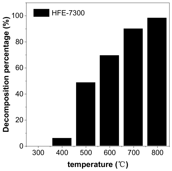
This study investigates the high-temperature pyrolysis pathways and product distribution of the battery immersion coolant HFE-7300 (C7H3F13O) within a simulated thermal runaway environment. Using a tube furnace system combined with GC-MS analysis across a temperature range of 300–800 °C (residence time of 3 s), the thermal stability and cracking evolution were evaluated. Experimentally, HFE-7300 exhibits low initial decomposition at 400 °C with a pyrolysis rate of 5.84%, which rapidly scales up to 48.72% at 500 °C, and reaches a near-complete degradation of 98.46% at 800 °C. Qualitative product characterization identified C2H4, C2F4, C3F6 C4F8, and C5H3F9O as the primary species evolved. To map the micro-scale degradation trajectories, a reaction network comprising 12 elementary pathways was constructed via density functional theory (DFT) calculations at the B3LYP/6-311+G(d,p) level. Using the TST method, we calculated the reaction rate constants for the main decomposition pathways. Analysis reveals that the C4–C5 bond scission pathway (R6) serves as the predominant initial decomposition channel, yielding C5H3F9O and CF2=CF2 as the definitive primary products. These findings provide baseline thermodynamic data and critical safety insights for the engineering design of immersion-cooled battery thermal management systems.

1. Introduction

With the continuous development of the new energy industry and electrification technology, lithium-ion batteries, with their high energy density, long cycle life, and excellent power performance, have been widely used in electric vehicles, new energy storage systems, aerospace equipment, and other fields [1,2,3,4]. They have gradually become an important energy carrier supporting the operation of modern energy systems [5]. However, with the continuous improvement of the energy density and power density of lithium-ion batteries, their operating environments and conditions have become increasingly complex, leading to increasingly prominent safety issues [6,7,8]. Triggered by various factors such as overcharging, external short circuits, internal defects, mechanical shocks, and external heat sources, a series of irreversible exothermic reactions may occur inside the battery [9,10]. This causes the battery temperature to rise rapidly and gradually lose thermal equilibrium, ultimately leading to the thermal runaway process [11]. Among numerous battery thermal management and safety control technologies, immersion liquid cooling technology has attracted widespread attention from academic and engineering fields in recent years due to its advantages of high heat transfer efficiency, uniform temperature distribution, and high system integration [12,13]. Compared with traditional air cooling or indirect liquid cooling methods, immersion liquid cooling can significantly enhance the convective heat transfer process through the direct contact between the liquid cooling agent and the battery surface. Under high heat flux conditions, it introduces a phase change heat absorption mechanism, thereby to a certain extent delaying the trigger time of thermal runaway, reducing the peak battery temperature, and weakening the intensity of thermal disasters [14].
Currently, various thermal management methods have been proposed and applied to ensure the thermal safety of lithium-ion batteries during operation. As a key component of the battery management system, the Battery Thermal Management System (BTMS) is employed to achieve thermal stability and efficiency through the integrated utilization of software, hardware, and related components. The safety and reliability of battery systems can be significantly enhanced, and the risk of thermal runaway effectively reduced, by the implementation of a BTMS. Various cooling strategies have been developed within BTMS, including air cooling, indirect liquid cooling, direct liquid cooling, and phase change material cooling. Among these, immersed liquid cooling, a typical form of direct liquid cooling, achieves temperature regulation by submerging the entire battery in a coolant, allowing heat generated during operation to be absorbed via sensible or latent heat of the liquid.
Research has been conducted on the thermal runaway behavior of lithium-ion batteries under immersion conditions. The results indicate that immersed liquid cooling can mitigate the hazards associated with thermal runaway to some extent. For example, Liu F. et al. [15] investigated seven typical fluorinated liquid coolants, including Novec 7500, and explored the suppression mechanisms of different coolants on the thermal runaway of 18,650 lithium-ion batteries through experimental studies. Jiaxing Li et al. [16] performed thermal runaway experiments on lithium iron phosphate batteries, demonstrating that under overcharge conditions, immersed liquid cooling exerted an inhibitory effect on the occurrence of thermal runaway. Zhendong Zhang et al. [17] examined the thermal runaway behavior of 21,700 cylindrical batteries under immersion conditions, revealing the influence of state of charge and immersion ratio; it was found that the immersion system could reduce the required safety distance between batteries, although peak thermal runaway temperatures still reached 587 °C.
Fluorinated electronic liquids, due to their high thermal conductivity, low energy consumption, excellent electrical insulation, chemical inertness, and non-flammability, have been widely employed in data center liquid cooling systems [8,11,18,19] and are increasingly applied to lithium-ion battery immersion cooling. Among them, ethyl perfluorobutyl ether (HFE-7300, C7H3F13O, CAS: 132182-92-4) is a colorless, odorless, low-toxicity, non-flammable, and well-insulating fluorinated liquid. Its environmental characteristics are favorable, with a global warming potential (GWP) of 200 and an ozone depletion potential (ODP) of 0 [20,21]. The absence of solid particles, oils, and ozone-depleting elements such as chlorine or bromine further enhances its environmental compatibility. HFE-7300 has a boiling point of 98 °C, covering the optimal operating temperature range of lithium-ion batteries, and exhibits strong boiling heat transfer capacity, making it a promising candidate for direct immersion phase change cooling [22,23,24]. In comparison with other common hydrofluoroethers, HFE-7100 and HFE-7200 exhibit boiling points of 61 °C and 76 °C, respectively, whereas HFE-7300 has a boiling point of 98 °C and a longer, branched perfluoroalkyl skeleton. Due to these variations in chemical architecture and physical properties, their thermal stability and decomposition behavior vary significantly. During thermal decomposition, fluorinated compounds are highly prone to producing toxic and corrosive compounds such as HF; therefore, understanding how HFE-7300 decomposes at high temperatures and identifying its primary decomposition products helps in assessing the risks associated with its practical application. However, most existing studies focus primarily on the macro-scale thermal runaway suppression parameters of general fluorinated agents or lower-boiling short-chain variants, while a systematic scientific investigation into the underlying high-temperature pyrolysis pathways and specific gas evolution traits of the longer, branched HFE-7300 skeleton under simulated battery thermal failure fields is still lacking. To address these literature limitations, the uniqueness of this study is that it establishes a comprehensive, high-temperature gradient evaluation network spanning 300–800 °C.

2. Materials and Methods

First, in this paper, all molecular structures were optimized using Gaussian16 software at the B3LYP/6-311G+(d,p) level [25,26,27]. For all molecular structures containing radicals, the UB3LYP/6-311G+(d,p) method was used to optimize the molecular structures and calculate their electronic energies. The electronic energies of all molecular structures in this paper were calculated as the sum of electronic and thermal free energies. Shermo_2.6.1 was used to calculate the Gibbs free energy of all reactants and products, thereby determining the Gibbs free energy changes for all reaction processes [28]. All major reaction processes were verified using a flexibility scan to confirm the presence of energy barriers.
By performing flexible scans to calculate the molecular structures involved in all barrier-free reaction pathways, we obtain the overall changes in molecular free energy along the reaction pathways, The bond length is increased by 0.2 Å at each step; 12 steps are calculated to ensure complete bond breakage. After confirming the absence of a free-energy barrier, we subtract the free energy of the reactants from that of the products and use this difference as the free energy in the TST equation to calculate the chemical reaction rate constant.
The Skodje-Truhlar method was used to calculate the transmission coefficients for reaction processes involving energy barriers, and these coefficients were incorporated into the TST method to calculate the reaction rate constants. All molecular structures containing radicals were checked against S2 to ensure the absence of severe spin contamination.
Subsequently, the actual pyrolysis behavior of HFE-7300 was analyzed through pyrolysis experiments. The experimental setup is shown in Figure 1. The experimental setup used a flow control device to regulate the flow rate of HFE-7300, with N2 serving as the carrier gas, and the mixed gas was fed into a tube furnace. The integrated research framework of this work is schematically summarized in Figure 1. It visually couples the macro-scale experimental loop with the micro-scale theoretical density functional theory (DFT) simulation matrix. The experimental workflow involves programmatic tube furnace pyrolysis, effluent deacidification, and GC-MS characterization. Ultimately, this combination establishes a closed-loop correlation to decode the dominant cracking pathways of HFE-7300.
This article initially employs a tube furnace to simulate the high temperatures generated during the thermal runaway process of lithium-ion batteries. In conjunction with GC-MS, it investigates the thermal decomposition products of HFE-7300 under high-temperature conditions and the decomposition rates at various temperatures.
The GC-MS was from Agilent Technologies, Inc. 7890B-5977B. The specific GC-MS detection parameters were as follows: A DB-5 capillary column (30 m × 0.250 mm × 0.50 μm) was utilized for separation. The column oven temperature program was initiated at 30.0 °C (held for 6.00 min), followed by a ramp to 200.0 °C at a rate of 20.00 °C/min, with a final isothermal hold for 5.00 min. The inlet temperature was maintained at 200 °C. Nitrogen served as the carrier gas with a split ratio of 10:1 and a split flow rate of 9.0 mL/min. The temperatures of the ion source and the transfer line were set to 230 °C and 250 °C, respectively.

3. Results and Discussion

3.1. Gaussian Calculation of Decomposition Pathway

This paper first uses DFT calculations to theoretically investigate the possible thermal decomposition pathways of HFE-7300. The primary thermal decomposition pathway is identified by calculating the reaction rate constants, and the main thermal decomposition products are then analyzed. Given that this paper involves a large number of structures containing free radicals, the S2 values of all structures with free radicals were checked after molecular structure optimization to avoid potential spin contamination. The S2 values for all structures in this paper are around 0.75; for example, the S2 value for the CF2CF3 molecule is 0.7523, indicating that spin contamination has a minimal impact on the theoretical calculation results presented in this paper.
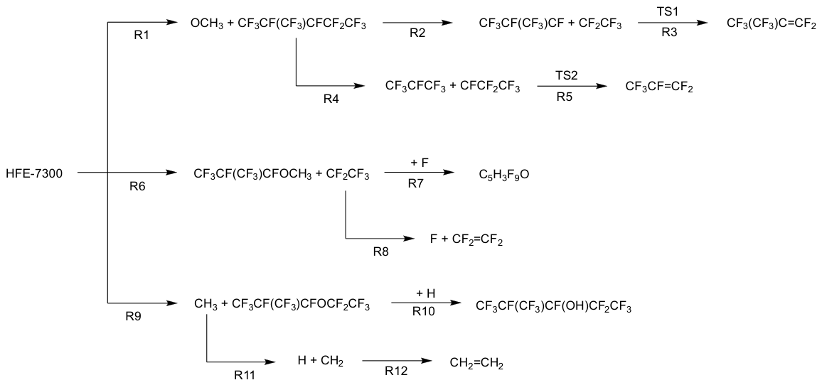
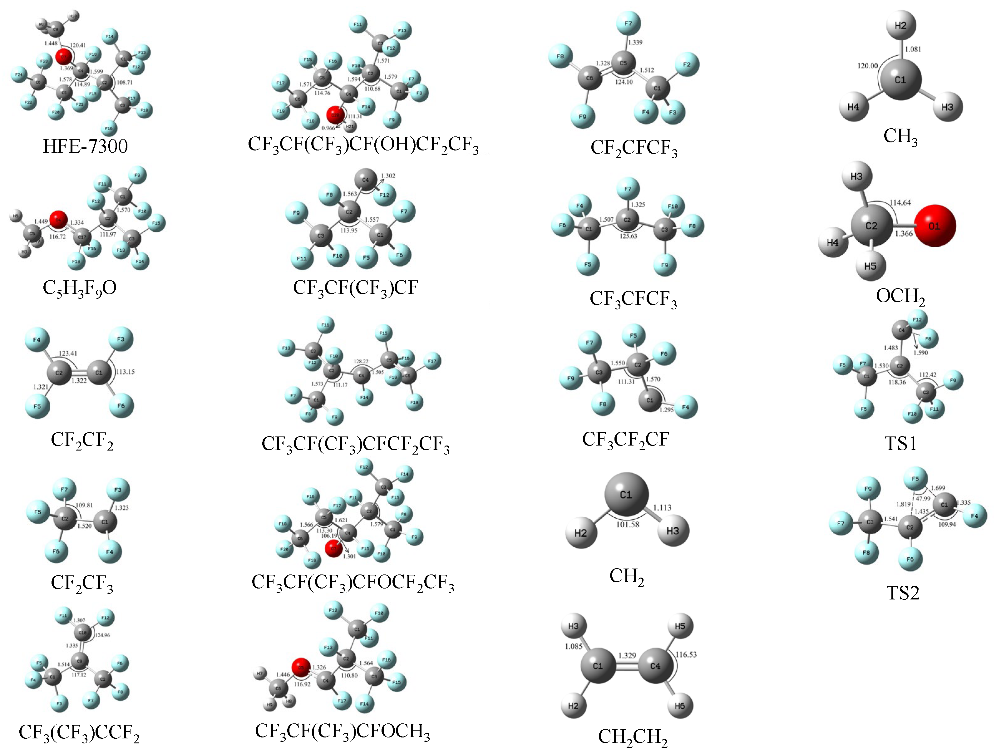
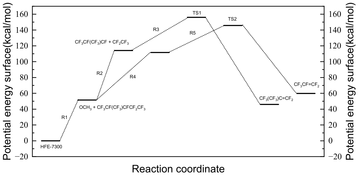
All the molecular involved in this paper has been shown in Figure 2. Compare to other similar work, the structure of HFE-7300 in our article was similar to the structure that been reported before [29]. The pyrolysis pathway of HFE-7300 is shown in Figure 3 and Table 1. There are a total of 12 independent reaction pathways, most of which are simple barrierless reactions. As shown in Figure 4 and Table 2, reaction R1 involves the breaking of the C-O bond in the molecule. Since the bond energy of the C-O bond is generally lower than that of the C-C bond, it is possible for the C-O bond to break preferentially. The breaking of this bond generates two radicals, OCH3 and CF3CF(CF3)CFCF2CF3, which requires the absorption of 51.48 kcal/mol of energy. The CF3CF(CF3)CFCF2CF3 macromolecular radical generated in R1 is unstable and will continue to decompose. In reaction R2, the C4–C5 bond within the radical undergoes homolysis, requiring the absorption of 62.68 kcal/mol of energy to generate CF3CF(CF3)CF and CF2CF3. Subsequently, in reaction R3, the CF3CF(CF3)CF radical undergoes structural rearrangement through transition state 1 (TS1). During this process, a fluorine atom on C2 migrates to the electron-deficient C4 atom, ultimately forming the stable product CF3(CF3)C=CF2. Another fragmentation pathway of this macromolecular radical, reaction R4, breaks the C2-C4 bond, requiring the absorption of 60.14 kcal/mol of energy to generate CF3CFCF3 and CFCF2CF3. Among them, CFCF2CF3 rearranges to CF3CF=CF2 through transition state 2 (TS2). During the rearrangement process, a F atom attached to the intermediate carbon atom migrates to the adjacent CF group, resulting in the conversion of a single carbon–carbon bond to a double bond.
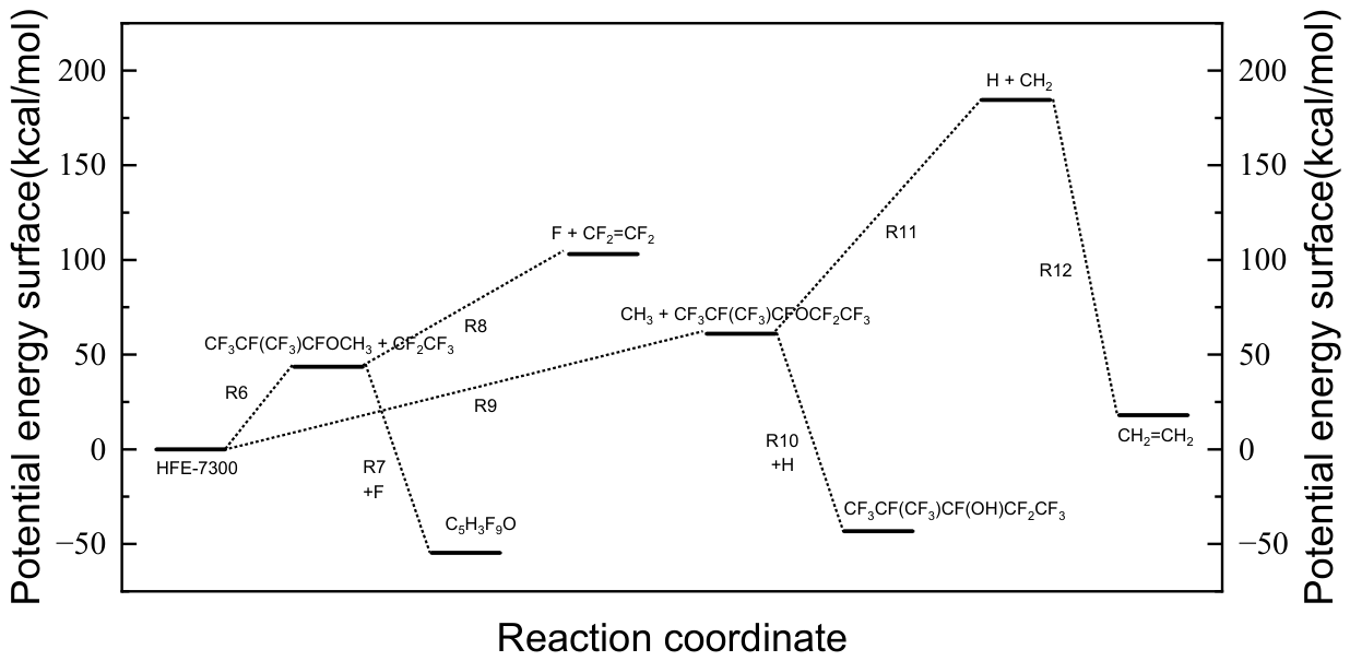
As shown in Figure 5 and Table 3, reaction R6 represents another initial decomposition pathway. In this reaction, the C4–C5 bond breaks, generating CF3CF(CF3)CFOCH3 and CF2CF3 radicals. This process requires the absorption of 43.58 kcal/mol of energy. The CF2CF3 radicals formed in R6 can further react through reaction R8, forming C2F4 by removing a F atom from the CF3 group. This process requires the absorption of 59.58 kcal/mol of energy. The departure of the F atom leads to a redistribution of the electron cloud of the original carbon–carbon single bond, ultimately forming a carbon–carbon double bond. The CF3CF(CF3)CFOCH3 radical, which is generated simultaneously with CF2CF3, has a highly reactive carbon atom at its radical center. This carbon atom can capture a free F atom in the environment through a strongly exothermic reaction R7, releasing 98.29 kcal/mol of energy to generate a stable oxygen-containing final product, C5H3F9O. During this binding process, the carbon atom transitions from a sp2 hybridized planar triangular configuration to a sp3 hybridized tetrahedral configuration, and the molecular geometric structure relaxes to achieve a more stable state.
Reaction R9 is the third initial pathway, involving the breakage of the C8-O bond, generating CH3 and CF3CF(CF3)CFOCF2CF3. This process requires the absorption of 73.60 kcal/mol of energy. The CF3CF(CF3)CFOCF2CF3 radical generated by R9 can capture a hydrogen atom through the strongly exothermic reaction R10, directly forming the stable alcohol product CF3CF(CF3)CF(OH)CF2CF3. This process releases 104.31 kcal/mol of energy. On the other hand, the simultaneously generated CH3 can undergo further transformation. In reaction R11, a C-H bond absorbs 123.05 kcal/mol of energy and undergoes homolysis, generating H and CH2 radicals. Subsequently, two highly reactive CH2 radicals combine with each other through reaction R12, with their respective single-electron occupied orbitals overlapping to form a new C-C bond. This process releases 166.46 kcal/mol of energy, ultimately generating C2H4.
Among the three primary initial reaction pathways, R5 requires the lowest energy absorption, indicating that this reaction is more likely to occur in the initial stage. The radical intermediates generated by each pathway, through subsequent elementary steps such as bond breakage, atomic migration rearrangement, elimination, and recombination, collectively constitute the complex pyrolysis reaction network of HFE-7300.

3.2. Analysis of Main Pyrolysis Pathways and Product Distribution

In this subsection, the reaction rate constants for the major thermal decomposition pathways of HFE-7300 are calculated using the TST method, and the major thermal decomposition products are thereby identified.
Since the vast majority of reactions in the pyrolysis process are barrier-free reactions, a flexible scan of the reaction pathways is first performed before calculating the reaction rate constants. The changes in free energy along the reaction pathways are calculated to determine whether free-energy barriers exist. Subsequently, subtract the Gibbs free energy of the reactants from the Gibbs free energy of the products to obtain the free energy barrier. The TST method is used to calculate the reaction rate constants for the barrier-free reaction processes at different temperatures, ultimately identifying the kinetically favorable pyrolysis pathway. For barrierless cleavage pathways (R1, R6, R9), employing the net free energy difference as the activation free energy in transition state theory yields an effective upper-bound kinetic approximation.
By obtaining the molecular structures along the reaction pathways through flexible scanning and calculating the vibrational frequencies for all molecular structures, the imaginary frequencies for reaction pathways R1, R6, and R9 were found to be −106.43, −73.85, and −227.93, respectively. Using the approximate Skodje-Truhlar method, the transmission coefficients for R1, R6, and R9 at 800 °C were calculated to be 1.001, 1.001, and 1.004, respectively. At 300 °C, the transmission coefficients increased slightly, with values of 1.004, 1.002, and 1.016 for R1, R6, and R9, respectively. The calculation results indicate that, under these conditions, the quantum tunneling effect does not play a dominant role.
First, the calculation results indicate that the reaction processes R1, R6, and R9 are all barrier-free reactions. The calculation results are shown in Table 4 and Table 5. The trend of the curves is similar to that of the chemical equilibrium constants, with R6→R7 being the dominant thermal decomposition pathway across the entire temperature range. Reactions R1, R6, and R9 are all endothermic, and their reaction rate constants increase with rising temperature. At 800 °C, the reaction rate constants for R1, R6, and R9 are 10−8.69, 10−5.63, and 10−11.41, respectively. Among them, reaction R6 exhibits the highest reaction rate constant due to its lowest reaction energy barrier, making it superior to R1 and R9 in both thermodynamics and kinetics. Reaction R7 involves the capture of a fluorine atom by the ·CF3CF(CF3)CFOCH radical fragment and is exothermic. Although its reaction rate constant gradually decreases with increasing temperature, it remains significantly higher than that of reaction R8.

3.3. GC-MS Data, Pyrolysis Products at 800 °C

To verify the results of the theoretical calculations presented earlier, we conducted experimental investigations into the pyrolysis process of HFE-7300 at temperatures ranging from 300 to 800 °C by simulating a battery thermal runaway scenario using a tube furnace.
Table 6 presents the main pyrolysis gas products of HFE-7300 under conditions of 300–800 °C. Note that individual relative concentrations were not quantified due to calibration limits, but their thermodynamic dominance is thoroughly evaluated via Keq analytical frameworks in subsequent sections. Among them, C2H4 primarily manifests as characteristic ion peaks with low mass-to-charge ratios (m/z) of 14, 15, 26, 27, and 28, corresponding to CH2+, CH3+, C2H2+, C2H3+, and C2H4+, respectively. In the mass spectrum of C2F4, two characteristic fragment peaks appear at m/z = 50 and 69, corresponding to CF2+ and CF3+, respectively. C3F6 exhibits ion signals at m/z = 69, 100, and 131, where m/z = 100 and 131 can be attributed to C2F4+ and C3F5+, respectively. For fluorinated products with higher carbon numbers, C4F8 mainly presents characteristic ion peaks at m/z = 69, 119, 131, and 181, where m/z = 119 and 181 correspond to C2F5+ and C4F7+, respectively. Additionally, the table detects an oxygen-containing product, C5H3F9O, with characteristic ion peaks at m/z = 15, 69, 119, 169, 181, and 231, where m/z = 169 and 231 can be attributed to C3F7+ and C5H3F8O+, respectively. The residual HFE-7300 bulk exhibits characteristic ion peaks at m/z = 31, 69, 119, 169, and 269, with newly added m/z = 31 and 269 corresponding to CH3O+ and C5F11+ ion signals, respectively.
The pyrolysis results indicate that during the high-temperature pyrolysis process, HFE-7300 undergoes simultaneous reactions such as carbon chain breakage, retention of oxygen-containing structures, and recombination of fluorine-containing fragments, ultimately forming a pyrolysis product system composed of small hydrocarbon molecules, perfluoroolefins, and oxygen- and fluorine-containing organic compounds. The experimental results show that the pyrolysis of HFE-7300 primarily produces C2F4; this finding is consistent with previous theoretical calculations, demonstrating that the theoretical results are relatively reliable.
Under the conditions of a residence time of 3 s and a pyrolysis temperature ranging from 300–800 °C, the variation in pyrolysis rate of HFE-7300 is shown in Figure 6. At 300 °C, HFE-7300 has not begun to decompose, and the pyrolysis rate is 0%. Within the lower temperature range, HFE-7300 already exhibits a high level of pyrolysis, with a pyrolysis rate of only 5.84% at 400 °C. When the temperature rises to 500 °C, the pyrolysis rate rapidly increases to 48.72%. The increase is most pronounced within the 400–500 °C range, indicating that HFE-7300 undergoes significant cracking at lower temperatures, which is beneficial for absorbing heat through rapid initial cracking and controlling the temperature of thermally runaway batteries. Subsequently, the rate of thermal decomposition gradually slows down, with the pyrolysis rate only increasing from 69.58% to 98.46% between 600 °C and 800 °C.
Research results indicate that HFE-7300 exhibits excellent stability, with virtually no decomposition occurring at normal operating temperatures. At the same time, in the event of thermal runaway in lithium-ion batteries, it decomposes rapidly to suppress flame formation and absorb heat to reduce temperature. At 800 °C, its primary decomposition products are C2F4 and C5H3F9O. C2F4 has relatively low toxicity, whereas toxicity data for C5H3F9O are currently unclear. It is recommended that future immersion-type liquid cooling systems for lithium-ion batteries adopt a sealed design, and that protective equipment be worn when handling thermal runaway incidents.

4. Conclusions

In this work, the thermal decomposition of HFE-7300 was investigated by combining density functional theory (DFT) calculations and experimental analysis. DFT simulations at the B3LYP/6-311+G(d,p) level were used to explore the possible decomposition pathways and the formation routes of pyrolysis products, leading to a preliminary pyrolysis reaction network. All stationary points, including reactants, products, intermediates, and transition states, were confirmed by frequency analysis and intrinsic reaction coordinate (IRC) calculations. The potential energy surface was mapped in detail, which allowed the energy barriers and reaction mechanisms to be determined. The pyrolysis products obtained at 800 °C were identified by GC–MS. The proposed reaction network, together with the experimentally identified products, provides a consistent description of the initial decomposition chemistry of HFE-7300.
The experimental results indicate that at 800 °C, HFE-7300 mainly decomposes into C2H4, C2F4, C3F6, C4F8, and C5H3F9O. The pyrolysis rate of HFE-7300 at 400 °C is only 5.84%, and then gradually increases to 69.58% at 600 °C, demonstrating high thermal stability. Theoretical calculations reveal that there are 12 reaction pathways for the pyrolysis of HFE-7300. According to the reaction rate constants calculated by TST method, reactions R6–R7 are the primary decomposition pathways within the temperature range of 300–800 °C. The main reaction products are C5H3F9O and CF2=CF2. This experiment provides a basis for the selection of liquid coolants for lithium-ion batteries in subsequent research.

Author Contributions

Conceptualization, M.H. and X.G.; methodology, M.H.; validation, X.G., B.Z. and M.H.; formal analysis, M.H.; investigation, X.G. and Y.G.; writing—original draft preparation, M.H.; writing—review and editing, B.Z.; visualization, M.H.; supervision, X.K. All authors have read and agreed to the published version of the manuscript.

Funding

This research was supported by Key Laboratory of Electrochemical Energy Safety, Ministry of Emergency Management, No. EES2025KF06.

Institutional Review Board Statement

Not applicable.

Informed Consent Statement

Not applicable.

Data Availability Statement

The original contributions presented in the study are included in the article, further inquiries can be directed to the corresponding author.

Acknowledgments

This research was supported by Key Laboratory of Electrochemical Energy Safety, Ministry of Emergency Management and School of Emergency Management and Safety Engineering, China University of Mining & Technology (Beijing). Figure 2, Figure 3, Figure 4, Figure 5 and Figure 6 were made by Wei Wang (wangwei@cpes.co).

Conflicts of Interest

Author Ming Hu was employed by the company China Power International Development Ltd. Author Xuewen Geng was employed by the company XYZ Storage Technology Co., Ltd. The remaining authors declare that the research was conducted in the absence of any commercial or financial relationships that could be construed as a potential conflict of interest.

References

  1. Rao, Z.; Wang, S. A Review of Power Battery Thermal Energy Management. Renew. Sustain. Energy Rev. 2011, 15, 4554–4571. [Google Scholar] [CrossRef]
  2. Lu, M.; Zhang, X.; Ji, J.; Xu, X.; Zhang, Y. Research Progress on Power Battery Cooling Technology for Electric Vehicles. J. Energy Storage 2020, 27, 101155. [Google Scholar] [CrossRef]
  3. Liu, J.; Li, H.; Li, W.; Shi, J.; Wang, H.; Chen, J. Thermal Characteristics of Power Battery Pack with Liquid-Based Thermal Management. Appl. Therm. Eng. 2020, 164, 114421. [Google Scholar] [CrossRef]
  4. Zhao, J.; Rao, Z.; Li, Y. Thermal Performance of Mini-Channel Liquid Cooled Cylinder Based Battery Thermal Management for Cylindrical Lithium-Ion Power Battery. Energy Convers. Manag. 2015, 103, 157–165. [Google Scholar] [CrossRef]
  5. Fleckenstein, M.; Fischer, S.; Bohlen, O.; Bäker, B. Thermal Impedance Spectroscopy-A Method for the Thermal Characterization of High Power Battery Cells. J. Power Sources 2013, 223, 259–267. [Google Scholar] [CrossRef]
  6. Xu, J.; Ma, J.; Zhao, X.; Chen, H.; Xu, B.; Wu, X. Detection Technology for Battery Safety in Electric Vehicles: A Review. Energies 2020, 13, 4636. [Google Scholar] [CrossRef]
  7. Zhao, Z.; Hu, H.; He, Z.; Iu, H.H.-C.; Davari, P.; Blaabjerg, F. Power Electronics-Based Safety Enhancement Technologies for Lithium-Ion Batteries: An Overview From Battery Management Perspective. IEEE Trans. Power Electron. 2023, 38, 8922–8955. [Google Scholar] [CrossRef]
  8. Lai, X.; Yao, J.; Jin, C.; Feng, X.; Wang, H.; Xu, C.; Zheng, Y. A Review of Lithium-Ion Battery Failure Hazards: Test Standards, Accident Analysis, and Safety Suggestions. Batteries 2022, 8, 248. [Google Scholar] [CrossRef]
  9. Lamb, J.; Jeevarajan, J.A. New Developments in Battery Safety for Large-Scale Systems. MRS Bull. 2021, 46, 395–401. [Google Scholar] [CrossRef]
  10. Yang, W.; Li, C.; Li, X.; Wang, H.; Deng, J.; Fu, T.; Luo, Y.; Wang, Y.; Xue, K.; Zhang, G.; et al. High Flame Retardant Composite Phase Change Materials with Triphenyl Phosphate for Thermal Safety System of Power Battery Module. eTransportation 2024, 20, 100325. [Google Scholar] [CrossRef]
  11. Yang, Y.; Yang, R.; Pan, L.; Ma, J.; Zhu, Y.; Diao, T.; Zhang, L. A Lightweight Deep Learning Algorithm for Inspection of Laser Welding Defects on Safety Vent of Power Battery. Comput. Ind. 2020, 123, 103306. [Google Scholar] [CrossRef]
  12. Chombo, P.V.; Laoonual, Y. A Review of Safety Strategies of a Li-Ion Battery. J. Power Sources 2020, 478, 228649. [Google Scholar] [CrossRef]
  13. Ma, J.; Liu, A.; Zhang, P.; Chen, Y.; Cai, Y. Collaborative Thermal Management of Power Battery and Passenger Cabin for Energy Efficiency Optimization. Energy Convers. Manag. 2023, 293, 117514. [Google Scholar] [CrossRef]
  14. Li, X.; Yang, W.; Yin, L.; Zhang, S.; Wu, Y.; Mao, Y.; Jia, W.; Wu, D.; Chen, K.; Yuan, L.; et al. Advancing Lithium Battery Safety: Introducing a Composite Phase Change Material with Anti-Leakage and Fire-Resistant Properties. eTransportation 2025, 23, 100387. [Google Scholar] [CrossRef]
  15. Liu, F.; Hu, Q.; Jiang, C.; Xu, Y.; Yan, P.; Sui, X. The Suppression Performance of Fluorinated Cooling Agents on the Lithium-Ion Batteries Fire Based on the Accelerating Rate Calorimeter (ARC). Therm. Sci. Eng. Prog. 2023, 42, 101877. [Google Scholar] [CrossRef]
  16. Li, J.; Ou, J.; Zeng, S.; Chen, L.; Qiao, Y.; Tan, Z.; Li, Y.; Wu, W. Immersion Cooling Enabled Thermal Runaway Prevention in Overcharged Batteries: Mechanisms and Metrics. Appl. Energy 2025, 401, 126798. [Google Scholar] [CrossRef]
  17. Zhang, Z.; Sheng, L.; Zhang, H.; Fu, L. Thermal Runaway Avoidance via Liquid-Immersion for Cylindrical Lithium-Ion Batteries: Experimental Characterizations. Int. J. Therm. Sci. 2025, 217, 110047. [Google Scholar] [CrossRef]
  18. Zhou, B.; Ge, M.; Wang, K.; Yoshioka, H.; Han, J.; Qin, L.; Tao, Z.; Wang, W.; Chen, T. Inhibition Effect of Cooling Agent HFE-7100 on Lithium-Ion Batteries (LIBs) Thermal Runaway in the Immersion System. ACS Sustain. Chem. Eng. 2025, 13, 8928–8938. [Google Scholar] [CrossRef]
  19. Cao, Z.; Wu, Z.; Pham, A.-D.; Yang, Y.; Abbood, S.; Falkman, P.; Ruzgas, T.; Albèr, C.; Sundén, B. Pool Boiling of HFE-7200 on Nanoparticle-Coating Surfaces: Experiments and Heat Transfer Analysis. Int. J. Heat Mass Transf. 2019, 133, 548–560. [Google Scholar] [CrossRef]
  20. Rodríguez, A.; Rodríguez, D.; Moraleda, A.; Bravo, I.; Moreno, E.; Notario, A. Atmospheric Chemistry of HFE-7300 and HFE-7500: Temperature Dependent Kinetics, Atmospheric Lifetimes, Infrared Spectra and Global Warming Potentials. Atmos. Environ. 2014, 96, 145–153. [Google Scholar] [CrossRef]
  21. Hsieh, S.-S.; Li, Y.-F.; Huang, C.-F. HFE-7100/HFE-7300 Spray Quenching via a Piezoelectric Atomizer with a Single-Hole Micronozzle. Appl. Therm. Eng. 2020, 175, 115343. [Google Scholar] [CrossRef]
  22. Rausch, M.H.; Kretschmer, L.; Will, S.; Leipertz, A.; Fröba, A.P. Density, Surface Tension, and Kinematic Viscosity of Hydrofluoroethers HFE-7000, HFE-7100, HFE-7200, HFE-7300, and HFE-7500. J. Chem. Eng. Data 2015, 60, 3759–3765. [Google Scholar] [CrossRef]
  23. Kocian, Š.; Knöbel, E.; Klink, S.; Prokopová, O.; Vrbka, P.; Čenský, M.; Fulem, M.; Růžička, K.; Richter, M.; Jäger, A.; et al. Thermodynamic Properties of HFE-7300. Int. J. Thermophys. 2026, 47, 45. [Google Scholar] [CrossRef]
  24. Muñoz-Rujas, N.; Aguilar, F.; García-Alonso, J.M.; Montero, E.A. High Pressure Density and Speed of Sound of Hydrofluoroether Fluid 1,1,1,2,2,3,4,5,5,5-Decafluoro-3-Methoxy-4-(Trifluoromethyl)-Pentane (HFE-7300). J. Chem. Thermodyn. 2018, 121, 1–7. [Google Scholar] [CrossRef]
  25. Hu, C.; Shen, H.; Zhang, S.; Li, H. Methane Pyrolysis in Preparation of Pyrolytic Carbon: Thermodynamic and Kinetic Analysis by Density Functional Theory. Chin. J. Aeronaut. 2020, 33, 1064–1073. [Google Scholar] [CrossRef]
  26. Zhang, D.; Ouyang, H.; Sun, X.; Xu, Z.; Fu, L.; Yan, H.; Guo, Z.; Jiang, J. Experimental and Theoretical Study on the Thermal Stability and Pyrolysis Mechanism of HCFO-1233 Yd.(Z). Results Chem. 2025, 18, 102829. [Google Scholar] [CrossRef]
  27. Huo, E.; Zhang, S.; Xin, L.; Wang, S.; Cai, S.; Zhang, L.; Bai, M. Pyrolysis Mechanism Study of n-Heptane as an Endothermic Hydrocarbon Fuel: A Reactive Molecular Dynamic Simulation and Density Functional Theory Calculation Study. Comput. Theor. Chem. 2022, 1211, 113696. [Google Scholar] [CrossRef]
  28. Lu, T.; Chen, Q. Shermo: A General Code for Calculating Molecular Thermochemistry Properties. Comput. Theor. Chem. 2021, 1200, 113249. [Google Scholar] [CrossRef]
  29. Paul, S.; Mishra, B.K.; Baruah, S.D.; Deka, R.C.; Gour, N.K. Atmospheric Oxidation of HFE-7300 [n-C2F5CF(OCH3)CF(CF3)2] Initiated by •OH/Cl Oxidants and Subsequent Degradation of Its Product Radical: A DFT Approach. Environ. Sci. Pollut. Res. 2020, 27, 907–920. [Google Scholar] [CrossRef] [PubMed]
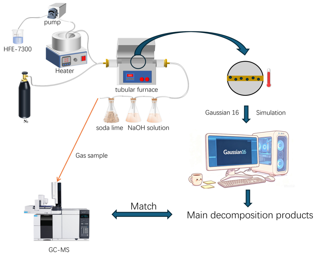
Figure 1. Research mechanism diagram of this work.
Applsci 16 07731 g001
Figure 2. All the molecular and transition state structures are involved in this paper.
Applsci 16 07731 g002
Figure 3. The decomposition pathway of HFE-7300.
Applsci 16 07731 g003
Figure 4. Potential surface of reaction 1–5.
Applsci 16 07731 g004
Figure 5. Potential surface of reaction 6–12.
Applsci 16 07731 g005
Figure 6. The decomposition percentage of HFE-7300 under 300–800 °C.
Applsci 16 07731 g006
Table 1. The reaction formula of HFE-7300 decomposition pathway.
NO.Reaction Formula
1C7H3F13O → ·OCH3 + ·CF3CF(CF3)CFCF2CF3
2·CF3CF(CF3)CFCF2CF3 → ·CF3CF(CF3)CF + ·CF2CF3
3·CF3CF(CF3)CF → TS1 → CF3(CF3)C=CF2
4·CF3CF(CF3)CFCF2CF3 → ·CF3CFCF3 + ·CFCF2CF3
5·CFCF2CF3 → TS2 → CF3CF=CF2
6C7H3F13O → ·CF3CF(CF3)CFOCH3 + ·CF2CF3
7·CF3CF(CF3)CFOCH3 + F → C5H3F9O
8·CF2CF3 → F + CF2=CF2
9C7H3F13O → ·CH3 + ·CF3CF(CF3)CFOCF2CF3
10·CF3CF(CF3)CFOCF2CF3 + H → CF3CF(CF3)CF(OH)CF2CF3
11·CH3 → ·H + ·CH2
12·CH2 → CH2+CH2
Table 2. Electronic energy of the molecular structures involved in Reactions 1–5.
Reaction NumberReactantsProducts
1HFE-7300OCH3CF3CF(CF3)CFCF2CF3
−1642.120911−115.08−1526.958946
2CF3CF(CF3)CFCF2CF3CF3CF(CF3)CFCF2CF3
−1526.958946−951.315981−575.543255
3CF3CF(CF3)CFTS1
−951.315981−951.249287
4CF3CF(CF3)CFCF2CF3CF3CFCF3CFCF2CF3
−1526.958946−813.403568−713.459629
5CFCF2CF3TS2
−713.459629−713.40537
Table 3. Electronic energy of the molecular structures involved in Reactions 6–12.
Reaction NumberReactantsProducts
6HFE-7300 CF3CF(CF3)CFOCH3CF2CF3
−1642.120911 −1066.508276−575.543255
7CF3CF(CF3)CFOCH3FC5H3F9O
−1066.508276−99.775393−1166.440147
8CF2CF3 FCF2CF2
−575.543255 −99.775393−475.673085
9HFE-7300 CH3CF3CF(CF3)CFOCF2CF3
−1642.120911 −39.844281−1602.179454
10CF3CF(CF3)CFOCF2CF3HCF3CF(CF3)CF(OH)CF2CF3
−1602.179454−0.499795−1602.84532
11CH3 HCH2
−39.844281 −0.499795−39.14786
12CH2CH2CH2CH2
−39.14786−39.14786−78.560747
Table 4. Values of the logarithmic form of the reaction rate constant for R1, R6 and R9 at 300 °C and 800 °C, The units of reaction rate constant are s−1.
R1R6R9
300 °C−20.90−16.75−25.16
800 °C−8.69−5.63−11.41
Table 5. Values of the logarithmic form of the reaction rate constant for R7 and R8 at 300 °C and 800 °C, The units of reaction rate constant are s−1 for R8 and s−1M−1 for R7.
R7R8
300 °C27.75−25.78
800 °C8.90−13.09
Table 6. Main gaseous products of the HFE-7300 pyrolysis process.
NumberMass-to-Charge Ratio (m/z)Corresponding Substance
1CH2+(14); CH3+(15); C2H2+(26); C2H3+(27); C2H4+(28)C2H4
2CF2+(50); CF3+(69)C2F4
3CF3+(69); C2F4+(100); C3F5+(131)C3F6
4CF3+(69); C2F5+(119); C3F5+(131)C4F7+(181)C4F8
5CH3+(15); CF3+(69); C2F5+(119); C3F7+(169);
C4F7+(181); C5H3F8O+(231)
C5H3F9O
6CH3O+(31); CF3+(69); C2F5+(119); C3F7+(169); C4F8+; C5F11+(269)HFE-7300
Disclaimer/Publisher’s Note: The statements, opinions and data contained in all publications are solely those of the individual author(s) and contributor(s) and not of MDPI and/or the editor(s). MDPI and/or the editor(s) disclaim responsibility for any injury to people or property resulting from any ideas, methods, instructions or products referred to in the content.