Article

Mechanism of Separation and Fracturing of Vault Strata in Underground Cavities in Gentle-Dipping Bedded Rock Masses

1
State Key Laboratory of Water Engineering Ecology and Environment in Arid Area, Xi’an University of Technology, Xi’an 710048, China
2
Shaanxi Provincial Institute of Water Resources and Electric Power Investigation and Design, Xi’an 710000, China
3
Institute of Geotechnical Engineering, Xi’an University of Technology, Xi’an 710048, China
*
Author to whom correspondence should be addressed.
Appl. Sci. 2026, 16(15), 7517; https://doi.org/10.3390/app16157517
Submission received: 20 May 2026 / Revised: 10 July 2026 / Accepted: 24 July 2026 / Published: 28 July 2026

Abstract

To accurately reveal the mechanism of interlayer separation, crack propagation, and progressive instability of vault strata in underground cavities in gentle-dipping bedded rock masses, this paper systematically elucidates the entire mechanical behavior of separation evolution, crack penetration, structural transformation, and step-by-step caving of vault bedded rock masses under excavation disturbance through a comprehensive integration of excavation unloading mechanical analysis, the Griffith strength criterion, and the dynamic transformation theory of beam structures. The results show that excavation induces radial unloading and circumferential stress concentration in the surrounding rock, and the vault rock mass preferentially undergoes interlayer separation along near-horizontal gentle-dipping bedding planes, forming a spatial zoning feature of gradient attenuation from bottom to top: a strong separation zone at the lower part, a transition zone in the middle, and a closed zone at the upper part. The vault strata undergo a cyclic dynamic structural transformation of cantilever beam–fixed-end beam–simply supported beam, exhibiting stepped fracturing and layer-by-layer caving failure characteristics. The fracture and caving range follow a three-stage evolution law of initial increase–peak–subsequent convergence and stabilization. Based on the elastic mechanics stress transformation relationship, a Griffith initiation criterion for surrounding rock of circular cavities under non-axisymmetric loads is derived and established, and mechanical calculation models of single beam and composite beam suitable for stratified rock masses are constructed, which quantitatively reveal the controlling effects of tensile strength of strata, lateral pressure coefficient, tunnel diameter, stratification thickness, and burial depth on crack initiation and failure degree. Verified by a city-gate-shaped tunnel numerical test and an practical engineering case of a large-scale underground tunnel in western China, the theoretical calculation results are in good agreement with the on-site failure morphology and numerical analysis results. The established separation criterion and mechanical model can effectively predict the initiation risk and stability critical conditions of vault strata. The research results can provide a theoretical basis and technical support for the stability evaluation, early warning, and optimal design of support structures of surrounding rock in underground engineering in gentle-dipping bedded rock masses.

1. Introduction

Bedded rock mass is a typical structural rock mass widely distributed in the shallow crust, and is commonly encountered in major geotechnical engineering constructions such as water conservancy and hydropower projects [1], traffic tunnels [2], underground mine chambers [3], and underground energy storage reservoirs [4]. Among them, gentle-dipping bedded rock masses are characterized by gentle bedding dip angle, densely developed bedding, low interlayer bonding strength, and significant anisotropy and heterogeneity of rock masses [5,6,7]. Under the unloading condition of underground engineering excavation, they are prone to bedding separation, bending fracturing, graded fracture, and layer-by-layer collapse, making them one of the rock mass types with the highest risk of instability and failure of vault surrounding rock in underground cavities [8]. The instantaneous excavation of underground cavities breaks the original three-dimensional in-situ stress equilibrium state, triggering unloading rebound, stress redistribution, and rapid release of deformation energy of the surrounding rock [9]. The vault rock mass rapidly changes from a three-dimensional compression state to a two-dimensional or unidirectional stress state. Under the coupled action of overlying rock weight, tectonic stress, and excavation unloading effect, the vault bedded rock mass undergoes incompatible flexural deformation along weak bedding planes, and interlayer tensile stress accumulates continuously to exceed the tensile strength of bedding planes, thereby inducing progressive chain failure, which seriously threatens the construction safety, structural durability, and long-term operational stability of the tunnel [10].
A large number of engineering practices and studies have shown that the vault failure of underground cavities in gentle-dipping bedded rock masses presents significant temporal and spatial evolution laws [11]: the initial stage of excavation is characterized by the initiation of interlayer microcracks and initial separation; the middle stage is dominated by the instability of spandrel cantilever beams, fracturing of fixed-end beams, and large-scale crack propagation; the later stage ends with stepped layer-by-layer caving and self-organized stabilization of the stress arch. Its failure morphology, propagation path, and evolution mechanism are highly similar to the three-zone development law of “caving zone–fracture zone–bending zone” of overlying strata induced by coal mining [12,13]. However, different from the movement of overlying strata in coal mining, underground cavities are limited spatial structures formed by manual excavation, with more complex constraint boundaries of surrounding rock, significant non-axisymmetric characteristics of the surrounding rock stress field [14], and more sensitive controlling effects of tunnel span, burial depth, lateral pressure coefficient, stratum stratification thickness, and interlayer mechanical parameters on the fracturing mode and failure degree [15,16]. Therefore, directly applying the traditional overlying strata movement theory is difficult to fully characterize the entire mechanical behavior of “separation–fracturing–caving” of vault strata in underground cavities.
In recent years, scholars at home and abroad have carried out extensive research on the failure mechanism of surrounding rock in bedded rock masses [17,18,19,20]. In terms of failure modes, researchers have simplified bedded roofs into structural models such as simply supported beams, fixed-end beams, and cantilever beams, revealing typical failure forms such as bending tensile fracture, shear slip, and compression-induced fracture [21]; in terms of separation evolution, the spatial distribution law of upward propagation of separation and gradient attenuation of opening degree has been clarified through on-site monitoring, physical model tests, and numerical simulations [22,23]; in terms of strength criteria, the Griffith strength theory [24], Mohr-Coulomb criterion [25], and Hoek-Brown criterion [26] have been widely used in the initiation and failure judgment of brittle rock masses. Although abundant achievements have been made in existing studies, there are still three prominent deficiencies: first, the systematic characterization of the complete failure chain of vault strata is insufficient, lacking the whole-process mechanical explanation integrating excavation unloading–interlayer separation–structural transformation–stress arch formation; second, the construction of initiation criteria under non-axisymmetric stress fields is imperfect, and most studies are based on idealized axisymmetric assumptions, which are difficult to apply to real underground cavities with large span, deep burial, and significant influence of tectonic stress; third, the refinement of mechanical models for composite bedded rock masses is insufficient, without fully considering the effects of stratification thickness difference, interlayer debonding effect, and dynamic transformation of boundary constraints on fracturing stress and deformation characteristics, leading to deviations between theoretical calculation results and engineering practice.
Aiming at the above scientific problems and major engineering demands, this paper takes the vault strata of underground cavities in gentle-dipping bedded rock masses as the research object, focuses on the progressive failure mechanism of separation and fracturing, and conducts systematic and in-depth research using a combination of theoretical analysis, mechanical modeling, formula derivation, and engineering verification. Based on the excavation secondary stress field theory, the initial damage evolution and interlayer separation development mechanism of the tunnel vault are revealed; based on the Griffith strength theory, the initiation criterion and analytical calculation formula for surrounding rock of circular cavities under non-axisymmetric loads are derived; through the dynamic structural transformation mechanism, the cyclic transformation of cantilever beam–fixed-end beam–simply supported beam and stepped caving law of vault strata are clarified; mechanical models of single beam and multi-layer composite beam are established, and the calculation method of maximum tensile stress and failure criterion of strata under different constraint conditions are proposed; finally, combined with the engineering case of a large-scale underground tunnel in western China, the theoretical model, separation criterion, and calculation method are verified and applied.
Research objectives of this paper is to establish a whole-process theoretical system of separation–fracturing–instability suitable for the vault of underground cavities in gentle-dipping bedded rock masses, propose quantifiable stratum initiation criteria and structural stress calculation methods, and provide a scientific basis and theoretical support for the stability evaluation, advanced risk early warning, support structure optimization, and long-term safety control of surrounding rock in large-span deep-buried underground cavities.

2. Evolution Mechanism of Separation and Fracturing of Vault Strata in Cavities

2.1. Initial Characteristics of Strata Dominated After Excavation Unloading

Tunnel excavation breaks the equilibrium state of in-situ stress, leading to rapid stress adjustment and deformation energy release of surrounding rock, forming a secondary stress field with radial unloading and circumferential stress concentration.
The elastic stress field components of a circular tunnel under non-axisymmetric external load are:
σ r = 1 2 P 1 + λ 1 a 2 r 2 1 2 P 1 λ 1 + 3 a 4 r 4 4 a 2 r 2 cos 2 θ
σ θ = 1 2 P 1 + λ 1 + a 2 r 2 + 1 2 P 1 λ 1 + 3 a 4 r 4 cos 2 θ
τ r θ = 1 2 P 1 λ 1 + 2 a 2 r 2 3 a 4 r 4 sin 2 θ
where, σ θ is the circumferential stress, σ r is the radial stress, τ r θ is the shear stress, a is the tunnel diameter, P is the confining pressure, and λ is the lateral pressure coefficient.
The radial stress σ r in the vault and tunnel wall decreases sharply, and the circumferential compressive stress σ θ placing the surrounding rock in a tensile-shear composite stress state. Tensile stresses in general rock masses are relatively low, especially along bedding structural planes. According to the Griffith strength theory [27], under the action of horizontal maximum principal stress, the vault surrounding rock preferentially initiates cracks along near-horizontal gentle-dipping bedding planes, and interlayer separation occurs prior to through-layer fracture, providing initial damage conditions for subsequent flexural deformation and structural instability.
After excavation of a tunnel with bedded surrounding rock, the stress of cracked strata can be approximately equivalent to the circumferential stress of the tunnel wall, namely:
σ θ = P 1 + λ + 2 P 1 λ cos 2 θ
At the vault position θ = 90 ° , there is:
σ θ = P 3 λ 1
The above formula shows that the larger the lateral pressure coefficient, the greater the circumferential pressure of the vault. When λ = 1.0 , σ θ = 2 P .
The radial displacement of a circular tunnel under non-axisymmetric external load is:
u r 1 = γ H 1 + μ 2 E 1 + λ a 2 r + λ 1 a 4 r 3 + 1 u 4 a 2 r cos 2 θ
The deformation of the vault is ( θ = π 2 ):
u r 2 = γ H 1 + μ 2 E 1 + λ a 2 r λ 1 a 4 r 3 + 1 u 4 a 2 r
The deformation of the vault tunnel wall is ( θ = π 2 , r = a ):
u r 3 = γ H a 1 + μ E 2 1 u + λ 2 u 1
Excavation unloading directly drives the settlement deformation of vault strata toward the free face inside the tunnel. After losing the support of the lower rock mass, the overlying load is rapidly transferred to the vault strata and the side walls of the tunnel. Due to significant differences in physical and mechanical properties of each stratum in the composite bedded rock mass, asynchronous flexural deformation occurs, forming tensile stress on the contact surface of adjacent strata; when the interlayer tensile stress exceeds the tensile strength of the bedding plane, interlayer separation (separation) occurs. Among them, the lowermost rock mass has the earliest deformation initiation and the largest deformation amount, with the deformation amplitude decreasing layer by layer from bottom to top.

2.2. Evolution Process of Vault Stratum Fracturing and Beam Structure Transformation

The bedding plane is a natural mechanical weak interface of bedded rock mass, characterized by low bonding strength, weak deformation resistance, and easy opening and propagation. The excavation of underground cavities induces unloading and stress redistribution of surrounding rock. Tunnel excavation leads to radial unloading and circumferential stress concentration of surrounding rock. Controlled by weak bedding planes, the vault bedded rock mass has significant differences in interlayer mechanical properties and deflection, showing progressive failure characteristics of bedding separation, graded fracturing, and layer-by-layer caving. Under the combined action of horizontal tectonic stress and overlying strata self-weight, the vault surrounding rock takes the lead in interlayer separation along the weakest near-horizontal bedding plane, forming a separation distribution with gradient attenuation from bottom to top. Its spatial evolution law and mechanical mechanism are highly consistent with the three-zone distribution of “caving zone–fracture zone–bending zone” of overlying strata in coal mining [12,13]. Under the combined action of stress redistribution and interlayer separation, the vault strata undergo a cyclic structural transformation of cantilever beam–fixed-end beam–simply supported beam, with clear stages of fracturing and caving, as shown in Figure 1. The whole process can be divided into 5 stages:
(1)
Initial fracturing stage: The excavation of the tunnel forms a triangular cantilever beam structure at the spandrel, stress concentration at the support produces initial cracks, and the cracks propagate along the bedding plane to both sides of the vault fixed-end beam support.
(2)
Cantilever beam instability stage: The spandrel triangular cantilever beam fractures and caves, the end cracks of the first fixed-end beam of the vault penetrate, the end constraint fails and transforms into a simply supported beam; the mid-span of the simply supported beam is tensioned to produce new cracks, and the supports on both sides of the upper fixed-end beam crack synchronously.
(3)
First simply supported beam failure stage: The first simply supported beam of the vault fractures and caves, the cracks of the fixed-end beam continue to propagate upward, and the upper load transfers to the upper strata.
(4)
Layer-by-layer cyclic failure stage: The second and upper fixed-end beams of the vault successively bear the upper load, penetrate the end cracks and transform into simply supported beams, repeating the process of “mid-span fracturing—end penetration—fracture caving”, and the upper fixed-end beams continuously transform into simply supported beams and cantilever beams.
(5)
Limit equilibrium stage: Under the multi-field coupling action of seepage, temperature, earthquake, etc., the residual cantilever beams gradually fracture and break, and the surrounding rock energy is released step by step, finally forming a self-supporting limit equilibrium arch.
Due to the differences in physical and mechanical properties of each stratum, incompatible flexural deformation occurs between strata, promoting the continuous accumulation of interlayer tensile stress and inducing crack initiation and propagation; key parts such as spandrels and vault ends take the lead in forming cantilever beam structures and fracturing due to stress concentration, thereby driving the vault strata to undergo periodic structural transformation from fixed-end beam-simply supported beam-cantilever beam from top to bottom. The above cyclic transformation forms a stepped groove in the vault, and the failure develops upward in a jumping stepped manner, with the failure symmetry axis perpendicular to the stratum strike and passing through the mid-span of the tunnel.

2.3. Evolution Law of Vault Fracture and Caving Range

The vertical development height, horizontal influence width, and separation propagation scale of vault stratum fracture and caving present a law of continuous initial increase–peak–gradual decrease and stabilization with the failure process, which is the result of the combined action of stress release effect and stress arch self-balancing effect.
(1)
Stage of increasing fracture and caving range (initial excavation–middle failure)
After tunnel excavation, the spandrel cantilever beam is the first to lose stability, the first roof undergoes structural transformation layer by layer, interlayer separation propagates rapidly from bottom to top and to the trailing edge, and the fracture and caving areas continue to expand vertically and horizontally. Stress continuously transfers to the upper surrounding rock, the disturbance range continues to expand, and the number of layers, span, and volume of fracture and caving show a monotonically increasing trend, corresponding to the active expansion period of overlying strata failure.
(2)
Stage of peak fracture and caving range (middle failure)
When the separation and cracks propagate to a certain height, the self-weight constraint of the overlying strata is enhanced, the locking effect of horizontal tectonic stress is prominent, the surrounding rock failure reaches the maximum influence range, and the caving height, horizontal width, and disturbance area all reach extreme values.
(3)
Stage of decreasing fracture and caving range (late failure–stabilization stage)
With the gradual formation of the limit equilibrium arch, the arch structure bears the overlying load and achieves stress self-balancing, and the constraint conditions of surrounding rock are significantly improved; controlled by the roof end effect, the cantilever span of the upper rock mass gradually shrinks, the caving boundary converges toward the mid-span of the tunnel, and only local minor adjustments occur subsequently, without large-scale new fractures and caving; the overall fracture and caving range gradually converges and decreases, and finally stabilizes.
The whole process of separation, fracturing, fracture and caving of vault strata in underground cavities of bedded rock masses is essentially a progressive mechanical response process of excavation unloading–stress redistribution–bedding weakening–structural transformation–stress arch self-balancing. The surrounding rock stress and failure range show significant stage laws. The weak plane effect of bedding plane, excavation stress release effect, stratum incompatible deformation effect, and structural transformation effect caused by boundary constraint weakening jointly control the whole process of separation, fracturing, propagation, penetration, instability and caving of vault rock mass, and determine the evolution mode and final stable morphology of progressive roof failure in underground cavities of bedded rock masses.

3. Separation Mechanism of Bedded Surrounding Rock in Tunnel Vault

3.1. Nature of Fracture in Brittle Materials Such as Rock

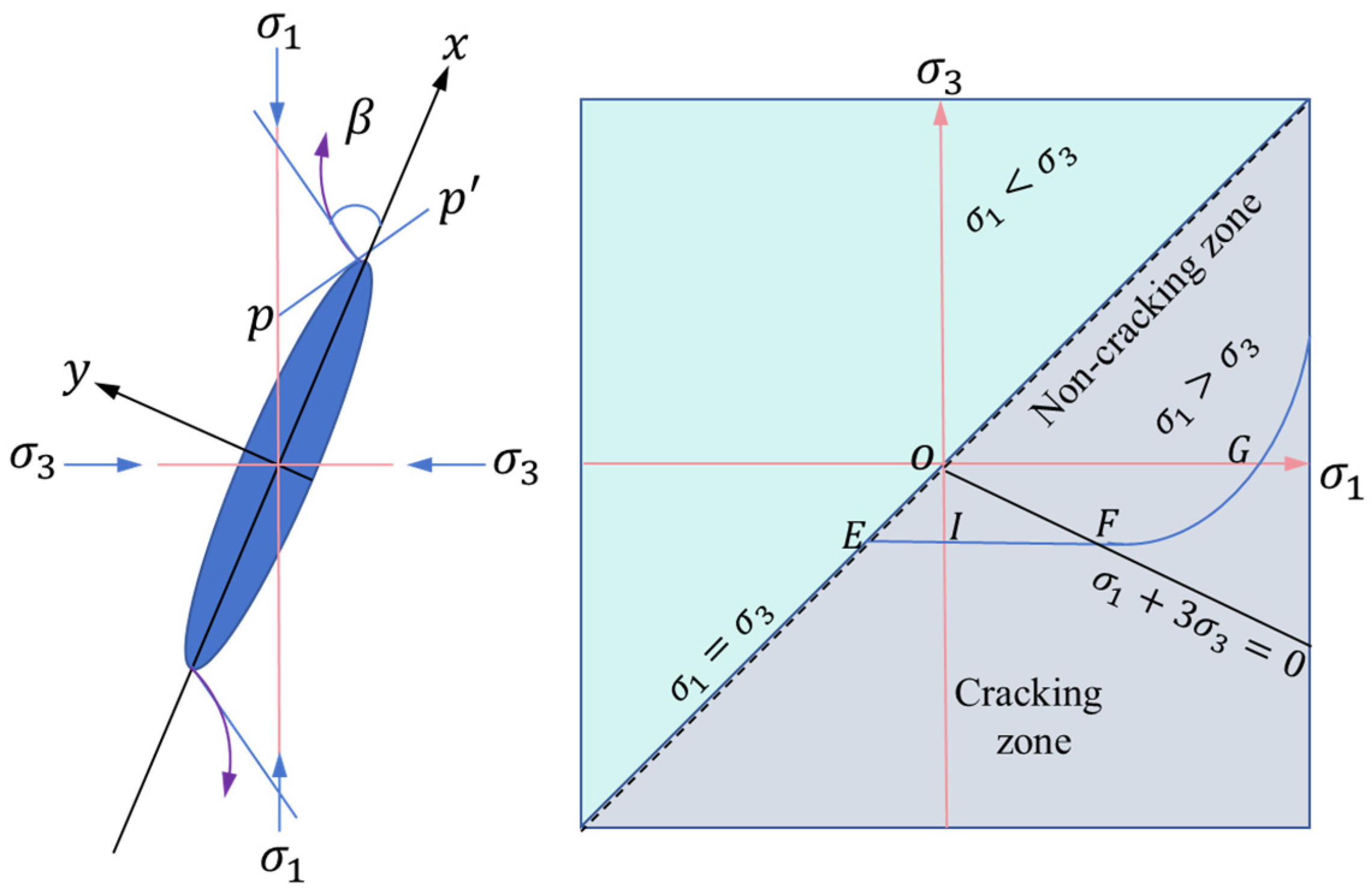
Brittle materials such as rock contain a large number of randomly distributed primary microcracks inside [28]. According to the Griffith strength theory, under external force, severe stress concentration occurs at the tip of microcracks [29], and when the accumulated strain energy reaches a critical value, cracks begin to propagate, as shown in Figure 2. With the increase of external force, cracks propagate along the direction perpendicular to the maximum tensile stress of P P ; under uniaxial compression, the crack tip (the intersection of P P and the crack) is the location of maximum tensile stress, cracks propagate perpendicular to the maximum principal stress direction, and finally transition to parallel to the maximum principal stress direction. This law intuitively reveals that splitting failure is the essential form of rock failure under uniaxial compression. Cracks begin to propagate when the effective stress acting at the crack tip reaches the energy required to form new cracks, that is, the crack initiation meets the energy criterion: σ t = 2 ρ E π c 1 2 , where σ t is the maximum tensile stress at the crack tip, ρ is the specific surface energy of the crack, c is the semi-major axis length of the crack, and E is the elastic modulus. This criterion clearly reveals the mechanical cause, energy condition and propagation direction of brittle material fracture.

3.2. Griffith Strength Theory Initiation Criterion

Based on the analytical solution of an elliptical hole under load in elastic mechanics, the piecewise criterion of Griffith strength in the principal stress σ 1 σ 3 coordinate system with compression as positive is derived, as shown in Figure 2. The lower right of the function curve is the cracking area:
When σ 1 + 3 σ 3 < 0 , the criterion ① is
σ 3 < σ t
When σ 1 + 3 σ 3 > 0 , the criterion ② is
σ 1 σ 3 2 σ 1 + σ 3 > 8 σ t
Criterion ① is a straight line, that is, regardless of the value of σ 1 , rock cracks begin to propagate as long as σ 3 < σ t is satisfied. Criterion ② is a quadratic curve and connects with the straight line segment in ① at the point 3 σ t , σ t . Microcracks are randomly distributed in the rock, and the most favorable crack orientation angle φ for fracture satisfies cos 2 φ = σ 1 σ 3 2 σ 1 + σ 3 .

3.3. Brittle Failure Criterion for Surrounding Rock of Circular Tunnel Under Non-Axisymmetric External Load

The stress characteristics of a circular tunnel under axisymmetric conditions show that the circumferential stress σ θ = σ 1 , the radial stress σ r = σ 3 , and the Griffith initiation criterion of the tunnel surrounding rock can be directly applied to the above formula. However, the stress characteristics of a circular tunnel under non-axisymmetric conditions show the existence of shear stress τ r θ , the circumferential stress σ θ σ 1 , and the radial stress σ r σ 3 . According to the stress circle characteristics, the stress transformation relationship is:
σ 1 = σ θ + σ r 2 + σ θ σ r 2 2 + τ r θ 2
σ 3 = σ θ + σ r 2 σ θ σ r 2 2 + τ r θ 2
At this time, the Griffith strength criterion can be transformed into:
Discrimination condition: σ 1 + 3 σ 3 < 0 , equivalent to
4 τ r θ 2 > 3 σ θ + σ r σ θ + 3 σ r
Criterion ①: σ 3 < σ t , equivalent to
τ r θ 2 > σ t + σ θ σ t + σ r
Criterion ②: σ 1 σ 3 2 σ 1 + σ 3 > 8 σ t , equivalent to
4 τ r θ 2 > 8 σ t σ θ + σ r σ θ σ r 2
When τ r θ = 0 , at the tunnel wall, σ θ σ r , the above formula can be degraded to the discrimination conditions (9) and (10) under axisymmetry.
In summary, the unified initiation criterion for tunnel surrounding rock under non-axisymmetric external load is:
When 3 σ θ + σ r σ θ + 3 σ r < 4 τ r θ 2 , use the criterion ① of Formula (14);
When 3 σ θ + σ r σ θ + 3 σ r > 4 τ r θ 2 , use the criterion ② of Formula (15).

3.4. Analytical Theory of Surrounding Rock Initiation Cracking for Circular Tunnel Under Non-Axisymmetric External Load

According to the selection conditions and criteria of the Griffith initiation criterion, the combined expressions ( σ θ + σ r , σ θ σ r , 3 σ θ + σ r , σ θ + 3 σ r ) of elastic stress components for a circular tunnel under non-axisymmetric external load could be obtained.
Substituting the combined expressions of the stress field into the initiation criterion, and letting 0 < a 2 r 2 = R < 1 , an implicit function about the initiation condition can be obtained:
1 + λ 2 + R + 1 λ 1 + 3 R 2 + 2 R cos 2 θ 1 + λ 2 R + 1 λ 1 3 R 2 + 6 R cos 2 θ < 1 λ 1 + 2 R 3 R 2 sin 2 θ 2
If the criterion selection condition (16) is satisfied, judge according to initiation criterion ①:
1 λ 1 + 2 R 3 R 2 sin 2 θ 2 > 2 σ t P + 1 + λ 1 R 1 λ 1 + 3 R 2 4 R cos 2 θ 2 σ t P + 1 + λ 1 + R + 1 λ 1 + 3 R 2 cos 2 θ
If the criterion selection condition (16) is not satisfied, judge according to initiation criterion ②:
1 λ 1 + 2 R 3 R 2 sin 2 θ 2 > 8 σ t P 1 + λ + 2 1 λ R cos 2 θ 1 + λ R + 1 λ 1 + 3 R 2 2 R cos 2 θ 2
The above formula is an implicit function about θ   and   R . When the tunnel diameter a , lateral pressure coefficient λ , confining pressure P , tensile strength σ t , etc. are known, the initiation cracking state of the surrounding rock at any position r , θ in the tunnel can be judged.

3.5. Initiation Characteristics of Bedded Surrounding Rock in Tunnel Vault

For near-horizontal bedded surrounding rock in the tunnel vault, the average stratification thickness of the vault bedded rock mass is t , and the strata near the tunnel wall satisfy r = a + t , R = a 2 a + t 2 , θ = π 2 . Then the above Formulas (16)–(18) can be further simplified as:
1 + λ 2 + R 1 λ 1 + 3 R 2 + 2 R 1 + λ 2 R 1 λ 1 3 R 2 + 6 R < 0
2 σ t P + 1 + λ 1 R + 1 λ 1 + 3 R 2 4 R 2 σ t P + 1 + λ 1 + R 1 λ 1 + 3 R 2 < 0
8 σ t P 1 + λ 2 1 λ R 1 + λ R 1 λ 1 + 3 R 2 2 R 2 < 0
When λ = 1.0 , the above formula can be further simplified as:
R 2 > 4
R 2 > σ t P + 1 2
R 2 > 4 σ t P
Since 0 < R < 1 , Formula (22) is not valid, so under axisymmetric external load, initiation cracking judgment should be carried out according to Formula (24), and the critical cracking thickness criterion is:
t < 1 4 σ t P 1 4 1 a
The above formula shows that the smaller the tensile strength σ t , the larger the confining pressure P , and the smaller the tunnel diameter a , the smaller the cracking thickness or stratum thickness t . Under the known conditions of tensile strength, confining pressure, and tunnel diameter, the maximum cracking thickness t can be obtained.

4. Fracturing Mechanism of Bedded Rock Mass in Tunnel Vault

The distribution characteristics of the secondary stress field of surrounding rock after tunnel excavation show that the radial stress of the tunnel wall is small and the circumferential stress is dominant. Considering the Griffith strength theory, for the vault surrounding rock under horizontal major principal stress, it is inevitable to crack first along the horizontal direction, that is, first crack along the existing near-horizontal gentle-dipping fractures, interlayer separation occurs first, and the separated bedded strata are mainly subjected to their own gravity and horizontal axial force. After stress redistribution, the vault strata will gradually produce flexural deformation from bottom to top. Considering the interlayer separation characteristics, the influence of interlayer shear force caused by flexural deformation on interlayer dislocation can be ignored, so the interlayer friction force after separation can be neglected in the calculation process, providing a prerequisite for the subsequent establishment of the composite beam model.
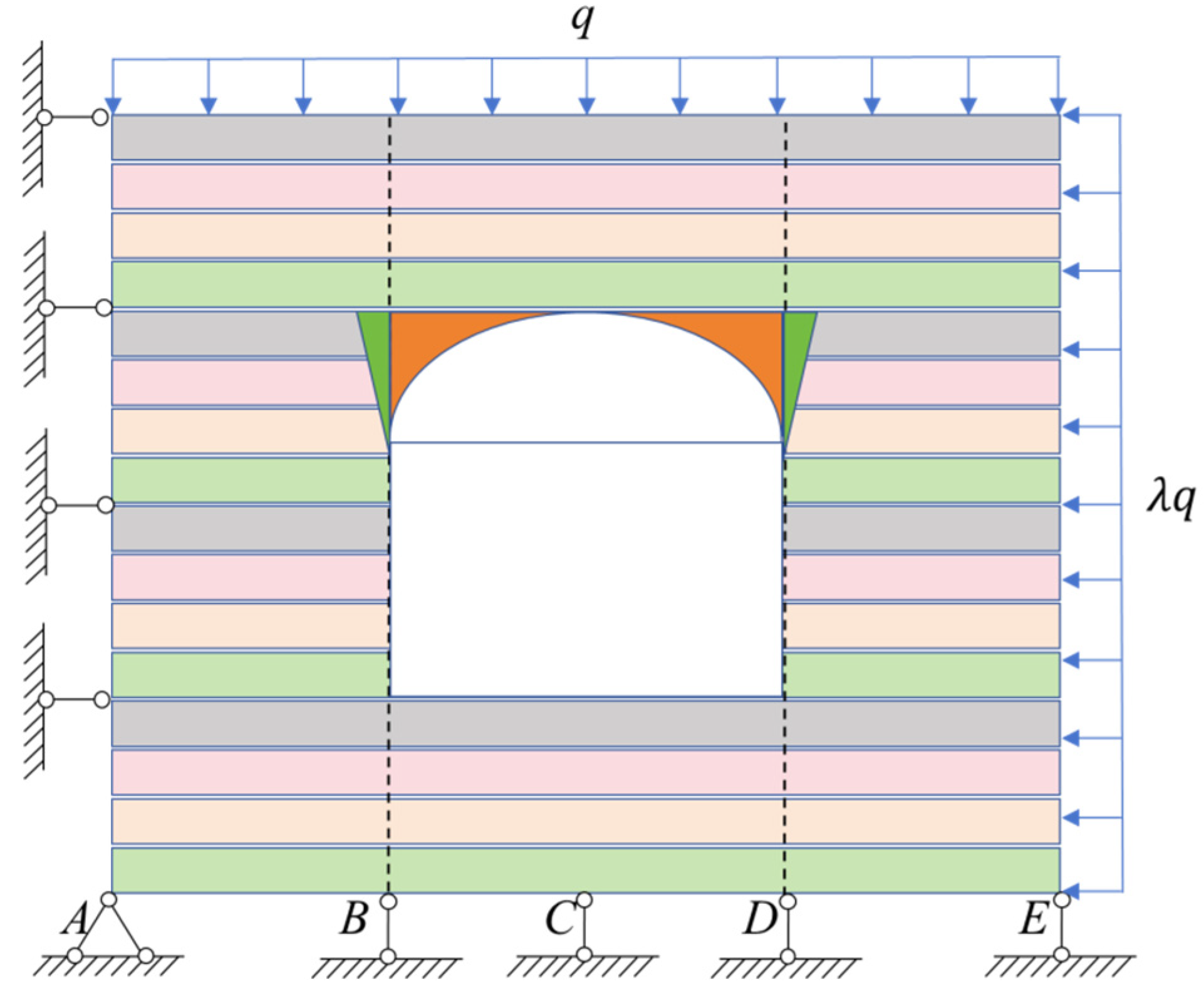
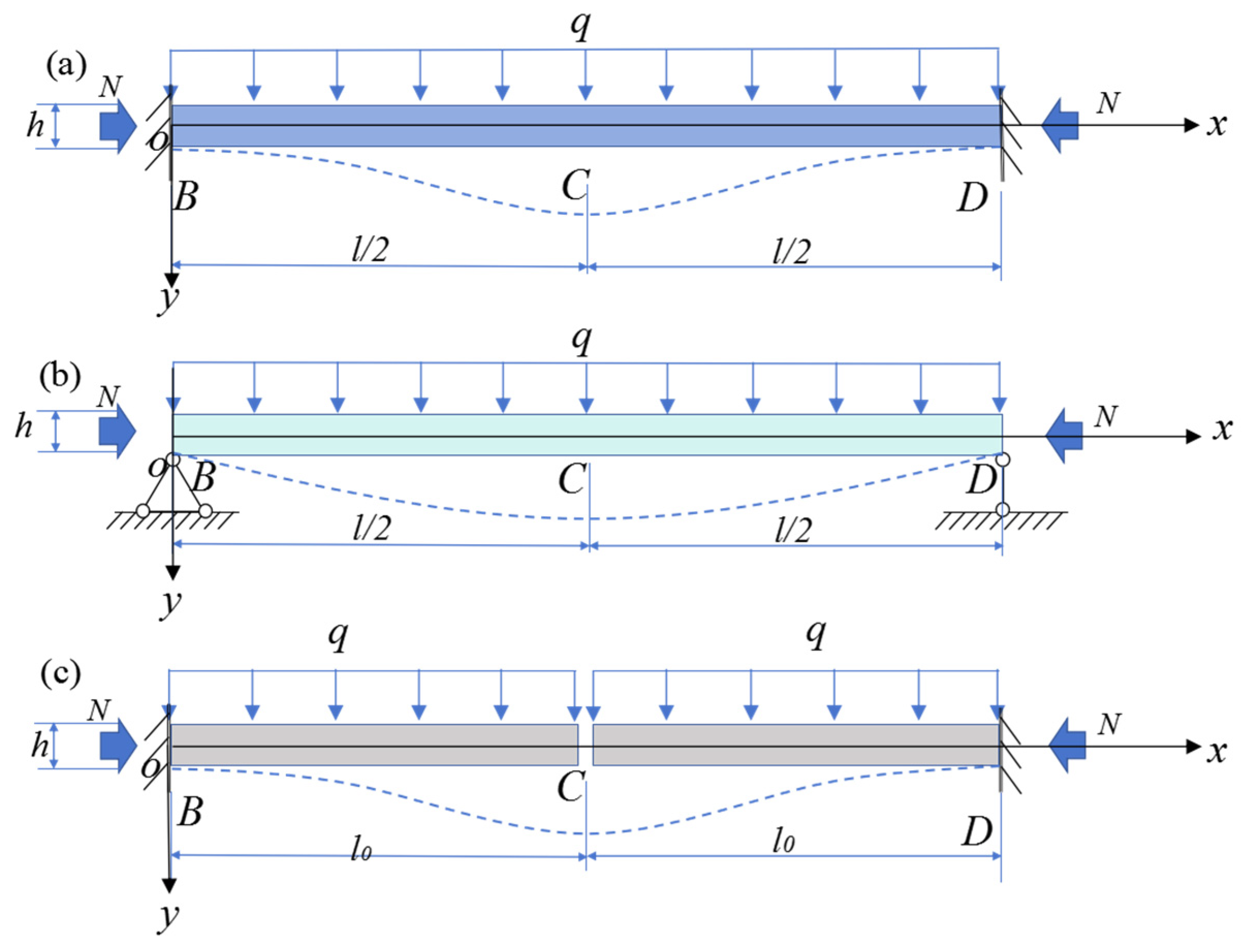
As shown in Figure 3, taking a unit width along the tunnel axis, considering the coupled action of stratum self-weight and horizontal principal stress, a mechanical analysis model is established. The interlayer bonding strength of gentle-dipping bedded rock mass in the vault is relatively low, and after tunnel excavation, the vault overlying rock loses the support of the lower rock mass and is prone to falling off risk. For the simplification of the mechanical model of the vault bedded rock mass, it is necessary to analyze the combination of stratum integrity and geological condition differences. Based on the integrity of vault strata, boundary constraint conditions and structural transformation characteristics, the separated strata can be simplified into three types of mechanical models:
Fixed-end beam model: Suitable for scenarios with good stratum integrity and effective consolidation constraints provided by side wall surrounding rock, which can significantly limit flexural deformation with small bending moment and deformation.
Simply supported beam model: Suitable for scenarios with invalid side wall constraints and only vertical support provided at stratum ends, with concentrated mid-span tensile stress and prone to bending fracturing.
Cantilever beam model: Suitable for residual strata after excavation cutting or local caving, with only one end consolidated, concentrated bending moment and deformation at the free end, and the highest instability risk.
The fracturing mechanical mechanism of bedded rock mass in the tunnel vault is analyzed in detail through single beam and composite beam models below.

4.1. Single Beam Model

If the vault horizontal strata are completely separated, considering the single beam mode as shown in Figure 4, assume that the length, width and height of the fixed-end beam and simply supported beam are l , b , h respectively, and the length, width and height of the cantilever beam are l 0 , b , h respectively. The bending stiffness of each beam is W = b h 2 6 , and the moment of inertia of each beam is I = b h 3 12 . The length of the spandrel cantilever beam can be considered as the average length l 0 = l 4 or the maximum length l 0 = l 2 . The equivalent uniform linear load of the vault stratum self-weight is q 1 = γ b h . The horizontal compressive stress at the vault tunnel wall after tunnel excavation is considered as the secondary stress field circumferential stress σ q 3 = σ θ of Formulas (4) and (5). The equivalent uniform load q 2 of the vault stratum settlement deformation u r after tunnel excavation needs to be converted according to the equivalent flexural deformation of the beam. The stress on the beam is the result of the coupled action of q 1 , q 2 and q 3 .
After the tunnel excavation is completed, the deformation of the tunnel wall can be calculated. The tunnel stratum is considered as a beam structure, and the excavation unloading is equivalent to a uniform load q 2 acting on the beam surface. The flexural deformation ω produced by the beam structure under uniform loading is equal to the deformation u r produced by tunnel excavation unloading, that is, u r = ω , then the equivalent uniform load q 2 can be calculated.
(1) Cantilever beam.
The end deflection of the cantilever beam under uniform load is ω = q 2 l 0 4 8 E I = u r 3 , then the equivalent uniform load q 2 is:
q 2 = 8 I l 0 4 U
where, U = γ H a 1 + μ 2 1 u + λ 2 u 1 .
(2) Fixed-end beam.
The mid-span deflection of the fixed-end beam under uniform load is ω = q 2 l 4 384 E I = u r 3 , then the equivalent uniform load q 2 is:
q 2 = 384 I l 4 U
(3) Simply supported beam.
The mid-span deflection of the simply supported beam under uniform load is ω = 5 q 2 l 4 384 E I = u r 3 , then the equivalent uniform load q 2 is:
q 2 = 384 I 5 L 4 U

4.1.1. Cantilever Beam

The fixed-end negative bending moment under the vertical self-weight uniform load q 1 is M = q 1 l 0 2 2 , and the fixed-end stress is:
σ q 1 = M W = 3 q 1 l 0 2 b h 2 = 3 γ l 0 2 h
The fixed-end stress under the deformation equivalent uniform load q 2 is:
σ q 2 = 3 q 2 l 0 2 b h 2 = 2 h l 0 2 U
The total stress at the end of the cantilever beam is:
σ q = σ q 1 + σ q 2 σ q 3
When considering the average length l 0 = l 4 , the total stress is:
σ q = 3 γ l 2 16 h + 32 h l 2 U σ q 3
When considering the average length l 0 = l 2 , the total stress is:
σ q = 3 γ l 2 4 h + 8 h l 2 U σ q 3

4.1.2. Fixed-End Beam

The fixed-end negative bending moment under the vertical self-weight uniform load q 1 is M = q 1 l 2 12 , and the mid-span bending moment is M = q 1 l 2 24 , then the fixed-end stress is:
σ q 11 = q 1 l 2 2 b h 2 = γ l 2 2 h
The mid-span stress is:
σ q 12 = q 1 l 2 4 b h 2 = γ l 2 4 h
The fixed-end stress under the deformation equivalent uniform load q 2 is:
σ q 21 = q 2 l 2 2 b h 2 = 16 h l 2 U
The mid-span stress is:
σ q 22 = q 2 l 2 4 b h 2 = 8 h l 2 U
The total stress at the end of the fixed-end beam is:
σ q = σ q 11 + σ q 21 σ q 3
The total mid-span stress of the fixed-end beam is:
σ q = σ q 12 + σ q 22 σ q 3

4.1.3. Simply Supported Beam

The mid-span bending moment under the vertical self-weight uniform load q 1 is M = q 1 l 2 8 , and the mid-span tensile stress is:
σ q 1 = 3 q 1 l 2 4 b h 2 = 3 γ l 2 4 h
The mid-span stress under the deformation equivalent uniform load q 2 is:
σ q 2 = 3 q 2 l 2 4 b h 2 = 24 h 5 L 2 U
The total mid-span stress of the simply supported beam is:
σ q = σ q 1 + σ q 2 σ q 3

4.2. Composite Beam Model

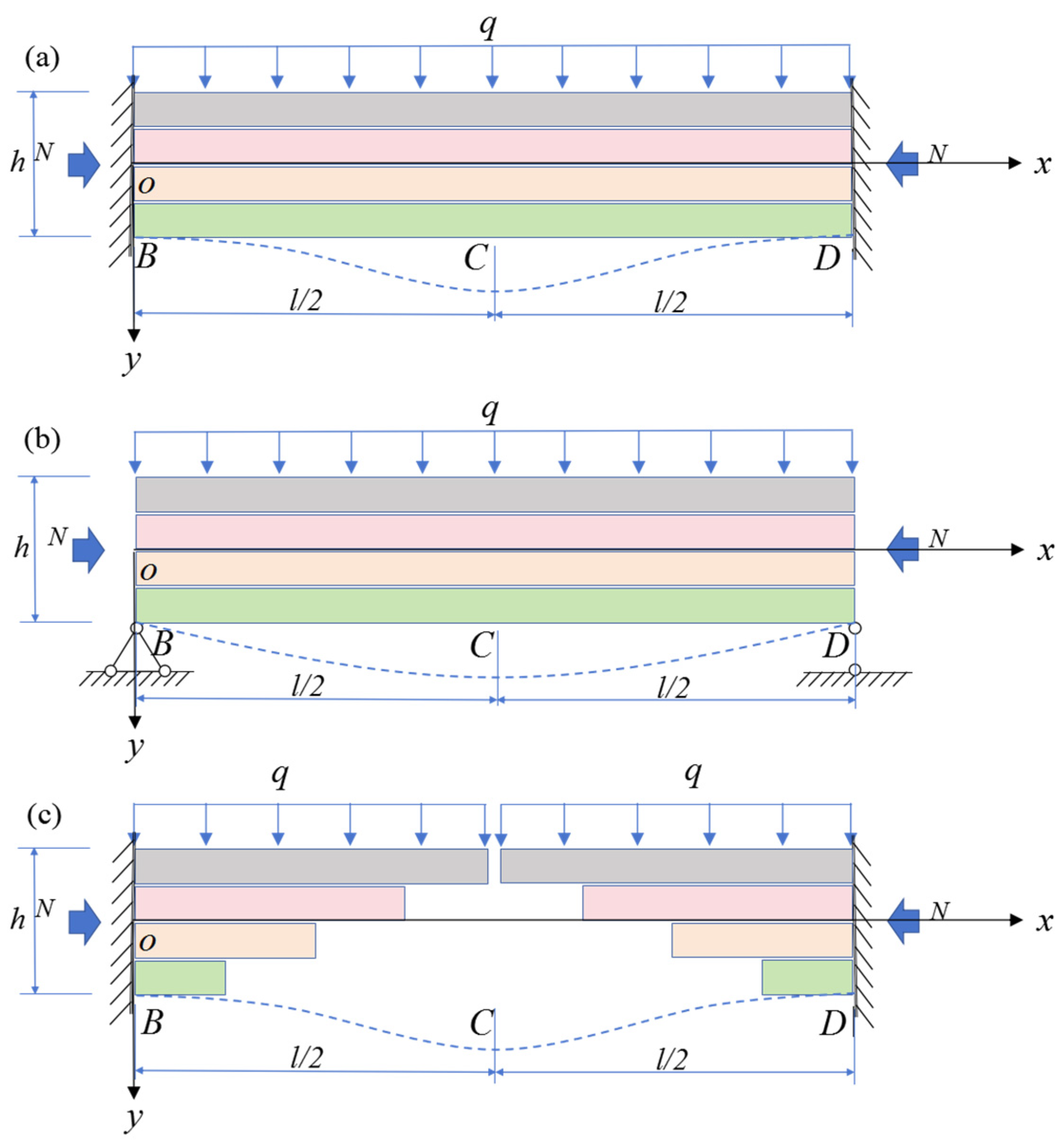
If the interlayer fractures of the vault composite strata are partially separated under the combined action of self-weight load, deformation load and horizontal stress, the interaction between stratum interfaces needs to be considered, and the multi-layer composite beam model shown in Figure 5 should be adopted.
Assume that the composite beam has n layers, the total stratum thickness is h , the length, width and height of the fixed-end beam and simply supported beam are l , b , h i respectively, and the length, width and height of the cantilever beam are l 0 , b , h i respectively, where h i is the thickness of the i-th layer in the composite beam. The moment of inertia of any layer i of the composite beam is I i = b h i 3 12 , and the bending modulus is W i = k b h i 2 6 , where k is the stratification coefficient of the composite beam [30], which can be taken as 0.65 when the number of layers i is not less than 4, and 0.7, 0.75 and 1.0 when the number of layers i is 3, 2 and 1 respectively.
After tunnel excavation, the deformation field of the surrounding rock can be calculated according to Formulas (6)–(8). The tunnel stratum is considered as a beam structure, and the excavation unloading is equivalent to a uniform load q 2 acting on the beam surface. The flexural deformation ω produced by the beam structure under uniform loading is equal to the deformation u r produced by tunnel excavation unloading, that is, u r = ω , then the equivalent uniform load q 2 can be calculated.
(1) Cantilever beam.
The end deflection of the cantilever beam under uniform load is ω = q 2 l 0 4 8 E I = u r 3 , then the equivalent uniform load q 2 i is
q 2 i = 2 b h i 3 3 l 0 4 U
(2) Fixed-end beam.
The mid-span deflection of the fixed-end beam under uniform load is ω = q 2 l 4 384 E I = u r 2 , then the equivalent uniform load q 2 i is
q 2 i = 16 b h i 3 l 4 U 0
where, U 0 = γ H 1 + μ 1 + λ a 2 r λ 1 a 4 r 3 + 1 u 4 a 2 r .
(3) Simply supported beam.
The mid-span deflection of the fixed-end beam under uniform load is ω = 5 q 2 l 4 384 E I = u r 2 , then the equivalent uniform load q 2 i is
q 2 i = 16 b h i 3 5 L 4 U 0

4.2.1. Cantilever Beam

There are n layers of layered cantilever beams in the near-triangular area of the spandrel, the closer to the vault, the longer of the length of the i -th layer from bottom to top. The beam length l i ranges from l 2 n ~ l 2 with linear change, the average length l i = l 4 , and the actual length of the i -th layer is l i = l i 2 n . The cantilever beam at the vault is subjected to the combined action of vertical uniform loads q 1 , q 2 and horizontal load q 3 . Under uniformly distributed vertical self-weight loads q 1 i = γ b h i , the fixed-end moment of the i-th layer is M q 1 i = q 1 i 2 l i 2 n 2 . Based on the deformation characteristics of the arch shoulder after cavern excavation, the vertical deformation at the beam ends is assumed to vary linearly, U i = i n U . Under uniformly distributed vertical deformation loads q 2 i = 2 b h i 3 3 l i 4 U i , the fixed-end moment of the i-th layer is M q 2 i = q 2 i 2 l i 2 n 2 . According to the circumferential stress Formula (4) for the tunnel surrounding rock, the horizontal stress at the beam ends can thus be approximated, σ q 3 = cos θ σ θ .
The maximum fixed-end stress is:
σ m a x = M q 1 i W i + M q 2 i W i σ q 3 = 3 γ l i 2 k h i + 2 h i k l i 2 i n U σ q 3
If the end stress σ m a x is greater than the tensile strength σ t of the rock mass, the stratum undergoes fracture failure.
(1)
When there is only n = 1 layer of vault strata, the above Formula (46) can be simplified as:
σ m a x = 3 γ l 2 4 h 1 + 8 h 1 l 2 U σ q 3
The above formula is the same as the mid-span stress expression (33) of the single beam model.
(2)
When there are n = 2 layers, k = 0.75 , the maximum end tensile stress is:
σ m a x 2 = 3 γ l 2 4 k h 2 + 8 h 2 k l 2 U σ q 3
σ m a x 1 = 3 γ l 2 16 k h 1 + 16 h 1 k l 2 U σ q 3
(3)
When n 4 layers, k = 0.65 , the maximum end tensile stress is:
σ m a x n = 3 γ k h n l 2 2 + 4 l 2 2 h n k U σ q 3
σ m a x 3 = 3 γ k h 3 3 l 2 n 2 + 4 n 3 L 2 2 h 3 k U σ q 3
σ m a x 2 = 3 γ k h 2 l n 2 + 2 n l 2 2 h 2 k U σ q 3
σ m a x 1 = 3 γ k h 1 l 2 n 2 + 4 n l 2 2 h 1 k U σ q 3

4.2.2. Fixed-End Beam

The fixed-end beam at the vault is subjected to the combined action of vertical uniform loads q 1 , q 2 and horizontal load q 3 . Under the vertical self-weight uniform load q 1 i = γ b h i , the mid-span bending moment is M q 1 i = q 1 i l 2 24 , and the end bending moment is q 1 i l 2 12 . Under the vertical deformation uniform load q 2 i , the mid-span bending moment is M q 2 i = q 2 i l 2 24 , and the end bending moment is q 2 i l 2 12 . Under the horizontal axial load q 3 i , the mid-span axial stress is:
σ θ 1 = 1 2 γ H 1 + λ 1 + a 2 r 2 1 λ 1 + 3 a 4 r 4
The mid-span axial stress of the vault tunnel wall is ( r = a ):
σ θ 2 = γ H 3 λ 1
where H is the burial depth at the bottom of the i-th stratum.
Then the maximum mid-span stress is:
σ m a x = γ l 2 4 k h i + 8 h i k l 2 U σ θ 2
The maximum end stress is:
σ m a x = γ l 2 2 k h i + 8 h i k l 2 U 0 σ θ 1
If the mid-span or end stress σ m a x of the fixed-end beam is greater than the tensile strength σ t of the rock mass, the stratum undergoes fracture failure.
When there is only n = 1 layer of vault strata, the above formula is simplified as:
The maximum mid-span stress is:
σ m a x = γ l 2 4 h 1 + 8 h 1 l 2 U σ θ 2
The maximum end stress is:
σ m a x = γ l 2 2 h 1 + 16 h 1 l 2 U σ θ 1
The above formula is the same as the mid-span stress expression (38) and (39) of the single beam model.
When there are n = 2 layers, k = 0.75 , the maximum tensile stress at the bottom of the mid-span is
σ m a x = γ l 2 4 k h 1 + 8 h 1 k l 2 U σ θ 2
The maximum tensile stress at the top of the end is:
σ m a x = γ l 2 2 k h 2 + 8 h 2 k l 2 U 2 σ θ 1
where, U 2 = γ H 1 + μ 1 + λ a 2 a + h 1 λ 1 a 4 a + h 1 3 + 1 u 4 a 2 a + h 1 .
When n 4 layers, k = 0.65 , the maximum tensile stress at the bottom of the mid-span is the same as expression (60), and the maximum tensile stress at the top of the end is:
σ m a x = γ l 2 2 k h n + 8 h n k l 2 U n σ θ 1
where, U n = γ H 1 + μ 1 + λ a 2 a + h h n λ 1 a 4 a + h h n 3 + 1 u 4 a 2 a + h h n , h n is the thickness of the n-th layer beam, and h is the total thickness of the composite beam.

4.2.3. Simply Supported Beam

The simply supported beam at the vault is subjected to the combined action of vertical uniform loads q 1 , q 2 and horizontal load q 3 . Under the vertical self-weight uniform load q 1 i = γ b h i , the mid-span bending moment is M q 1 i = q 1 i l 2 8 ; under the vertical deformation uniform load q 2 i , the mid-span bending moment is M q 2 i = q 2 i l 2 8 ; under the horizontal axial load q 3 i , the mid-span axial stress is σ θ 2 .
Then the maximum mid-span tensile stress is:
σ m a x = 3 γ l 2 4 k h i + 24 h i 5 k l 2 U σ θ 2
If the mid-span stress σ m a x is greater than the tensile strength σ t of the rock mass, the stratum undergoes fracture failure.
When there is only n = 1 layer of vault strata, the above formula is simplified as:
σ m a x = 3 γ l 2 4 h 1 + 24 h 1 5 L 2 U σ θ 2
The above formula is the same as the mid-span stress expression (42) of the single beam model.
When there are n = 2 layers, k = 0.75 , the maximum tensile stress at the bottom is:
σ m a x = 3 γ l 2 4 k h 1 + 24 h 1 5 k l 2 U σ θ 2
When n 4 layers, k = 0.65 , the maximum tensile stress expression at the bottom is the same as above expression (65).

5. Discussion and Application

5.1. Vault Stratum Separation Criterion

Vault stratum separation is jointly controlled by the lateral pressure coefficient λ , tunnel diameter a , stratum thickness t , tensile strength σ t and confining pressure P = γ H . By transforming the discriminant into a function of the lateral pressure coefficient λ , the criterion selection rules and cracking judgment conditions in different R = a 2 a + t 2 intervals are obtained, which can realize the quantitative discrimination of stratum separation status.
(1) Discrimination condition.
The vault stratum separation discriminant Equation (19) can be written as the product of two linear functions about λ , f λ = f λ 1 f λ 2 ,
f λ 1 = 3 R 2 + 3 R + 3 λ + 3 R 2 R + 1 = a λ + b
f λ 2 = 3 R 2 + 5 R + 1 λ + 3 R 2 7 R + 3 = c λ + d
By analyzing the coefficients a, b, c, and d in the above equation, the selection table for separation initiation discrimination criteria shown in Table 1 can be established. Given the fundamental input parameters, the critical separation initiation discrimination criteria can also be directly obtained via table lookup.
(2) Discussion on criterion ①
The vault stratum separation criterion ① Equation (20) can be written as the product of two linear functions about λ , namely f λ = f λ 3 f λ 4 :
f λ 3 = 3 R 2 + 3 R λ + 3 R 2 5 R + 2 σ t P + 2 = a λ + b
f λ 4 = 3 R 2 + R + 2 λ + 3 R 2 + R + 2 σ t P = c λ + d
By analyzing the coefficients a, b, c and d in the foregoing equation, Table 2 summarizing the criteria ① separation initiation can be constructed. When the fundamental governing parameters are known, table lookup can be directly adopted to judge whether separation initiation occurs in rock strata.
(3) Discussion on criterion ②
Separation criterion ② for vault strata Equation (21) can be expressed as a quadratic function of the lateral pressure coefficient λ :
f λ = 3 R 2 R + 1 λ 3 R 2 3 R + 1 2 + 8 σ t P 1 + 2 R λ + 1 2 R
The foregoing equation is relatively straightforward. The separation initiation state of rock strata can be directly determined by substituting known parameters into the equation. Separation initiation takes place if f λ < 0 , whereas no separation initiation occurs otherwise.

5.2. Comparative Verification

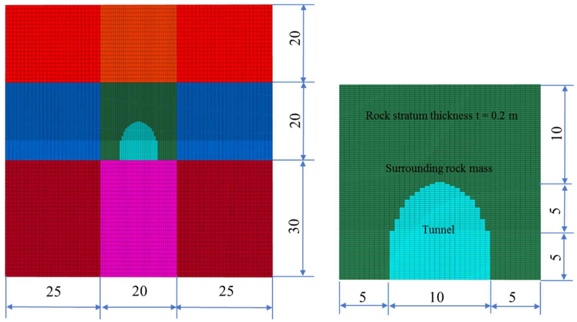
A city-gate-shaped tunnel is constructed for finite difference numerical simulation via FLAC3D, as illustrated in Figure 6. The tunnel has a span of 10 m and a height of 10 m, and the influence range of surrounding rock in the numerical model is taken as three times the tunnel width. Interfaces are embedded between rock strata above the tunnel floor to reproduce the mechanical behaviors of stratified rock mass. The overburden depth of the cavern is set to 300 m, and the lateral pressure coefficient is 0.9. The average stratum thickness of rock layers is 0.2 m, with each mesh element thickness assigned as 0.1 m. Other rock mass parameters are listed as follows: unit weight is 25 kN/m3, deformation modulus is 5.0 GPa, Poisson’s ratio = 0.30, cohesion = 0.5 MPa, internal friction angle = 35°, and tensile strength = 0.1 MPa. For interlayer interfaces, the cohesion is 0.05 MPa, the internal friction angle is 13°, the tensile strength is 0.01 MPa, and the normal stiffness and shear stiffness are 3.0 GPa and 1.0 GPa, respectively.
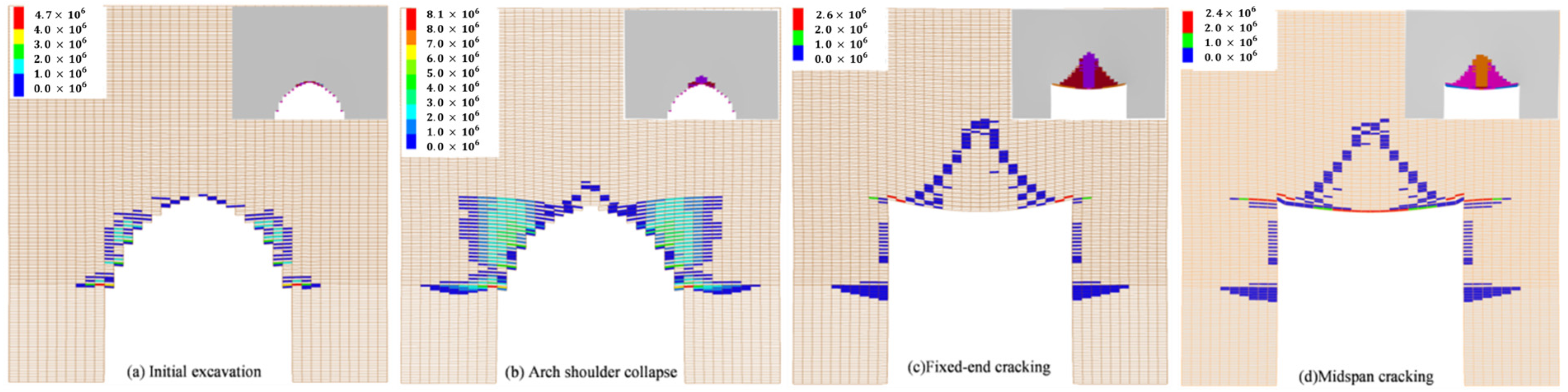
The evolution process of delamination of roof rock strata is presented in Figure 7. Rock stratum separation takes place once the interface strength exceeds the interlayer tensile strength. Rock fracture occurs when the major principal stress of rock elements surpasses the tensile strength of intact rock. After cavern excavation, the surrounding rock undergoes convergent deformation, and the roof rock strata bend toward the excavation free surface. Rock layers adjacent to the free surface gradually separate and crack; arc-shaped rock blocks near the arch foot continuously collapse, ultimately forming an approximate flat-topped structure. With further deformation of the roof strata, the quantity of separated rock layers rises and the horizontal separation length expands continuously.
Based on the relevant theoretical derivations presented above, the overlying rock load fails to satisfy the discrimination criterion in Equation (19). So Criterion ② of Equation (21) is adopted. Since the separation condition is fulfilled, separation inevitably occurs at the lowermost rock stratum. Further calculations yield a total separation thickness of 5.6 m, indicating that interlayer separation takes place across 28 horizontal rock strata.
The comparative results between the numerical simulation method and the theoretical analytical method are summarized in Table 3. Interlayer separation is observed in the roof rock strata in all numerical cases. The maximum rock separation thickness at the vault predicted by the theoretical method and numerical method is 5.60 m and 5.20 m, respectively. The relative error of separation thickness derived from the two approaches is less than 10%, and the stress values at key characteristic sections show favorable agreement with the theoretical predictions proposed in this study.
For the composite beam model and numerical simulation, as shown in Table 3, the stresses at critical locations are listed as follows: 4.59 MPa (theoretical)/4.66 MPa (numerical) at the cantilever beam end, 2.52 MPa/2.59 MPa at the fixed-end beam end, and 2.42 MPa/2.38 MPa at the midspan of the simply supported beam. All these stress magnitudes exceed the tensile strength of the rock mass, which implies the potential for tensile cracking within the vault strata.

5.3. Case Application

A large-scale underground cavern in western China is taken as an engineering case. The cavern measures approximately 28.5 m × 56 m with a buried depth of about 400 m. Strata are gently dipping sandstone interbedded with sandy mudstone, with dip angles ranging from 10° to 20°. Interlayer fractures and steeply dipping fractures are well developed, resulting in high vault instability risk.
Key parameters: Span l = 30 m , Unit weight γ   =   27   kN / m 3 , Overburden depth H = 400 m , Interlayer tensile strength σ t = 0.1 MPa, Lateral pressure coefficient λ = 1.05, Poisson’s ratio u = 0.25, Stratum thickness h i = 0.1 ~ 2.0 m (average 1.0 m).
Support design: Systematic rock bolts, Φ32/28, L = 9 m/6 m, spaced 1.5 m × 1.5 m; Wire mesh, Φ8@15 cm × 15 cm; Shotcrete, 20 cm thick C25; Prestressed anchor cables, T = 1500 kN, L = 20 m; Through going anchor cables, T = 1500 kN, L = 35 m (5 rows at vault and spandrel).
Insufficient flexural capacity is the core cause of failure in gently dipping bedded rock. Tensile failure occurs once stratum tensile stress exceeds tensile strength, with the failure mode governed by stratum dip angle, stress state, and interface mechanical properties. The vault rock mass in the project is typical gently dipping medium thickness bedded rock with low interlayer bonding strength, cut by multiple sets of steeply dipping structural planes, and fracture spacing ranges from 0.1 m to 2.0 m, resulting in poor structural integrity. After excavation of the large span cavern, the vault surrounding rock is prone to peeling, spalling, and collapse along bedding planes under the combined effects of unloading and overburden load.
Deformation evolution of vault rock directly controls the overall stability of the cavern. Excavation unloading causes the overlying rock to lose lower support, with loads transferred mainly to the vault and side walls. Although an arched structure is adopted, the large span causes strata to form an equivalent cantilever beam, which undergoes significant flexural deformation under uniform load and cannot self-stabilize. Superimposed horizontal tectonic stress further intensifies inward deformation of strata and triggers peeling of surface strata. With the propagation of separation, strata fracture and buckle; failure of the first layer triggers stress release and redistribution, loads transfer upward, and progressive collapse occurs until a limit equilibrium arch forms. In addition, the rock mass is precut by interlayer and steeply dipping fractures before excavation, providing inherent conditions for cracking, and excavation disturbance further exacerbates buckling, separation, and block instability.
The cavern features well developed fractures and a large span, and vault rock is cut by both gently dipping bedding and steeply dipping structural planes, providing inherent conditions for cracking. Influenced by steeply dipping fractures, the embedment of outer spandrel strata is greatly weakened, so the support constraint assumptions of traditional fixed end and cantilever beam models are no longer applicable. After on site excavation, spandrels generally show spalling and collapse, forming an enlarged mushroom shaped flat oblique vault, which is consistent with theoretical predictions.
(1) Initiation Judgment.
For tunnel radius a = 15.0   m and stratum thickness t = 1.0 m: R = a 2 a + t 2 = 0.88 . The separation discriminant f λ = 2.39 > 0 , so criterion ② (Equation (21)) is applied. For 0.566 < R = 0.88 < 1 , critical values are λ 1 = 0.276   and   λ 2 = 0.273 . Since λ 1 < λ = 1.05 , criterion ② yields f λ = 3.38 < 0 , so vault strata inevitably separate. Given fixed R and λ , separation can be prevented only if σ t P > 0.2 (i.e., σ t > 2.16   M P a ). Given fixed σ t and P , separation can be prevented only if R < 0.17 (i.e., t > 21   m ). Thus anchor cables for reinforcement should be at least 21 m long. The designed ordinary prestressed cables are only 20 m, so the additional 35 m through going cables at the vault are strongly justified [31,32].
(2) Single Beam Model.
From Equation (33), the end stress of the cantilever beam is 19.98 MPa, indicating that the cantilever beams at the spandrel will definitely undergo tensile fracture failure. According to Equations (38) and (39), the end stress of the fixed-end beam is −7.56 MPa, and the total mid-span stress of the fixed-end beam is −15.39 MPa, meaning that the vault fixed-end beams will not crack. From Equation (42), the total mid-span stress of the simply supported beam is −3.94 MPa, so the vault simply supported beams remain stable without cracking.
(3) Composite Cantilever Beam.
For strata at the spandrel modeled as composite cantilever beams with a layer number n 4 , Equations (50)–(53) shows that under basic conditions, the beam end stress reaches 12.41 MPa, and brittle fracture failure is inevitable. The maximum tensile stress σ m a x at the cantilever beam end—and thus the cracking risk—increases with smaller rise–span ratio of the cavern, thinner layer thickness h i , larger tunnel diameter a , larger lateral pressure coefficient λ , greater burial depth H .
(4) Composite Fixed-End Beam.
For vault strata simulated as composite fixed-end beams with n 4 , Equations (60)–(62) indicate that under basic conditions, the beam end stress is 7.56 MPa and the mid-span bottom stress is −11.17 MPa, suggesting potential end cracking. The maximum tensile stress σ m a x at the fixed-end beam end—and hence cracking susceptibility at both ends and mid-span—increases with: smaller total stratum thickness h ; thinner top-layer thickness h n or bottom-layer thickness h 1 ; larger tunnel diameter a or span l ; smaller lateral pressure coefficient λ ; larger Poisson’s ratio u ; smaller burial depth H . Thresholds for tensile-stress-free conditions (single-factor analysis): No tensile stress at beam ends when H > 750   m ; No tensile stress at the vault bottom when h 1 > 0.43   m , l < 45   m , λ > 0.72 , H > 200   m .
(5) Composite Simply Supported Beam.
For vault strata treated as composite simply supported beams with n 4 , Equations (63)–(65) shows that under basic conditions, the mid-span bottom stress is 6.44 MPa, implying possible mid-span tensile failure. The maximum tensile stress σ m a x increases with: thinner bottom-layer thickness h 1 ; larger tunnel diameter a or span l ; smaller lateral pressure coefficient λ ; larger Poisson’s ratio u ; smaller burial depth H . Thresholds for tensile-stress-free conditions at the vault bottom (single-factor analysis): h 1 > 1.3   m , l < 28   m , λ > 1.2 , H > 500   m .
For cavern-wall strata in vault composite simply supported beams, mechanical performance can be improved only by increasing the effective thickness via external support. After reinforcement with systematic surface rock bolts (Φ32/28, L = 9 m/6 m), the effective thickness of cavern-wall strata is taken as h 1 = 6   m . The maximum mid-span stress of the simply supported beam becomes −8.82 MPa, demonstrating a significant reinforcement effect [33].

5.4. Applicability Analysis

Cracking failure in brittle rock materials fundamentally occurs when the applied stress exceeds the inherent tensile strength of the rock mass, which resembles the Brazilian splitting test [34]. The propagation direction of cracking damage runs parallel to the principal stress direction [29]. Combined with the stress distribution characteristics induced by cavern excavation, this study derives Criterion Formulas (19)–(21) for stratification separation of tunnel surrounding rock under non-axisymmetric external loads. The proposed formula is applicable not only to circumferential layered splitting on the excavation boundary of homogeneous rock masses and interlayer separation in horizontally bedded rock masses, but also extends to layered fracturing associated with rockbursts in hard rock formations. Given the tunnel diameter, lateral pressure coefficient, overburden depth, unit weight of surrounding rock, tensile strength of host rock, and bed thickness, this criterion can quantitatively judge the occurrence of rock stratification separation and calculate the thickness of separated rock layers. For horizontal bedded rock masses, interlayers exhibit low tensile strength, such that stratification separation initiates under relatively low horizontal loading.
Equations (1)–(3) describes the secondary stress field developed in surrounding rock following underground cavern excavation. Any infinitesimal element within the surrounding rock bears radial and circumferential normal stresses at its centroid, together with shear stresses acting on its boundaries [35]. At the crown of the tunnel, the major principal stress corresponds to the circumferential stress component, with zero shear stress prevailing at this location. In most underground caverns, excavation span far exceeds the thickness of individual horizontal strata. Accordingly, the curved crown rock layers of large-span caverns with a low rise-span ratio can be simplified as straight beam structures for mechanical analysis [30].
The beam theoretical framework established in this research incorporates the coupled effects of three deformation or stress components: vertical deformation induced by self-weight of rock strata, displacement triggered by cavern excavation, and additional vertical deformation arising from horizontal loads. For intact rock layers without stratification separation, a layered coefficient [30] for composite beams is introduced to account for the comprehensive reduction effect originating from mechanical interactions between stacked rock beams. In contrast, interlayer interactions are neglected for fully separated rock strata.
Excavation-induced deformation of underground caverns in homogeneous strata is primarily governed by the rock deformation modulus. By contrast, horizontally bedded strata with prominent structural discontinuities are additionally controlled by interlayer structural planes and the flexural rigidity of individual rock beds. Coal mining-induced caving zones featuring distinct three-zone distribution [12,13] serve as a representative engineering case of such structural control. This paper focuses exclusively on stress-driven fracturing failure mechanisms; further follow-up research will investigate the deformation evolution characteristics of layered rock masses post-excavation.
Distinct from conventional beam theories widely adopted in previous mining research [21], the theoretical framework established in this paper targets the vault failure behaviours of underground caverns excavated within nearly horizontal stratified rock masses and possesses prominent analytical advantages. Unlike traditional solutions that only evaluate rock beam cracking, the proposed approach first identifies the interlayer separation state of arch vault strata according to excavation-induced secondary stress fields, quantitatively predicts the maximum separation thickness of layered rock masses, and systematically clarifies the influential scope of surrounding rock at the vault from the fundamental perspective of secondary stress distribution. Classical analytical models simplify interlayer mechanical interactions as pure shear contact under the premise of full bonding between adjacent rock strata; however, engineering and numerical observations demonstrate that evident interlayer voids form in vault strata after cavern excavation, exhibiting deformation characteristics analogous to the classic three-zone distribution law observed in underground coal mining. This phenomenon fully illustrates that rock layers cannot maintain complete contact after excavation, and interlayer separation inevitably emerges within the vault stratified rock mass. Theoretically, interlayer mechanical coupling can be ignored if thorough separation exists between vault strata, yet practical engineering conditions rarely satisfy this ideal state. In most cases, vault rock masses undergo partial separation with an axisymmetric distribution feature, where the length of separated interfaces increases gradually towards the excavation free face and expands continuously with the extension of excavation time.
For such partially separated layered strata, interlayer interaction effects cannot be omitted during mechanical analysis, which highlights the necessity of introducing the composite beam stratification coefficient k proposed in existing literature [30]. This coefficient holds a well-defined physical meaning, which quantitatively characterises the reduction degree of flexural stiffness of multi-layer composite beam structures relative to intact single rock beams. Although the stratification coefficient is currently obtained through empirical summarisation without mature explicit theoretical formulas, it still carries reliable practical engineering applicability and reference value when alternative analytical methods are unavailable.
More importantly, this study reveals a unique symmetric partial separation evolution law of vault strata: interlayer separation originates from the uppermost rock layer near the tunnel midspan and then expands bidirectionally towards both arch shoulders and upward into deeper strata, forming a special state where the central vault region develops interlayer separation while rock layers on both sides remain closely contacted. This critical discovery indicates that the two extreme assumptions of full interlayer contact and complete interlayer separation are both inappropriate when constructing composite beam models for stratified vault rock masses. Additionally, the value of stratification coefficient k is jointly restricted by multiple geological and structural factors, including single stratum thickness, interlayer contact condition, interlayer separation degree, the total number of separated rock layers and the overall separation range. Given the complex multi-factor coupling effect governing this coefficient, establishing its precise quantitative functional relationship with the above key parameters will serve as the core research direction of our follow-up work.

6. Conclusions

This study focuses on the vault strata of underground caverns in gently dipping bedded rock masses. Using theoretical analysis, mechanical modeling, analytical derivation, and engineering validation, we systematically reveal the evolutionary process, mechanical mechanism, and controlling factors of separation and fracturing in vault strata induced by excavation unloading. A Griffith-based crack initiation criterion for surrounding rock under non-axisymmetric loading and a beam-stress calculation model for layered rock masses are established. The spatiotemporal evolution and key governing parameters of progressive vault failure are quantified. Verified by a field case, the results provide a robust theoretical foundation and technical support for stability assessment and support design in analogous underground engineering projects. The main conclusions are as follows:
(1)
The failure of vault strata displays distinct spatiotemporal evolution and zonal characteristics. Excavation triggers radial unloading and tangential tensile–shear stress concentration, with interlayer separation occurring prior to through-bed fracturing. Separation propagates upward in a gradient-attenuating manner, forming a lower intense separation zone, a middle transition zone, and an upper closed zone. The vault strata undergo cyclic structural transformation: cantilever beam, fixed-end beam, simply supported beam, leading to stepped, upward-propagating failure and eventually forming a self-supporting limit equilibrium arch.
(2)
The fracture and collapse zone follows a three-stage evolution: expansion, peak, stabilization. From the early excavation stage to the mid-failure stage, separation and cracks expand rapidly, increasing the disturbed zone and collapse scale. The failure zone reaches its maximum height and span at the mid-stage. In the late stage, the stress arch carries overburden loads, constraints are enhanced, and the collapse zone converges toward the mid-span until stable. This behavior arises from the combined effects of stress relaxation and stress-arch self-balancing.
(3)
A Griffith crack initiation criterion for surrounding rock of circular caverns under non-axisymmetric loading is derived based on stress transformation in elasticity. It quantifies the coupling between principal stresses, tangential/radial/shear stresses, and tensile strength, enabling accurate prediction of interlayer separation and cracking under true in-situ stress conditions.
(4)
A complete mechanical framework for single and composite beams in layered strata is constructed. Vault strata are simplified into fixed-end, simply supported, and cantilever beam models, with corresponding stress formulas derived. Bending-stiffness correction factors are provided for various layer counts and thicknesses, allowing precise computation of the maximum tensile stress. Bending–tensile failure occurs when the calculated stress exceeds the tensile strength of the rock mass.
(5)
The key parameters controlling vault cracking and stability are identified. Cracking resistance is enhanced by a larger lateral pressure coefficient, thicker strata, smaller cavern span, greater burial depth, and higher rock tensile strength. Conversely, lower interlayer strength, larger span, and smaller lateral pressure coefficient favor tensile failure at the spandrel cantilever segments and vault mid-span.
(6)
The theoretical model is highly consistent with field observations and numerical simulation case and possesses strong engineering applicability. The relative error of separation thickness and stress values derived from the two approaches is less than 10%. Validation at a large underground cavern in western China shows that the separation criterion and stress calculations closely match on-site spalling, separation, cracking, and support performance. Support parameters including cable length, bolt spacing, and shotcrete thickness determined from theoretical results effectively control vault deformation and failure. The outcomes can be directly applied to stability analysis and support optimization for similar caverns in gently dipping bedded rock masses.

Author Contributions

Conceptualization, G.L. and N.L.; methodology, G.L., N.L. and K.W.; validation, K.W. and G.L.; formal analysis, G.L., Y.H. and Y.B.; investigation, K.W., Y.H. and G.L.; writing—original draft preparation, G.L. and Y.B.; writing—review and editing, G.L. and Y.B.; supervision, G.L. and N.L.; funding acquisition, G.L. All authors have read and agreed to the published version of the manuscript.

Funding

The authors would like to acknowledge the following financial supports: Project (52309144) supported by National Natural Science Foundation of China, Project (GZC20232139, 2024M762626) supported by China postdoctoral researchers funded planning and China Postdoctoral Science Foundation.

Institutional Review Board Statement

Not applicable.

Informed Consent Statement

Not applicable.

Data Availability Statement

The data used to support the findings of this study are available from the corresponding author upon request.

Acknowledgments

We would like to thank the anonymous reviewers for their time and effort devoted to improving the quality of this research. The financial support provided by this sponsor is greatly appreciated.

Conflicts of Interest

The authors declare no conflicts of interest.

References

  1. Zhang, Y.; Ding, X.; Huang, S.; Wu, Y.; He, J. Strength degradation of a natural thin-bedded rock mass subjected to water immersion and its impact on tunnel stability. Geomech. Eng. 2020, 21, 63–71. [Google Scholar] [CrossRef]
  2. Zhao, D.; He, Q.; Ji, Q.; Wang, F.; Tu, H.; Shen, Z. Similar model test of a mudstone-interbedded-sandstone-bedding rock tunnel. Tunn. Undergr. Space Technol. 2023, 140, 105299. [Google Scholar] [CrossRef] [Scilit]
  3. Do, N.A.; Dias, D.; Dinh, V.D.; Tran, T.T.; Dao, V.C.; Dao, V.D.; Nguyen, P.N. Behavior of noncircular tunnels excavated in stratified rock masses—Case of underground coal mines. J. Rock Mech. Geotech. Eng. 2019, 11, 99–110. [Google Scholar] [CrossRef] [Scilit]
  4. Yang, C.; Wang, T.; Chen, H. Theoretical and technological challenges of deep underground energy storage in China. Engineering 2023, 25, 168–181. [Google Scholar] [CrossRef] [Scilit]
  5. Fan, Q.-X.; Feng, X.T.; Zhou, Y.-Y.; Xu, D.-P. An enhanced equivalent continuum model for layered rock mass incorporating bedding structure and stress dependence. Int. J. Rock Mech. Min. Sci. 2017, 97, 75–98. [Google Scholar] [CrossRef] [Scilit]
  6. Fang, Z.; Zhang, C.; Xie, Q.; Liu, C.; Chen, H. Revisiting anisotropic rock strengths with an improved model considering angle offset and non-uniform scaling. Bull. Eng. Geol. Environ. 2026, 85, 271. [Google Scholar] [CrossRef] [Scilit]
  7. Xia, L.; Zeng, Y.W.; Luo, R.; Liu, W. Influence of bedding planes on the mechanical characteristics and fracture pattern of transversely isotropic rocks in direct shear tests. Shock Vib. 2018, 2018, 6479031. [Google Scholar] [CrossRef] [Scilit]
  8. Zou, W.B.; Yang, S.C.; Xu, J.M. Influence of the elastic dilatation of mining-induced unloading rock mass on the development of bed separation. Energies 2018, 11, 785. [Google Scholar] [CrossRef] [Scilit]
  9. Wu, J.; Cheng, G.; Jin, Z.; Han, Z.; Peng, F.; Jia, J. Characteristics and deformation mechanisms of neogene red-bed soft rock tunnel surrounding rock: Insights from field monitoring and experimental analysis. Buildings 2025, 15, 1820. [Google Scholar] [CrossRef] [Scilit]
  10. Li, A.; Liu, Y.; Dai, F.; Liu, K.; Wei, M. Continuum analysis of the structurally controlled displacements for large-scale underground caverns in bedded rock masses. Tunn. Undergr. Space Technol. 2020, 97, 103288. [Google Scholar] [CrossRef] [Scilit]
  11. Gao, Z.; Luo, J.J.; Wu, X.; Li, K. Deformation analysis of the rock surrounding a tunnel excavated through a cently dipping bed. Appl. Sci. 2022, 12, 1960. [Google Scholar] [CrossRef] [Scilit]
  12. Wang, Y.; Kong, D.; Wu, G.; Xiong, Y. Study on failure of roof overburden and high ground pressure control under deep repeated mining. Eng. Fail. Anal. 2026, 183, 110226. [Google Scholar] [CrossRef] [Scilit]
  13. Liu, Y.; Zhu, Q.; Wei, Q.; Yang, G.; Zhang, Y.; Hao, Q.; Jiang, D. Theoretical framework and reliability verification of the loaded three-zone structural model in coal mine overburden strata. Sci. Rep. 2025, 15, 35359. [Google Scholar] [CrossRef] [Scilit] [PubMed]
  14. Liu, X.; Chen, H.; Liu, K.; He, C. Model test and stress distribution law of unsymmetrical loading tunnel in bedding rock mass. Arab. J. Geosci. 2017, 10, 184. [Google Scholar] [CrossRef] [Scilit]
  15. Liu, X.; Zhang, S.; Wang, J.; Wei, P.; Yin, H.; Chen, J. Macro-mechanical property and microfracture evolution of layered rock mass: Effects of confining pressure and bedding direction. Appl. Sci. 2025, 15, 12178. [Google Scholar] [CrossRef] [Scilit]
  16. Liu, X.; Meng, Y.; Jing, H.; Liu, W.; Wan, C.; Cao, Y.; Yin, Q. Effects of bedding plane properties on mechanical, acoustic emission and micro failure characteristics of bedded rock mass. Bull. Eng. Geol. Environ. 2024, 83, 191. [Google Scholar] [CrossRef] [Scilit]
  17. Shu, X.; Zhu, Z.; Qu, S.; He, L.; Zeng, H.; Zhang, C.; Tian, Y. Anisotropic characteristics and deformation behaviors of layered rocks surrounding tunnel: A review. J. Rock Mech. Geotech. Eng. 2025, 17, 8198–8223. [Google Scholar] [CrossRef] [Scilit]
  18. Liu, P.; Wang, H.; Liu, Q.; Li, X.; Dong, Y.; Xie, X. FDEM numerical study on the large deformation mechanism of layered rock mass tunnel under excavation-unloading disturbance. Tunn. Undergr. Space Technol. 2025, 159, 106497. [Google Scholar] [CrossRef] [Scilit]
  19. Zheng, C.; Zhu, X.; Zhang, Z. Damage evolution of tunnel lining under creep action considering interlayer effect in gently inclined layered surrounding rock. Eng. Fail. Anal. 2024, 162, 108392. [Google Scholar] [CrossRef] [Scilit]
  20. Chen, J.; Liu, W.; Chen, L.; Luo, Y.; Li, Y.; Gao, H.; Zhong, D. Failure mechanisms and modes of tunnels in monoclinic and soft-hard interbedded rocks: A Case Study. KSCE J. Civ. Eng. 2020, 24, 1357–1373. [Google Scholar] [CrossRef] [Scilit]
  21. Chen, H.J.; Zuo, S.Y.; He, X. Mechanical model and experimental verification of horizontally layered rock beams for a tunnel roof with different bonding strengths between the layers. Int. J. Geomech. 2010, 25, 14. [Google Scholar] [CrossRef] [Scilit]
  22. Li, A.; Dai, F.; Xu, N.; Gu, G.; Hu, Z. Analysis of a complex flexural toppling failure of large underground caverns in layered rock masses. Rock Mech. Rock Eng. 2019, 52, 3157–3181. [Google Scholar] [CrossRef] [Scilit]
  23. Xiao, P.W.; Yang, X.G.; Li, B.; Zhou, X.; Sun, Y.; Ding, X.; Xu, N. Roof arch collapse of underground cavern in fractured rock mass: In situ monitoring and numerical modeling. J. Rock Mech. Geotech. Eng. 2025, 17, 2778–2792. [Google Scholar] [CrossRef] [Scilit]
  24. He, Y.; Han, L.; Zhang, H. Study of rock splitting failure based on griffith strength theory. Int. J. Rock Mech. Min. Sci. 2016, 83, 116–121. [Google Scholar] [CrossRef] [Scilit]
  25. Li, Y.; Gao, X.; Yang, J.; Bai, E. Quantitative 3-D investigation of faulting in deep mining using Mohr–Coulomb criterion and slip weakening law. Geomech. Geophys. Geo-Energy Geo-Resour. 2025, 11, 10. [Google Scholar] [CrossRef] [Scilit]
  26. Meng, Y.; Chen, H.; Jing, H.; Yu, L.; Zhuang, J.; Liu, X.; Zhang, C. An anisotropic damage constitutive model based on Hoek-Brown criterion and its application in tunnel engineering. Eur. J. Environ. Civ. Eng. 2025, 29, 1871–1894. [Google Scholar] [CrossRef] [Scilit]
  27. Lopez-Pamies, O.; Kamarei, F. When and where do large cracks grow? Griffith energy competition constrained by material strength. Extrem. Mech. Lett. 2025, 81, 102417. [Google Scholar] [CrossRef] [Scilit]
  28. Zhu, Q.-Z. A new rock strength criterion from microcracking mechanisms which provides theoretical evidence of hybrid failure. Rock Mech. Rock Eng. 2016, 50, 341–352. [Google Scholar] [CrossRef] [Scilit]
  29. Wang, S.; Tan, F.; You, M.; Jiao, Y.-Y.; Tu, F. Discrete element modeling of crack initiation stress of marble based on griffith’s strength theory. Adv. Civ. Eng. 2020, 2020, 8876661. [Google Scholar] [CrossRef] [Scilit]
  30. Pei, Q.Q.; Bai, Y.S.; Guo, Q.L.; Liu, H.; Chen, W. Study on the mechanical spalling damage mechanism of the layered flat roof in Beishiku Temple. Chin. J. Eng. Geol. 2024, 32, 2041–2054. [Google Scholar] [CrossRef]
  31. Zhu, W.X.; Jing, H.W.; Yang, L.J.; Pan, B.; Su, H. Strength and deformation behaviors of bedded rock mass under bolt reinforcement. Int. J. Min. Sci. Technol. 2018, 28, 54–60. [Google Scholar] [CrossRef] [Scilit]
  32. Zhang, Z.; Liu, Y.; Teng, J.; Zhang, H.; Chen, X. An investigation into bolt anchoring performance during tunnel construction in bedded rock mass. Appl. Sci. 2020, 10, 2329. [Google Scholar] [CrossRef] [Scilit]
  33. Chen, Y.; Teng, J.; Sadiq, R.A.B.; Zhang, K. Experimental study of bolt-anchoring mechanism for bedded rock mass. Int. J. Geomech. 2020, 20, 04020019. [Google Scholar] [CrossRef] [Scilit]
  34. Heng, Z.; Xu, T.; Konietzky, H.; Zhu, W.; Ranjith, P. New insights into the continuous-discontinuous failure characteristics of granite under Brazilian splitting test conditions using acousto-optic-mechanical (AOM) method. Int. J. Rock Mech. Min. Sci. 2025, 187, 106041. [Google Scholar] [CrossRef] [Scilit]
  35. Li, G.; Li, N.; Bai, Y.; Yang, M. A new elastic-plastic analytical solution of circular tunnel under non-axisymmetric conditions. Sci. Rep. 2022, 12, 4367. [Google Scholar] [CrossRef] [Scilit] [PubMed]
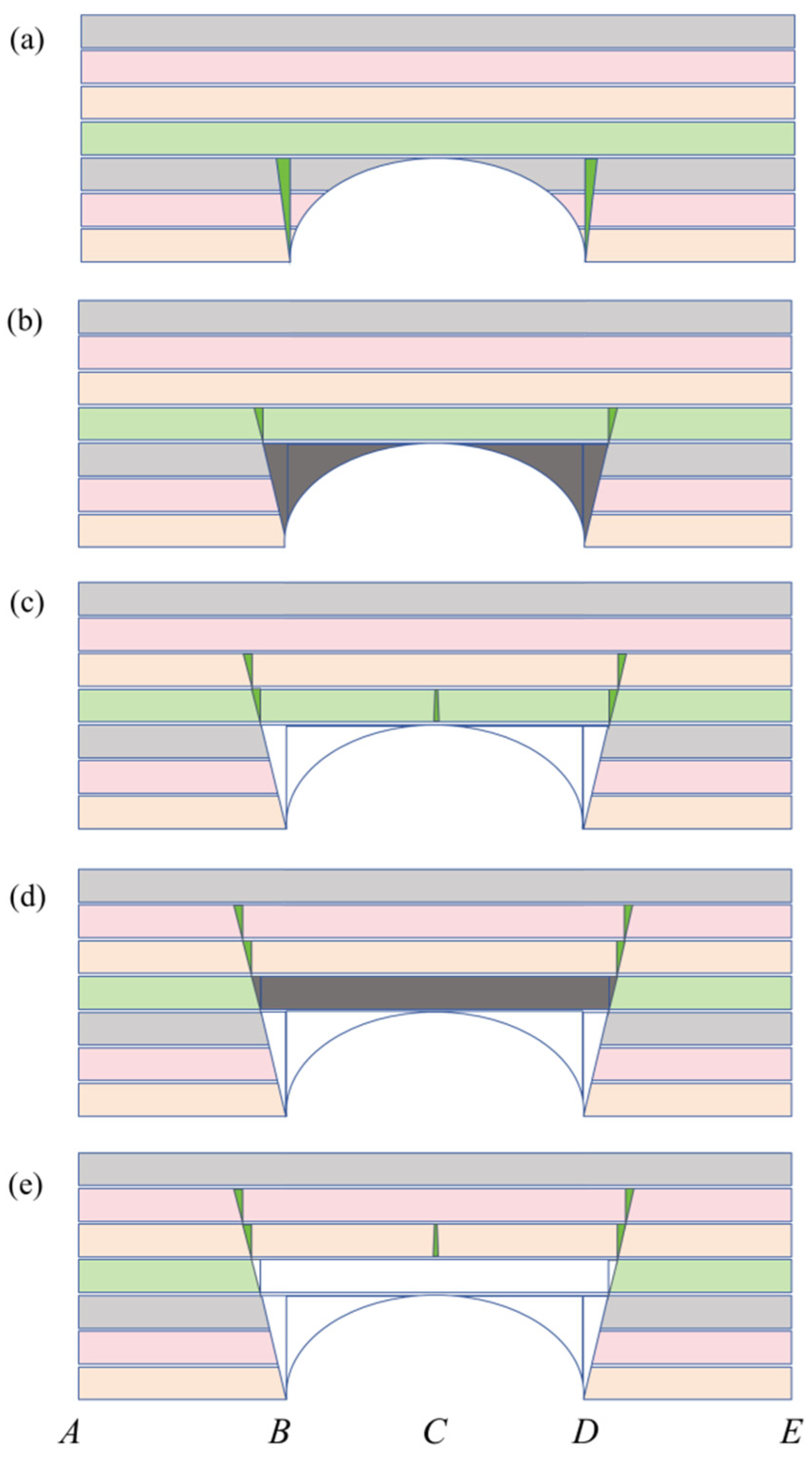
Figure 1. Evolution process of vault stratum fracturing and beam structure transformation: (a) initial fracturing, (b) cantilever beam instability, simply supported beam (c) fracturing and (d) failure, (e) layer-by-layer cyclic failure.
Applsci 16 07517 g001
Figure 2. Griffith strength theory and initiation criterion.
Applsci 16 07517 g002
Figure 3. Model of underground tunnel in bedded rock mass under non-axisymmetry.
Applsci 16 07517 g003
Figure 4. Simplified single beam models: (a) fixed-end beam (b) simply supported beam and (c) cantilever beam.
Applsci 16 07517 g004
Figure 5. Simplified composite beam models: (a) fixed-end beam (b) simply supported beam and (c) cantilever beam.
Applsci 16 07517 g005
Figure 6. Numerical calculation model of tunnel in layered rock mass.
Applsci 16 07517 g006
Figure 7. Evolution Process of Roof Stratum Separation of Arch Vault.
Applsci 16 07517 g007
Table 1. The vault stratum separation criterion.
Rλacbd f λ 1 f λ 2 f λ Criterion
0 < R < R 3 / > 0 > 0 > 0 > 0 > 0 > 0 > 0
R 3 < R < R 5 0 < λ < λ 1 < 0 > 0 < 0 > 0 < 0
λ 1 < λ > 0 > 0 > 0
R 5 < R < 1 0 < λ < λ 2 < 0 < 0 < 0 < 0 > 0
λ 2 < λ < λ 1 < 0 > 0 < 0
λ 1 < λ > 0 > 0 > 0
Notes: R = a 2 a + t 2 , R 3 = 0.434 , R 5 = 0.566 , λ 1 = 3 R 2 R + 1 3 R 2 + 3 R + 3 , λ 2 = 3 R 2 7 R + 3 3 R 2 5 R 1 .
Table 2. The vault stratum separation criterion ①.
24 σ t P R λ ac b d f λ 3 f λ 4 f λ Separation
> 0 0 < R < R 4 / > 0 > 0 > 0 > 0 > 0 > 0 > 0 No
R 4 < R 0 < λ < λ 4 < 0 < 0 < 0 Yes
λ 4 < λ > 0 > 0 No
< 0 0 < R < R 4 / > 0 > 0 > 0 > 0 > 0 No
R 4 < R < R 1 0 < λ < λ 4 > 0 < 0 > 0 < 0 < 0 Yes
λ 4 < λ > 0 > 0 No
R 1 < R < R 2 0 < λ < λ 3 < 0 < 0 < 0 < 0 > 0 No
λ 3 < λ < λ 4 > 0 < 0 < 0 No
λ 4 < λ > 0 > 0 > 0 No
R 2 < R < 1 0 < λ < λ 4 > 0 < 0 > 0 < 0 < 0 Yes
λ 4 < λ > 0 > 0 No
Notes: R = a 2 a + t 2 , R 1 = 5 25 24 σ t P + 1 6 , R 2 = 5 + 25 24 σ t P + 1 6 , R 4 = 1 + 1 + 24 σ t P 6 , λ 3 = 3 R 2 5 R + 2 σ t P + 2 3 R 2 + 3 R , λ 4 = 3 R 2 + R + 2 σ t P 3 R 2 + R + 2 .
Table 3. Comparison of results from numerical simulation and theoretical analytical methods.
Analysis MethodSeparation Thickness
(m)
Cantilever Beam End Stress (MPa)Fixed-End Beam End Stress (MPa)Simply Supported Beam Midspan Stress (MPa)
Numerical simulation5.204.662.592.38
Composite beam theory5.604.592.522.42
Relative error (%)7.141.532.781.65
Disclaimer/Publisher’s Note: The statements, opinions and data contained in all publications are solely those of the individual author(s) and contributor(s) and not of MDPI and/or the editor(s). MDPI and/or the editor(s) disclaim responsibility for any injury to people or property resulting from any ideas, methods, instructions or products referred to in the content.