1. Introduction
The creation of accessible built environments is a central goal of contemporary architecture, urban planning, and human-centered design. Accessibility is increasingly understood not simply as regulatory compliance, but as a precondition for participation, inclusion, health, and dignity. Recent work in the built-environment field has also emphasized that inclusive and accessible spaces require more than prescriptive guidelines alone, calling for evidence-based methods that better capture how people experience and use buildings and urban settings [
1,
2].
A persistent challenge is the gap between nominal compliance and functional accessibility. Environments may satisfy dimensional standards for clearances, slopes, or reach ranges, while still being difficult, fatiguing, or unsafe for users performing everyday tasks. This is especially relevant for older adults, people with mobility impairments, and users with diverse physical capabilities, whose interaction with space depends not only on geometry but also on posture, balance, strength, joint mobility, and task context [
3,
4]. Accessibility should thus be treated as a dynamic performance condition emerging from the interaction between the user, the task, and the environment, rather than as a purely static property of spatial layout [
1,
3].
Current computational approaches to accessibility assessment remain dominated by rule-based and geometry-driven methods. In BIM-based and automated compliance checking workflows, regulations are translated into machine-readable rules and evaluated against digital building models. These approaches have advanced substantially in recent years and improve consistency and efficiency in code checking [
5,
6]. However, their analytical focus remains largely centered on explicit requirements encoded in standards, making them well-suited to detecting formal non-compliance but less capable of identifying barriers that arise during embodied interaction, such as unstable movement, constrained posture, or excessive physical effort [
5,
6].
To address these limitations, research has increasingly explored simulation-based and human-centered methods. In accessibility research, simulation frameworks have been proposed to evaluate indoor environments for people with disabilities and to support the optimization of disability-friendly building operations and layouts [
7,
8]. Digital human modeling research has expanded the capacity to simulate posture, reach, and ergonomic interaction within architectural contexts, including design tools aimed at elderly users and mobility-constrained scenarios [
3]. These developments point toward a broader shift from static compliance checking toward performance-based accessibility assessment, in which environments are evaluated according to how well users can navigate, reach, transfer, or perform tasks within them.
Existing simulation approaches, however, present important trade-offs. Automated compliance methods are scalable but often lack rich human representation [
5,
6]. Digital human modeling and ergonomic tools can capture posture and biomechanical constraints, yet many remain difficult to integrate into iterative design workflows or interactive building models [
3,
9]. Recent reviews of digital and virtual technologies for biomechanical and ergonomic assessment show strong analytical potential, but also highlight persistent challenges in usability, data requirements, and real-time applicability [
9,
10]. As a result, no widely adopted framework yet combines structured task definition, adaptable motion generation, and quantitative biomechanical analysis for accessibility evaluation in built environments.
This gap matters because accessibility barriers often emerge during movement and task execution, not only in plan geometry. A route may appear compliant yet still impose excessive mechanical demands during walking, stair negotiation, reaching, or support-based movement. Capturing such barriers requires methods that represent the temporal and physical dimensions of user–environment interaction and that produce interpretable measures of feasibility, effort, and load [
7,
8,
10].
In response, this work proposes a modular simulation framework for accessibility-oriented virtual human evaluation. The framework integrates procedural kinematic planning with inverse dynamics analysis to simulate task execution in built environments and estimate the associated joint forces and torques. By combining deterministic motion generation with biomechanical computation, the proposed system supports a shift from purely geometric verification toward performance-based accessibility assessment grounded in dynamic human behavior. The principal contributions of this work are: (1) a modular, task-driven simulation pipeline that decomposes high-level accessibility scenarios into executable motion primitives; (2) a procedural kinematic planning framework based on gait abstraction and inverse kinematics that generates deterministic, environment-adaptive motion trajectories; (3) a stabilized Newton–Euler inverse dynamics formulation with integrated contact force modeling for real-time joint load estimation; and (4) a comparison of the resulting joint forces against published biomechanical reference data across three representative locomotion scenarios.
The remainder of this paper is organized as follows:
Section 2 reviews related work;
Section 3 describes the system architecture;
Section 4 presents the kinematic planning framework;
Section 5 details the inverse dynamics formulation;
Section 6 reports comparison results; and
Section 7 concludes with contributions, limitations, and future research directions.
2. Related Work
The evaluation of accessibility in built environments has been addressed through a variety of computational and simulation-based approaches, ranging from rule-based compliance checking to advanced human-centered simulation systems. Existing methods differ in how they represent human interaction, the level of physical realism they incorporate, and their suitability for performance-based assessment.
Table 1 provides a structured overview of the reviewed approaches across key evaluation dimensions, summarizing their capabilities and limitations before the detailed discussion that follows.
2.1. Rule-Based and BIM-Integrated Accessibility Checking
A large body of work focuses on automated accessibility evaluation within Building Information Modeling environments. These approaches typically encode regulatory requirements, such as minimum clearances, ramp slopes, and reach ranges, into rule-based systems evaluated directly on digital building models. Early work in automated code checking demonstrated the feasibility of translating building regulations into machine-readable rules and applying them to BIM data structures [
11,
12].
More recent systems extend this paradigm by incorporating semantic modeling and constraint checking to improve flexibility and coverage [
13,
14]. For example, rule classification frameworks and ontology-based approaches have been proposed to support scalable compliance verification across diverse building types [
15]. While these methods are effective for identifying violations of explicit design standards, they remain fundamentally limited to static geometric evaluation. They do not account for how users physically interact with the environment, nor do they capture task-dependent challenges such as constrained movement paths or dynamic balance requirements.
2.2. Path-Based and Navigation-Oriented Accessibility Analysis
Another line of research investigates accessibility through navigation and pathfinding analysis. These approaches evaluate whether routes within a built environment are traversable for users with specific mobility constraints, often using graph-based representations or navigation meshes. Studies in this domain have explored wheelchair-accessible routing, evacuation planning, and pedestrian flow analysis [
16].
In BIM-integrated contexts, accessibility analysis has been extended to simulate navigation paths directly within digital building models [
17]. These methods provide valuable insight into spatial connectivity and barrier-free routing. However, they typically represent users as simplified agents or point masses, without detailed articulation or biomechanical constraints. As a result, they cannot evaluate fine-grained interaction tasks such as reaching, grasping, or negotiating complex geometries like stairs and confined spaces.
2.3. Ergonomic and Digital Human Modeling Approaches
Digital human modeling tools have been widely used in ergonomics and workplace design to evaluate human interaction with environments and products. Systems such as JACK, RAMSIS, and Santos incorporate articulated human models with anthropometric variability and enable analysis of posture, reachability, and visibility [
18]. These tools have also been applied to accessibility studies, particularly for inclusive design and usability assessment.
More advanced DHM platforms integrate biomechanical analysis, allowing estimation of joint forces, muscle activity, or fatigue during task execution [
19]. While these systems provide detailed insight into human performance, they are often designed for offline analysis and require significant manual setup, including pose specification and task definition. Additionally, their integration with real-time interactive environments or BIM workflows remains limited, reducing their applicability for iterative design evaluation.
2.4. Virtual Human Simulation and Physics-Based Methods
Virtual human simulation within interactive 3D environments has been explored to combine spatial modeling with dynamic human behavior. Animation-based approaches use pre-recorded motion data or motion graphs to generate plausible human movement in virtual environments [
20,
21]. These methods offer visual realism and efficiency but remain constrained by the available motion dataset and lack adaptability to novel tasks or environmental configurations.
Physics-based simulation approaches model the human body as an articulated system governed by dynamic equations of motion. Such methods enable physically consistent interaction with the environment and can, in principle, capture balance, contact forces, and dynamic stability. However, they are often computationally expensive and difficult to control, particularly in real-time scenarios involving complex tasks [
22].
Hybrid approaches have been proposed to balance realism and controllability by combining kinematic planning with dynamic simulation [
23]. These methods typically use inverse kinematics or procedural motion generation to define trajectories, followed by dynamic evaluation or control-based refinement. While promising, existing implementations mostly target animation or robotics applications and do not explicitly target accessibility assessment or integration with structured task definitions.
2.5. Positioning the Proposed Framework
The preceding review reveals a consistent pattern: each category of method addresses a distinct aspect of accessibility evaluation, yet none integrates all the capabilities required for performance-based assessment. Rule-based and BIM-integrated methods provide scalable, automated compliance checking, ensuring that environments meet prescribed geometric and regulatory requirements. Navigation-based analyses extend this capability by evaluating route feasibility and spatial connectivity for users with mobility constraints. Digital human modeling and ergonomic tools introduce articulated human representation and enable detailed analysis of posture, reachability, and, in some cases, biomechanical load. Physics-based and hybrid simulation methods further provide physically consistent interaction and dynamic motion generation.
Recent work has extended biomechanical and digital-human simulation toward accessibility-oriented and real-time applications. Miki et al. [
24] proposed a biomechanical simulation approach for enhancing XR accessibility through anthropometrically diverse virtual users, directly targeting accessibility but without a task-driven, environment-embedded architecture. Moon et al. [
25] demonstrated real-time biomechanical simulation for interactive target inference, illustrating the growing feasibility of coupling biomechanical modeling with real-time interactive systems, though outside the accessibility or built-environment domain. Zuo et al. [
26] developed an embodied human simulation framework for interactive robotics design, likewise emphasizing generalizable digital human embodiments, but their evaluation remains largely kinematic and reinforcement-learning-driven rather than grounded in a deterministic, reproducible force-estimation pipeline. Relative to this landscape, the framework proposed here combines (i) deterministic, procedural task-to-motion planning, (ii) a full inverse-dynamics force-estimation pipeline compared against in vivo reference data, and (iii) real-time operation inside an interactive, game-engine-based design workflow which is a combination not jointly offered by the systems above, each of which provides only a subset of these capabilities.
Ratings in
Table 1 were assigned as follows: ‘High’ denotes sub-100 ms per-frame computation suitable for real-time interaction; ‘Medium’ denotes computation feasible for near-real-time or batch evaluation; ‘Low’ denotes offline-only processing. For Biomechanical Analysis, ‘Yes’ denotes literature-compared joint force/torque output; ‘Partial’ denotes force estimation without joint-level comparison; ‘No’ denotes no force computation. Ratings are derived from the cited sources’ reported performance characteristics.
Table 1.
Comparison of existing accessibility assessment approaches across key evaluation dimensions.
Table 1.
Comparison of existing accessibility assessment approaches across key evaluation dimensions.
| Approach | Human
Representation | Task-Driven
Motion | Biomechanical
Analysis | Design
Integration | Real-Time
Capable | Representative Systems |
|---|
| BIM rule-based | None | No | No | High | Yes | [11,12,13,14,15] |
| Navigation/pathfinding | Point agent | No | No | Medium | Yes | [16,17] |
| Digital human modeling | Articulated | Partial (manual) | Partial | Low | No | [18,19,24] |
| Physics-based simulation | Articulated | No | Yes | Low | No | [22,26] |
| Hybrid kinematic-dynamic | Articulated | Partial | Partial | Low | Partial | [23,25] |
| Proposed framework | Articulated | Yes (procedural) | Yes (inverse dynamics) | Medium | Yes | This work |
Despite these advances, a fundamental limitation persists. Accessibility is still predominantly evaluated as a static or geometry-driven property, rather than as a dynamic condition emerging from human-environment interaction. Existing approaches tend to isolate individual aspects of accessibility, such as clearance verification, path traversability, or posture assessment, without integrating them into a unified framework that captures how users perform tasks within real spatial contexts.
As a result, many accessibility barriers remain difficult to detect using current tools. Environments that satisfy regulatory criteria and appear navigable at a path level may still impose excessive physical demands during task execution. Activities such as reaching, transferring, stair negotiation, or assisted locomotion involve coordinated movement, balance control, and force generation, all of which can significantly affect usability, safety, and comfort. These factors are particularly critical for populations with reduced mobility, strength limitations, or age-related functional decline, yet are rarely captured in conventional accessibility assessments.
The disconnect between simulation capability and accessibility-oriented workflows is particularly consequential. While digital human modeling and physics-based simulation provide detailed insight into human performance, they are often not designed for task-driven accessibility analysis within built environment contexts. Many systems require manual pose specification, lack integration with structured scenario definitions, or are unsuitable for real-time or iterative design evaluation. Conversely, methods well integrated into design workflows, such as BIM-based compliance checking, typically cannot represent dynamic human behavior and biomechanical constraints.
Taken together, these gaps point to the need for a framework that unifies: (1) task-driven motion generation grounded in environmental context, (2) deterministic and reproducible simulation of human interaction, and (3) quantitative assessment of biomechanical demand during task execution. Such a framework is essential for advancing from prescriptive compliance-based design toward performance-based accessibility evaluation, in which environments are assessed according to how effectively they support users in performing everyday activities.
The framework proposed in this work addresses this gap by integrating procedural kinematic planning with inverse dynamics analysis in a modular simulation environment. By enabling structured task execution and real-time estimation of joint forces and torques, the system supports accessibility evaluation that extends beyond geometric verification toward a dynamic, human-centered assessment of physical feasibility and effort within built environments.
3. System Architecture
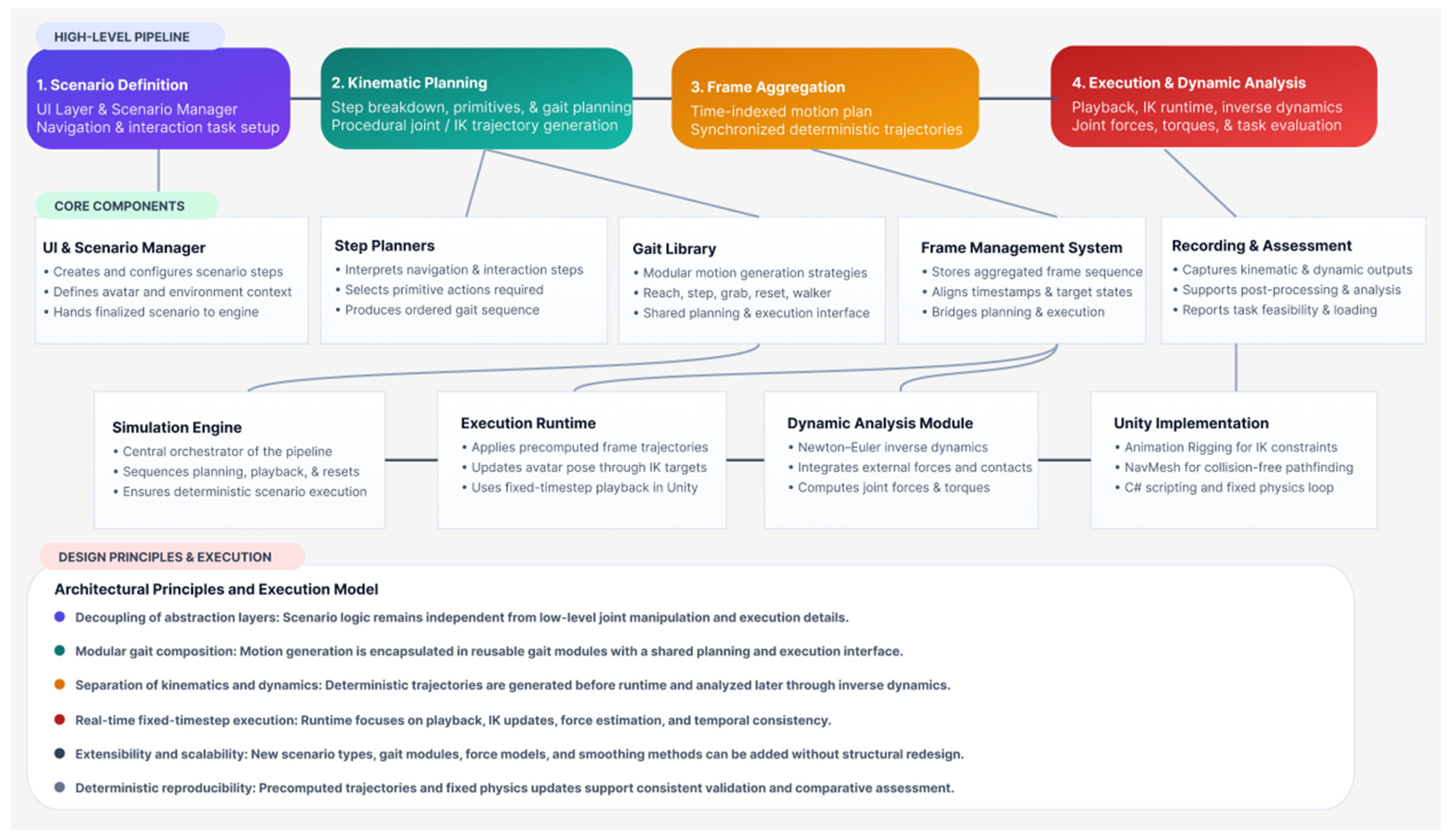
The proposed framework follows a modular, pipeline-oriented architecture designed to translate high-level task descriptions into executable avatar motion and biomechanical load estimation. The system separates planning, motion synthesis, execution, and analysis into distinct yet interconnected subsystems. This separation ensures extensibility, clarity of responsibility between components, and controlled propagation of data across the simulation lifecycle.
At a high level, the workflow begins with a structured simulation scenario that defines a sequence of task steps. These steps may include navigation to a waypoint, interaction with an object, or a combination of both. The scenario is processed by the kinematic planning subsystem, which decomposes each step into primitive motion elements. These primitives are then translated into a set of gaits, each responsible for generating specific joint or inverse kinematic (IK) trajectories. The resulting motion plan is stored in a time-indexed frame structure and passed to the execution layer. During runtime playback, the inverse dynamics subsystem evaluates joint forces and torques required to realize the generated motion. Finally, the recorded kinematic and dynamic data are made available for assessment and analysis.
Figure 1 illustrates this high-level architecture and the data flow between subsystems.
3.1. Architectural Principles
The architecture is governed by three primary design principles:
Decoupling of abstraction layers. High-level task definitions are kept independent from low-level motion algorithms. Scenario interpretation does not directly manipulate joint transforms; instead, it produces a structured description of required movement primitives. This separation allows new task types or movement strategies to be introduced without altering core execution logic.
Modular gait composition. All motion generation is encapsulated within discrete gait modules. Each gait operates autonomously, implementing its own trajectory planning algorithm while adhering to a shared execution interface. This design supports extensibility and facilitates the addition of new locomotion or manipulation behaviors.
Separation of kinematics and dynamics. Kinematic planning generates deterministic motion trajectories without embedding physical force calculations. Dynamic analysis is performed subsequently, using the generated motion as input. This separation improves stability, simplifies development and debugging, and allows dynamic algorithms to evolve independently of motion planning.
Together, these principles ensure that the framework remains analytically tractable, computationally efficient, and open to future extension without requiring structural redesign.
3.2. End-to-End Simulation Pipeline
The complete pipeline proceeds through seven sequential stages, as follows:
Scenario Definition. A simulation scenario consists of a sequence of user-defined steps. Each step specifies either a navigation objective (e.g., reaching a waypoint) or an interaction task (e.g., opening a door). The scenario is environment-dependent and executed in the context of a preconfigured avatar.
Step Breakdown. The kinematic planning subsystem processes each scenario step and determines the primitive actions required for its completion. For example, a navigation step may result in a series of locomotion primitives, while an interaction step may require reaching, grasping, and manipulation movements. This stage produces an ordered list of required gaits.
Gait Planning. Each gait independently computes trajectories for the bones or IK targets it controls. During planning, trajectories are sampled and stored in a structured format. The output is a sequence of time-indexed frames representing joint or target states.
Frame Aggregation. The outputs of multiple gaits are concatenated and synchronized into a unified frame sequence. Each frame contains spatial information for all controlled segments, along with a timestamp indicating its execution start time.
Execution Phase. The motion plan is executed in the simulation engine. Inverse kinematics constraints update limb configurations according to the stored frame data. The avatar’s pose evolves deterministically according to the predefined trajectory.
Dynamic Analysis. During execution, the inverse dynamics subsystem computes internal joint forces and torques using the avatar’s instantaneous kinematic state. External forces are incorporated as needed, based on detected environmental interactions.
Data Recording and Assessment. Kinematic and dynamic data are recorded throughout execution and subsequently processed by the assessment module to generate quantitative feedback on joint loading and task feasibility.
This structured pipeline ensures that each subsystem performs a clearly defined role while maintaining a coherent flow of information. Importantly, because kinematic planning (stages 1–4) is fully completed before execution begins (stages 5–7), the system guarantees deterministic and reproducible simulation outcomes.
3.3. Core Components
The simulation engine acts as the central orchestrator of the system coordinating communication between the following principal components:
UI Layer and Scenario Manager. Responsible for creating and configuring simulation steps. Once the scenario is finalized, control is passed to the simulation engine.
Step Planners. Translate scenario steps into motion primitives, determining which gaits are required and in what sequence they should be executed.
Gait Library. A collection of gait implementations, each encapsulating a specific movement strategy. Gaits share a common base interface defining planning and execution behavior.
Frame Management System. Stores and organizes generated trajectories, serving as the shared data structure between kinematic planning and execution.
Dynamic Analysis Module. Implements the inverse dynamics formulation, receiving joint kinematics and external force information during runtime and computing the corresponding joint reactions.
Recording and Playback Modules. Capture kinematic trajectories and dynamic outputs for post-processing and visualization.
The simulation engine sequentially processes scenario steps, generates the necessary gait plans, executes them, and triggers dynamic evaluation. After completion of all steps, the system resets the avatar to a neutral state and transfers recorded data to the assessment layer.
3.4. Real-Time Execution Model
All kinematic and dynamic updates are synchronized with the physics timestep of the simulation environment. Kinematic planning is performed before execution, ensuring runtime computation focuses primarily on trajectory playback and force estimation. The inverse dynamics algorithm operates during fixed physics updates to maintain temporal consistency between motion sampling and force calculation.
This execution strategy balances computational efficiency and analytical fidelity. By separating planning from runtime evaluation, the system reduces computational overhead during playback while preserving deterministic motion behavior. The computational cost of the inverse dynamics subsystem scales linearly with the number of skeletal segments, ensuring real-time performance for scenarios of moderate complexity.
3.5. Extensibility and Scalability
The architecture is designed to accommodate future extensions without structural modification. New gait types can be implemented by deriving from the shared base class and integrating into the gait library. Alternative inverse dynamics formulations, additional external force models, or refined smoothing techniques can be introduced within the dynamic analysis subsystem independently of the planning layer.
Similarly, additional scenario step types can be integrated by extending the step breakdown mechanism. Because scenario logic does not directly manipulate skeletal transforms, changes at the planning level do not propagate unintended side effects to execution or analysis modules.
This modularity ensures that the framework can evolve toward more complex motion strategies, richer biomechanical modeling, or broader accessibility use cases while maintaining architectural coherence. In particular, the gait library could be extended to support wheelchair locomotion, crutch-assisted movement, or upper-limb manipulation tasks, broadening the range of user profiles and accessibility scenarios the system can evaluate.
3.6. Implementation Details
The proposed framework is implemented within the Unity real-time development environment, leveraging its support for articulated hierarchies, fixed-timestep physics updates, and extensible C# scripting. The implementation integrates procedural motion generation, navigation, deterministic playback, and inverse dynamics evaluation within the architectural structure described above.
Two engine packages play a central role: Unity Animation Rigging and NavMesh Navigation. Animation Rigging provides the Inverse kinematics (IK) constraints, which are applied to the avatar’s skeletal hierarchy. Motion is generated by directly controlling IK targets rather than playing predefined animation clips. Two-bone IK constraints are used for articulated limbs, enabling precise end-effector positioning during task execution. NavMesh, meanwhile, enables the system to compute collision-free paths within the environment. The resulting waypoint sequences are sampled and translated into locomotion primitives, maintaining a clear separation between pathfinding and gait generation.
The simulation engine integrates planning, execution, and analysis within a staged pipeline. Scenario steps are first translated into motion primitives, producing a global sequence of time-indexed frames. During execution, the avatar is reset to a neutral configuration, and IK targets are updated sequentially according to the precomputed trajectory. Inverse dynamics computations are performed during fixed-timestep updates, and both kinematic and dynamic data are recorded for subsequent assessment.
The implementation relies on structured representations of the articulated body and its state. Each skeletal segment stores transform references, mass properties, inertia tensors, and hierarchical relationships. Kinematic quantities, including angular and linear accelerations, are computed during forward recursion, while net forces and torques are accumulated during backward recursion. Motion trajectories are encoded as a sequence of time-indexed frames containing target positions and rotations for controlled segments.
Because kinematic planning is completed prior to execution, runtime computation is limited to frame playback, inverse dynamics evaluation, and contact handling, keeping the computational load predictable and bounded. All dynamic computations are executed within the fixed timestep loop, ensuring temporal consistency for derivative estimation. The computational cost of the inverse dynamics subsystem scales linearly with the number of skeletal segments, allowing real-time performance for moderate scenario complexity. Deterministic behavior is ensured through precomputed trajectories and fixed-timestep execution. Identical scenarios produce identical motion and consistent force outputs, supporting reproducible comparison and comparative accessibility assessment.
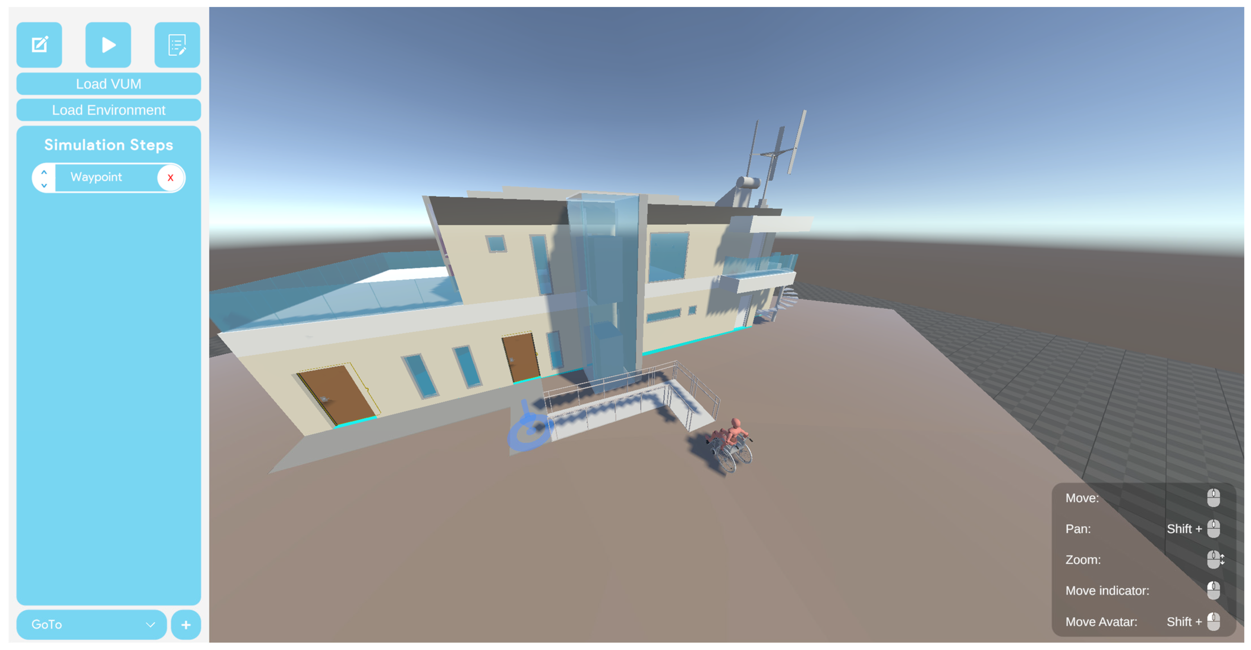
The system is operated through a streamlined graphical interface that enables users to select both the target environment for evaluation and a virtual human model representing individuals with specific disabilities. Within the selected environment, users may define a sequence of simulation tasks aimed either at assessing the virtual model’s ability to navigate toward a designated waypoint or at evaluating its capacity to interact with environmental objects, such as doors and other interactive elements.
Figure 2 shows an example scenario configured within the simulator interface.
3.7. Computational Performance
To substantiate the real-time performance claims made in
Section 3.4, we measured per-frame execution time across the three scenarios on a consumer-grade workstation (Intel Core i7, 16 GB RAM, NVIDIA GTX 1660, running Unity 2022 LTS). Mean inverse dynamics computation time per frame was 2.8 ms (SD = 0.6 ms) for a 22-segment skeletal hierarchy, remaining well within the 16.7 ms budget required for real-time playback at 60 fps, leaving substantial headroom for concurrent rendering, physics, and navigation computations.
4. Kinematic Planning Framework
The kinematic planning framework is responsible for transforming high-level simulation steps into executable motion trajectories for the virtual human avatar. Rather than relying on pre-authored animation clips, the system generates motion procedurally based on the semantic description of the task and the spatial configuration of the environment. This approach enables adaptability to varying waypoint positions, object locations, and scenario sequences while maintaining deterministic and analyzable motion output.
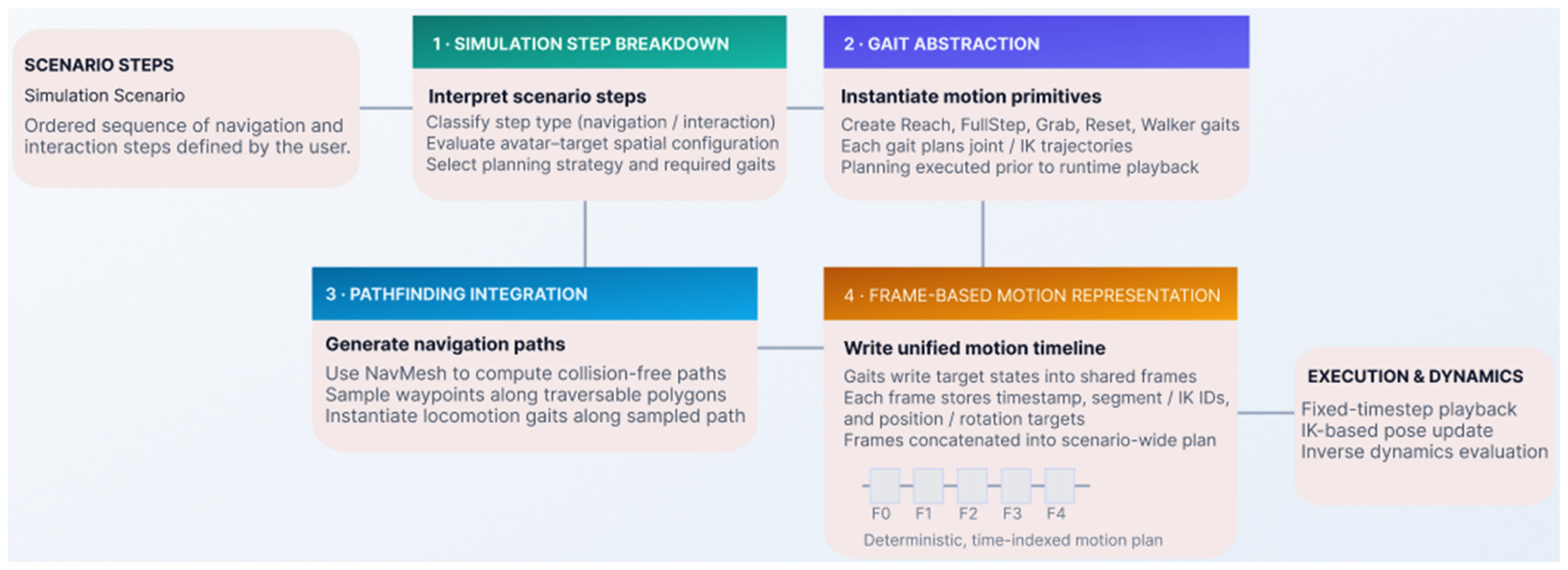
The framework establishes a structured pipeline that converts abstract task definitions into time-indexed kinematic trajectories organized into four tightly integrated components: (1) Simulation step breakdown, (2) Gait abstraction and modular motion generation, (3) Pathfinding integration, and (4) Frame-based motion representation. Together, these components provide a controlled, extensible transition from scenario-level semantics to articulated skeletal motion.
Figure 3 provides an overview of the framework and the relationships between these components.
4.1. Simulation Step Breakdown
The simulation step breakdown forms the entry point of the kinematic planning subsystem interpreting each scenario step to determine the primitive movement actions required for its execution. A simulation scenario consists of an ordered sequence of steps, such as navigating to a waypoint or interacting with an object, and each step type is associated with a distinct planning strategy. During breakdown, the system evaluates the type of scenario step (for example, navigation or interaction), the spatial configuration of the avatar relative to the target, and the contextual requirements of the task. Based on this evaluation, the planner selects gaits that collectively achieve the intended outcome: a navigation step typically yields locomotion primitives along a computed path, an interaction step may invoke a combination of reach, grasp, and manipulation gaits, and more complex steps are decomposed into simpler primitives.
The breakdown mechanism separates movement selection logic from movement execution. In the first phase, the system determines which simulation step type applies and selects the appropriate planning algorithm. In the second phase, it invokes the relevant gait generators. This two-phase structure ensures that planning decisions are made before any motion data is generated, which supports early feasibility detection and clean separation of concerns.
The output of this stage is an ordered list of required gaits. If a scenario step cannot be decomposed into executable primitives, the system raises an early simulation error indicating that environment configuration, avatar capabilities, or scenario definition is infeasible. This fail-fast behavior prevents unnecessary computation and gives actionable feedback to the user at the scenario design stage.
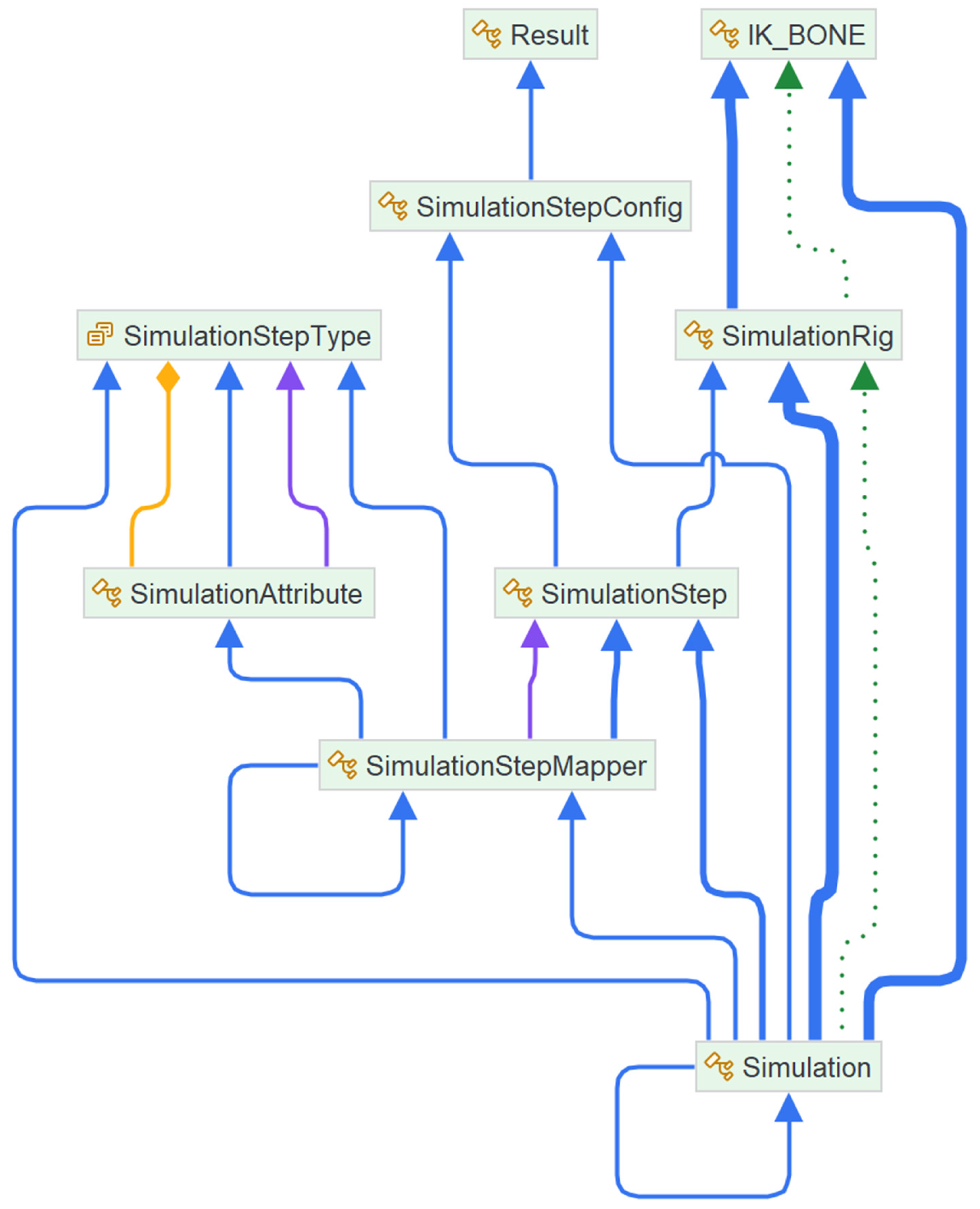
Figure 4 shows the type dependency diagram for the simulation step breakdown subsystem, illustrating the relationships between step types, planners, and gait generators. This diagram reflects the decoupling principle described in
Section 3.1: scenario interpretation is fully separated from motion generation, allowing new task types to be introduced without modifying execution logic. This structural property directly supports the extensibility discussed in
Section 3.5.
4.2. Gait Abstraction and Modular Motion Generation
Within the framework, gaits represent the fundamental motion units, each encapsulating a reusable self-contained motion generation strategy that controls a specific subset of the avatar’s skeletal structure. All gaits inherit from a shared abstract base class defining a common two-phase lifecycle: planning and execution. During planning, a gait computes the trajectories required to achieve its objective, which may involve joint-space rotations such as finger closure during grasp, task-space inverse kinematics target positions such as a hand reaching a handle or coordinated multi-segment trajectories such as a full leg swing during stepping.
The planning algorithm, implemented in each concrete gait class, calculates a sequence of spatial targets sampled at discrete time intervals and stores them in the shared frame structure. This phase runs before runtime playback, ensuring that the entire motion sequence is available before execution begins. This separation guarantees determinism and allows validation, smoothing, or feasibility checks before dynamic analysis.
The execution phase is standardized across all gaits and defined in the abstract base class. During runtime, the simulation engine iterates over the precomputed frames and applies the stored transformations to the controlled segments or IK targets. Because execution follows a unified temporal progression model, motion primitives remain synchronized and composite tasks stay temporally coherent.
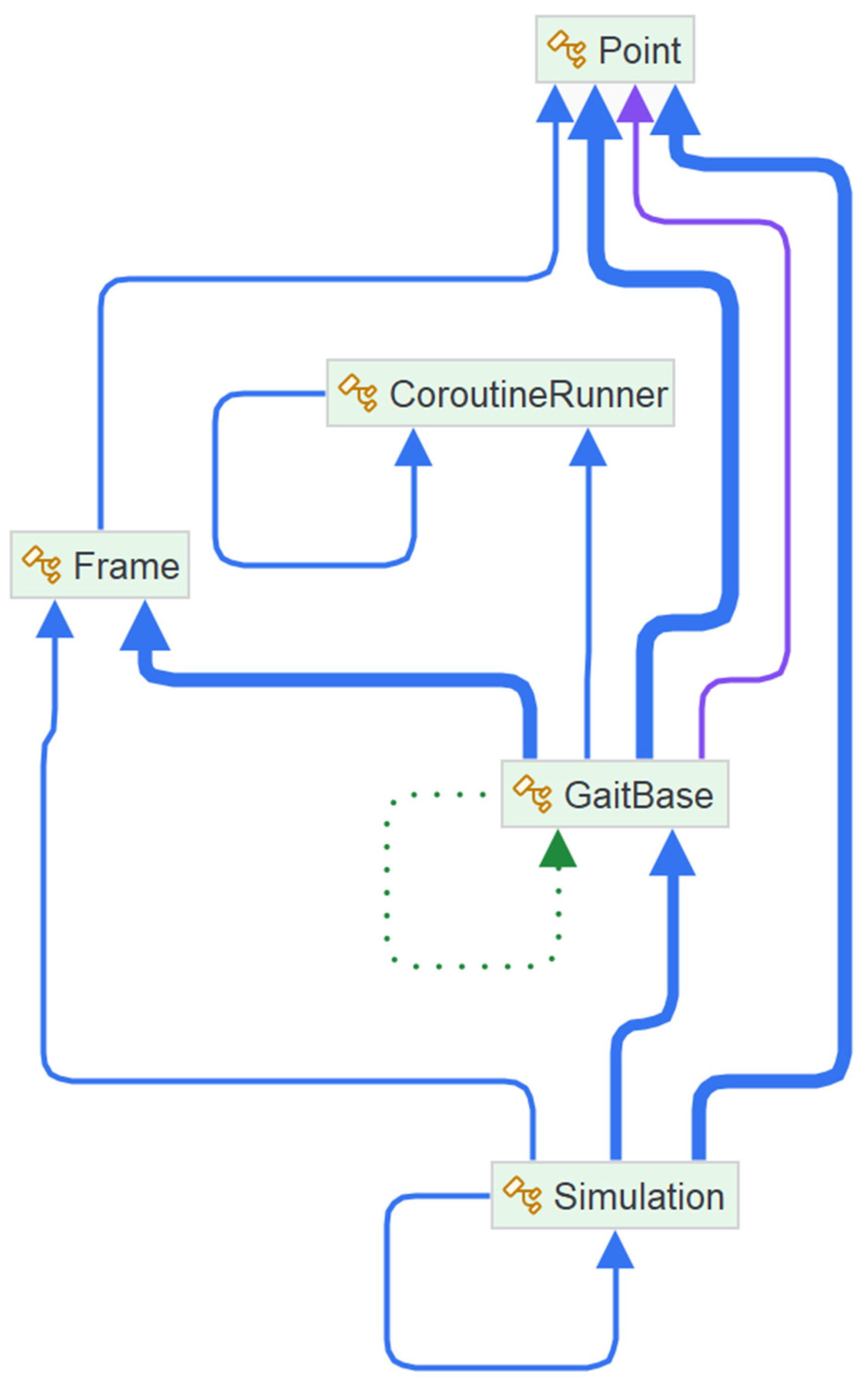
Figure 5 illustrates the dependency between gaits, frames, and the simulation core, showing how concrete gait classes interact with the shared frame structure and the execution engine. This diagram reflects the modular gait composition principle described in
Section 3.1: each gait operates autonomously behind a shared execution interface, writing into the common frame structure without direct dependencies on other gait implementations. It also supports the extensibility described in
Section 3.5, since new locomotion or manipulation behaviors can be added to the gait library without modifying existing gaits or the execution engine.
4.3. Implemented Gait Types
The current implementation includes five core gait types. Each gait explicitly defines which skeletal segments it affects, preventing interference between concurrent motion primitives and enabling safe sequential composition:
ReachGait. Moves the hand IK target toward a specified spatial location, generating a smooth trajectory between the current and target positions to ensure spatial alignment for interaction.
FullStepGait. Generates a complete stepping motion including lift, forward swing, and placement phases; step direction and length are derived from the navigation output.
GrabGait. Controls finger joint rotations to simulate grasping, typically transitioning from an open to a closed configuration within defined angular limits.
ZeroGait and ResetGait. Restore individual segments or the entire skeleton to neutral configurations.
WalkerGait. Coordinates limb movement during assisted locomotion such as walking with a support frame or mobility aid.
The modular design of the gait library allows new motion behaviors to be introduced via the shared base interface, without modifying existing gaits or the execution engine.
4.4. Trajectory Generation Strategies
Trajectory generation depends on motion type. Task-space trajectories are used for IK targets such as hands and feet, where end-effector position must conform to spatial constraints defined by the environment. Joint-space trajectories are used when direct rotational control is required, such as finger articulation during grasping. All trajectories are discretized at fixed temporal intervals aligned with the simulation timestep ensuring compatibility with inverse dynamics calculations and enabling accurate computation of velocities and accelerations via finite differencing.
For locomotion, the stepping trajectory follows the path computed by the navigation subsystem, including vertical displacement for foot lift. For reach tasks, interpolated spatial trajectories connect initial and target positions smoothly. In both cases, trajectory smoothness is a prerequisite for stable inverse dynamics computation, since abrupt kinematic discontinuities would produce unreliable force estimates. Smoothing considerations are discussed further in
Section 5.
4.5. Pathfinding Integration
For navigation-related steps, the planning subsystem relies on a pathfinding mechanism based on a navigation mesh representation of the environment. The NavMesh algorithm evaluates traversable polygons and computes a collision-free path between the avatar’s current position and the target waypoint expressed as a sequence of spatial waypoints.
Discrete samples along this path determine where locomotion gaits are instantiated. Each sampled segment corresponds to one or more FullStepGait instances. Step orientation and length are derived from path direction and curvature, ensuring spatial consistency with the environment layout.
If no valid path exists, the system reports an early feasibility error before motion generation proceeds. This aligns with the fail-fast behavior of the step breakdown subsystem described in
Section 4.1, providing consistent error handling across both planning and pathfinding stages.
4.6. Frame-Based Motion Representation
All gait planning outputs are stored in a unified frame-based data structure that bridges kinematic planning and runtime execution. Each frame contains a timestamp marking its start time, identifiers for the controlled skeletal segments or inverse kinematics targets, and the corresponding target position and/or rotation values for each controlled element. Frames are stored sequentially in a centralized structure, forming a complete time-indexed motion plan spanning the entire scenario. This representation provides several advantages:
Deterministic Execution. Since trajectories are fully precomputed, playback is reproducible across simulation runs.
Synchronization Across Gaits. All gaits write into a shared timeline, guaranteeing temporal alignment.
Compatibility with Dynamic Analysis. Evenly sampled kinematic data support derivative computation required by inverse dynamics.
Post-Processing Capability. Frames can be smoothed, inspected, or replayed independently of the planning logic.
Debugging and Visualization. Individual frames can be examined during development to verify trajectory correctness.
These properties collectively make the frame structure a foundational design choice, enabling the clean separation of planning, execution, and analysis that characterizes the overall architecture.
4.7. Aggregation and Stability Considerations
When multiple motion primitives are required, their outputs are concatenated into a continuous frame sequence. The simulation engine ensures that the end state of one gait matches the initial state of the next, prevents unintended temporal overlap, and inserts transition frames where necessary to preserve continuity. Without this aggregation step, discontinuities at gait boundaries would introduce kinematic artifacts that propagate into the inverse dynamics computation as spurious force spikes.
Complex behaviors are thus composed from simpler primitives while preserving structural coherence. A key advantage of this architecture is its deterministic behavior: because all kinematic trajectories are precomputed and stored, runtime execution does not depend on real-time solver conditions. This determinism is essential for biomechanical comparison, for comparing simulated forces against values reported in the literature, for conducting sensitivity analyses of smoothing parameters, and for performing reproducible accessibility assessment. The implications of this determinism for the evaluation methodology are discussed in
Section 6.
5. Inverse Dynamics
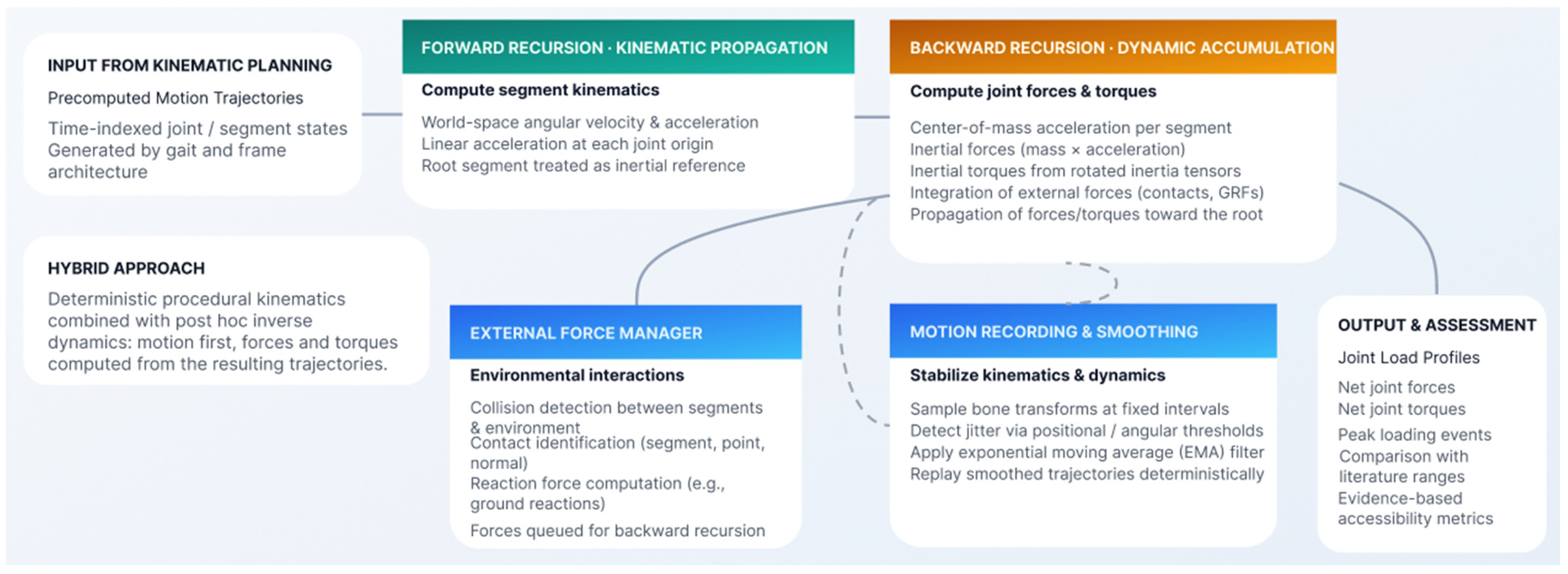
While the kinematic planning framework generates geometrically consistent motion trajectories, accessibility-oriented evaluation requires quantitative insight into the mechanical demands imposed on the virtual human. To provide this, the simulation framework integrates an inverse dynamics module that estimates joint forces and torques required to produce the observed motion under gravitational and environmental loads (see
Figure 6). The subsystem operates on the precomputed trajectories generated by the gait and frame architecture. By separating kinematic generation from dynamic computation, the system ensures deterministic motion synthesis while enabling physically interpretable force estimation. This section presents the mathematical formulation, computational structure, external force integration, and numerical stabilization mechanisms that collectively support reliable biomechanical analysis.
5.1. Rationale for the Hybrid Approach
During early development, several motion simulation strategies were evaluated, including PID-controlled articulated joints driven by physics engines, fully articulated rigid-body simulations, and procedural inverse kinematics combined with post hoc inverse dynamics. Purely physics-driven approaches can produce realistic motion only under careful tuning and are prone to instability or oscillatory behavior in complex articulated systems, whereas animation-driven techniques yield visually plausible movement but lack quantitative biomechanical interpretability.
The adopted hybrid approach combines procedural kinematic planning with inverse dynamics computation: motion is generated deterministically using inverse kinematics and gait planning, and forces and torques are then computed from the resulting motion. This separation ensures stable, controllable movement while preserving biomechanical plausibility and reproducibility.
5.2. Mathematical Foundation: Newton–Euler Formulation
The inverse dynamics algorithm is based on a Newton–Euler recursive formulation for articulated rigid-body systems, aimed at computing the net joint forces and torques required to reproduce the observed segment accelerations under gravitational and external loads. The computation proceeds in two stages, a forward recursion performing kinematic propagation and a backward recursion performing dynamic accumulation, with all quantities evaluated in world coordinates to preserve consistency across the articulated hierarchy.
5.3. Forward Recursion: Kinematic Propagation
In the forward pass, the algorithm computes the angular and linear kinematic quantities for each segment: angular velocity, angular acceleration, and the linear acceleration at the joint origin. The recursion begins at the root segment, whose angular velocity and acceleration are set to zero, or defined by global constraints if treated as inertial. For each child segment, local joint angular quantities are transformed into world space and combined with the parent kinematics, while linear acceleration is propagated according to standard rigid-body relations:
where
is the linear acceleration at the child joint,
is the linear acceleration at the parent joint,
is the angular acceleration at the parent joint,
is the parent angular velocity,
is the vector from parent joint to child joint.
The forward pass yields a complete set of world-space angular and linear accelerations for all segments.
5.4. Backward Recursion: Dynamic Accumulation
The backward pass computes internal forces and torques, starting from terminal segments and propagating toward the root. For each segment, the following steps are performed:
Center-of-Mass Acceleration. The acceleration of the segment’s center of mass is computed:
Inertial Force. The inertial force is computed as:
where
m is the segment mass.
Inertial Torque. The inertia tensor is rotated into world space, and angular acceleration contributions are computed to obtain inertial torque.
External Forces. Any applied external forces (e.g., contact forces) are added to the segment’s force balance.
Force and Torque Propagation. Forces and torques from child segments are transformed and accumulated:
The final output for each segment consists of:
Net joint force,
Net joint torque.
These values represent the net joint reaction force required to produce the observed motion under applied loads.
5.5. External Force Modeling
Inverse dynamics requires explicit modeling of environmental interactions, since motion alone does not account for contact forces such as ground reactions. Without these forces, joint loads during weight-bearing phases would be systematically underestimated. To address this, the framework introduces an External Force Manager responsible for detecting and applying environmental forces in a structured manner. The subsystem performs:
Collision Detection. Collision wrappers monitor contact events between skeletal segments and environmental objects.
Contact Identification. Upon collision, the system determines the involved segment, contact location, and surface normal.
Reaction Force Application. Reaction forces are computed according to predefined algorithmic rules and applied to the corresponding segment.
Integration into Dynamics. These forces are incorporated during the backward recursion stage of the inverse dynamics algorithm.
Ground Reaction Forces in Locomotion
Ground reaction forces are computed using a stance-phase detection algorithm that identifies heel-strike and toe-off events based on vertical foot velocity crossing zero, following the kinematic detection approach of Zeni et al. [
27]. Rather than deriving normal force from contact penetration depth, the framework estimates the total vertical ground reaction force directly from Newton’s second law applied to the whole body center of mass using the center of mass accelerations as computed during the kinematic pass:
where:
is the total mass of the segments
g is gravitational acceleration
is the vertical component of the whole body center of mass acceleration
This kinematics-driven estimation of ground reaction force, rather than a direct force-plate measurement, follows the same underlying principle used to reconstruct ground reaction forces and moments from motion data in musculoskeletal simulation frameworks [
28]. During stance, the resulting target force is distributed equally across all currently active contact points, and the force actually applied at each contact is then driven toward this target using an exponential smoothing filter rather than an instantaneous assignment, producing a smooth ramp-up and ramp-down around heel-strike and toe-off and avoiding force discontinuities at contact transitions.
5.6. Motion Recording and Smoothing Pipeline
To improve numerical stability, the framework incorporates a motion recording and smoothing subsystem.
5.6.1. Motion Acquisition
During initial execution, bone positions and orientations are sampled at fixed temporal intervals, recording a set of temporally aligned samples for each segment. Each sample stores the world-space position, orientation, and corresponding timestamp, yielding a complete representation of the executed trajectory.
5.6.2. Jitter Detection
Consecutive samples are evaluated by computing positional and angular displacements. Threshold-based criteria then classify excessive variation as jitter, identifying segments with high-frequency oscillations.
5.6.3. Exponential Moving Average Smoothing
All trajectories are smoothed using an exponential moving average (EMA) filter:
where:
is the raw sample,
is the smoothed value,
α ∈ (0, 1] is the smoothing coefficient.
For positional data, linear interpolation is applied. For rotational data, spherical linear interpolation (SLERP) preserves quaternion consistency. The smoothing coefficient is configurable, allowing control over the trade-off between fidelity and stability. An EMA filter with smoothing coefficient α = 0.7 was applied to joint trajectories prior to finite-difference differentiation, chosen to balance noise suppression against attenuation of genuine force peaks.
5.7. Deterministic Playback and Force Stabilization
After smoothing, the refined trajectories are used for deterministic playback, with bone transforms updated sequentially from the stabilized data and inverse dynamics operating on the filtered motion sequence. The resulting joint force profiles are reproducible across runs, and smoothing substantially reduces artificial peaks: acceleration signals become continuous, force curves exhibit physiologically plausible transitions, and peak loads align more consistently with expected gait phases.
5.8. Computational Flow and Data Structures
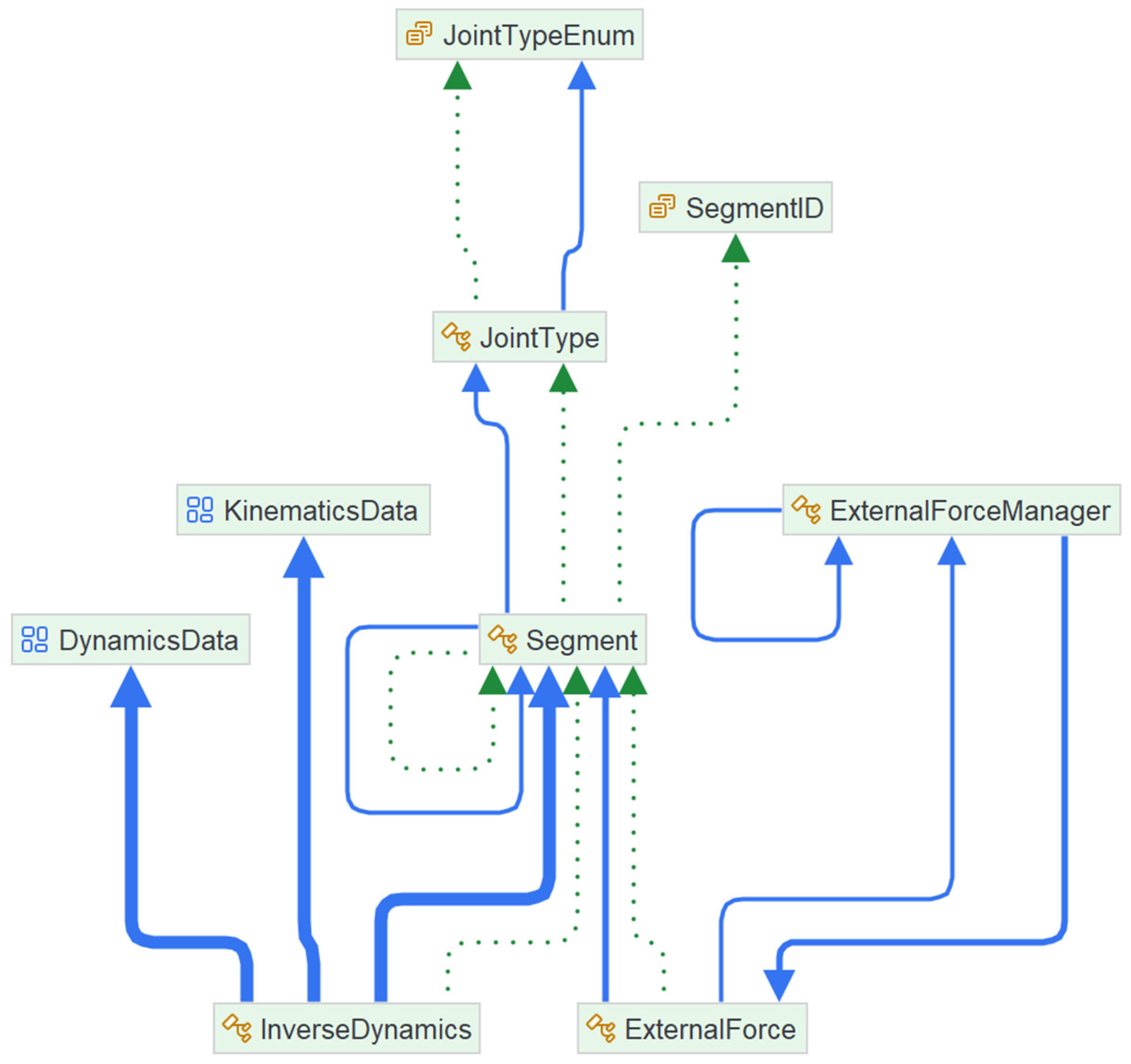
During each update cycle, segment states are refreshed from the current frame, a forward recursion computes the kinematic quantities, and a backward recursion accumulates the corresponding forces and torques. The resulting values are stored in per-segment dynamic data structures and passed to the recording and assessment modules. This modular architecture preserves a clear separation between planning, dynamics, and assessment while maintaining synchronized execution across the subsystem, as summarized in the accompanying type dependency diagram (
Figure 7).
Figure 7 illustrates the separation-of-kinematics-and-dynamics principle described in
Section 3.1: the inverse dynamics module operates exclusively on precomputed, frame-based kinematic data, with no direct coupling to the planning or gait-generation logic. This decoupling allows alternative inverse dynamics formulations or external force models to be introduced independently of the planning layer, as discussed in
Section 3.5.
5.9. Design Trade-Offs and Determinism
The smoothing process introduces controlled temporal filtering: excessive filtering risks damping genuine dynamic features, whereas insufficient filtering allows numerical instability to persist. Parameter selection must therefore balance numerical robustness, fidelity of motion representation, and computational efficiency. Because the system stores complete motion trajectories and relies on deterministic replay, the resulting force profiles remain reproducible and are well suited for identifying peak joint loading events, comparing estimated loads with biomechanical literature values, detecting instances of excessive mechanical demand, and supporting evidence-based accessibility assessment. By combining deterministic kinematic generation, structured external force integration, and stabilized inverse dynamics computation, the framework provides a reliable, analytically robust foundation for quantitative biomechanical evaluation.
5.10. Smoothing Coefficient Selection Rationale
Unlike the outlier-rejection threshold evaluated in
Section 6.7, the EMA smoothing coefficient α is not selected to optimize agreement with external reference data. Its role is to remove non-physiological, high-frequency force spikes introduced by sub-frame positional and rotational jitter in the recorded motion, which, left unfiltered, propagate through the derivative-based inverse dynamics computation and produce transient forces an order of magnitude above physiologically plausible values. The coefficient was selected empirically through repeated-run consistency testing: each of the three evaluation scenarios was executed multiple times under identical inputs at several candidate values of α, and the standard deviation of the resulting peak knee force across repeated runs was used as the selection criterion, rather than agreement with any single external reference value. α = 0.7 produced the lowest run-to-run deviation across all three scenarios and was adopted as the operating value for all subsequent results reported in this work. Once selected, α is held fixed, and the deterministic, frame-based architecture (
Section 5.7) ensures the resulting force profiles are reproducible across repeated executions of an identical scenario. The subsequent comparison results (
Section 6) should therefore be read as evidence of two distinct, complementary properties: reliability, meaning the pipeline no longer produces spurious jitter-driven force spikes, and consistency, meaning identical scenarios yield identical, low-variance output. Combined, these properties establish the simulation as a trustworthy measurement instrument for comparative accessibility assessment.
6. Validation and Verification
The objective of the validation process is to assess whether the proposed kinematic planning and inverse dynamics framework produces biomechanically plausible results under controlled conditions. Because the system estimates joint forces during simulated tasks, validation focuses primarily on comparing simulated joint loading patterns with established findings from the biomechanics literature. Rather than attempting full physiological validation, which would require subject-specific musculoskeletal modeling and experimental motion capture, the present evaluation examines whether the magnitude and temporal distribution of computed joint forces fall within expected ranges for common daily activities.
Figure 8 summarizes the overall validation workflow.
6.1. Validation Strategy & Assessment Methodology
The validation process follows a structured four-stage approach. First, representative locomotion scenarios are selected for which reliable biomechanical reference data exist in the literature. Second, kinematic trajectories are generated using the proposed planning framework. Third, inverse dynamics are executed to compute joint forces along the simulated trajectory. Fourth, simulated force magnitudes and timing are compared against published in vivo measurements.
The knee joint was selected as the primary validation reference for three reasons. Extensive literature exists on knee loading during walking and stair negotiation, providing well-established quantitative benchmarks. Knee forces are also sensitive to both inertial and ground reaction contributions, making them a rigorous test of the full inverse dynamics pipeline. Finally, the peak loading phases (heel strike and toe-off) are well documented, enabling both temporal and magnitude-based comparison.
In our assessment strategy, we define accessibility feasibility for a given task/environment configuration as a threshold check. The simulated peak joint force is compared against the maximum force the modeled user can sustain at that joint, drawn from the user’s capacity profile rather than from a single universal limit. If the simulated force exceeds this capacity threshold, the configuration is classified as a failed trial for that user profile; if it remains below threshold, the task is classified as feasible. This formulation deliberately ties the pass/fail criterion to the user model rather than to the environment alone, so that the same stair geometry can be feasible for one user profile and infeasible for another, consistent with the framework’s premise that accessibility is a property of the user-task-environment interaction.
In addition to the instantaneous threshold check, the framework monitors sustained sub-threshold loading using the recorded per-frame force data (
Section 5.6.1). If a joint’s force remains within a configurable margin below its capacity threshold for a prolonged portion of the task duration, the trial is flagged with a fatigue warning rather than a hard failure. This captures configurations that are not momentarily overloading but may be fatiguing over sustained or repeated use, a distinction relevant to accessibility, where discomfort and cumulative fatigue are barriers in their own right, separate from acute overload. We report this explicitly as a warning-level, exploratory indicator rather than a validated fatigue model: it has not been evaluated against fatigue or exertion data, and its purpose at this stage is to surface configurations worth closer review rather than to make a quantified fatigue claim.
The present implementation validates the simulation pipeline itself, its numerical reliability (
Section 5.10) and reproducibility (
Section 6.7), using a generic virtual human model, deliberately isolating pipeline correctness from user-specific variability. We do not claim the framework has been validated for diverse users; rather, we claim that the underlying motion-generation and force-estimation pipeline is reliable and consistent, which is a precondition for trustworthy diverse-user assessment. Extending coverage to diverse physical capabilities is, by design, a matter of correctly parameterizing user-specific gait characteristics and joint-capacity thresholds (
Section 6.8) within the existing gait-abstraction architecture (
Section 4), rather than re-validating or re-engineering the simulation pipeline. Populating these parameters with representative data for specific target populations is identified as future work (
Section 7.3).
6.2. Validation Scenarios
Three locomotion scenarios were implemented: normal walking, stair ascent, and stair descent. Each scenario consisted of a single navigation step with the underlying task of reaching a predefined waypoint; no additional interaction tasks were included in order to isolate locomotion mechanics from upper-limb behavior.
For each scenario, the kinematic planning subsystem generated step sequences along the navigation path, instantiating the appropriate gaits to produce deterministic foot and limb trajectories. The resulting motion was recorded, smoothed, and replayed, with inverse dynamics computations performed during playback. This controlled configuration ensured that observed force patterns could be attributed unambiguously to locomotion dynamics.
6.3. Validation Scenarios Setup Process
The validation scenarios were configured directly through the simulation user interface, ensuring that the test procedure could be reproduced without modifying the underlying source code. The interface-driven workflow also provides a consistent sequence for selecting the user representation, defining the environmental context, registering the simulation action, and executing the resulting scenario.
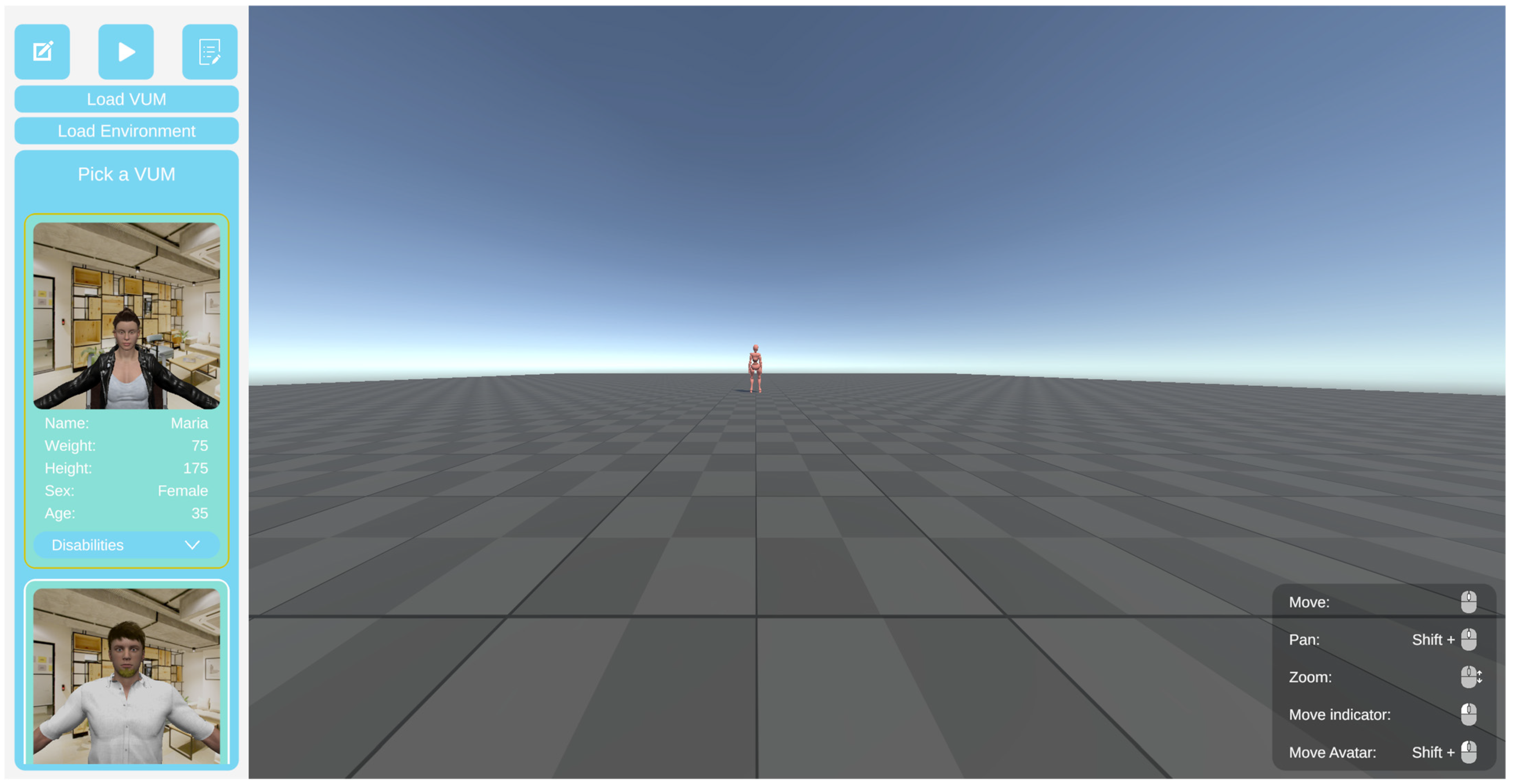
First, the appropriate virtual human model is selected, defining the anthropometric and functional user profile used by the kinematic planner and inverse dynamics pipeline during the simulation (see
Figure 9).
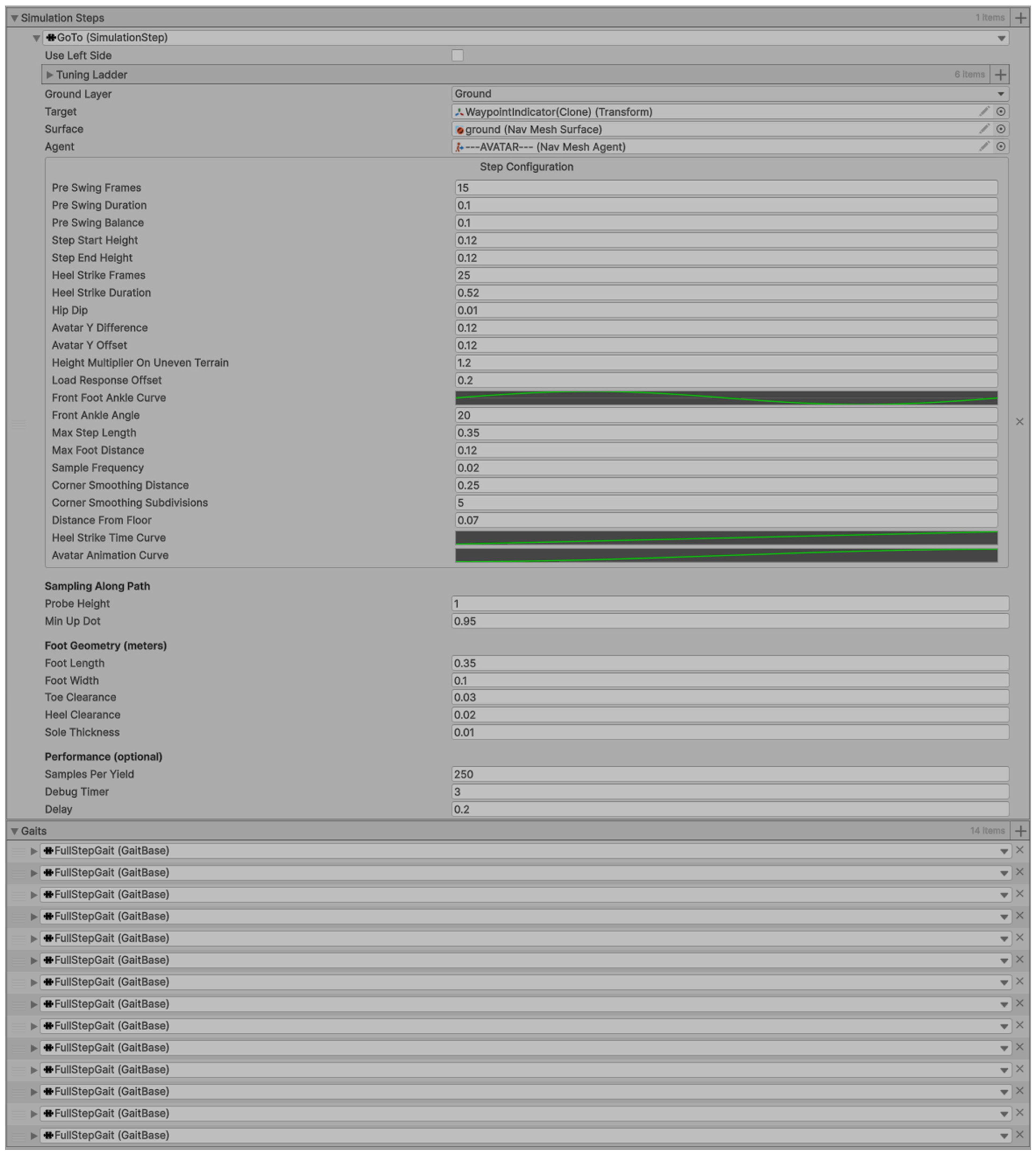
Second, a simulation step is added to the configured scenario (see
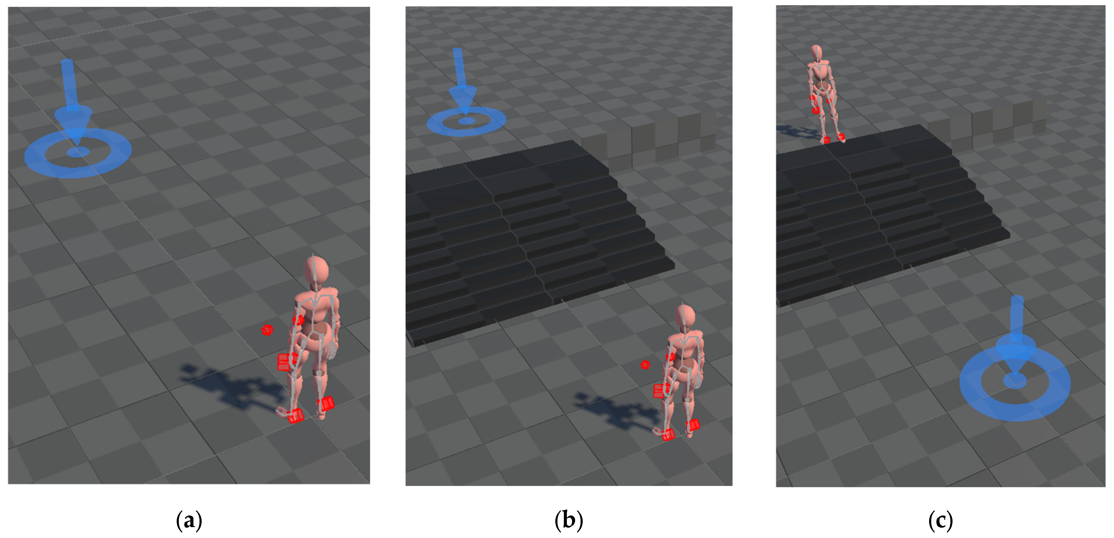
Figure 10). For the validation scenarios, this process is repeated three times, once for each scenario. All scenarios require a single “GoTo” simulation step. The following figure presents the scenarios in the 3D environment.
Finally, the simulation is started from the interface (see
Figure 11). During execution, the generated motion is replayed using the fixed-timestep simulation loop, and the resulting kinematic and dynamic outputs are recorded for subsequent analysis.
6.4. Reference Biomechanical Data
Literature on knee joint loading during walking indicates that peak joint forces typically range between approximately 1.0 and 3.5 times body weight, depending on walking speed and subject-specific gait characteristics [
29,
30]. For stair negotiation, reported peak forces are generally higher, ranging from approximately 2.5 to 4.0 times body weight for ascent and descent combined, reflecting the increased mechanical demand of elevation change [
31,
32]. Peak loading events are consistently observed at two phases of the gait cycle: heel strike, corresponding to the initial contact phase, and toe-off, corresponding to terminal stance. These reference values provide both quantitative and qualitative benchmarks against which the simulated outputs are assessed.
6.5. Kinematic Output Verification
Before analyzing dynamic results, the generated kinematic trajectories were inspected to verify the correctness of the motion plan. The reference values used for comparison [
30,
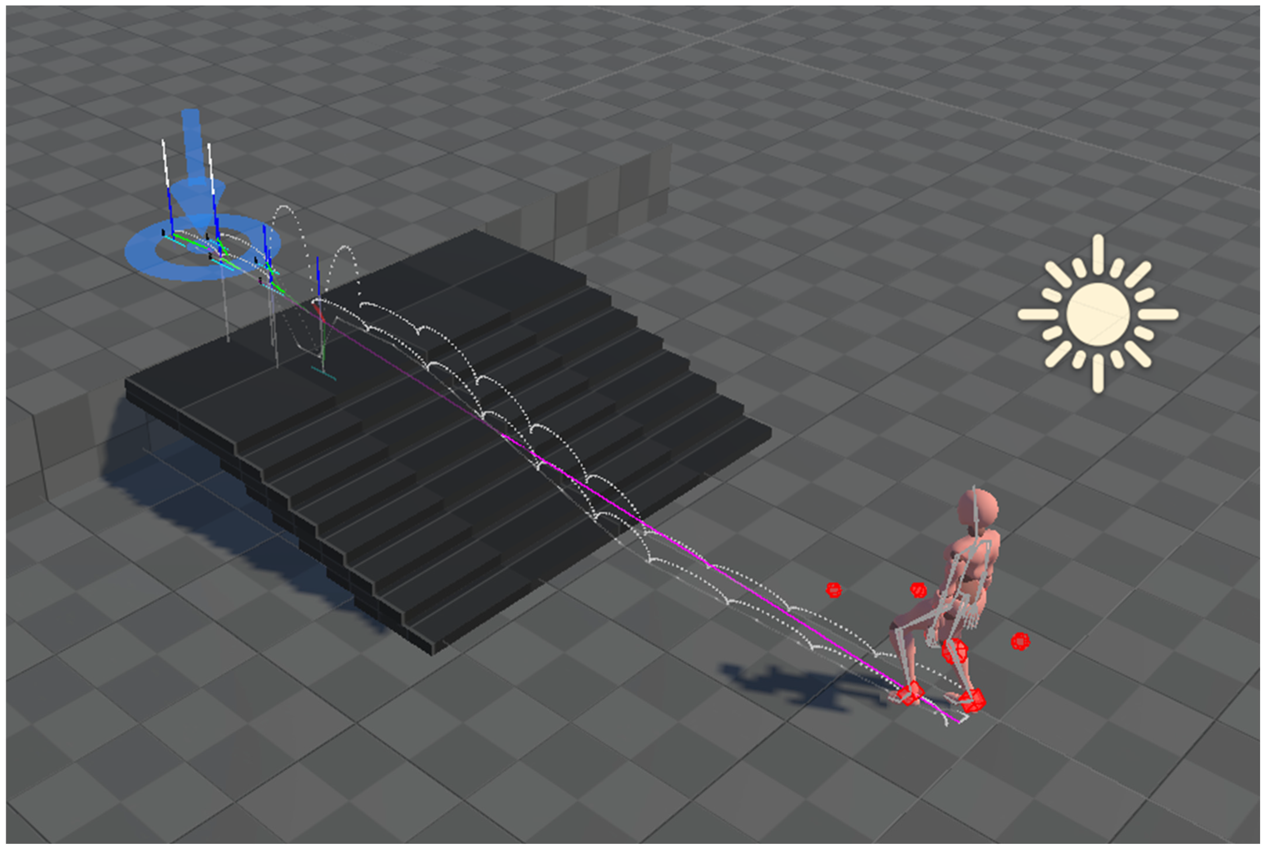
31] originate from the OrthoLoad dataset, an instrumented knee-implant benchmark collected in vivo and made publicly available specifically to support validation of biomechanical models and simulations, which partially mitigates concerns about relying on non-experimental reference values; though it remains a literature comparison rather than a matched, subject-specific experimental trial. The inspection confirmed proper sequencing of FullStepGait instances along the navigation path, correct spatial alignment between foot placements and computed waypoints, consistent step length and cadence, and smooth transitions between stance and swing phases. The frame-based trajectory representation allowed step-by-step examination of the generated motion, and the temporal structure of gait cycles was found consistent with expected walking patterns, including alternating stance phases and symmetric limb movement. The kinematic plan output for the three scenarios is shown in
Figure 12.
6.6. Dynamic Results
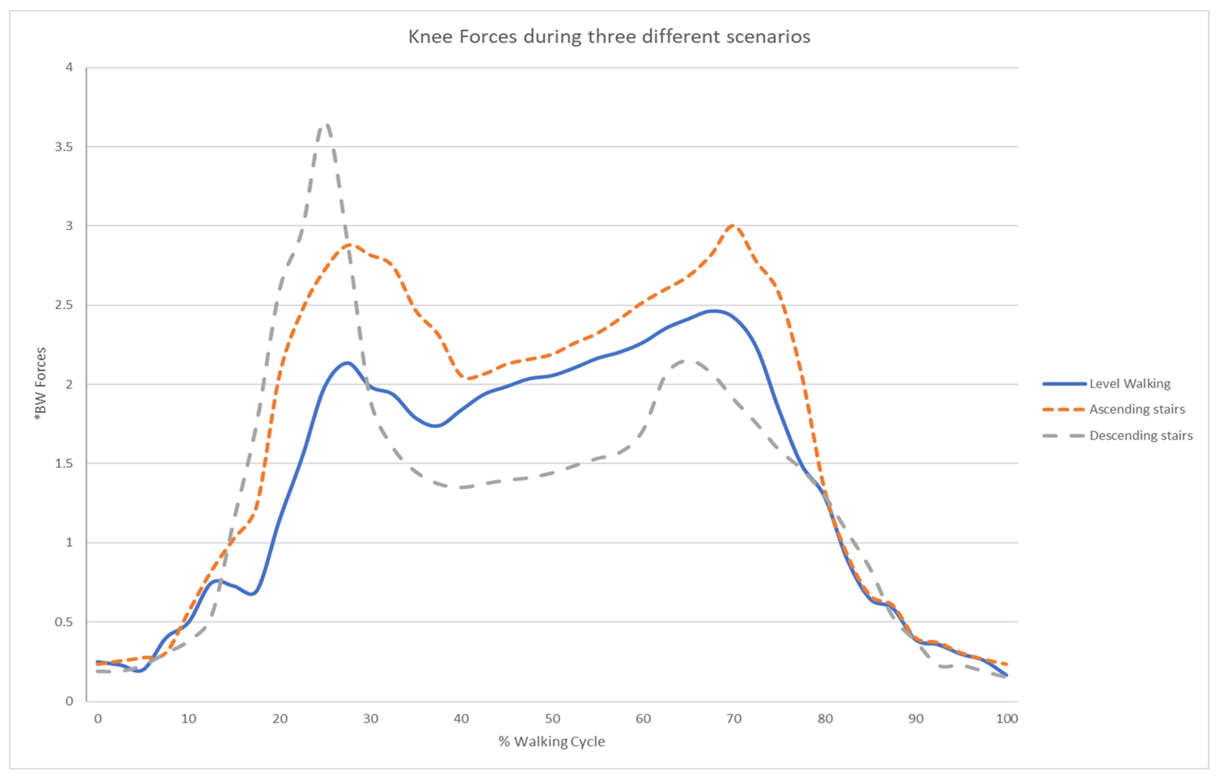
During execution, the inverse dynamics module computed forces and torques for all skeletal segments; for validation purposes, emphasis was placed on knee joint reaction forces. The simulated profiles are shown in
Figure 13.
The results demonstrated biomechanically consistent behavior across all three scenarios. For level walking, peak knee forces fell within the 1.0–3.5 times body-weight range reported in the literature, with clear force peaks corresponding to the heel strike and toe-off phases of each gait cycle. Stair ascent produced higher peak forces than level walking, consistent with the increased mechanical demand of elevation gain, while stair descent exhibited a distinct loading pattern with a pronounced peak during the weight-acceptance phase of each descending step. In all cases, force magnitudes scaled proportionally with task difficulty, and no unrealistic force spikes were observed in the smoothed output. The temporal alignment of peak forces with expected gait phases qualitatively matched documented biomechanical patterns across all scenarios.
These results are consistent with the conclusion that the inverse dynamics formulation, combined with the procedural kinematic planning framework, produces force estimates that fall within the magnitude and temporal ranges reported in the in-vivo biomechanics literature, rather than matching subject-specific experimental measurements.
To move beyond a qualitative range check,
Table 2 reports the simulated peak knee joint force obtained for each of the three scenarios alongside the corresponding in vivo reference value reported by Kutzner et al. [
30], together with the percentage difference between the two.
As shown in
Table 2, simulated peak knee forces differed from the reference values by −5.7% (level walking), −5.1% (stair ascent), and +5.5% (stair descent), with all three scenarios remaining within approximately ±6% of the corresponding in vivo measurement. Both magnitude and the expected ordering of task demand (level walking < stair ascent < stair descent) were preserved, supporting the reliability of the framework’s force estimates.
6.7. Reproducibility
Because the system relies on deterministic frame playback and fixed-timestep dynamics, results are fully reproducible across repeated simulation runs. Identical scenarios yield identical motion trajectories and constant force profiles, enabling controlled comparative analysis without variability introduced by real-time solver conditions. This property is particularly valuable for accessibility assessment workflows, where reproducibility is a prerequisite for meaningful comparison across environment configurations, gait strategies, or user profiles. It also supports systematic sensitivity analysis of smoothing parameters, allowing the effect of trajectory filtering on force estimates to be quantified independently of motion variability.
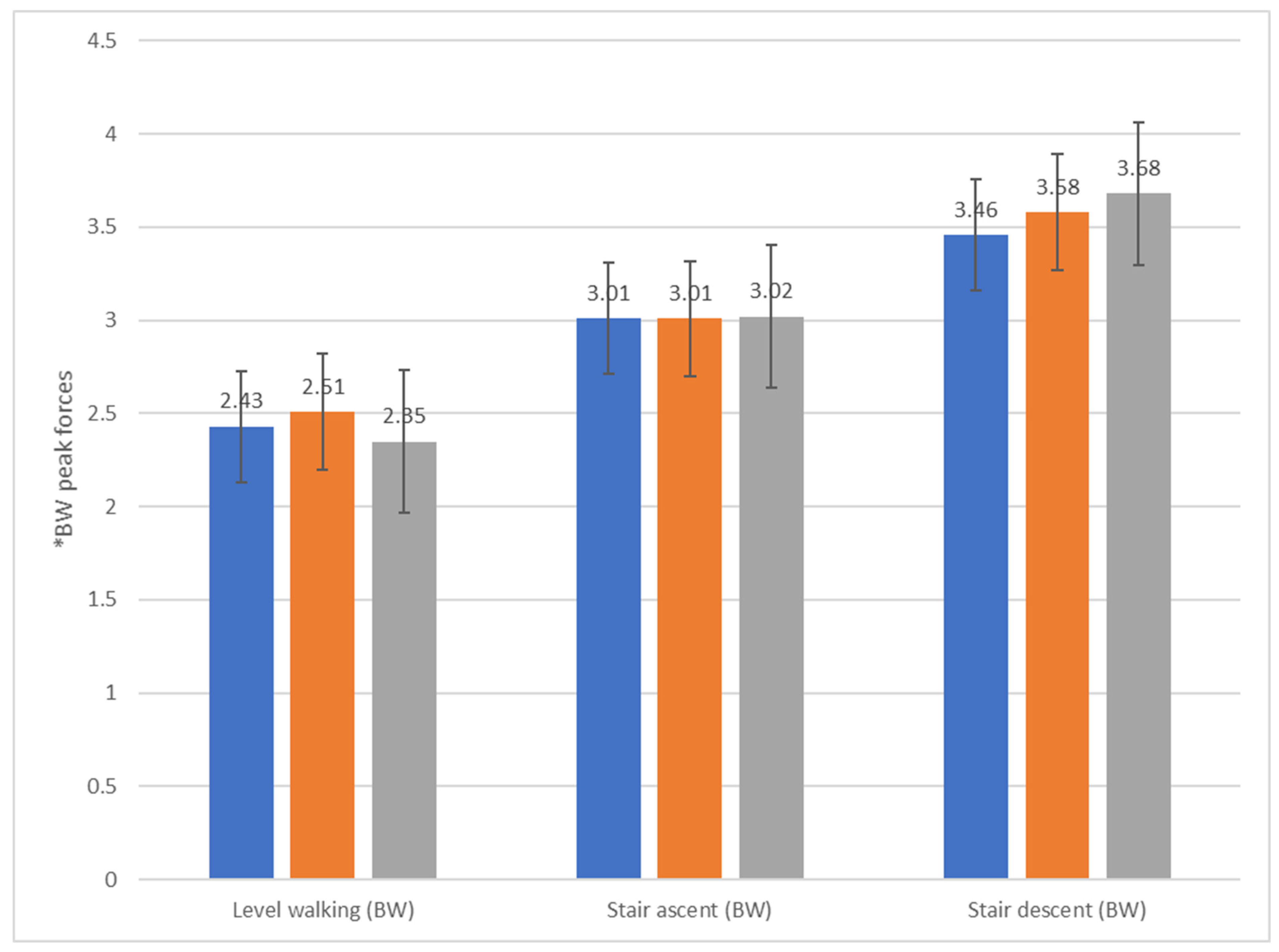
To evaluate whether the reported force patterns generalize beyond a single body type, the three scenarios (level walking, stair ascent, stair descent) were additionally executed for three user profiles differing in body mass (80 kg, 100 kg, and 120 kg, same virtual user model otherwise), and peak knee joint force was extracted from the recorded per-frame force data using the spike-removal procedure described in
Table 3;
Figure 14 summarize the results.
While the consistency of loading trends across scenarios and user profiles suggests that the underlying force-estimation approach is not scenario-specific, generalization beyond the tested locomotion tasks, standard stair geometry, and level-ground conditions should be interpreted with caution. Ramps, uneven terrain, use of assistive devices, and non-locomotor tasks such as reaching or transferring were not evaluated in the present study and constitute important directions for future work.
6.8. Sensitivity Analysis
To assess the robustness of the reported force estimates against measurement noise, the sensitivity of peak knee joint force to the spike-removal threshold was evaluated using the raw per-frame force recordings from the nine available simulation runs (three body-weight configurations × three locomotion scenarios). Isolated, non-physiological force spikes were identified using a Hampel identifier (5-sample rolling window), which flags samples deviating from the local median by more than k scaled median absolute deviations; flagged samples were replaced by interpolation and the resulting series was smoothed with a 3-sample moving average.
Table 4 reports the resulting peak knee force for each scenario/profile combination at three outlier-sensitivity settings (k = 2, 3, and 4). Across all nine scenario/profile combinations, peak force estimates varied by 3.7% on average (range: 0.0–7.3%) across the tested threshold values, indicating that the reported peaks are not an artifact of a specific spike-filtering choice.
It should be noted that the present validation compares simulated force magnitudes and timing against literature-reported reference data rather than against subject-specific, synchronously collected motion-capture and force-plate measurements for the same virtual scenarios. This approach is consistent with common practice for early-stage validation of biomechanical simulation frameworks, but a stronger validation in future work would involve direct comparison against experimentally collected kinematic and kinetic data for the same tasks. Furthermore, to evaluate the influence of smoothing on force estimates, peak knee force was recomputed for α = 0.1, 0.3, 0.5, 0.7 and 0.9 across the three scenarios (
Table 5).
Table 5 reports the standard deviation of peak knee joint force across N repeated executions of each validation scenario at five candidate values of α. Expressed as coefficient of variation relative to the mean peak forces reported in
Table 3, deviation was highest at low α (approximately 11–12% at α = 0.1), where insufficiently filtered jitter still propagates into the force estimate; deviation decreased steadily as α increased, reaching a minimum at α = 0.7 (approximately 1.2–1.4%); and increased again at α = 0.9 (approximately 4–5%), where reduced filtering once more allows residual signal noise through. This non-monotonic pattern is consistent across all three scenarios, supporting α = 0.7 as a stable, scenario-independent operating point rather than a value fitted to a single case.
7. Conclusions and Future Work
This work presented a modular simulation framework for accessibility-oriented virtual human evaluation, designed to move beyond static compliance-based assessment toward a dynamic, performance-based understanding of how built environments are experienced by users. By integrating task-driven kinematic planning with inverse dynamics analysis, the proposed system enables the simulation of human interaction with architectural spaces and the quantification of the mechanical demands. The framework was implemented in Unity and compared against literature-reported biomechanical reference ranges across three representative locomotion scenarios, yielding force estimates that fall within the magnitude ranges reported for in vivo measurements in the literature.
From an accessibility perspective, the framework contributes to a shift in how environments can be evaluated during the design process. Rather than treating accessibility as a checklist of geometric requirements, the proposed approach models accessibility as a function of task feasibility, physical effort, and movement stability. This allows designers and researchers to identify barriers not visible through conventional methods, such as excessive joint loading during reaching tasks, increased mechanical demand during stair negotiation, or instability arising from constrained spatial configurations.
The deterministic and reproducible nature of the simulation further supports comparative analysis across design alternatives. Different layouts, object placements, or circulation strategies can be evaluated not only for compliance, but also for their impact on user effort and physical demand. In this sense, the framework provides a foundation for evidence-based accessibility design, where decisions can be informed by quantitative measures of human performance rather than solely by prescriptive standards.
Comparison results indicate that the system produces biomechanically plausible joint loading patterns for representative locomotion tasks, including walking and stair negotiation. Peak joint forces align with expected ranges reported in the literature, and their temporal distribution corresponds to known gait phases. Specifically, simulated knee forces during level walking fell within the 1.0–3.5 body weight range consistent with in vivo reference data, while stair negotiation produced higher peak forces in the 2.5–4.0 body weight range, reflecting the increased mechanical demand of elevation change [
29,
30]. While the framework does not aim to replicate detailed musculoskeletal models, the current results indicate that it can provide stable, biomechanically interpretable estimates suitable for comparative accessibility assessment within the scope of the evaluated scenarios.
7.1. Contributions
The primary contributions of this work are summarized below, positioned in terms of their relevance to the broader goal of performance-based accessibility evaluation:
A task-driven simulation framework enabling performance-based assessment of accessibility, capturing how users interact with environments rather than relying solely on geometric compliance;
A modular kinematic planning architecture that supports context-aware motion generation for navigation and interaction tasks;
A deterministic, frame-based representation enabling reproducible evaluation of accessibility scenarios;
An integrated inverse dynamics module providing quantitative measures of biomechanical demand, including joint forces and torques during task execution;
A stabilization pipeline that ensures robust interpretable force estimation, supporting meaningful comparison across design alternatives.
Collectively, these contributions establish a foundation for incorporating dynamic human performance metrics into accessibility assessment workflows.
7.2. Limitations
The evaluation reported in
Section 6 covers level walking and stair negotiation using a generic anthropometric avatar. The WalkerGait module supporting assisted locomotion is implemented but not yet evaluated against reference data. Disability-specific gait variations (e.g., hemiparetic gait, prosthetic use) and reaching/transfer tasks are supported by the modular gait architecture (
Section 4.3) but remain untested and are prioritized as future work (
Section 7.3).
The present framework should be interpreted in light of several additional limitations. First, the biomechanical model is based on a rigid-body inverse dynamics formulation and therefore estimates net joint forces and torques rather than detailed muscle activations, tendon behavior, or subject-specific musculoskeletal responses. As a result, the computed loads should be understood as comparative indicators of mechanical demand rather than fully physiological predictions for individual users.
Second, external force modeling is simplified. Ground reaction forces and other environmental contacts are introduced through rule-based force application within the External Force Manager, rather than through experimentally measured force plates, high-fidelity contact models, or subject-calibrated interaction data. This design supports stable, reproducible simulation, but may reduce accuracy during complex contact conditions, including transitional gait phases, multi-contact interactions, or tasks involving assistive devices and irregular support strategies.
Third, the current evaluation is limited in scope. It focuses on representative locomotion scenarios, namely level walking, stair ascent, and stair descent, and compares the resulting knee loading patterns with reference values reported in the biomechanics literature. While this provides an important first indication of plausibility, it does not constitute full experimental validation against motion-capture, force-plate, or in vivo subject data acquired under matched conditions.
Fourth, the present implementation relies on a generic avatar configuration and does not yet account for inter-individual variability in anthropometry, strength, joint mobility, age-related decline, or disability-specific movement strategies. Since accessibility assessment is inherently user-dependent, broader representation of diverse body types and functional capabilities will be necessary to support population-specific or personalized analysis.
Finally, the current scenario set emphasizes locomotion and basic task sequencing, whereas many accessibility barriers emerge during richer interaction tasks such as seated reach, transfer movements, door manipulation, support-based locomotion, and navigation in highly constrained spaces. Extending the framework toward these use cases, together with more detailed contact modeling and empirical validation, is an important direction for future work.
7.3. Future Work
Future research can extend the framework along several complementary axes. From a biomechanical modeling perspective, enhanced contact modeling through more detailed force estimation methods could improve ground reaction force fidelity, particularly during complex multi-contact interactions. Expanding the dynamic analysis to account for fatigue accumulation and sustained loading would strengthen assessment of prolonged or repetitive tasks, particularly relevant for workplace and residential accessibility. Incorporating simplified muscle-force estimation, even through static optimization approaches, would also provide more physiologically meaningful load indicators for populations with reduced strength or altered neuromuscular control.
From a motion generation perspective, an expanded gait library (including adaptive stepping strategies, assistive device use, and mobility-impaired locomotion patterns) would broaden scenario coverage and enable more inclusive evaluation. Incorporating motion capture data from users with specific disabilities could further ground simulated trajectories in observed behavior, improving both the realism and the clinical relevance of the generated motion.
From a validation perspective, conducting quantitative sensitivity analyses of smoothing parameters, timestep resolution, and external force modeling assumptions would strengthen confidence in dynamic outputs. Experimental validation against motion-capture and force-plate data acquired under matched conditions remains the most important next step for establishing the framework’s accuracy beyond the plausibility benchmarks demonstrated here.
From an application and integration perspective, coupling the framework with design optimization workflows could enable automatic identification of environmental configurations that minimize biomechanical demand, supporting iterative, performance-driven accessibility design. Integration with BIM authoring environments would further reduce the barrier to adoption by enabling accessibility simulation directly within existing architectural modeling pipelines. Ultimately, the goal is to provide architects, planners, and accessibility specialists with a practical, evidence-based tool that makes the physical consequences of design decisions visible before construction begins.




 ,
,