Article

Regulating the Electronic State of Ruthenium via a Support Facet Structure for the Efficient Selective Hydrogenation of Benzene

1
Coal Chemical R&D Center of Kailuan Group, Tangshan 063018, China
2
Hebei Provincial Technology Innovation Centre of Coal-Based Materials and Chemicals, Tangshan 063018, China
3
School of Environmental and Chemical Engineering, Yanshan University, Qinhuangdao 066004, China
4
Faculty of Engineering, Kanagawa University, Yokohama 221-8686, Japan
*
Author to whom correspondence should be addressed.
Appl. Sci. 2026, 16(15), 7453; https://doi.org/10.3390/app16157453
Submission received: 20 June 2026 / Revised: 22 July 2026 / Accepted: 22 July 2026 / Published: 25 July 2026
(This article belongs to the Section Chemical and Molecular Sciences)

Abstract

Ruthenium-based catalysts have attracted considerable attention owing to their excellent activity in the selective hydrogenation of benzene to cyclohexene. Their catalytic performance is primarily governed by the electronic structure of metallic active sites and the interfacial interaction between the metal and the support. In this work, three types of TiO2 support, including nanosheet flowers (TNSFs), elongated bipyramids (TNEBs), and tetragonal bipyramids (TNQBs), were successfully synthesized via a solvothermal route, which predominantly expose the (001), (010), and (101) crystal facets, respectively. Subsequently, ruthenium nanoparticles were deposited onto the support surfaces by means of chemical reduction, yielding three supported catalysts. The exposed (101) crystal facets of TNQBs induce the strongest electronic metal–support interaction (EMSI). Abundant Ti3+ defects and oxygen-containing species on the surface endow the catalyst with superior hydrophilicity, enhancing the contact between the reaction medium and active sites as well as the desorption of cyclohexene. Meanwhile, the supported Ru species exhibit the highest fraction of electron-deficient states, with the proportion of Ruβ reaching up to 82.22%. As a result, the catalyst exhibits outstanding catalytic performance, achieving a benzene conversion of 42.8%, a cyclohexene selectivity of 82.27%, and a cyclohexene yield as high as 53.22%.

1. Introduction

The selective hydrogenation of benzene to cyclohexene is one of the most important catalytic reactions in the coal chemical industry. Cyclohexene serves as an important intermediate to produce bulk chemicals such as nylon 66 and adipic acid [1,2,3,4,5,6,7,8]. In recent years, the demand for cyclohexene has rapidly increased due to the rise of the biodegradable plastic industry [9,10]. The major industrial routes for cyclohexene production include the dehydration of cyclohexanol [11], the catalytic dehydrogenation of cyclohexane [12], the dehydrohalogenation of halogenated cyclohexanes [13], and the selective hydrogenation of benzene [14]. Among these approaches, the selective hydrogenation of benzene is regarded as the most attractive because of its mild reaction conditions, high atom economy, and environmental friendliness. The process of selective hydrogenation of benzene to cyclohexene mainly includes gas-phase hydrogenation, homogeneous complexation hydrogenation, and liquid-phase hydrogenation. Liquid-phase hydrogenation is carried out at relatively mild temperatures (100–180 °C) and medium pressures (3–6 MPa) using water as the medium and employs easily separable and recoverable heterogeneous supported catalysts. This process achieves an excellent balance between benzene conversion and cyclohexene selectivity through the optimization of catalyst surface properties and reaction conditions. Furthermore, its high operational controllability and excellent potential for industrial scale-up have made liquid-phase selective hydrogenation the dominant research direction and industrial technology in this field [15,16].
Early studies on the selective hydrogenation of benzene to cyclohexene mainly employed transition metal catalysts, including platinum, palladium, and nickel [17,18]. Since the late twentieth century, ruthenium-based catalysts have attracted extensive attention because of their outstanding activity and selectivity for the selective hydrogenation of benzene. In the 1990s, the Asahi Kasei Corporation (Japan) was the first to commercialize the selective hydrogenation of benzene to cyclohexene by establishing a production facility with an annual capacity of 60 kt. The industrial process consisted of the hydrogenation of benzene to cyclohexene followed by the hydration of cyclohexene to cyclohexanol. In 1996, the Shandong Hualu-Hengsheng Group in China introduced a similar production process, making China the second country to industrialize this technology. Since the 1990s, extensive studies have been carried out by research institutions, including the Chinese Academy of Sciences, the Dalian Institute of Chemical Physics, Fudan University, Zhengzhou University, and industrial enterprises such as the China National Petroleum Corporation [7,19,20,21]. Significant progress has been achieved in catalyst design, synthesis strategies, and mechanistic understanding [22]. For example, the Dalian Institute of Chemical Physics systematically investigated Ru–Zn bimetallic catalysts and elucidated the role of support effects in regulating metal dispersion. Fudan University reported significant advances in mesoporous-confined Ru nanoparticles and interfacial electronic interactions. Zhengzhou University developed Ru–M–B/ZrO2 catalysts that achieved cyclohexene yields approaching 50%, which were subsequently applied in industrial production [21,23]. These developments marked China’s transition from technology importation to independent technological innovation in this field. More recently, research has expanded to emerging catalyst systems, including two-dimensional materials, strong metal–support interactions, and atomically dispersed catalysts, with the aim of further improving cyclohexene selectivity and catalyst stability. However, cyclohexene is thermodynamically less stable than both benzene and cyclohexane and is therefore readily subjected to further hydrogenation to cyclohexane. Therefore, the key to achieving high cyclohexene selectivity lies in designing catalysts capable of precisely regulating the hydrogenation pathway while suppressing the undesired deep hydrogenation of cyclohexene.
The catalytic performance of ruthenium-based catalysts is mainly determined by the electronic structure of the metal active center and its interfacial interaction with the carrier. Electronic metal–support interaction (EMSI) is a key interface electronic effect that can significantly change the electronic density of metal nanoparticles through charge transfer from the carrier to the metal, affecting the adsorption strength of reactants and intermediates and the reaction pathway. Titanium dioxide (TiO2) is a classic EMSI carrier, with different exposed crystal planes having different surface atomic arrangements, electronic structures, and defect chemical properties. Shi [24] constructed Ru nanoparticles on MXene-derived three-dimensional porous TiO2 and utilized electronic metal–support interaction (EMSI) to regulate electron-deficient state of Ru. This study focuses on “the crystal plane dependence of Ru’s electronic state”, aiming to systematically reveal the intrinsic structure–activity relationship among the TiO2 carrier crystal plane structure, Ru’s electronic state, and catalytic performance.

2. Experiments

2.1. Main Reagents

Ti(SO4)2, C3H8O: Macklin reagent; C12H28O4Ti: Inokai Technology Co., Ltd. (Beijing, China); C4H13N3, C6H6, AgNO3, Cu(NO3)2·3H2O, Co(NO3)2·6H2O, MnCl2, Ni(NO3)2·6H2O, Na2B4O7·10H2O, La(NO3)3·6H2O, Ni(NO3)2·6H2O: Aladdin Reagent Co., Ltd. (Shanghai, China); C6H12, C6H10: Meredith Technology Co., Ltd. (Beijing, China); RuCl3·3H2O: Merrill Biochemical Technology Co., Ltd. (Shanghai, China); NaBH4, CH3CH2OH: Tianjin Compex Reagent Co., Ltd. (Tianjin, China); ZnSO4·7H2O: Bide Pharmaceutical Technology Co., Ltd. (Shanghai, China); NaOH: Tianjin Damao Chemical Reagent Factory (Tianjin, China); H2: Qinhuangdao Yuanxing Industry and Trade Co., Ltd. (Qinhuangdao, China).

2.2. Synthesis of Catalysts

2.2.1. Synthesis of Carriers TNSFs, TNEBs, and TNQBs

Synthesis of TNSFs: First, 42 mL of isopropanol was added to a beaker, and 0.03 mL of diethylenetriamine was slowly added using a pipette, followed by gentle stirring for 2 min to ensure complete mixture. Then, 1.5 mL of isopropyl titanate was added dropwise and stirred gently to ensure uniform dispersion. The mixture was transferred to a stainless-steel high-pressure reactor with a polytetrafluoroethylene inner lining and reacted at 200 °C for 24 h. After the reaction, the yellow precipitate was collected, washed three times with deionized water, and dried at 70 °C for 2 h. Finally, it was calcined at 400 °C in an air atmosphere for 2 h to obtain the TNSF sample.
Synthesis of TNEBs: First, 60 mL of deionized water was placed in a beaker, followed by the sequential addition of 0.72 g of Ti(SO4)2, 0.72 g of CH4N2O (urea), and 1.34 g of C10H14N2Na2O8 (EDTA disodium). The solution was stirred at 700 rpm until the solids completely dissolved to form a homogeneous solution. The solution was transferred to a stainless-steel high-pressure reactor with a polytetrafluoroethylene inner lining and subjected to a solvent thermal reaction at 180 °C for 10 h. After the reaction, the obtained white precipitate was collected, washed three times with deionized water, and then dried in a 70 °C oven for 5 h. Finally, it was calcined at 400 °C in an air atmosphere for 2 h to obtain the TNEB sample.
Synthesis of TNQBs: First, 60 mL of deionized water was placed in a beaker, followed by the sequential addition of 0.72 g of Ti(SO4)2 and 1.34 g of C10H14N2Na2O8 (EDTA disodium). The solution was stirred at 700 rpm to fully dissolve the solid substances, forming a homogeneous solution. The solution was transferred to a high-pressure reactor with a polytetrafluoroethylene inner lining and reacted at 180 °C for 10 h. After the reaction and cooling, the white precipitate obtained was separated, washed three times with deionized water, and then placed in a 70 °C oven for drying for 5 h. Finally, it was calcined at 400 °C in an air atmosphere for 2 h to obtain the TNQB sample.

2.2.2. Synthesis of Ru/TNSFs, Ru/TNEBs, and Ru/TNQBs

We dissolved 0.5 g of the synthesized TNSFs, TNEBs, and TNQBs in 20 mL of H2O. Then, we added 2.5 mL of RuCl3 aqueous solution (0.2 mol/L) and stirred for 1 h. Next, we added 2.5 mL of NaBH4 aqueous solution (0.8 mol/L) and continued stirring for another 1 h until the reaction was complete. The obtained precipitate was centrifuged and washed. The supernatant was tested with 0.1 mol/L AgNO3 solution until all chloride ions were completely removed. The precipitate was dried under vacuum to obtain the Ru/TNSF, Ru/TNEB, and Ru/TNQB catalysts. The theoretical loading of ruthenium in these catalysts was 10% wt.

2.3. Evaluation of Catalytic Performance for Partial Hydrogenation of Benzene to Cyclohexene

The evaluation of the liquid-phase benzene-selective hydrogenation performance of the catalyst was conducted in a 0.25 L stainless-steel high-pressure reactor. The specific operation was as follows: 0.5 g of the catalyst, 60 mL of deionized water, and 12 g of ZnSO4·7H2O were added to the reactor, while 30 mL of benzene was placed in the connected reactant storage tank. After sealing the system, the reactor and the storage tank were repeatedly purged with hydrogen gas 5 times to completely remove the air. Then, the temperature was raised to 140 °C at a rate of 5 °C/min, and a hydrogen pressure of 4.0 MPa and a stirring speed of 800 r/min were maintained for 4 h to allow the catalyst to achieve stable dispersion in the reaction medium.
After the pre-treatment was completed, the benzene in the storage tank was added to the reaction system immediately using a high-pressure metering pump (Jinhai Pump Industry. Botou, China), which was recorded as the start point of the reaction. The reaction conditions were adjusted as follows: hydrogen pressure of 5.0 MPa, stirring speed of 1000 r/min, and temperature maintained at 140 °C. From the start of the reaction, small amounts of oil-phase products were collected every 5 min through the built-in sampling valve. The samples were filtered through a membrane (Jinzheng Filter Material Technology Co., Ltd. Haining, China), and the content of benzene, cyclohexene, and cyclohexane was analyzed using a gas chromatograph equipped with an FID detector (PerkinElmer, Shanghai, China). The concentrations of each component were calculated using the corrected area normalization method, thereby obtaining the benzene conversion rate and the selectivity of cyclohexene.
To ensure the reliability of the data, all catalyst samples were subjected to at least two parallel tests, with the result deviation controlled within 2%.

3. Results and Discussion

3.1. The Formation Mechanism and Structural Characteristics of the Catalyst

3.1.1. The Formation Mechanism of Ru/TNSF, Ru/TNEB, and Ru/TNQB Catalysts

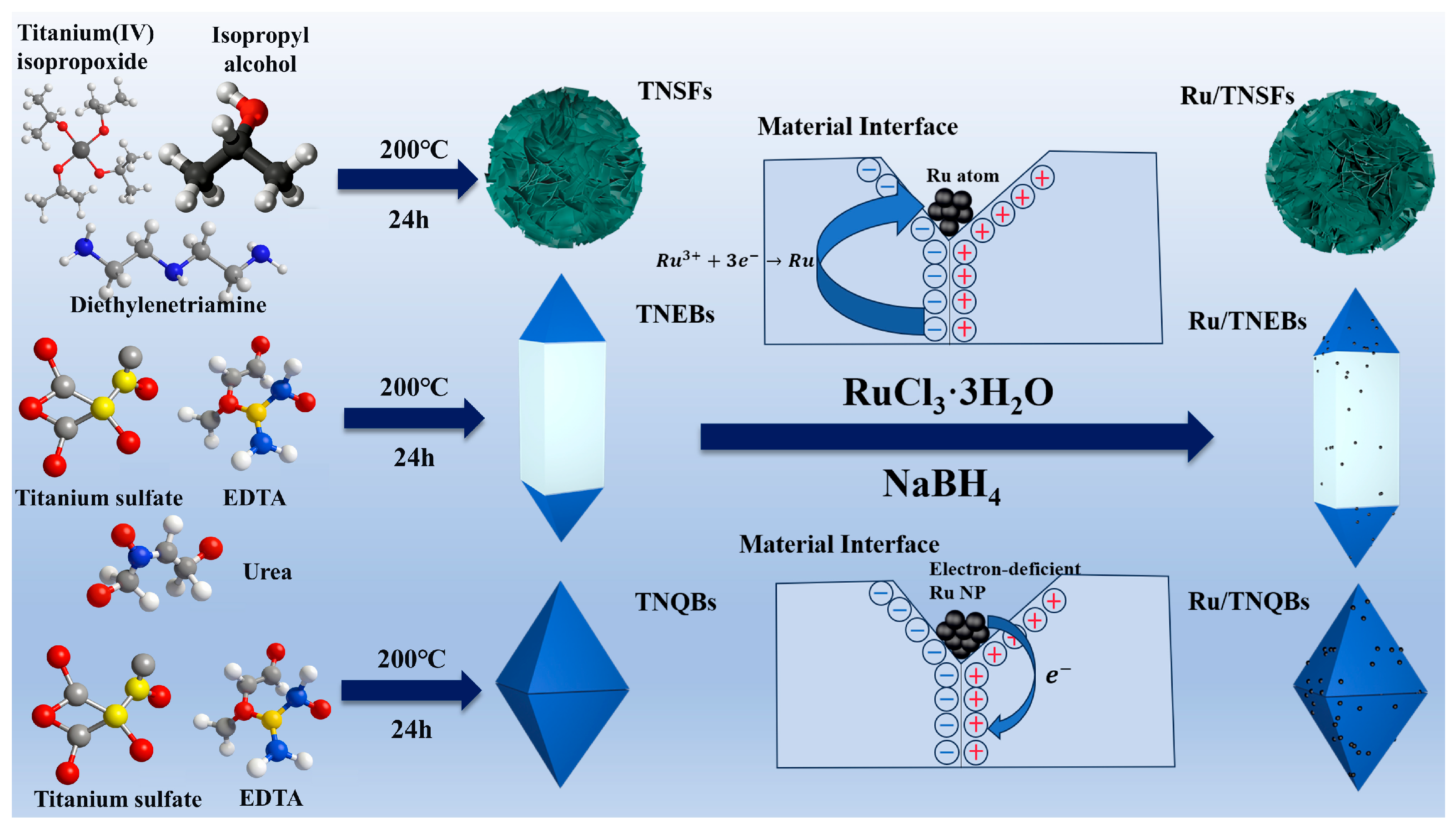
The synthesis processes and mechanisms of the Ru/TNSF, Ru/TNEB, and Ru/TNQB catalysts are shown in Figure 1.
Figure 1 presents the construction mechanism of the supported ruthenium catalytic material based on the electronic metal–support interaction (EMSI) [25,26]. The left side of the schematic diagram shows three titanium dioxide (TiO2) nano-carriers with differentiated crystal planes, namely nanosheet flower (TNSF), elongated bipyramid (TNEB), and quadripartite biconical (TQBC). Among them, nanosheet flower-shaped TiO2 (TNSF) uses isopropyl titanate as the titanium source, isopropanol as the solvent, and diethylenetriamine as the morphology-directing agent. It preferentially adsorbs on the (001) crystal plane of anatase TiO2, effectively reducing the surface energy of this crystal plane and hindering the stacking growth of the titanium precursor in its normal direction (001). This kinetic blockage forces the crystal growth to mainly proceed in the unsealed (010) and (100) directions, thereby inducing the formation of two-dimensional sheet-like units with the (001) plane as the upper and lower surfaces. These nanosheets further self-assemble to form three-dimensional flower-like aggregates. The elongated bipyramid-shaped TiO2 (TNEB) uses titanium sulfate as the titanium source, ethylenediaminetetraacetic acid disodium as the complexing agent, and urea as the precipitant. EDTA forms a stable complex with Ti4+ to control the release rate of titanium ions, and urea slowly releases ammonia during thermal decomposition to regulate the pH of the system, promoting TiO2 nucleation and growth; the EDTA residues selectively adsorb on the (101) crystal plane, regulating the relative growth rate of each crystal plane, forcing the crystal to extend in the [010] direction to form an elongated morphology. The tetragonal biconical morphology is due to the release of Ti4+ from titanium sulfate in water, first forming a six-atom chelate complex ([Ti-EDTA]0) with EDTA, effectively inhibiting the spontaneous precipitation of titanium ions; in the hydrothermal environment, the thermal dynamics drives the gradual dissociation of the complex, releasing Ti4+ through hydrolysis (Ti4+ + 4H2O → Ti(OH)4 + 4H+) and dehydration condensation (2Ti(OH)4 → [TiO6] octahedral unit), and orientally assembling into a titanium dioxide crystal nucleus of the anatase phase. The EDTA residues selectively adsorb on the high-energy {001} crystal plane (adsorption energy ≈ −1.8 eV), significantly inhibiting the growth rate of this plane (G{001}/G{101} ≈ 0.25), while the low-energy {101} plane freely extends, ultimately forcing the crystal to grow preferentially in the <101> direction to form the tetragonal biconical morphology. The unique crystal plane exposure characteristics of the three TiO2 carriers are attributed to the differences in the types of directing agents used in the synthesis system and their selective adsorption capabilities on specific crystal planes, thereby regulating the crystal plane growth kinetics.
When using RuCl3·3H2O as the ruthenium precursor, it undergoes hydrolysis at the TiO2–Ru interface, dissociating into [Ru(H2O)6]3+, which undergoes coordination anchoring with the titanium hydroxide (Ti-OH) through electrostatic attraction (forming Ti-O-Ru bonds), and is adsorbed by the reducing agent NaBH4 to provide electrons, driving the reduction reaction of Ru3+ (Ru3++3e → Ru), generating elemental ruthenium. During this process, the electrons captured by the carrier lattice defects (such as Ti3+) and provided by the external reducing agent synergistically participate in the interface electron transfer, inducing the EMSI effect and causing some ruthenium species to form electron-deficient ruthenium nanoparticles (electron-deficient Ru NP). The right side of the schematic diagram shows the final formed supported ruthenium catalyst, whose electronic state is regulated by the different crystal plane structures of the TiO2 carriers. The differences in atomic arrangement, electron density, and defect distribution of the carrier crystal planes collectively affect the direction and rate of electron transfer, thereby regulating the final electronic state of the ruthenium species (such as the relative proportion of Ruδ+), achieving effective coupling between the carrier structure and the metal’s electronic state.

3.1.2. Phase Analysis and Morphological Characterization of Ru/TNSF, Ru/TNEB, and Ru/TNQB Catalysts

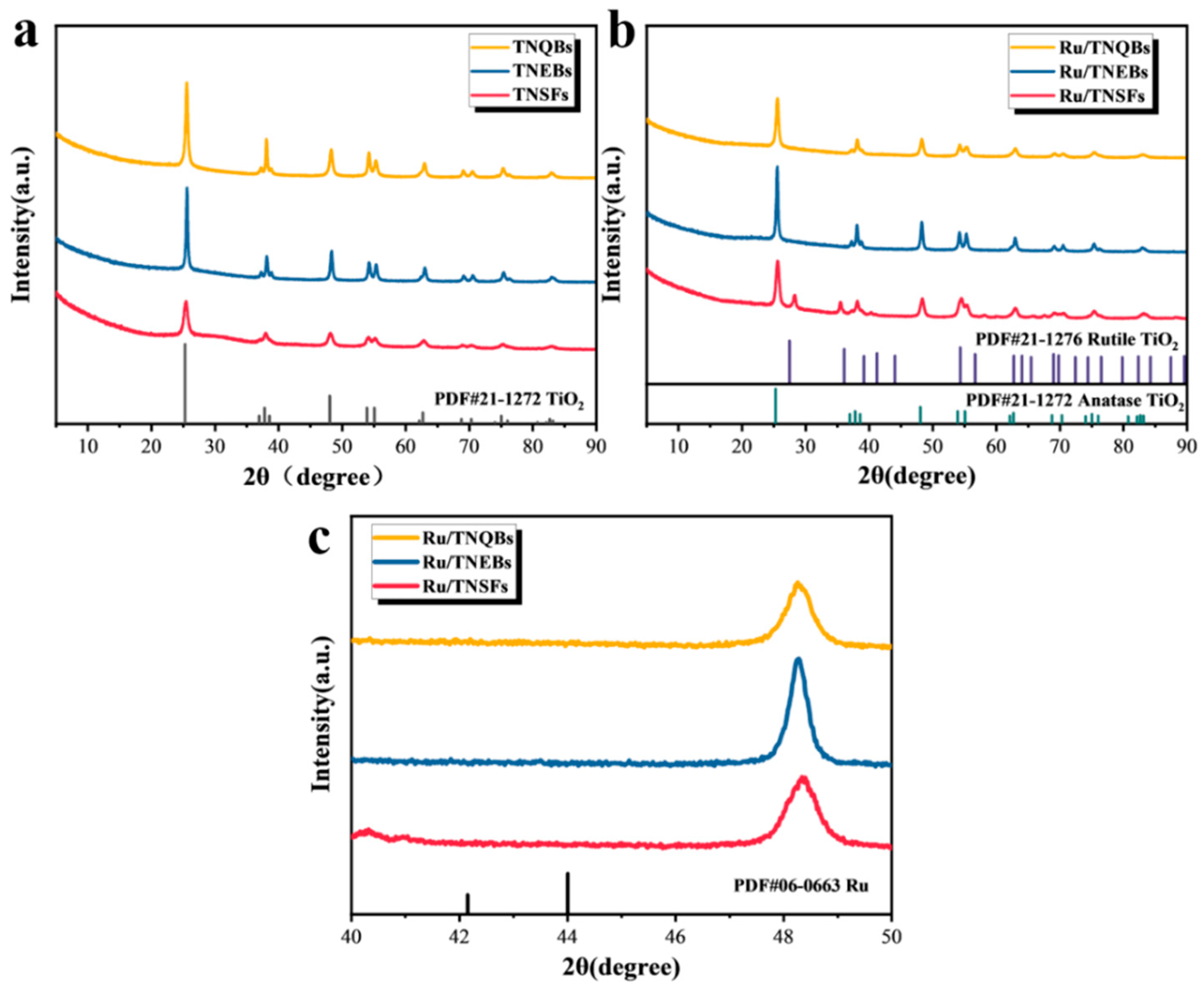
To conduct a detailed analysis of the structural characteristics of the catalyst samples, X-ray diffraction technology was employed to characterize their crystal structures. As shown in Figure 2a, the XRD spectra of different samples exhibited similar features. The XRD spectra of the TNSF, TNEB, and TNQB samples all showed obvious characteristic diffraction peaks at positions with 2θ values of 25.3°, 36.9°, 37.8°, 38.6°, and 48.0°, which were consistent with the standard card of anatase TiO2 (JCPDS #21-1272), indicating that the main crystalline phases of the three carrier materials were all anatase.
The corresponding Ru/TNSF, Ru/TNEB, and Ru/TNQB catalyst samples in Figure 2b also retained the main characteristic peaks of the anatase phase, without significant phase transformation. In addition, the Ru/TNSF sample observed characteristic diffraction peaks belonging to the rutile phase TiO2 (JCPDS #21-1276) at 2θ values of 27.4°, 36.1°, 41.2°, 54.3°, and 56.6°, indicating that there was a small amount of the rutile phase in the catalyst structure. In the XRD spectra of all catalysts, no obvious diffraction peaks of metallic Ru were observed. There could be two reasons for this: one is that the loading amount of Ru in the catalyst is low (10 wt%), and its diffraction signal is easily masked by the background peak of the carrier; the other is that the characteristic diffraction peaks of Ru usually appear in the range of 2θ = 40.0–45.0°, and this range was locally enlarged in this work. As shown in Figure 2c, no obvious Ru diffraction peaks were observed in the enlarged spectrum, indicating that Ru may be in a highly dispersed state on the TiO2 carrier surface, with a small grain size, resulting in a broadened or indistinct diffraction peak [27].
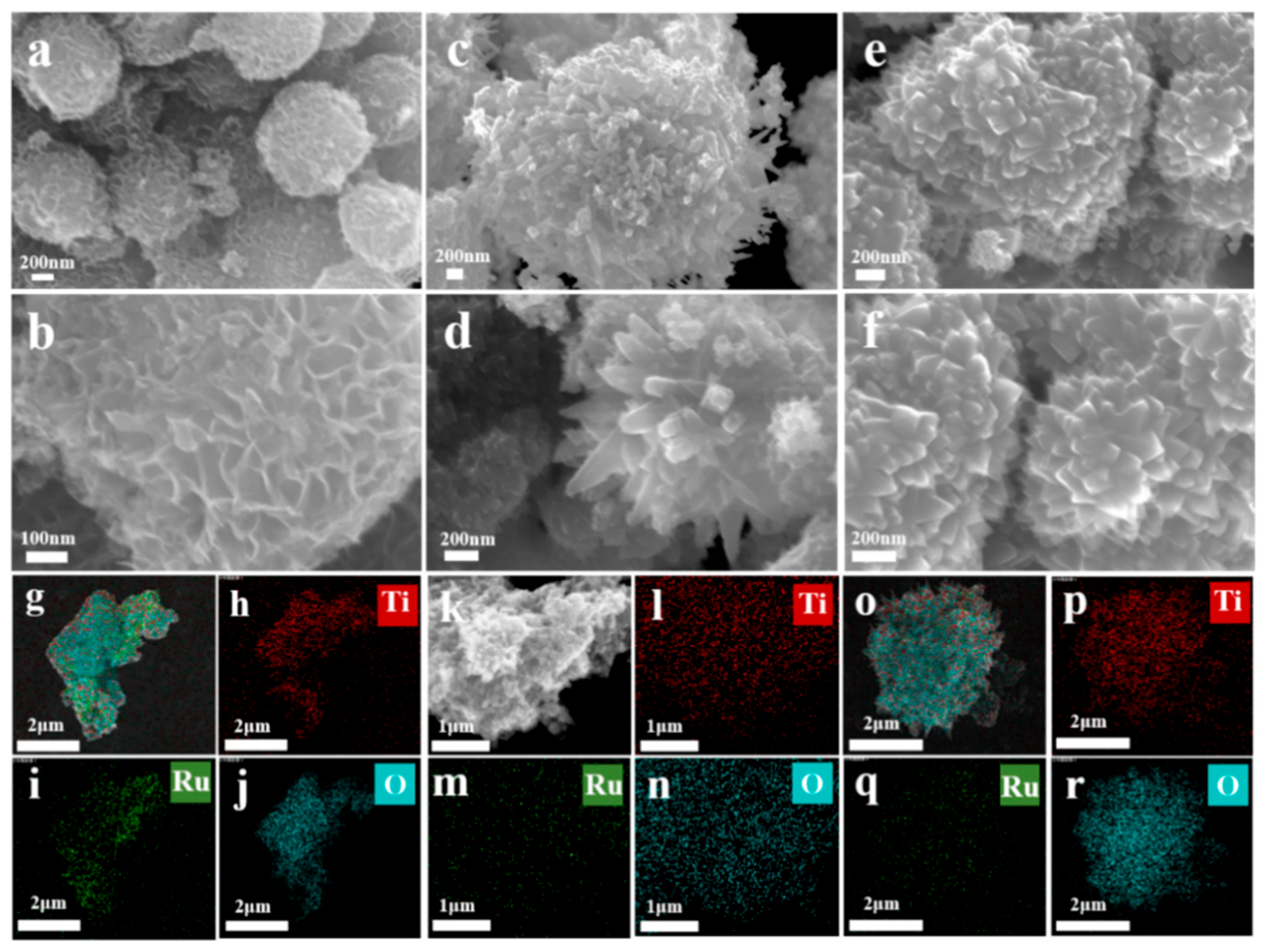
Figure 3 systematically characterizes the microstructure and elemental distribution of the three different morphologies of Ru-loaded TiO2 catalysts (Ru/TNSFs, Ru/TNEBs, and Ru/TNQBs) through scanning electron microscopy (SEM) and corresponding energy dispersive X-ray spectroscopy (EDS) surface scanning analysis. From left to right, the images correspond to nanosheet flower-like (Figure 3a,b), long prismatic (Figure 3c,d), and tetragonal double-prismatic (e,f) structures. Low-magnification SEM images (Figure 3a,c,e) show that all three carriers exhibit a clear and regular overall morphology, indicating that the preparation process has good controllability and reproducibility. High-magnification images (Figure 3b,d,f) further reveal the surface details and edge features of each structure, confirming that the Ru loading process did not significantly damage the original morphology of the carriers. Among them, the nanosheet flower-like catalysts present a spherical structure of 400 nm in overall size, and in the high-magnification images, the surface shows a flower-like structure interwoven by nanosheets. The long prismatic and tetragonal double-prismatic catalysts are composed of their respective monomers interwoven together. Specifically, in the high-magnification images, the long prismatic structure has obvious cone-shaped structures at both ends, and the middle part is connected by cuboids, while the tetragonal double-prismatic type has no middle section for connection, and the crystal directly grows into a double-prismatic shape.
The EDS elemental distribution map indicates that the signals of Ti and O elements are highly consistent with the geometric contour of the corresponding samples, and the distribution is uniform, confirming that the carriers are mainly composed of TiO2 and have complete crystallization. In particular, the Ru element is uniformly dispersed in all samples, and no obvious nanoparticle aggregation or phase separation phenomena are observed. This result directly confirms that the Ru species has been successfully loaded on the surfaces of TiO2 with different crystal plane structures, and its dispersion is not significantly affected by the differences in carrier morphology, providing a key morphological and compositional basis for the further discussion of metal–carrier electronic interactions and structure–activity relationships.
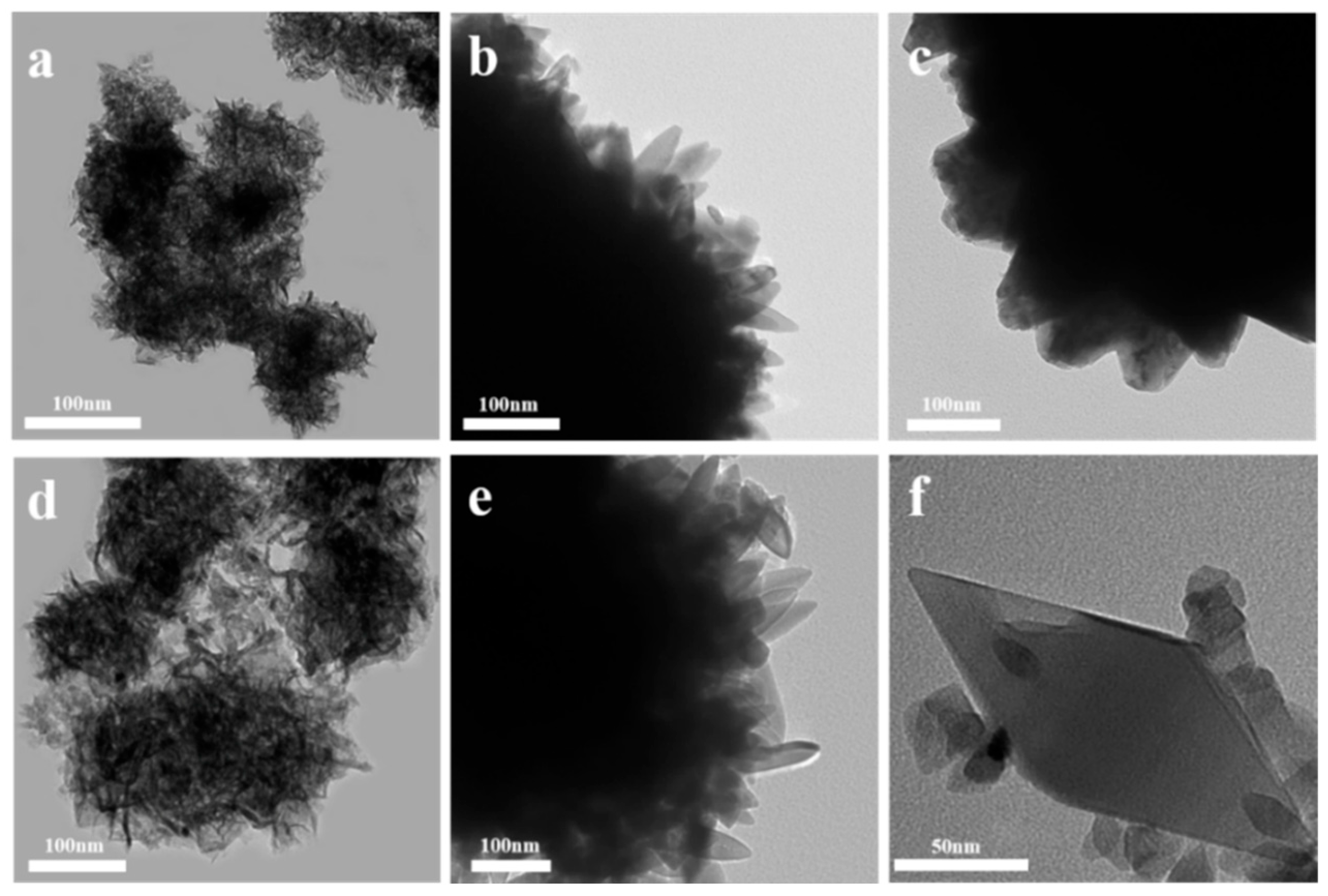
Figure 4 shows the transmission electron microscopy images of three different morphologies of titanium dioxide carriers before loading ruthenium, corresponding to the nanosheet flowers, long prisms, and tetragonal double cones structures. The figure clearly displays the typical morphological features of each carrier: TNSFs present a three-dimensional flower-like structure composed of two-dimensional nanofilms, with clear layers and uniform thickness, showing good hierarchical orderliness; TNEBs have a distinct double cone morphology along the long axis extension, with a significant aspect ratio, smooth surface, and sharp edges, indicating their preferential growth along a specific crystal direction; and TNQBs show a regular tetrahedral symmetric double cone structure, with uniform cone sizes and distinct geometric contours, indicating highly consistent crystal growth habits. All samples have a uniform morphology and complete structure, without obvious agglomeration or structural collapse, providing an ideal base structure for the subsequent uniform loading of ruthenium and the construction of the metal–carrier interface.
Supplementary Figure S1 shows the transmission electron microscopy (TEM) images of the three types of Ru-based catalyst (Ru/TNSFs, Ru/TNEBs, and Ru/TNQBs), which visually demonstrate the deposition state and dispersion of the ruthenium species on different morphological titanium dioxide carriers. From left to right in the figure, the samples correspond to nanosheet flower-like, long prismatic, and tetragonal double-cone structures. The low-magnification images show that after loading Ru, the main morphologies of the three TiO2 carriers remain intact, without structural collapse or significant deformation, indicating that the loading process has good structural compatibility. The high-magnification images clearly display the details of the metal–carrier interface: the carrier surface is covered with small, uniform dark spots, which correspond to highly dispersed ruthenium nanoparticles. The particle diameters are mainly in the range of 2–5 nm, without obvious agglomeration, indicating that Ru has achieved good single-dispersion loading on the carriers with different exposed crystal planes. The interface between Ru particles and TiO2 carriers is clear, and the two are in close contact, providing direct microscopic structural evidence for the formation of interface charge transfer and electronic metal–carrier interactions. The above results indicate that by controlling the morphology, the optimized distribution of Ru active sites on specific crystal planes can be achieved, thereby laying a structural foundation for the differences in catalytic performance.

3.2. Evaluation of Catalytic Performance for the Selective Hydrogenation of Benzene to Cyclohexene and Structure–Activity Analysis

3.2.1. Study of the Benzene-Selective Hydrogenation Performance of Catalysts

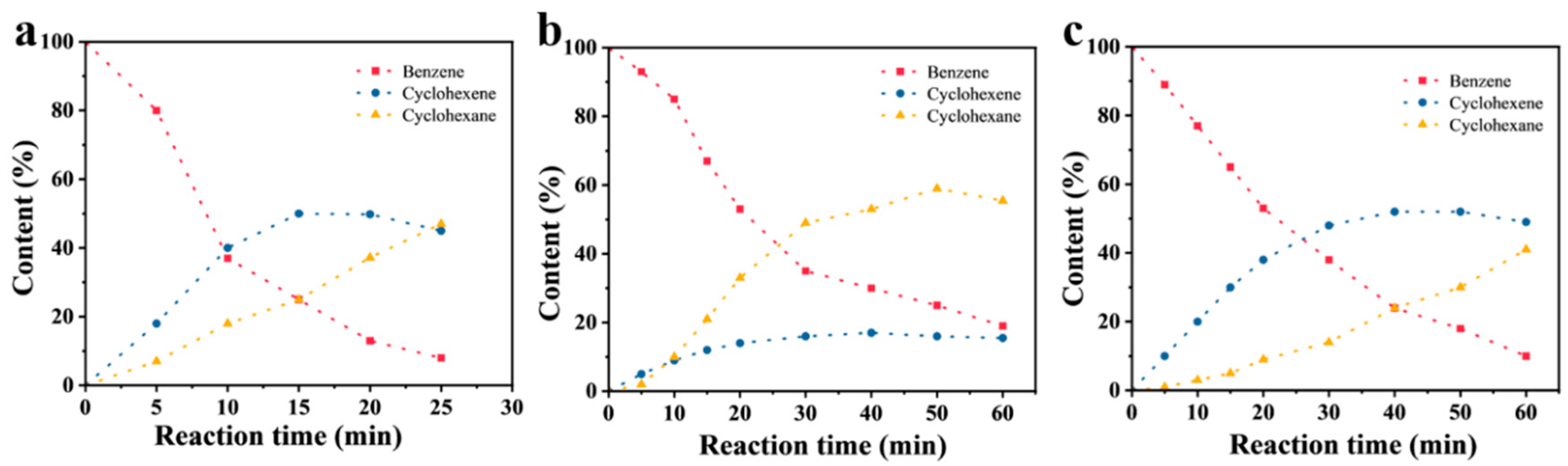
The benzene-selective hydrogenation reactions of the prepared Ru/TNSF, Ru/TNEB, and Ru/TNQB catalysts were tested, with the results being shown in Supplementary Table S1. From these results, it can be seen that cyclohexene and cyclohexane are the only products detected. Figure 5 shows the trends for the content of benzene, cyclohexene, and cyclohexane in the benzene-selective hydrogenation reaction of Ru/TNSF, Ru/TNEB, and Ru/TNQB catalysts with the reaction time. Specifically, the content of benzene decreases throughout the reaction process, the content of cyclohexane increases monotonically, and the content of cyclohexene shows a parabolic change trend. The entire change pattern conforms to the behavior characteristics of the continuous hydrogenation of benzene. From the figure and the table, it can be seen that the performance of the Ru/TNQB catalyst is superior. Under the conditions of a reaction temperature of 140 °C, a hydrogen pressure of 5.0 Mpa, and a rotation speed of 1000 rpm, when the benzene conversion rate is 42.8%, the cyclohexene selectivity remains close to 82.27%, and the maximum cyclohexene yield is 53.22%. The Ru/TNEB catalyst is the opposite, displaying the lowest cyclohexene selectivity. After 20 min of the reaction, the benzene conversion rate reaches 48.34%, and the cyclohexene selectivity is only 30.57%. The Ru/TNSF catalyst has the best reaction activity. After 8 min of the reaction, the benzene conversion rate reaches 43.2%, and the cyclohexene selectivity reaches 73.36%. It is worth noting that although Ru/TNSFs, Ru/TNEBs, and Ru/TNQBs are all catalyst materials with a rutile structure as the main component, the selectivity and yield do not belong to the same order of magnitude. This performance difference is likely due to the completely different crystal plane structures of the three carriers, nanosheet flowers (TNSFs), long prisms (TNEBs), and tetragonal double pyramids (TNQBs), which each expose different crystal planes with different atomic arrangements and surface energies. These differences in crystal plane structures directly affect the surface properties of the materials, such as their hydrophilicity, electron density distribution, and defect states, and thereby regulate the electronic state of the Ru species and the interface interaction with the carrier. Therefore, the differentiated metal–carrier electronic effects induced by different crystal planes ultimately lead to significant differences in the adsorption behavior of benzene, hydrogenation pathways, and the desorption ability of intermediate products, which macroscopically manifest as significant differences in catalytic selectivity and activity.
It should be noted that cyclohexene is a kinetically controlled intermediate, while cyclohexane is the thermodynamically more stable final product. The parabolic variation of cyclohexene concentration with reaction time reflects the competition between its formation and its subsequent hydrogenation. The maximum cyclohexene accumulation occurs when the rates of these two processes become equal, rather than indicating that the hydrogenation of cyclohexene to cyclohexane ceases after cyclohexene is formed. Therefore, the selectivity toward cyclohexene is highly sensitive to reaction conditions, and process scale-up would require careful optimization of parameters such as temperature, H2 pressure, and mass transfer to maintain high selectivity.
Based on the evaluation of catalytic performance, a kinetic analysis was conducted by combining the reaction data. Supplementary Figure S2a shows the natural logarithm of the benzene concentration changing with reaction time, and Supplementary Figure S2b presents the curve of cyclohexene concentration changing with reaction time. Both show a good linear relationship, indicating that the hydrogenation of benzene to cyclohexene conforms to first-order reaction kinetics, while the further hydrogenation of cyclohexene to cyclohexane follows zero-order reaction kinetics [28,29]. Supplementary Figure S2c illustrates the trend of cyclohexene selectivity changing with reaction time, which is consistent with the aforementioned performance evolution pattern: the Ru/TNQB catalyst shows the highest cyclohexene selectivity, followed by the Ru/TNSF catalyst, and the selectivity of the Ru/TNEB catalyst is the lowest. Supplementary Figure S2d presents the relationship between cyclohexene selectivity and benzene conversion rate, and its linear characteristic further confirms the kinetic behavior of selectivity gradually decreasing with the increase in conversion rate. The above kinetic results systematically clarify that different carrier morphologies, by influencing the adsorption of reactants, the stability of intermediates, and the energy barriers of hydrogenation pathways, ultimately cause significant differences in catalytic selectivity and reaction order characteristics on a macroscopic scale [30,31].
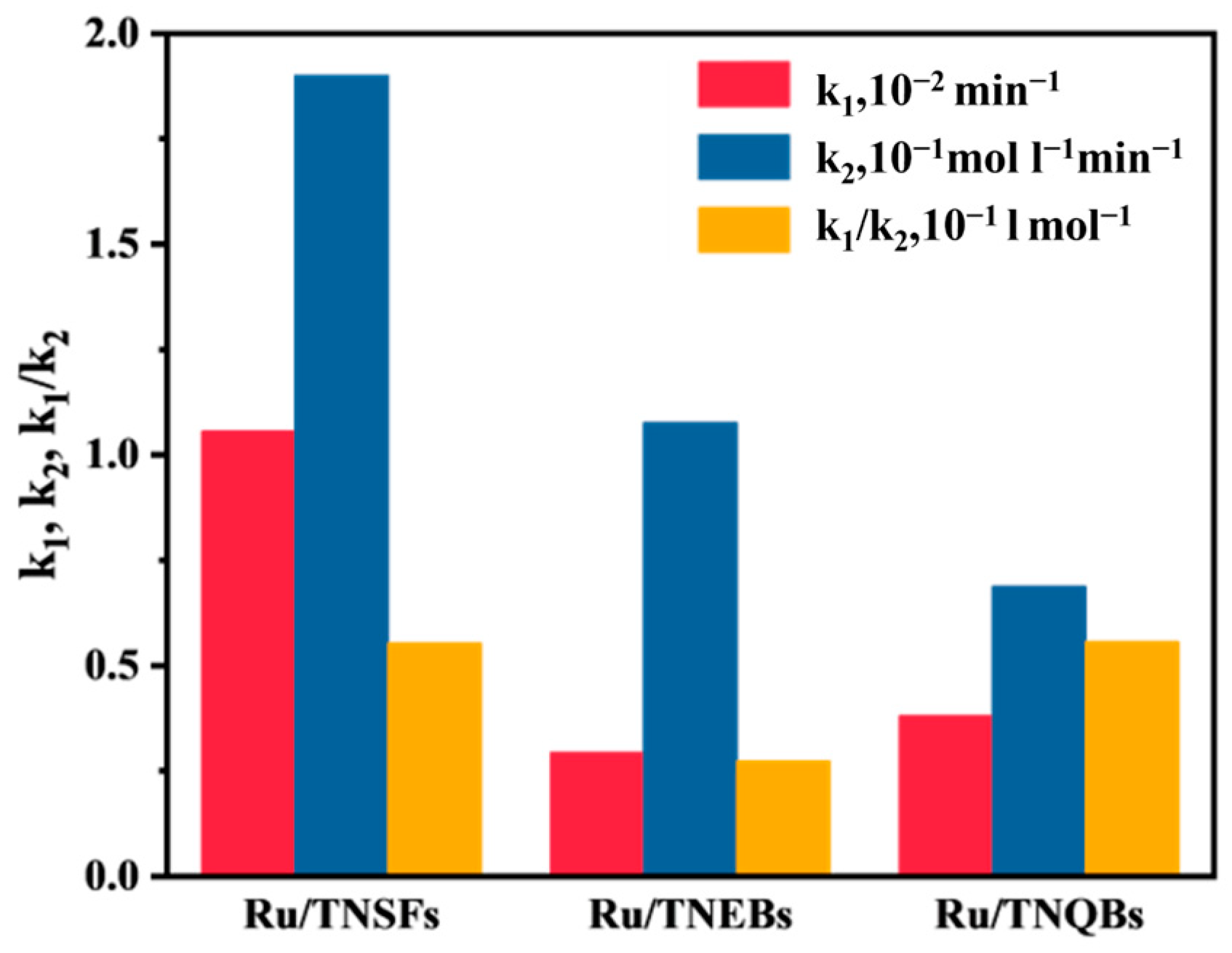
By performing linear fitting on the kinetic curves, the apparent rate constants k1 (benzene → cyclohexene) and k2 (cyclohexene → cyclohexane) for the two-step hydrogenation of benzene were obtained [2]. The research results are shown in Figure 6. The selectivity of cyclohexene is mainly determined by the ratio of the rate constants of the two-step reactions: the higher the ratio, the less prone the intermediate product cyclohexene is to undergoing deep hydrogenation, and thus the higher the selectivity. Among the three catalysts, the Ru/TNQB catalyst has the highest value, followed by the Ru/TNSF catalyst, and the ratio of the Ru/TNEB catalyst is the lowest. This kinetic sequence is completely consistent with the selectivity trend observed in the experiment, thereby explaining from the perspective of reaction kinetics why Ru/TNQBs can achieve the optimal cyclohexene yield. These differences can be further attributed to the different strengths of the electronic metal–support interactions (EMSI) induced by different carrier morphologies. The exposed crystal surface structure of the carrier regulates the electronic density of Ru nanoparticles through the EMSI effect, affecting the activation energy barriers for reactants and intermediates. Stronger EMSI often leads Ru to present different electron-deficient states, facilitating the desorption of cyclohexene and inhibiting its further hydrogenation, thus resulting in a higher ratio and better selectivity. Therefore, the carrier crystal surface structure regulates the electronic state of the metal through EMSI and is a key factor determining the kinetic behavior of benzene’s partial hydrogenation and the final catalytic performance.

3.2.2. Analysis of the Relationship Between Catalyst Structure and Performance

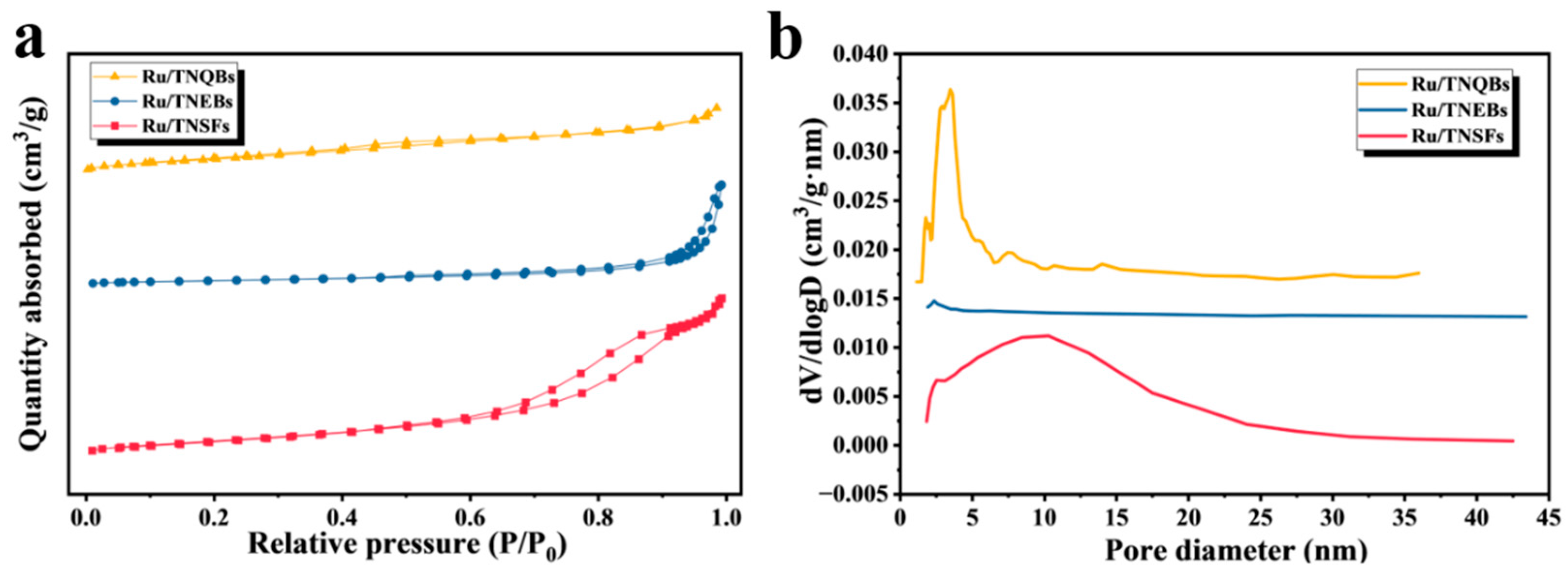
To systematically investigate the influence of the pore structure characteristics of the catalysts on the reaction performance, the specific surface area and pore structure of the three catalysts were characterized by means of the nitrogen adsorption–desorption method. The results are shown in Figure 7 and Supplementary Table S2. The pore structure parameters indicate that there are significant differences in the textural properties of the three catalysts: the Ru/TNEB catalyst has the largest specific surface area (74.015 m2·g−1), while the Ru/TNQB catalyst has the smallest specific surface area (19.795 m2·g−1). However, in terms of pore size distribution, the Ru/TNQB catalyst exhibits the largest average pore diameter (27.168 nm) and pore volume (0.221 cm3·g−1), being significantly greater than those of the Ru/TNSF (3.050 nm, 0.078 cm3·g−1) and Ru/TNEB catalysts (11.845 nm, 0.135 cm3·g−1).
This contrasts with its optimal catalytic performance observed in the benzene-selective hydrogenation reaction, indicating that in this reaction system, larger pore diameters and pore volumes are conducive to the mass transfer and diffusion of reactants and products, thereby potentially alleviating the problem of insufficient accessibility of active sites due to the lower specific surface area. In summary, the structural differences in the carrier not only affect its surface electronic state and its interaction with the metal, but also significantly alter the textural properties of the catalyst, thereby jointly regulating its catalytic behavior [32].
To deeply explore the fundamental reasons for the excellent performance of the Ru/TNQB catalyst and its structure–activity relationship, this study utilized X-ray photoelectron spectroscopy (XPS) to characterize the surface chemical states of the three catalysts. The results are shown in Supplementary Figure S3 [24,33]. During the selective hydrogenation of benzene, residual chloride ions may cause catalyst poisoning, significantly reducing the selectivity of cyclohexene. Supplementary Figure S3a shows the full spectrum, which reveals that, in addition to the characteristic peaks of the main elements such as Ru, Ti, and O, only trace C signals were detected, and no Cl residues were found, indicating that the preparation process effectively avoided the contamination of chlorine species. Supplementary Figure S3b presents the superimposed spectrum of Ru 3p and Ti 2p. The Ti 2p spectra of Ru 3p and Ru 2p of Ru 3p/TNEBs and Ru 3p/TNSEs can be fitted to form characteristic peaks at 458.6 eV (Ti 2p3/2) and 464.9 eV (Ti 2p1/2), which are attributed to Ti4+. However, in Ru/TNQBs, in addition to the Ti4+ signal, obvious Ti3+ characteristic peaks appeared at 458.0 eV and 462.5 eV [34,35], indicating that there are abundant oxygen vacancies and Ti3+ defects on the surface of this catalyst, which form a significant difference from the other two catalysts. It is particularly important to note that the peak area ratios of the two different electron-deficient states of ruthenium (Ru 3p1/2 and Ru 3p3/2) in the three catalysts are significantly different. For the convenience of subsequent discussion, the electronic states corresponding to Ru 3p1/2 and Ru 3p3/2 are marked as Ruα and Ruβ [36].
After peak-fitting of the Ru 3d XPS spectrum in Supplementary Figure S3c, it can be identified that the metal Ru0 (Ru 3d5/2~280.9 eV; Ru 3d3/2~285.3 eV) [34] coexists with the oxidized Ru species (RuOx 3d5/2~282.1 eV and RuOx 3d3/2~286.9 eV), indicating that some Ru nanoparticles are in a metallic state and some are in an oxidized state. Moreover, the binding energies of Ru 3p and Ru 3d have significantly deviated from the standard spectrum, and the peak positions are listed in Supplementary Table S3. This directly confirms the existence of electronic metal–support interaction (EMSI), and its intensity varies due to the different crystal plane structures of the carrier [37]. Supplementary Figure S3d is the O1s spectrum. The peak located at 529.4–530.0 eV belongs to lattice oxygen (O lattice), the peak near 532.2 eV belongs to surface hydroxyl (O hydroxyl), and the peak at approximately 533.0 eV corresponds to adsorbed water (O adsorbed water) [24,35,38,39]. The Ru/TNQB catalyst has significantly higher signal intensities of these three types of oxygen species than other samples. Combined with its abundant Ti3+ defects, this indicates that the surface of this catalyst has stronger hydrophilicity and more surface active oxygen species. This surface property helps to optimize the adsorption and desorption balance of the reaction intermediate cyclohexene, thereby improving the selectivity of cyclohexene [40,41,42]. In summary, the XPS results reveal, from the perspective of surface chemical state and electronic structure, that different carrier morphologies adjust the electronic density of Ru (Ruβ/(Ruα + Ruβ) ratio) and the proportion of carrier defects (Ti3+) through differentiated EMSI effects and affect the surface oxygen species and hydrophilicity. These factors jointly determine the final performance of the catalyst in the benzene-selective hydrogenation reaction.
Based on the fitting results of XPS data (Supplementary Table S4), the relative proportions of Ruβ among the three catalysts (Ruβ/(Ruα + Ruβ)) show significant differences, with the order being as follows: Ru/TNQBs (82.22%) > Ru/TNSFs (68.85%) > Ru/TNEBs (46.13%). This order is exactly consistent with their catalytic performances in the selective hydrogenation of benzene, indicating a significant positive correlation between the relative abundance of Ruβ species and the selectivity of cyclohexene. Combined with the previous analysis, Ruβ corresponds to a stronger electron-deficient Ru species, and its higher proportion reflects a stronger electronic metal–support interaction (EMSI) between the carrier and the metal. This strong EMSI effect causes a reduction in the electronic density on the surface of Ru nanoparticles, facilitating the timely desorption of cyclohexene and inhibiting its further hydrogenation, thereby enhancing the selectivity of intermediate products. Therefore, the highest Ruβ proportion in Ru/TNQBs is in correspondence with its optimal catalytic performance, confirming that regulating the Ru electronic state through the crystal plane structure of the carrier is an effective strategy for achieving high selectivity hydrogenation.
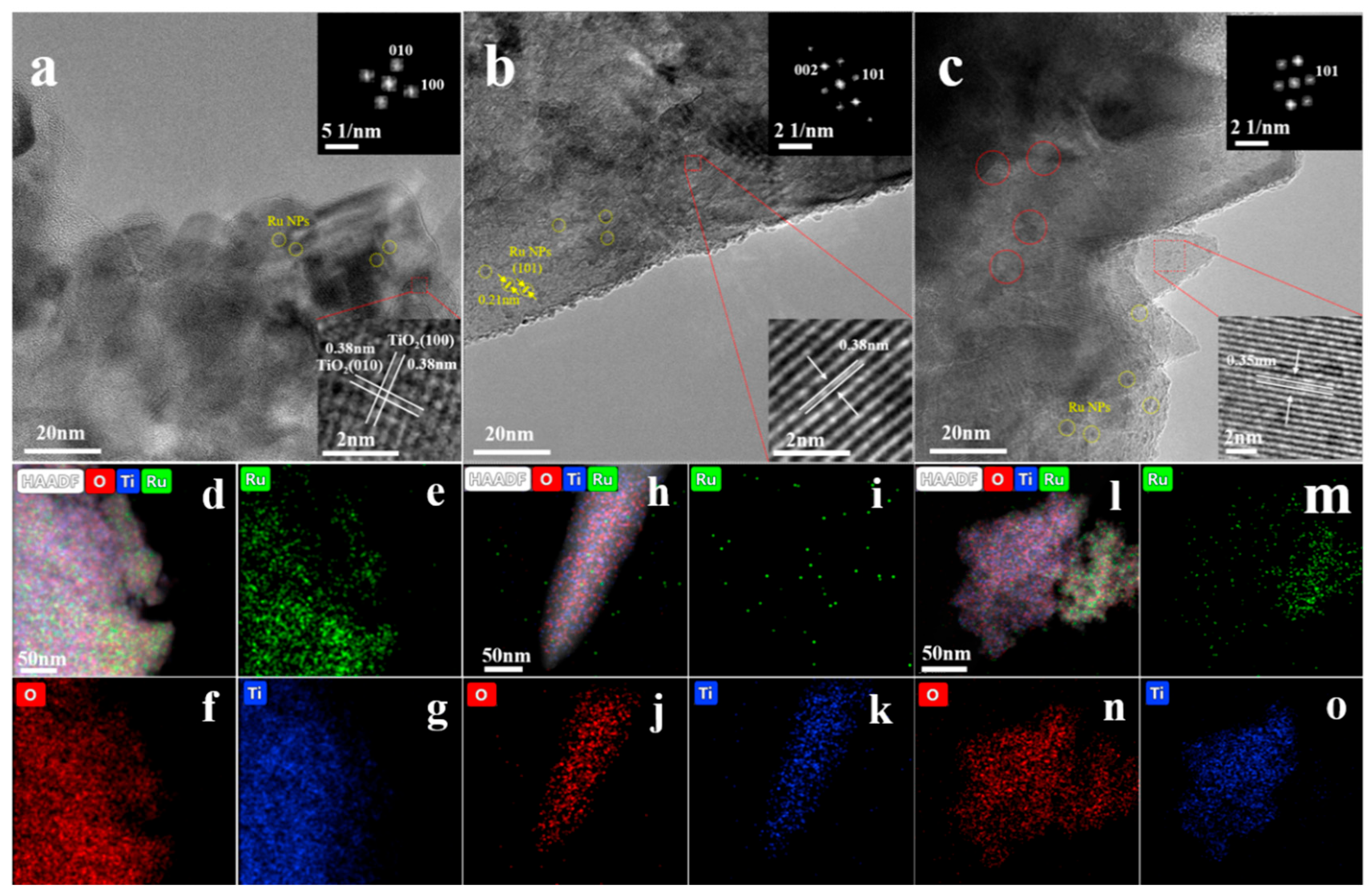
Figure 8 shows the high-resolution transmission electron microscopy (HRTEM) images and energy distribution maps of the Ru/TNSF, Ru/TNEBs and Ru/TNQB catalysts. In Figure 8a, there are vertical lattices parallel to the TiO2 (010) and (100) crystal planes, with a stripe spacing of 0.38 nm. The corresponding Fourier transform (FFT) mode (the inset in Figure 8a) can point the diffraction spots in the [001] direction. Therefore, it can be concluded that the Ru/TNSFs material is mainly composed of (001). At the same time, only one crystal lattice stripe is observed in the entire figure, indicating its single-crystal characteristic. Based on geometric estimation, the proportion of the (001) crystal plane is approximately 82%. The inset in Figure 8b has a lattice spacing of approximately 0.38 nm, corresponding to the (010) crystal plane of anatase, and the corresponding Fourier transform (FFT) pattern (the inset in Figure 8b) shows the diffraction spots along the [010] axis band. According to geometric estimation, the percentage of the (010) crystal plane in the Ru/TNEBs material is approximately 70%. Figure 8c displays a lattice stripe with a spacing of 0.35 nm, belonging to the (101) crystal plane of anatase. Based on the symmetry of the tetragonal double cone-type TiO2, the main crystal plane of Ru/TNQBs is the (101) crystal plane, and based on geometric estimation, the percentage of the (101) crystal plane is estimated to be 94%. Combining the atomic arrangement symmetry and projection characteristics shown by the spatial lattice model corresponding to each region, the above crystal plane orientation determination is further confirmed from the geometric structure, thereby verifying that the controlled exposure of specific active crystal planes can be achieved through morphology regulation [24,33].
In Figure 8a–c, the areas marked by the yellow circles show distinct lattice patterns from the surrounding TiO2 substrate. Analyzing the lattice spacings of these areas, it was found that the value of 0.21 nm matches the (101) crystal plane of the metal Ru. This directly confirms that the Ru nanoparticles have been successfully loaded and are in a highly dispersed state on the carrier surface. The area marked by the red circle in Figure 8c shows obvious crystal defect characteristics. This observational result is highly consistent with the Ti3+ signal detected in the previous XPS analysis, jointly indicating that rich reducible defect sites are formed on the carrier surface dominated by specific crystal planes (especially the (101) plane), providing a crucial structural basis for the formation of the electronic metal–support interaction (EMSI).
To verify the consistency of the elemental distribution and chemical state among the three catalysts, a systematic energy spectrum (EDS) surface scanning analysis was conducted on them. The results are shown in Figure 8d–o. In all samples, the Ti and O elements exhibited a highly uniform and continuous distribution, and their spatial profiles perfectly matched the morphology of the carrier. This confirmed the integrity and chemical homogeneity of the TiO2 carrier structure. At the same time, the Ru element also showed a uniformly dispersed distribution pattern on the three catalysts, and no obvious element agglomeration was observed, indicating that the Ru species were uniformly loaded on the surfaces of the carriers with different crystal face structures.
Based on a detailed analysis of the morphology and structure of the catalysts, in order to further explore the potential influence of surface hydrophilicity on the selectivity of cyclohexene, the surface wetting properties of the three catalysts were characterized using static water contact angle measurement. The results are shown in Supplementary Figure S4. Ru/TNEBs, Ru/TNSFs, and Ru/TNQBs all exhibited hydrophilic characteristics, but the degree of hydrophilicity varied significantly. Among them, Ru/TNEBs had the largest contact angle (61.2°), with relatively weaker hydrophilicity; Ru/TNSFs were second (46.3°); and Ru/TNQBs had the smallest contact angle (41.5°), with the strongest hydrophilicity. This trend is consistent with the XPS analysis results: the surface of Ru/TNQBs has more abundant Ti3+ defects and a higher proportion of hydroxyl oxygen and adsorbed water species, which together enhance their surface hydrophilicity. Stronger hydrophilicity is conducive to promoting the contact between the aqueous reaction medium and the active sites, improving the adsorption and mass transfer efficiency of benzene molecules on the catalyst surface, and thus accelerating the hydrogenation reaction process; at the same time, it also helps the timely desorption of the intermediate product cyclohexene, inhibiting its further deep hydrogenation to cyclohexane. Therefore, the optimization of surface hydrophilicity is one of the important factors for Ru/TNQBs to achieve higher cyclohexene selectivity, and it improves the explanation of the structure–activity relationship from the perspective of interface properties.

3.2.3. The Influence of Ru Loading Amount on the Catalytic Performance of Ru/TNQBs

To optimize the performance of the Ru/TNQB catalyst, the influence of ruthenium loading on the selectivity of benzene hydrogenation was investigated. In this study, catalysts with loading percentages of 5 wt%, 10 wt%, and 15 wt% were prepared, and their performance was tested under the same conditions. The results are shown in Supplementary Figure S5 and Table S5. When the loading percentage increased from 10 wt% to 15 wt%, the benzene conversion rate remained at 42.5%, but the selectivity of cyclohexene decreased to 73.6%, and the maximum yield was only 31.3%. This might be due to the higher loading percentage causing Ru nanoparticles to aggregate, increasing the spatial density of active sites, and accelerating the deep hydrogenation of cyclohexene to cyclohexane. When the loading percentage was reduced to 5 wt%, the dispersion of Ru improved, but the number of active sites per unit catalyst was insufficient, resulting in a decrease in reaction activity, and both the selectivity (70.3%) and yield (28.9%) were low. This indicates that when the loading percentage is too low, it is difficult to maintain an effective hydrogenation and desorption balance.
In contrast, the catalyst with 10 wt% loading reached a benzene conversion rate of 42.8% within 20 min, with a selectivity of 82.27% for cyclohexene and a maximum yield of 53.22%, demonstrating the best overall catalytic performance. This result shows that at this loading percentage, the catalyst achieved the optimal balance among the number of active sites, metal dispersion, and particle size, providing sufficient hydrogenation activity while facilitating the timely desorption of the intermediate product cyclohexene, thereby inhibiting its further conversion. Therefore, by precisely controlling ruthenium loading, the activity and selectivity of the catalyst can be effectively coordinated, providing an important basis for the design of high-performance benzene-selective hydrogenation catalysts.

3.2.4. The Influence of Reaction Conditions on the Catalytic Performance of Ru/TNQBs

In order to determine the optimal process conditions of the Ru/TNQB catalyst in the selective hydrogenation of benzene, the effects of catalyst dosage, reaction temperature, hydrogen pressure, and stirring speed on its catalytic performance were systematically investigated. The results are shown in Supplementary Figure S6. The dosage of the catalyst has a significant impact on the reaction performance (Supplementary Figure S6a). As the dosage increases, the conversion rate of benzene continues to rise. However, if the dosage is too high, there will be too many active sites, causing the intermediate product cyclohexene to undergo further deep hydrogenation, resulting in a decrease in selectivity. Therefore, 0.5 g was selected as the appropriate dosage.
The influence of reaction temperature is shown in Supplementary Figure S6b. An increase in temperature is beneficial for enhancing reaction activity: at 130 °C, the conversion rate is 40.1% and the selectivity is 80.0%; when the temperature rises to 140 °C, the conversion rate significantly increases while the selectivity remains basically unchanged; when the temperature reaches 150 °C, the conversion rate continues to rise but the selectivity significantly decreases. This might be because the reaction rate accelerates at high temperatures, leading to excessive hydrogenation of cyclohexene. Choosing 140 °C as the reaction temperature can provide a better balance between activity and selectivity.
The optimization results of hydrogen pressure are shown in Supplementary Figure S6c. When the pressure varies within the range of 4–6 MPa, the selectivity of cyclohexene shows a volcano-shaped curve, reaching the highest value at 5 MPa. Therefore, 5 MPa is determined as the optimal hydrogen pressure. The influence of stirring speed is shown in Supplementary Figure S6d. As the speed increases, the selectivity first rises and then drops. An excessively high speed may cause the catalyst particles to adhere to the reactor wall due to centrifugal force, reducing the effective contact area and thus having an adverse effect on the reaction. Therefore, 1000 rpm is selected as the suitable speed.
Based on the above results, the optimal reaction conditions for the Ru/TNQB catalyst were determined as follows: catalyst dosage of 0.5 g, temperature of 140 °C, hydrogen pressure of 5 MPa, and stirring speed of 1000 rpm. Under these conditions, the reaction was carried out for 20 min, with a benzene conversion rate of 42.8%, a cyclohexene selectivity of 82.27%, and the corresponding maximum cyclohexene yield of 53.22%.

3.2.5. The Catalytic Stability of Ru/TNQBs

The cyclic stability of the catalyst is an important criterion for evaluating its industrial feasibility. Therefore, in this study, under the optimal conditions determined, the Ru/TNQB catalyst with the best performance was subjected to cyclic stability tests. After each round of reaction, the catalyst was only subjected to filtration and drying treatment, without any activation process, and was directly put into the next round of the reaction. The results are shown in Supplementary Figure S7. After six consecutive cycles of use, the catalyst maintained a benzene conversion rate of around 40% and a cyclohexene selectivity of approximately 80%, demonstrating good stability in use.
The excellent cyclic stability of the Ru/TNQB catalyst is attributed to the unique structural stability of the tetragonal double-conical support. This support has a regular morphology and complete crystallization, providing a stable anchoring site for Ru nanoparticles, which can effectively inhibit the migration, agglomeration, or detachment of metal particles during the reaction process. At the same time, the stable crystal planes exposed by the support and the strong electronic interaction between the support and the metal help to keep the electronic state of the Ru active center basically unchanged during the cycle, such as by maintaining a high Ruβ ratio. Therefore, the Ru/TNQB catalyst can still maintain its catalytic performance after multiple uses and has good potential for practical applications.

4. Conclusions

The crystal plane structure of the carrier is the key factor in regulating the electronic states of EMSI and Ru. Three TiO2 carriers (TNSFs, TNEBs, and TNQBs) with mostly exposed (001), (010), and (101) crystal planes were successfully prepared. HRTEM and XPS analyses confirmed that different crystal planes induced differential EMSI effects. Among them, the tetragonal double cone (TNQBs) carrier exposed the (101) crystal plane, which induced the strongest EMSI, resulting in abundant Ti3+ defects on its surface and a high proportion of electron-deficient Ru species (Ruβ reaching 82.22%).
The electronic state of Ru, represented by the proportion of Ruβ species, plays a decisive role in determining the catalytic performance. The relative abundance order of Ruβ species is Ru/TNQBs > Ru/TNSFs > Ru/TNEBs, which is exactly the same as the order of cyclohexene selectivity in the benzene-selective hydrogenation reaction of the three catalysts. The strong EMSI effect endows Ru with electron-deficient characteristics, optimizing the reaction pathway; on the one hand, it ensures sufficient hydrogenation activity (higher k1), and on the other hand, it significantly weakens the further adsorption and hydrogenation of the intermediate product cyclohexene (suppressing k2), thereby achieving the highest k1/k2 ratio and selectivity.
The hierarchical structural characteristics synergistically enhanced the catalytic performance. In addition to the electronic effect, the optimal catalyst, the Ru/TNQB catalyst, has the largest pore size and pore volume, which is conducive to mass transfer; its surface exhibits the strongest hydrophilicity due to abundant Ti3+ defects and oxygen-containing species, promoting the contact between the reaction medium and the active sites and the desorption of cyclohexene. The synergistic effect of the above textural and interface properties brings about excellent comprehensive catalytic performance, with a benzene conversion rate of 42.8%, a cyclohexene selectivity of 82.27%, and a yield of 53.22%.
The catalyst also demonstrated excellent stability and promising potential for practical applications. Under optimized reaction conditions, the Ru/TNQB catalyst maintains high activity and selectivity after six consecutive cycles of use, demonstrating good stability and application potential. This is mainly because the tetragonal double cone carrier structure is regular and stable, providing firm anchoring sites for Ru nanoparticles, and the strong electronic metal–support interaction also helps to stabilize the electronic state of Ru.

Supplementary Materials

The following supporting information can be downloaded at: https://www.mdpi.com/article/10.3390/app16157453/s1. Figure S1: TEM images of Ru/TNSFs (a,d), Ru/TNEBs (b,e), and Ru/TNQBs (c,f); Figure S2: Kinetic schematic diagram of Ru/TNSFs, Ru/TNEBs, and Ru/TNQBs catalysts; Figure S3: XPS spectra of Survey (a), Ru 3p + Ti 2p (b), Ru 3d + C 1s (c), and O 1s orbitals (d) of Ru/TNSFs, Ru/TNEBs, and Ru/TNQBs catalysts; Figure S4: Static water contact angle diagrams of Ru/TNSFs, Ru/TNEBs, and Ru/TNQBs catalysts; Figure S5: Schematic diagram of the hydrogenation process of benzene by Ru/TNQBs catalysts with Ru loading amounts of 5% (a), 10% (b), and 15% (c); Figure S6: The influence of Catalyst weight (a), Reaction temperature (b), Reaction pressure (c), and Reaction speed (d) on the catalytic performance of Ru/TNQBs; Figure S7: Catalytic stability of the Ru/TNQBs catalyst; Table S1: Hydrogenation parameters of benzene for Ru/TNSFs, Ru/TNEBs, and Ru/TNQBs catalysts a; Table S2: BET parameters of Ru/TNSFs, Ru/TNEBs, and Ru/TNQBs catalysts; Table S3: XPS peak positions of Ru/TNSFs, Ru/TNEBs, and Ru/TNQBs catalysts; Table S4: Parameters of Ruα and Ruβ for Ru/TNSFs, Ru/TNEBs, and Ru/TNQBs catalysts; Table S5: Parameters of benzene hydrogenation by Ru/TNQBs catalysts with different Ru loading amounts a.

Author Contributions

Conceptualization, Q.Z. and L.H.; methodology, Q.Z., L.H. and B.Z.; software, B.Z.; validation, Q.Z. and X.C.; formal analysis, B.Z.; investigation, Y.W.; resources, Y.W.; data curation, Q.Z. and X.C.; writing—original draft preparation, Q.Z. and X.C.; writing—review and editing, Y.W., L.H. and B.Z.; visualization, L.H. and B.Z.; supervision, B.Z.; project administration, Y.W. All authors have read and agreed to the published version of the manuscript.

Funding

This research received no external funding.

Institutional Review Board Statement

Not applicable.

Informed Consent Statement

Not applicable.

Data Availability Statement

The original contributions presented in this study are included in the article/Supplementary Material. Further inquiries can be directed to the corresponding author.

Conflicts of Interest

The authors Qian Zhang and Yatao Wang were employed by Coal Chemical R&D Center of Kailuan Group. The remaining authors declare that the research was conducted in the absence of any commercial or financial relationships that could be construed as a potential conflict of interest.

References

  1. Pu, J.C.; Dari, M.D.; Tang, X.Q.; Yuan, P.Q. Diffusion of benzene through water film confined in silica mesopores: Effect of competitive adsorption of solvent. Chem. Eng. Sci. 2020, 224, 115793. [Google Scholar] [CrossRef]
  2. Li, A.; Shen, K.; Chen, J.; Li, Z.; Li, Y. Highly selective hydrogenation of phenol to cyclohexanol over MOF-derived non-noble Co-Ni@NC catalysts. Chem. Eng. Sci. 2017, 166, 66–76. [Google Scholar] [CrossRef]
  3. Zhao, Y.; Zhou, J.; Zhang, J.; Wang, S. Liquid-phase selective hydrogenation of benzene to cyclohexene on Ru/Al2O3–ZrO2/cordierite monolithic catalysts. J. Mol. Catal. A Chem. 2009, 309, 35–39. [Google Scholar] [CrossRef]
  4. Sun, H.; Pan, Y.; Li, S.; Zhang, Y.; Dong, Y.; Liu, S.; Liu, Z. Selective hydrogenation of benzene to cyclohexene over Ce-promoted Ru catalysts. J. Energy Chem. 2013, 34, 684–694. [Google Scholar] [CrossRef]
  5. Melgo, M.S.; Lindner, A.; Schuchardt, U. Wacker oxidation of cyclohexene in the presence of Pd(NO3)2/CuSO4/H3PMo12O40. Appl. Catal. A Gen. 2004, 273, 217–221. [Google Scholar] [CrossRef]
  6. Spod, H.; Lucas, M.; Claus, P.D.P. Selective Hydrogenation of Benzene to Cyclohexene over 2Ru/La2O3-ZnO Catalyst without Additional Modifiers. ChemCatChem 2016, 8, 2659–2666. [Google Scholar] [CrossRef]
  7. Yan, X.; Zhang, Q.; Zhu, M.; Wang, Z. Selective hydrogenation of benzene to cyclohexene over Ru–Zn/ZrO2 catalysts prepared by a two-step impregnation method. J. Mol. Catal. A Chem. 2016, 413, 85–93. [Google Scholar] [CrossRef]
  8. Wang, Z.; Song, M.; Li, X.; Chen, J.; Liang, T.; Chen, X.; Yan, Y. Copolymerization-Regulated Hydrogen Bonds: A New Routine for High-Strength Copolyamide 6/66 Fibers. Polymers 2022, 14, 3517. [Google Scholar] [CrossRef] [PubMed]
  9. Yang, M.; Wang, Y.; Liu, W.; Lu, J.; Shi, M.; Wu, S.; Bu, L.; Zhi, Y.; Wang, Z.; Sang, J.; et al. Synthesis of Hierarchical ZSM-11 Nanorods Aggregates and Catalytic Properties in Cyclohexene Hydration to Cyclohexanol. ChemistrySelect 2023, 8, e202203642. [Google Scholar] [CrossRef]
  10. Wei, S.; Li, M.; Li, K.; Zhong, S.; Su, Y.; Zhang, R.; Liu, R. Highly enhanced direct catalytic oxidation of cyclohexane to adipic acid by prussian blue analogues-derived C, N doped CuCo composite catalysts. Chem. Eng. Sci. 2024, 295, 120131. [Google Scholar] [CrossRef]
  11. Niklas, P.; Yue, L.; Florian, Z.; Shi, H.; Gary, L.H.; Johannes, A.L. Impact of the Local Concentration of Hydronium Ions at Tungstate Surfaces for Acid-Catalyzed Alcohol Dehydration. J. Am. Chem. Soc. 2021, 143, 20133–20143. [Google Scholar] [CrossRef] [PubMed]
  12. Guo, L.; Yao, J.; Bao, X.; Zhu, H. Efficient cyclohexane dehydrogenation over Pt/B–ZrO2 for H2 production. Green Energy Environ. 2026, 11, 105–118. [Google Scholar] [CrossRef]
  13. Wang, J.; Liu, B.; Liu, X.; Chong, M.; Cheng, D.; Chen, F. Regulation of metal-support interaction by pentacoordinate Al3+ content on CeO2/γ-Al2O3 catalyst for oxidative dehydrogenation of cyclohexane. Chin. J. Chem. Eng. 2025, 86, 70–77. [Google Scholar] [CrossRef]
  14. Liu, J.L.; Zhu, Y.; Liu, J.; Pei, Y.; Li, Z.; Li, H.; Li, H.; Qiao, M.; Fan, K. Discrimination of the roles of CdSO4 and ZnSO4 in liquid phase hydrogenation of benzene to cyclohexene. J. Catal. 2009, 268, 100–105. [Google Scholar] [CrossRef]
  15. Qiao, Y.; Guo, Y.; Zhao, Y.; Chang, C.; Wang, S.; Zhang, X.; Gao, F.; Chen, R.; Hou, L. MOF-derived three-dimensional porous dodecahedral structured bimetallic Mn/Co-C-N composite for high-performance durable oxygen reduction reaction electrocatalysts. Nanotechnology 2025, 36, 035703. [Google Scholar]
  16. Zhang, D.; Fan, S.; Fan, B.; Jia, X.; Wang, Y.; Chen, L.; Liu, W.; Xie, Z. Efficient Recovery of Ruthenium from Spent Zirconia-Supported Ruthenium Catalysts by Sodium Bisulfate Roasting Method. J. Sustain. Metall. 2025, 12, 184–195. [Google Scholar] [CrossRef]
  17. Cagnola, E.A.; Quiroga, M.E.; Liprandi, D.A.; L’Argentiere, P.C. Immobilized Rh, Ru, Pd and Ni complexes as catalysts in the hydrogenation of cyclohexene. Appl. Catal. A Gen. 2004, 274, 205–212. [Google Scholar] [CrossRef]
  18. Lu, S.; Lonergan, W.W.; Bosco, J.P.; Wang, S.; Zhu, Y.; Xie, Y.; Chen, J. Low temperature hydrogenation of benzene and cyclohexene: A comparative study between γ -Al2O3 supported PtCo and PtNi bimetallic catalysts. J. Catal. 2008, 259, 260–268. [Google Scholar] [CrossRef]
  19. Liu, S.; Liu, Z.; Zhao, S.; Wu, Y.; Wang, Z.; Yuan, P. Study on the Nanosized Amorphous Ru-Fe-B/ZrO2 Alloy Catalyst for Benzene Selective Hydrogenation to Cyclohexene. J. Nat. Gas Chem. 2006, 35, 81–88. [Google Scholar]
  20. Wang, Z.; Zhang, Q.; Lu, X.; Chen, S.; Liu, C. Ru-Zn catalysts for selective hydrogenation of benzene using coprecipitation in low alkalinity. Chin. J. Catal. 2015, 36, 400–407. [Google Scholar] [CrossRef]
  21. Sun, H.; Fan, Y.; Sun, X.; Chen, Z.; Li, H.; Peng, Z.; Liu, Z. Effect of ZnSO4, MnSO4 and FeSO4 on the Partial Hydrogenation of Benzene over Nano Ru-Based Catalysts. Int. J. Mol. Sci. 2021, 22, 7756. [Google Scholar] [CrossRef] [PubMed]
  22. Chen, Z.H.; Sun, H.J.; Peng, Z.K.; Gao, J.; Li, B.; Liu, Z.; Liu, S. Selective Hydrogenation of Benzene: Progress of Understanding for the Ru-Based Catalytic System Design. Ind. Eng. Chem. Res. 2019, 58, 13794–13803. [Google Scholar] [CrossRef]
  23. Liu, S.; Liu, Z.; Wang, Z.; Zhao, S.; Wu, Y. A novel amorphous alloy Ru-La-B/ZrO2 catalyst with high activity and selectivity for benzene selective hydrogenation. Appl. Catal. A Gen. 2006, 313, 49–57. [Google Scholar] [CrossRef]
  24. Shi, R.; Wang, X.; Zhou, G. Electronic metal—Support interaction directed electron-deficient nanoparticulate Ru on Ti3C2 MXene-derived TiO2 nanoflowers for robust benzene semi-hydrogenation. Appl. Surf. Sci. 2023, 624, 157159. [Google Scholar] [CrossRef]
  25. Jiang, L.; Zhou, G. Promoting the performances of Ru on hierarchical TiO2 nanospheres exposed {0 0 1} facets in benzene semi-hydrogenation by manipulating the metal-support interfaces. J. Catal. 2020, 382, 97–108. [Google Scholar] [CrossRef]
  26. Liang, Y.; Yang, Y.; Zhou, H.; Zou, C.; Xu, K.; Luo, X.; Yu, T.; Zhang, W.; Liu, Y.; Yuan, C. A systematic study on the crystal facets-dependent gas sensing properties of anatase TiO2 with designed {010}, {101} and {001} facets. Ceram. Int. 2019, 45, 6282–6290. [Google Scholar] [CrossRef]
  27. Zhu, F.; Wen, J.; Guo, H.; An, J.; Wang, G.; Ren, G.; Ma, X. Low-temperature catalytic performance improvement of Ru/TiO2{001} for o-dichlorobenzene oxidation. Chem. Eng. J. 2023, 473, 10. [Google Scholar] [CrossRef]
  28. Hao, F.; Zheng, J.; Ouyang, D.; Xiong, W.; Liu, P.; Luo, H. Selective hydrogenation of benzene over Ru supported on surface modified TiO2. Korean J. Chem. Eng. 2021, 38, 736–746. [Google Scholar] [CrossRef]
  29. Liu, S.C.; Guo, Y.Q.; Yang, X.L.; Ji, Y.; Luo, G. Kinetic Equations for Liquid-Phase Selective Hydrogenation of Benzene to Cyclohexene. Chin. J. Catal. 2003, 24, 42–46. [Google Scholar]
  30. Zhou, G.; Dong, Y.; He, D. Bimetallic RuM/TiO2 (M = Fe, Ni, Cu, Co) nanocomposite catalysts facribated by galvanic replacement: Structural elucidation and catalytic behavior in benzene selective hydrogenation. Appl. Surf. Sci. 2018, 456, 1004–1013. [Google Scholar] [CrossRef]
  31. Fan, C.; Zhu, Y.A.; Zhou, X.G.; Liu, Z. Catalytic hydrogenation of benzene to cyclohexene on Ru(0 0 1) from density functional theory investigations. Catal. Today 2011, 160, 234–241. [Google Scholar] [CrossRef]
  32. Lin, W.; Chen, Y.; Zhang, Y.; Wang, J.; Wang, L.; Xu, C.; Nie, R. Surface Synergetic Effects of Ni-ReOx for Promoting the Mild Hydrogenation of Furfural to Tetrahydrofurfuryl Alcohol. ACS Catal. 2023, 13, 11256–11267. [Google Scholar] [CrossRef]
  33. Zhou, G.; Wang, F.; Shi, R. Nanoparticulate Ru on morphology-manipulated and Ti3+ defect-riched TiO2 nanosheets for benzene semi-hydrogenation. J. Catal. 2021, 398, 148–160. [Google Scholar] [CrossRef]
  34. Wu, P.; Lyu, S.; Tian, Y.; Zhao, D.; Ye, J.; She, M.; Song, S.; Ding, T.; Li, X. Identification of active sites for preferential oxidation of CO over Ru/TiO2 catalysts via tuning metal–support interaction. Chem. Eng. J. 2023, 475, 11. [Google Scholar] [CrossRef]
  35. Chen, L.; Wang, S.; Zhang, P.; Chen, Z.; Lin, X.; Yang, H.; Sheng, T.; Lin, W.; Tian, N.; Sun, S.; et al. Ru nanoparticles supported on partially reduced TiO2 as highly efficient catalyst for hydrogen evolution. Nano Energy 2021, 88, 106211. [Google Scholar] [CrossRef]
  36. An, Z.; Ma, N.; Xu, Y.; Yang, H.; Zhao, H.; Wu, L.; Tan, L.; Zou, C.; Meng, F.; Zhang, B.; et al. Shape dependency of CO2 hydrogenation on ceria supported singly dispersed Ru catalysts. J. Catal. 2024, 429, 115245. [Google Scholar]
  37. Zhou, G.B.; Dou, R.F.; Bi, H.Z.; Xie, S.; Pei, Y.; Fan, K.; Qiao, M.; Sun, B.; Zong, B. Ru nanoparticles on rutile/anatase junction of P25 TiO2: Controlled deposition and synergy in partial hydrogenation of benzene to cyclohexene. J. Catal. 2015, 332, 119–126. [Google Scholar] [CrossRef]
  38. Zhong, Z.; Li, J.; Jian, M.; Shu, R.; Tian, Z.; Wang, C.; Chen, Y.; Shi, N.; Wu, Y. Hydrodeoxygenation of lignin-derived phenolic compounds over Ru/TiO2 catalyst: Effect of TiO2 morphology. Fuel 2023, 333, 126241. [Google Scholar] [CrossRef]
  39. Tang, M.; Tong, Q.; Li, Y.; Jiang, R.; Shi, L.; Shen, F.; Wei, Y.; Liu, Z.; Liu, S.; Zhang, J.; et al. Effective and selective electrocatalytic nitrate reduction to ammonia on urchin-like and defect-enriched titanium oxide microparticles. Chin. Chem. Lett. 2023, 34, 269–274. [Google Scholar] [CrossRef]
  40. Lan, K.; Wang, R.; Wei, Q.; Wang, Y.; Hong, A.; Feng, P.; Zhao, D. Stable Ti3+ Defects in Oriented Mesoporous Titania Frameworks for Efficient Photocatalysis. Angew. Chem. Int. Ed. 2020, 59, 17676–17683. [Google Scholar] [CrossRef]
  41. Wu, T.W.; Zhao, H.T.; Zhu, X.J.; Xing, Z.; Liu, Q.; Liu, T.; Gao, S.; Lu, S.; Chen, G.; Asiri, A.; et al. Identifying the Origin of Ti3+ Activity toward Enhanced Electrocatalytic N2 Reduction over TiO2 Nanoparticles Modulated by Mixed-Valent Copper. Adv. Mater. 2020, 32, 2000299. [Google Scholar] [CrossRef]
  42. Hu, J.; Zhang, S.; Cao, Y.; Wang, H.; Yu, H.; Peng, F. Novel Highly Active Anatase/Rutile TiO2 Photocatalyst with Hydrogenated Heterophase Interface Structures for Photoelectrochemical Water Splitting into Hydrogen. ACS Sustain. Chem. Eng. 2018, 6, 10823–10832. [Google Scholar] [CrossRef]
Figure 1. Schematic diagram of the formation mechanisms of Ru/TNSF, Ru/TNEB, and Ru/TNQB catalysts.
Applsci 16 07453 g001
Figure 2. XRD spectra of TNSFs, TNEBs, and TNQBs (a), and Ru/TNSFs, Ru/TNEBs, and Ru/TNQBs (b); XRD magnified spectra of Ru/TNSF, and Ru/TNEB, and Ru/TNQB catalyst materials (c).
Applsci 16 07453 g002
Figure 3. SEM images of Ru/TNSF (a,b), Ru/TNEB (c,d), and Ru/TNQB (e,f) catalysts; EDS spectra of Ru/TNSF (gj), Ru/TNEB (kn), and Ru/TNQB (or) catalysts.
Applsci 16 07453 g003
Figure 4. TEM images of TNSF (a,d), TNEB (b,e), and TNQB (c,f) catalysts.
Applsci 16 07453 g004
Figure 5. Schematic diagram of the hydrogenation process of benzene on (a) Ru/TNSF, (b) Ru/TNEB, and (c) Ru/TNQB catalysts.
Applsci 16 07453 g005
Figure 6. Kinetic constants of Ru/TNSF, Ru/TNEB, and Ru/TNQB catalysts.
Applsci 16 07453 g006
Figure 7. N2 adsorption–desorption isotherms (a) and pore size distribution (b) of Ru/TNSF, Ru/TNEB, and Ru/TNQB catalysts.
Applsci 16 07453 g007
Figure 8. High-resolution spectra of Ru/TNSFs (a), Ru/TNEBs (b), and Ru/TNQB (c) catalysts; Energy spectrum distribution diagram of Ru/TNSFs (dg), Ru/TNEBs (hk), and Ru/TNQB (lo) catalysts.
Applsci 16 07453 g008
Disclaimer/Publisher’s Note: The statements, opinions and data contained in all publications are solely those of the individual author(s) and contributor(s) and not of MDPI and/or the editor(s). MDPI and/or the editor(s) disclaim responsibility for any injury to people or property resulting from any ideas, methods, instructions or products referred to in the content.