Article

A Three-Layer Runtime Constraint Verification Framework with Self-Correction for AI-Generated Parametric CAD Models

by
Xiaoyi Yin
1,†,
Zihan Chen
1,†,
Yang Shen
1,† and
Timothy Haw-Yu Lee
1,2,*
1
Zhejiang University—University of Illinois at Urbana-Champaign Institute, Zhejiang University, Haining 314400, China
2
College of Energy Engineering, Zhejiang University, Hangzhou 310027, China
*
Author to whom correspondence should be addressed.
These authors contributed equally to this work.
Appl. Sci. 2026, 16(15), 7396; https://doi.org/10.3390/app16157396
Submission received: 21 June 2026 / Revised: 15 July 2026 / Accepted: 21 July 2026 / Published: 23 July 2026

Abstract

Large language models (LLMs) frequently generate physically impossible parametric specifications in computer-aided design (CAD). This paper presents FMforME, a three-layer runtime constraint verification framework that integrates LLM-based generation with six engineering standard-grounded defect detection predicates (D1–D6) and execution in Autodesk Fusion 360. To address detected violations, a Self-Examine subsystem iteratively provides structured, standard-referenced feedback to the LLM, enabling verifier-guided error correction. We evaluated the framework across 564 test cases using four LLM backends from three model families. The system showed consistent buildability within the evaluated benchmark: across all models, every specification validated by the Monitor successfully built in Fusion 360 (548/548). Across the four evaluated backends, realized seeded defect detection ranged from 95.5% to 95.8%, and three backends showed an observed 100% natural pass rate in this benchmark. Crucially, this runtime safety barrier adds little computational overhead relative to LLM inference, averaging only 0.1 ms per in-memory verification check. These results show that standards-referenced runtime verification with structured self-correction can serve as a practical safeguard for LLM-generated CAD specifications within the tested single-part workflows, while broader validation on complex assemblies remains future work.

1. Introduction

Computer-aided design (CAD) and computer-aided engineering (CAE) form the backbone of modern mechanical engineering practice. Traditionally, the preprocessing stage—including geometry creation, material property assignment, boundary condition specification, meshing and solver configuration—requires a lot of manual expertise and takes up a significant part of the total engineering analysis time [1]. Recent advances in large language models (LLMs) have opened the possibility of automating portions of this workflow by converting natural language descriptions into structured parametric specifications [2,3]. In parallel, CAD-specific learning research has increasingly moved from generic shape representations toward programmatic, sketch-based, constraint-aware, and boundary-representation CAD formats, including CAD construction-sequence datasets, relational sketch datasets, B-rep datasets, and neural models for CSG, feature recognition, and CAD-command generation [4,5,6,7,8,9].
The application of LLMs to physics-based simulation has attracted growing research attention. Alexiadis and Ghiassi [3] assessed the feasibility of using LLMs for generating simulation input files. Shafiq et al. [2] subsequently evaluated nine LLMs on automated FEA workflow generation using Gmsh for geometry and Elmer for solving. Their results revealed a capability asymmetry: solver input files achieved 78–88% success rates with sub-1% displacement error, while geometry generation fell to approximately 70% for simple shapes and only 56% for assemblies. No model in their study successfully implemented Boolean operations for merging components in assemblies. Chien and Chien [10] proposed a hybrid AI-driven optimization approach that uses LLMs to generate design parameters with FEA-based validation, demonstrating 18-sample LLM performance competitive with 252-sample traditional regression surrogates on a structural bracket design.
Baker et al. [11] conducted a PRISMA-ScR systematic review of 66 studies on LLMs in mechanical engineering, identifying weak spatial and geometric reasoning as the primary research bottleneck. The review documented over 68% of publications emerging in 2024 alone, with 150% year-on-year growth, reflecting the field’s rapid expansion. Guo et al. [12] proposed a framework for LLM-empowered next-generation CAE, noting that when simulations fail to converge or produce unphysical results, LLMs cannot independently diagnose or correct the underlying modeling errors. Jones et al. [13] proposed the AIDL language—a solver-aided hierarchical DSL that offloads spatial reasoning to a geometric constraint solver—explicitly acknowledging LLMs’ fundamental limitations in multi-step CAD construction sequences. Recent benchmark efforts further quantify this gap: FEABench evaluates LLM agents that operate COMSOL through APIs and reports that the best strategy generated executable API calls in 88% of cases [14], while Text2CAD-Bench contains 600 human-curated text-to-parametric-CAD examples and reports substantial degradation from basic geometry to complex topology and advanced CAD features [15].
Parallel research has established self-correction as a viable paradigm for improving LLM output quality. Madaan et al. [16] have introduced Self-Refine and demonstrated iterative improvement through self-generated feedback across tasks, including code optimization and math reasoning. Yao et al. [17] also proposed ReAct. They interleaved reasoning traces with tool-use actions and have established the foundation for LLM-based agent frameworks. Gou et al. [18] extended this with CRITIC, grounding self-correction in external, verifiable signals such as compiler errors—an approach relevant to engineering applications where correctness is deterministically checkable. Shinn et al. [19] introduced Reflexion, augmenting the self-feedback loop with episodic memory and reinforcement learning from environmental feedback. Pan et al. [20] surveyed the broader landscape of LLM-based autonomous agents, identifying external verification and tool integration as key enablers of reliable agent behavior.
These self-correction studies show the value of feedback loops, but they also highlight a gap for CAD and CAE tasks: general-purpose critiques do not by themselves encode boundary-condition sufficiency, admissible material ranges, mesh-quality thresholds, or geometric feasibility. For engineering design automation, the correction signal must therefore be tied to explicit model fields and to externally checkable engineering constraints rather than relying only on the LLM’s own judgment.
Within the CAD domain specifically, several studies have characterized LLM error patterns. Bubeck et al. [21] documented LLMs’ spatial reasoning limitations in graphical contexts, including SVG generation and geometric problem solving. Kumar et al. [22] explored LLM interfaces to computational software, noting that while models could generate syntactically correct code, semantic correctness—particularly regarding physical constraints—remained unreliable. González-Lluch et al. [23] surveyed 3D CAD model quality assurance tools, establishing taxonomies for geometric defect classification that inform our defect predicate design. This verification-oriented perspective is consistent with a longer CAD feature-recognition tradition, where graph-based, rule-based, and spatial-reasoning methods were developed to recover manufacturing or design intent from solid models [24,25,26,27]. Feature-based, semantic, and knowledge-based CAD research further shows that geometric models often need explicit design intent, constraints, and engineering semantics in addition to shape geometry alone [28,29,30,31,32]. Zhou and Camba [33] reviewed multimodal LLMs in parametric CAD, identifying the gap between generation capability and engineering constraint satisfaction. Lin and Nie [34] proposed a graph neural network approach for classifying mechanical components from 3D data, illustrating the broader trend toward AI-driven mechanical part analysis. Li et al. [35] introduced CAD-Llama, leveraging structured parametric CAD code representations to equip LLMs with spatial knowledge for generating 3D models. Zhou et al. [36] developed CADialogue, a multimodal conversational assistant achieving 95.7% success across 70 parametric CAD modeling tasks.
There are several specific error types documented in the literature, including material parameter violations, such as Poisson’s ratio exceeding the thermodynamic limit of ν < 0.5 [2]; missing or inadequate boundary conditions leading to rigid body modes and singular stiffness matrices [37,38]; zero or negative geometric dimensions, which imply a non-positive-definite stiffness; sharp re-entrant corners that produce unbounded stresses in linear elastic FEA [39]; loads applied at constrained nodes, resulting in conflicting boundary conditions [1,38]; and mesh topology errors, including negative-Jacobian (inverted) elements [40]. If undetected, these defects propagate through modeling pipelines and cause FEA solvers to fail or produce unreliable results.
Despite these well-characterized failure modes, existing approaches predominantly fall into two categories: those that accept LLM outputs with post-hoc visual inspection [23], and those that attempt to constrain LLM generation through prompt engineering alone [2,3]. Neither approach provides deterministic, standard-referenced verification before CAD execution. ASME V&V 10-2019 [38] provides the conceptual framework for computational model verification and validation, yet existing systems have not operationalized these standards as runtime predicates for LLM-generated specifications.
More specifically, four limitations remain. First, many LLM–CAD systems evaluate success through syntactic validity, task completion, or final visual inspection rather than deterministic pre-execution verification. Second, physical and numerical requirements are often embedded only in prompts and are therefore not independently enforceable after generation. Third, existing self-correction approaches usually rely on model-generated critiques rather than field-level feedback from an external engineering verifier. Fourth, relatively few studies test whether verified LLM-generated specifications can be constructed consistently in a commercial parametric CAD environment. These gaps motivate an execution-independent verification layer that can identify physically invalid specifications, communicate actionable corrections to the LLM, and block unsafe specifications before CAD execution.
We address this gap with FMforME (fusion modeling for mechanical engineering), a runtime constraint verification framework comprising: (1) a six-predicate defect taxonomy (D1–D6) grounded in engineering standards, providing traceable verification; (2) a Self-Examine mechanism that integrates runtime monitoring with structured feedback-driven LLM correction, adapting self-refinement to engineering constraint satisfaction; and (3) an implementation connecting LLM generation through constraint checking to Fusion 360 parametric modeling.

2. Materials and Methods

This section describes the FMforME system architecture, the six defect detection predicates, the Self-Examine correction mechanism, the Fusion 360 CAD execution layer, and the experimental design.

2.1. Target Part Families and Geometric Scope

Before introducing the system architecture, we define the geometric scope of the benchmark. FMforME is evaluated on three representative parametric part families: an ISO 4762 hex socket bolt, an L-bracket, and an ISO 15 deep-groove ball bearing. The bolt represents a primarily axial part with a hexagonal head, cylindrical shank, chamfered edges, and length/diameter parameters. The L-bracket represents a prismatic component with orthogonal legs, an internal re-entrant corner, mounting holes, thickness, and fillet parameters. The ball bearing represents a rotational multi-body component with concentric inner and outer rings, spherical rolling elements, and a circular pattern controlled by ball diameter and ball count. These parts were selected to cover different single-part geometric structures and modeling operations—extrusion, cut features, fillets, revolve, and circular patterning—without claiming coverage of full assemblies or long industrial design trees.

2.2. System Architecture

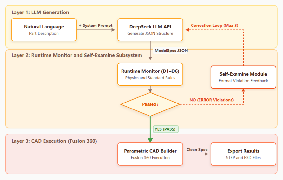
FMforME employs a three-layer pipeline architecture, illustrated in Figure 1. Data flows sequentially from natural language input through LLM generation, runtime constraint verification, and CAD execution, with a feedback loop from Layer 2 back to Layer 1 when violations are detected.
Layer 1—LLM Generation. An LLM backend receives a natural language part description and a structured system prompt containing ten physical validity rules. The system prompt explicitly specifies: Poisson ratio must be strictly within (0, 0.5), Young’s modulus must use GPa units (not Pa), density in kg/m3, yield strength must be less than tensile strength ( σ y < σ u t s ), all dimensions must be positive, boundary condition nodes must differ from load application nodes, and at least one boundary condition must specify type = "fixed" covering all six rigid-body degrees of freedom. For each backend, the API is called with structured JSON output enforcement and temperature = 1.0 to promote output diversity [41]. The output is a ModelSpec JSON object whose required interface fields are summarized in Table 1; the complete JSON example is provided in Supplementary Material. The contract includes part_type, dimensions, material, boundary_conditions, loads, and mesh.
The Monitor will then validate each field against the six defect predicates: poisson_ratio is checked to be within ( 0 , 0.5 ) (D5), dimensions are verified positive (D2), boundary-condition coverage is assessed (D1), load and BC node sets are checked for conflicts (D4), mesh element type and quality are validated (D6), and geometric ratios are checked for stress concentration risks (D3). If any ERROR-level violation is detected, the Self-Examine feedback loop triggers and the LLM receives a structured correction prompt; an illustrative feedback message is provided in Supplementary Material.
For controlled experiments, the generator supports seeded defect injection: after JSON generation, a specified field path (e.g., material.poisson_ratio) is overwritten with a controlled invalid or degraded value. For scalar and local defects (D1, D2, D3, D5, and D6), the injected field directly determines the target condition. For the relational D4 load–boundary-condition conflict, the injection is additionally audited after generation by checking whether the resulting load and boundary-condition node sets actually intersect.
Layer 2—Runtime Monitor. The Monitor executes six defect detection predicates (D1–D6) in priority order D5 → D4 → D1 → D2 → D3 → D6. This order reflects detectability and engineering importance: material violations (D5) are the most common AI errors and should be caught first [2]. Each predicate outputs Violation objects containing defect ID, severity (ERROR or WARN), human-readable description, the JSON field path of the violation, the actual value, and an engineering standard reference. The aggregated ViolationReport includes a boolean passed flag: any ERROR-level violation causes the report to fail.
Layer 3—CAD Execution. Validated specifications are written to a shared bridge directory (~/fusion_bridge/clean_spec.json). A Fusion 360 add-in written in Python 3.12.2 continuously monitors this directory. Upon detecting a new specification, it constructs parametric solid models using Autodesk Fusion 360 build v.2703.1.11 (May 2026 Product Update) and the native adsk.fusion API. Results are written back as result.json. The add-in uses a background thread for file-system polling combined with Fusion’s CustomEvent mechanism to ensure all API calls execute on the main thread [42].
The layer interface protocol is specified as follows. During LLM generation, the input is a natural-language part request plus the structured system prompt, and the expected output is a raw JSON string conforming to the ModelSpec contract. Empty or malformed responses are recorded as SYSTEM-level parse failures and are not passed to the Monitor because no valid ModelSpec exists.
After parsing, the field normalization step converts the JSON object into a normalized ModelSpec dictionary. Missing optional containers are represented as empty dictionaries or arrays where possible, and variant field names are mapped to canonical keys before predicate evaluation. The Runtime Monitor then consumes the normalized ModelSpec and returns a ViolationReport containing passed, n_errors, n_warnings, and a list of violations. ERROR level violations block CAD execution and trigger Self-Examine, whereas WARN-only reports are logged and allowed to proceed.
For Self-Examine, the original prompt is combined with structured violation feedback and sent back to the LLM to generate a new ModelSpec candidate. The loop terminates when no ERROR remains or when the retry budget is exhausted. Finally, Monitor-passed specifications are written to clean_spec.json for Fusion 360 execution, and the CAD add-in writes the build outcome to result.json. CAD build failures, when they occur, are logged as Layer 3 failures rather than Monitor failures, keeping generation, verification, and CAD build failure modes distinguishable.
The complete control flow of this interface is summarized in Protocol Box 1. It makes explicit which layer produces each artifact, which return paths are blocking, and where parse, verification, retry, and CAD execution failures are separated.
  • Protocol Box 1. Layer-level execution protocol and exception paths in FMforME.
  • Input: natural-language request P, retry budget R
  • Output: SUCCESS, SYSTEM_ERROR, SELF_EXAMINE_FAILED, or CAD_ERROR
  • prompt <- build_system_prompt(P)
  • last_report <- null
  • for attempt~=~0 … R:
  •    raw <- Layer1_LLM.generate(prompt)
  •    if raw is empty or not valid JSON:
  •       return SYSTEM_ERROR(parse_failure, raw)
  •    spec <- normalize(parse_json(raw))
  •    report <- Layer2_Monitor.check(spec)
  •    last_report <- report
  •    if report.n_errors > 0:
  •       if attempt == R:
  •          return SELF_EXAMINE_FAILED(report)
  •       prompt <- append_violation_feedback(prompt, report)
  •       continue
  •    write_json("clean_spec.json", spec)
  •    result <- Layer3_Fusion360.build("clean_spec.json")
  •    if result.success:
  •      return SUCCESS(spec, report, result)
  •    else:
  •      return CAD_ERROR(result)
  • return SELF_EXAMINE_FAILED(last_report)

2.3. Defect Detection Predicates (D1–D6)

The six defect predicates form the core of the Monitor’s verification logic. Table 2 summarizes the taxonomy with engineering standard references.
The use of six predicates was not arbitrary. Candidate checks were included only when they satisfied four criteria: (1) the defect can cause CAD construction failure, singular or ill-conditioned FEA models, or physically unreliable downstream interpretation; (2) the defect can be evaluated deterministically from ModelSpec fields before CAD execution; (3) the rule has support from engineering standards, numerical-analysis theory, CAD/FEA quality-control literature, or documented LLM engineering failure modes; and (4) the defect represents a distinct failure dimension rather than a minor variant of another rule. Fewer predicates would merge materially different failure mechanisms—for example, treating material admissibility, boundary-condition sufficiency, and mesh topology as one generic validity check would make the feedback less actionable for Self-Examine correction. Conversely, adding many narrowly specialized predicates at this stage, such as manufacturability tolerances, assembly interference, contact definitions, fatigue design codes, or domain-specific safety factors, would require part- or industry-specific assumptions that are not consistently available in the current ModelSpec and would reduce portability across the tested component families. The resulting six predicates therefore provide a deliberately compact middle ground: they cover boundary completeness, dimensional validity, geometric stress-risk features, load–constraint consistency, material admissibility, and mesh topology while leaving manufacturing, assembly, and domain-code checks for future extensions.
D1—Unconstrained Degrees of Freedom. This predicate addresses rigid body motion, the fundamental FEA error in which insufficient boundary conditions leave the stiffness matrix K singular. If no boundary conditions are defined, D1 raises an ERROR. For non-fixed constraints, the Monitor enumerates missing translational and rotational DOF and reports a WARN. In the current implementation, a type = "fixed" constraint is treated as strong evidence of full support, an abstraction whose boundary is examined in the controlled boundary-case analysis below [37,38].
D2—Negative Stiffness. Per Bathe’s FEM theory [37], the stiffness matrix K requires positive definiteness. Zero or negative cross-sections produce non-positive entries on K ’s diagonal, leading to solver failure or unphysical displacements. D2 scans all scalar dimension fields (nominal_diameter, thickness, bore_diameter, outer_diameter, ball_diameter, etc.). Negative values always trigger ERROR. Zero values trigger ERROR for structurally critical parameters and WARN for secondary parameters. For shaft-type parts, adjacent segment diameter ratios exceeding 10:1 trigger WARN, as extreme cross-section changes produce stress concentration [39].
D3—Stress Singularity. Based on classical linear elastic fracture mechanics [39], D3 detects geometric features that cause unbounded stress in linear elastic FEA. For all part types: zero fillet radius at re-entrant corners triggers WARN (elastostatic stress at a mathematically sharp corner is theoretically infinite); mesh maximum aspect ratio exceeding 50 triggers WARN. For ball bearings specifically, six additional rules apply: ball_count = 0 triggers ERROR (no load transfer path); ball_count < 3 triggers WARN; ball_diameter  0 triggers ERROR; ball_diameter exceeding the radial gap between inner and outer races triggers ERROR (ball cannot physically fit); ball_diameter exceeding 80% of radial gap triggers WARN (insufficient raceway wall thickness); and bore_diameterouter_diameter triggers ERROR (impossible bearing geometry per ISO 15 [43]).
D4—Load-Boundary Condition Conflict. Per ASME V&V 10-2019 Section 5.1 [38], a load applied at a constrained node is absorbed by the constraint and contributes nothing to the structural response. D4 computes the set intersection of node identifiers appearing in both boundary_conditions and loads arrays and reports a WARN for any conflict.
D5—Material Property Violation. This is typically the most frequently triggered predicate, as LLMs commonly generate physically impossible material parameters [2,3]. Default material bounds—derived from standard engineering references [44]—are: E ( 0.001 , 1000 ) GPa, ν ( 0 , 0.5 ) (strict thermodynamic constraint), ρ (100, 25,000) kg/m3, σ y ( 1 , 5000 ) MPa, σ u t s ( 1 , 6000 ) MPa. The first three parameters trigger ERROR when out of range, while isolated yield-strength or tensile-strength range violations trigger WARN because they may reflect material-selection uncertainty. The cross-field consistency check σ y < σ u t s is stricter: if yield strength is not lower than ultimate tensile strength, D5 reports an ERROR because the material model is physically inconsistent.
D6—Mesh Topology Error. This predicate validates mesh quality against the Verdict geometric quality library [40], which operationalizes Knupp’s algebraic mesh quality metrics [45]. A negative or zero minimum Jacobian determinant indicates inverted or degenerate elements and triggers ERROR. Values below 0.3 and 0.5 trigger progressively less severe WARN messages. Element types are checked against the canonical set {tet4, tet10, hex8, hex20, shell3, shell4, wedge6}; solver-specific aliases such as C3D8R are logged as WARN rather than blocked, because they are representation mismatches rather than necessarily invalid meshes.

2.4. Self-Examine Correction Mechanism

The Self-Examine subsystem implements an iterative refinement loop, adapting the Self-Refine paradigm [16] and the ReAct reasoning-acting framework [17] for use in the engineering domain. Unlike generic self-refinement approaches, the engineering context demands that feedback be (1) grounded in verifiable standards, (2) cite specific JSON field paths, and (3) provide actionable parameter-level guidance. The CRITIC framework’s insight [18]—that external, deterministic verification signals are more reliable than self-evaluation—is directly applicable here: our Monitor serves as the external verifier, generating deterministic violation reports that guide the next LLM attempt.
When the Monitor reports failure, the format_violation_feedback() function constructs a structured correction prompt containing five sections: (i) a header indicating rejection by the Runtime Monitor; (ii) a list of CRITICAL ERRORS, each annotated with defect ID (D1–D6), natural language description, the violating JSON field path, the actual value, and the engineering standard reference (e.g., ASME V&V 10-2019 Section 4); (iii) a list of WARNINGS with identical annotation; (iv) a FIX INSTRUCTIONS section providing specific, actionable guidance for each defect type (e.g., “D5: ensure poisson_ratio is strictly between 0 and 0.5; for steel, use 0.3”); and (v) an output format reminder. The feedback is appended to the original system prompt and the LLM regenerates the entire ModelSpec.
The loop continues until either the specification passes (no ERROR-level violations) or the maximum retry count (3, corresponding to one initial attempt plus up to three correction cycles) is exhausted. Per the diminishing-returns pattern documented by Madaan et al. [16], the majority of improvements occur within the first 1–2 refinement steps.
The retry-limit choice was evaluated empirically using the recorded Self-Examine histories. For V4-Flash, 54 cases triggered correction: 49 were resolved on the first retry, an additional 3 on the second retry, and no additional success was observed on the third retry. The two cases that exhausted all three retries continued to report ERROR-level boundary-condition coverage issues across attempts, with load/support consistency warnings appearing in the same specifications. For V4-Pro and Qwen 3.6 Flash, all 46 triggered cases in each backend were corrected within a single retry. Gemini 3.5 Flash triggered correction in 47 cases: 46 were resolved on the first retry and one additional case was resolved on the second retry. These distributions support max_retries = 3 as a bounded cost setting that captures the observed correction gains while retaining a small margin for difficult multi field cases.
Table 3 summarizes the sensitivity analysis based on recorded Self-Examine histories. Setting the retry budget to one correction cycle already captures nearly all observed gains. In V4-Flash, 49 of 54 triggered cases were fixed after one correction cycle, while 3 additional cases required a second cycle; in Gemini 3.5 Flash, 1 of the 47 triggered cases also required a second cycle. Allowing a third correction cycle did not recover any additional successful case in the recorded histories.
The two permanent V4-Flash failures were further inspected to clarify why additional retries did not resolve them. Both cases remained blocked by D1 boundary-condition coverage after three correction attempts. The failed revisions did not require changing a single scalar value; instead, they required coordinated changes across the boundary-condition array, explicit degree-of-freedom coverage, and in one case the load/support node-set relation. This explains why the field-level feedback was sufficient for scalar material, dimensional, and mesh corrections but less effective for these multi-field constraint repairs. Table 4 summarizes these two cases.

2.5. Fusion 360 CAD Execution Layer

The Fusion 360 add-in implements parametric solid modeling for three part types using the native adsk.fusion Python API [42]. All models are constructed in centimeter-scale units (scale factor 0.1) to align with Fusion 360’s default coordinate system.
ISO 4762 Hex Socket Bolt. A six-sided regular polygon sketch centered at the origin is extruded to form the bolt head, followed by a 45° chamfer applied to the head’s top edge [46]. A cylindrical sketch for the shank is extruded in the opposite direction and joined to the head body. Material is assigned from the Fusion material library via fuzzy name matching against the specification’s material name [42].
L-Bracket. An L-shaped profile sketch consisting of six points defining the bracket’s outer contour is drawn on the XY plane. An inside-corner fillet is added at the bend intersection. The profile is extruded to the specified thickness. Four mounting holes (3 mm radius, M6 clearance) are created as cut extrudes positioned at the midpoint and offset positions of both legs. Edge fillets (1 mm radius) are applied to all boundary edges exceeding 0.5 mm length.
ISO 15 Deep Groove Ball Bearing. Outer and inner rings are created as concentric cylindrical extrusions with symmetric extent about the XY plane. A single rolling element is generated by revolving a half-circle sketch (a 180° arc closed by a line segment) around the closing line. This critical design choice avoids the classic profile-crosses-axis error in Fusion 360’s ASM geometric kernel. The resulting spherical body is replicated N times via a circular pattern around the Z-axis (bearing rotation axis). This approach correctly produces an evenly spaced ring of rolling elements between the inner and outer races [43].

2.6. Experimental Design

A total of 141 test cases were designed and executed for each of four LLM backends, yielding 564 total test executions across the experiment. The test suite comprised two complementary groups, with each seeded defect configuration repeated twice ( n = 2 replicates) to assess detection consistency.
Seeded Defect Tests (96 cases per model). After LLM generation, a controlled defect condition is injected into the ModelSpec JSON at a specified field path (e.g., injecting poisson_ratio = 0.6 for a D5 material violation test). For scalar or local predicates, the injected value directly creates the target invalid or degraded condition. For D4, which depends on the relation between loads and boundary_conditions, the attempted injection is audited by recomputing the node-set intersection after injection; only cases in which an intersection is actually present are treated as realized D4 conflicts for Monitor detection scoring. The test is scored as a successful detection if the expected realized defect type appears in the Monitor’s violation list for the first (pre-correction) generation attempt. A total of 48 unique seeded configurations were designed, with each configuration repeated twice ( n = 2 replicates), yielding N = 96 seeded trials per model. The 48 configurations were evenly distributed across the six defect types (8 unique configurations per defect type × 2 replicates = 16 trials per defect). To ensure coverage of distinct geometric contexts, the configurations within each defect type were assigned to the three part types in proportion to their physical relevance: for example, D3 (stress singularity) configurations emphasized ball bearings and L-brackets where fillet radii and geometric ratios are critical, while D4 (load-BC conflict) configurations spanned all three part types. A complete listing of all 48 seeded configurations with their defect types, injected field paths, part-type assignments, and expected severity levels (ERROR/WARN) is provided in the accompanying data repository.
The 48 configurations were generated using the seeded injection logic implemented in the FMforME test pipeline rather than by random sampling. Each configuration specifies five items: a defect category (D1–D6), a target ModelSpec field path, an injected value or replacement rule, an expected severity level (ERROR or WARN), and the applicable part family. The LLM first generates a baseline ModelSpec; the injector then overwrites the selected JSON field to create a controlled invalid or degraded specification. The seeded detection score is therefore computed on the injected first attempt ModelSpec, allowing the same engineering failure mode to be tested across different LLM baseline outputs.
The 48 unique configurations follow a balanced coverage design: each of the six defect families contains eight configurations. Within each family, the configurations vary the field path, perturbation magnitude, severity level, and part relevance. For example, D5 covers material fields such as Poisson’s ratio, Young’s modulus, density, and strength consistency; D1 covers absent boundary conditions, partial DOF constraints, and nominal fixed constraints with incomplete DOF information; D4 covers node set conflicts between loads and boundary_conditions; D2 and D3 cover invalid dimensions, geometric ratios, fillet radius, and bearing feasibility constraints; and D6 covers element type vocabulary, minimum Jacobian, and aspect ratio.
The selection criteria were informed by both recent LLM assisted engineering studies and conventional CAD/FEA quality control. Alexiadis and Ghiassi showed that LLMs can drive geometry and mesh generation as well as multiphysics setup, while still encountering errors in complex geometry and boundary definition [3]. Shafiq et al. reported performance differences across LLMs in geometry generation, Boolean operations, simulation file completeness, material properties, and boundary conditions [2]. Baker et al. identified weak spatial and geometric reasoning as a major bottleneck for LLMs in mechanical engineering [11]. In parallel, the CAD quality taxonomy of Gonzalez-Lluch et al. provides a basis for relating geometric, topological, and semantic model quality issues to downstream CAD reliability [23]. Thus, the seeded suite should be interpreted as a structured coverage sample of known CAD/FEA failure modes, not as a random sample of all possible LLM errors; broader statistical representativeness would require larger logs of naturally occurring LLM-CAD failures.
To make this representativeness claim more explicit, the 48 configurations should be read as a safety-coverage benchmark rather than as an empirical frequency model. External quantitative benchmarks support this coverage-oriented interpretation. Shafiq et al. reported solver-input success rates of 78–88%, but only 70% success for simple geometry generation, 56% for assembly geometry generation, and no successful Boolean-operation implementation in their evaluated assembly tasks [2]. FEABench similarly shows that even tool-using LLM agents do not always produce executable engineering API calls, with the best reported strategy reaching 88% executable COMSOL API generation [14]. Text2CAD-Bench provides a larger text-to-parametric-CAD reference set of 600 human-curated examples and reports that performance degrades substantially as topology and CAD-feature complexity increase [15]. The present natural-generation logs provide an internal quantitative check on this coverage: across 180 natural tests, D6 terminology or mesh warnings appeared 133 times, D1 boundary-condition warnings or errors appeared 31 times, one D4 load–support warning appeared, and V4-Pro produced 14 pre-Monitor parse failures. In contrast, D2, D3, and D5 did not appear spontaneously in the 45 natural tests per model, but they were retained in the seeded suite because invalid dimensions, stress-concentration geometry, and material-property violations are well-established high-consequence CAD/FEA failure modes. Therefore, the seeded suite combines observed natural LLM-CAD failure modes with safety-critical but less frequent engineering invalidities, while not claiming to reproduce the population frequency of real-world LLM-CAD errors.
Natural Generation Tests (N1–N45, 45 cases per model). Fifteen independent natural generation runs were performed for each of the three part types (bolt, L-bracket, and ball bearing), yielding 15 × 3 = 45 natural tests per model. No manual modification was applied to these specifications. The natural generation design uses the same number of trials for all three component families to avoid part-type bias in the reported natural issue rate and pass-rate estimates. These tests serve two purposes: measuring the frequency with which LLMs spontaneously produce specifications containing WARN or ERROR violations or unparseable outputs, and assessing cross-model differences in output quality under identical prompting and decoding conditions.
Test Execution Procedure. The LLM calls, seeded defect injection, Monitor evaluation, Self-Examine retries, result logging, and metric aggregation were executed by the experimental Python pipeline. No manual visual judgment was used to decide whether a predicate detected an injected defect; detection was scored by matching the expected seeded defect label against the Monitor’s first-attempt violation report. For Layer 3, Fusion 360 imposes an application-level execution constraint: the CAD add-in must be started inside the Fusion 360 environment before it can receive events through the Autodesk API. Once the add-in is active, it automatically reads each Monitor-approved clean_spec.json, constructs the parametric model through the Fusion API, and writes the build outcome to result.json. Thus, the experimental detection, correction, and scoring stages are algorithmic, while the Fusion-side launch requirement reflects the host Autodesk Fusion 360 CAD software environment (build v.2703.1.11, May 2026 Product Update).
Statistical Methodology. For each defect category and overall detection rate, Wilson score 95% confidence intervals were computed (suitable for binomial proportions, particularly near 0 or 1). Because the Monitor is deterministic rather than a stochastic classifier, reliability is assessed through observed detection rates, confidence intervals, parse-failure rates, boundary-case analysis, and downstream Fusion 360 build outcomes rather than through chance-level significance tests.
The experiment configuration evaluated four LLM backends: DeepSeek-V4-Flash, DeepSeek-V4-Pro, Qwen 3.6 Flash, and Gemini 3.5 Flash. These are the model versions used throughout the experiment and reported in the corresponding execution logs. The experimental pipeline used Python 3.12.2, and Layer 3 used Autodesk Fusion 360 build v.2703.1.11 (May 2026 Product Update). All four backends used temperature 1.0 and max_tokens = 2048; Self-Examine was enabled with max_retries = 3; and the Monitor operated in non-strict mode, in which critical physical violations are classified as ERROR and borderline cases as WARN. These backends were selected because they were accessible during the project, supported structured JSON generation or OpenAI compatible calling conventions, and represented practical deployment profiles spanning low-latency, larger Pro-tier, OpenAI-compatible, and independent third-party model-family settings. From an engineering deployment perspective, DeepSeek and Qwen style models are attractive because of their relatively low operating cost and the availability of deployment paths that are more compatible with private or on premise engineering data workflows than closed cloud only models; Gemini 3.5 Flash provides an independent cross-family reference point within the same benchmark design. The goal of the experiment was to verify that FMforME can operate as a backend-independent verification layer across different API interfaces and output behaviors, rather than to rank all available LLMs. Broader evaluation on GPT, Claude, and additional local or proprietary model families remains future work. Extending the comparison to GPT, Claude, and other proprietary or local model families would require the same balanced benchmark design, including identical seeded configurations, natural prompts, retry settings, parse-failure accounting, Fusion 360 execution procedure, and latency logging. The present four-backend experiment should therefore be interpreted as an initial cross-interface validation of the framework rather than as a comprehensive model leaderboard. Layer 1 was invoked for all 564 test cases. Parseable outputs proceeded to Layer 2 Monitor verification and Self-Examine correction when required, while Monitor-passed specifications proceeded to Layer 3 Fusion 360 parametric modeling. All experiments were conducted on a Windows 11 system with an Intel Core i7 processor and 16 GB RAM. The complete source code and experimental data are available in the accompanying repository.


3. Results

3.1. Overall Performance

Table 5 presents aggregate results across all four LLM backends for the 141 test cases per model. The true detection rate is computed from the initial generation attempt, as the subsequent Self-Examine process is explicitly designed to eliminate injected defects. Wilson 95% confidence intervals are reported for proportion metrics to show the uncertainty associated with finite sample sizes.
The aggregate results indicate that FMforME’s realized seeded detection performance was similar across the four LLM backends, ranging from 95.5% to 95.8% with overlapping Wilson intervals. Therefore, the small numerical advantage of Qwen should not be interpreted as a statistically established superiority in Monitor detection. The more important pattern is categorical: scalar or local predicates such as D2, D3, D5, and D6 were consistently detected once realized, whereas boundary-condition-related predicates require separate interpretation. D1 remains a Monitor abstraction boundary because it depends on multi-field constraint sufficiency, while D4 is a relational injection-realization issue because a load–support conflict exists only when the injected and generated node sets actually intersect.
For the Self-Examine correction process, Qwen 3.6 Flash achieved the highest proportion of direct passes (67.4%, 95/141), followed closely by Gemini 3.5 Flash (66.7%, 94/141), V4-Pro (63.8%, 81/127 evaluable), and V4-Flash (61.7%, 87/141). Self-Examine corrected an additional 36.9% (V4-Flash), 36.2% (V4-Pro), 32.6% (Qwen 3.6 Flash), and 33.3% (Gemini 3.5 Flash) of test cases, respectively. V4-Flash was the only model to exhibit permanent Self-Examine failures (2/141, 1.4%), both of which occurred in seeded defect tests where the LLM failed to resolve ERROR-level D1 boundary-condition coverage violations within the maximum retry budget; load/support consistency warnings were also present in these cases. V4-Pro had 14 tests (9.9%) that could not be evaluated through the full pipeline due to unparseable LLM JSON output—a failure mode absent in V4-Flash, Qwen 3.6 Flash, and Gemini 3.5 Flash.
Natural generation tests revealed differences in output quality across backends. V4-Flash, Qwen 3.6 Flash, and Gemini 3.5 Flash all showed an observed 100% natural pass rate in this 45-case benchmark, with 95% CI lower bounds of 92.1%. For V4-Flash, 6 of the 45 natural tests triggered the Self-Examine loop and all 6 were corrected. Qwen 3.6 Flash required no Self-Examine corrections in natural tests, while Gemini 3.5 Flash passed after correction but produced WARN-level issues in all 45 natural tests. V4-Pro, by contrast, achieved a 75.6% pass rate [61.3%–85.8%], with 11 of 45 natural tests failing before the Monitor stage due to unparseable LLM JSON output (SYSTEM errors). The natural issue rate, defined as tests with WARN-level Monitor reports or pre-Monitor parse failures, was 60.0% for V4-Flash, 68.9% for Qwen 3.6 Flash, 80.0% for V4-Pro, and 100.0% for Gemini 3.5 Flash; the Gemini value reflects pervasive WARN-level D6 terminology mismatch and D1 boundary-condition warnings rather than end-to-end build failure.
The 14 V4-Pro parse failures (9.9% of all V4-Pro tests) were examined separately because they occurred before any Monitor predicate could be evaluated. Nine failures were empty responses and five were malformed or truncated JSON strings. A diagnostic parse-reliability check under the same prompts and decoding settings captured 27 attempts across representative failed cases: 10 parsed successfully, 13 returned empty responses, and 4 produced truncated or syntactically invalid JSON. Because V4-Flash, Qwen 3.6 Flash, and Gemini 3.5 Flash used the same experimental settings and produced zero parse failures, the evidence points to a V4-Pro structured-output reliability issue under the tested configuration, although provider-side API behavior and prompt–model interaction cannot be completely ruled out. For metric interpretation, parse failures are excluded from Self-Examine denominators because no ModelSpec exists to correct, but they are counted as end-to-end pipeline failures for natural pass rate and Fusion build success.
The average Monitor time was small for all four models (∼0.1 ms per in-memory check), indicating that rule-based predicate evaluation contributed little to the recorded pipeline time. V4-Pro’s total pipeline time (8015.8 s) was approximately 4.5× greater than the fastest model (Qwen 3.6 Flash, 1779.6 s), while Gemini 3.5 Flash occupied an intermediate wall-clock profile (4437.9 s). The recorded LLM-call latency diagnostics also show that V4-Pro and Gemini responses were slower and more variable than the two Flash-tier DeepSeek/Qwen backends, although the latency summaries and Self-Examine attempt counts are reported as separate diagnostics because parse-failure cases did not always produce a complete correctable ModelSpec history.
Fusion 360 Layer 3 results support the Monitor’s predictive validity for the evaluated part families: across all four models, every specification that passed Monitor checks successfully built in Fusion 360 (548/548, 100%). The two V4-Flash non-builds correspond to the two permanent Self-Examine failures (blocked by Monitor), and V4-Pro’s 14 non-builds correspond entirely to unparseable LLM JSON output. Qwen 3.6 Flash and Gemini 3.5 Flash each achieved 141/141 build success. This result supports using the six defect predicates as a practical gatekeeper for CAD executability in this benchmark, while not implying complete coverage of all possible CAD modeling failure modes.

3.2. Defect Detection Analysis

Table 6, Table 7, Table 8 and Table 9 report per-defect realized seeded detection rates with Wilson 95% confidence intervals for each model. Table 6 presents the DeepSeek-V4-Flash results.
For V4-Flash, D2, D3, D5, and D6 each reached 16/16 detection in the seeded trials, with Wilson lower bounds of 80.6%. D1 recorded 75.0% detection (12/16), reflecting the greater difficulty of boundary-condition sufficiency reasoning. D4 was detected in all 12 realized load–support conflicts (100.0%, 12/12); the remaining four D4 attempts did not actually create a node-set intersection after injection. The realized overall detection rate was 95.7% [89.3–98.3%].
Table 7 presents the DeepSeek-V4-Pro results.
V4-Pro detected 16/16 seeded cases for D2, D3, D5, and D6 in the seeded sample, with lower D1 detection (73.3%, 11/15). D4 was detected in all 12 realized load–support conflicts (100.0%, 12/12). The realized Monitor-evaluable overall rate was 95.6% (87/91). The three seeded parse failures are instead counted in the separate output-format reliability analysis because the Monitor had no valid ModelSpec on which to operate.
Table 8 presents the Qwen 3.6 Flash results.
Qwen 3.6 Flash achieved the highest observed numerical realized overall detection rate at 95.8% (92/96). It was also the only model in which all 16 attempted D4 injections realized an actual load–support intersection, and all 16 were detected. D1 was 75.0% (12/16), consistent with the other evaluated backends. D2, D3, D5, and D6 were also detected in all 16 seeded cases, with the finite-sample uncertainty reflected by the Wilson intervals.
Table 9 presents the Gemini 3.5 Flash results.
Gemini 3.5 Flash showed observed complete detection for D2, D3, D5, and D6 in this finite seeded sample, and matched the other models on D1 at 75.0% (12/16). Its D4 attempted-injection realization rate was lower than the other models (8/16), but all 8 realized load–support conflicts were detected by the Monitor. The realized overall detection rate was therefore 95.5% (84/88), indicating that the low attempted D4 count reflects injection realization rather than a D4 predicate miss.
For all four tables, detection rate denotes the proportion of seeded defects correctly flagged by the Monitor at first generation attempt. The Wilson confidence intervals are emphasized because the Monitor is a deterministic rule engine and the seeded sample size is limited.
The Wilson confidence intervals reported in Table 6, Table 7, Table 8 and Table 9 show that the intervals for D1, D4, and Overall overlap substantially, so inter-model differences should be interpreted cautiously. D2, D3, D5, and D6 reached 16/16 detection in this seeded sample for all four backends, suggesting that the corresponding dimensional, material, and mesh predicates were less sensitive to the tested LLM output variations than D1. For D4, the reported denominator is the number of attempted D4 injections that actually produced a load–boundary-condition node-set intersection, as summarized in Table 10. The finite sample size should be kept in mind, as the Wilson lower bound for a 16/16 result is 80.6%.
D1 remained more difficult than scalar or local checks such as D2, D5, and D6 because it evaluates the sufficiency of the boundary-condition system as a whole. Unlike a material bound or a mesh-quality threshold, unconstrained DOF detection requires interpreting whether the specified supports actually prevent rigid-body motion across translational and rotational degrees of freedom. An empty boundary-condition list is an unambiguous ERROR, but partial DOF coverage, inconsistent type/dof combinations, and model-specific node-set conventions are more ambiguous and are conservatively reported as WARN. In particular, the current Monitor treats the presence of a type = "fixed" boundary condition as strong evidence of constraint coverage when the specification does not explicitly enumerate all constrained DOF. Therefore, some seeded D1 cases that still contain a nominal fixed boundary condition are recognized as boundary-condition issues but are not always classified as first-attempt ERROR detections. The lower D1 detection rate across all four models therefore reflects a real limitation of the current abstraction: D1 is not a single-field validity check, but a relational judgment over constraint type, constrained DOF, and node-set convention.
The D4 result should be interpreted differently from the D1 result. The Monitor’s D4 predicate is deterministic: if the load node set and boundary-condition node set intersect, the conflict is flagged as WARN. A post-injection replay audit confirmed that every realized D4 conflict was detected by the Monitor (12/12 for V4-Flash, 12/12 for V4-Pro, 16/16 for Qwen 3.6 Flash, and 8/8 for Gemini 3.5 Flash). The variation lies in D4 realization rather than D4 predicate sensitivity: some attempted D4 injections did not create an actual intersection with the independently generated counterpart node set. Qwen 3.6 Flash produced realized intersections in all 16 D4 attempts, whereas Gemini 3.5 Flash produced realized intersections in 8 of 16 attempts. Thus, D4 exposes a limitation of the seeded defect generation protocol: relational defects should be verified after injection before being used as Monitor ground truth. Future seeded D4 tests should bind the injected node set to node identifiers first generated by the LLM, ensuring that every attempted D4 case contains a verified load–support intersection before Monitor evaluation.
A controlled Monitor boundary-case analysis was conducted to examine the decision boundaries of the D2–D6 results. This analysis is not included in the main statistical benchmark; instead, it probes the six predicate families using 12 controlled boundary-case ModelSpec inputs designed around strict physical limits, near-threshold numerical values, cross-field semantic conflicts, and representation mismatches. The boundary suite produced four ERROR-blocked cases, seven WARN-only pass cases, and one clean pass, covering all six predicate families (D1–D6). The scripts and resulting JSON/CSV summaries are provided in the accompanying repository.
The interpretation of Table 11 is as follows. Strict physical invalidity cases, including absent boundary conditions, zero structural thickness, Poisson’s ratio at 0.5, and yield strength not lower than tensile strength, were blocked as ERROR. Near-threshold geometry, semantic load/support conflicts, mesh-quality margins, and solver-specific element aliases were retained as WARN because they may remain CAD-buildable or solver-dependent. The single clean-pass case is also informative: it shows that the current D1 implementation treats a fixed boundary-condition label as strong evidence of full constraint coverage even when the explicit DOF list is incomplete. This motivates a future consistency check requiring fixed constraints to agree with explicit DOF enumeration.
Table 12, Table 13, Table 14 and Table 15 present the natural generation defect distribution disaggregated by part type for each model.
For Table 12, Table 13, Table 14 and Table 15, Pass % denotes the proportion of natural tests with zero ERROR-level violations in the final post-Self-Examine specification. D1 W/E counts warning and error instances together, while D6 WARN counts warning-level mesh or element-type findings. Columns D1–D6 count violation instances, not unique tests; one generated specification may contribute multiple warning or error events of the same defect type, so some counts exceed N = 15 . For V4-Pro, six bolt tests and five L-bracket tests failed before Monitor evaluation because of unparseable JSON; therefore, D1–D6 counts for those rows are computed only over evaluable outputs, while the reported pass rates retain the full natural-test denominator to reflect end-to-end pipeline behavior.
Across the four-model natural generation results, D6 appeared 133 times, with Gemini contributing 45 D6 warnings across 45 natural runs. This pattern strengthens the interpretation that many D6 events reflect vocabulary alignment rather than severe mesh failure, particularly when models emit solver-specific element identifiers such as Abaqus-style element names. D1 represents a different difficulty: relational reasoning over boundary-condition coverage and node-set consistency. The natural-generation defect pattern should therefore be interpreted as a combination of terminology mismatch (D6), multi-field constraint reasoning (D1), model-specific node conventions, and V4-Pro-specific structured-output reliability issues.

3.3. Self-Examine Correction Performance

The Self-Examine results indicate that most correctable engineering errors were resolved quickly once the Monitor supplied field-level feedback. Qwen 3.6 Flash corrected all 46 intercepted specifications, as did V4-Pro for its 46 evaluable intercepted specifications. Gemini 3.5 Flash corrected all 47 intercepted specifications, with one case requiring a second correction cycle. V4-Flash corrected 52 of 54 intercepted specifications (96.3%), with 2 permanent failures where the LLM was unable to resolve ERROR-level D1 boundary-condition coverage violations within the maximum 3-retry budget. The key implication is that Self-Examine is effective for scalar or localized violations, but remains less reliable when the repair requires coordinated changes across boundary-condition and load arrays. D4 load/support conflicts, when present, remained WARN-level findings and did not themselves trigger Self-Examine.
The correction histories show a clear diminishing-return pattern. As shown in Table 3, nearly all correction gains were captured within one retry. Only three V4-Flash test cases and one Gemini test case required a second correction cycle, and the third cycle did not recover any additional cases. This distribution aligns with Madaan et al.’s [16] finding that most self-refinement gains occur within the first iteration, with diminishing returns thereafter, and supports using a small retry budget for cost-controlled engineering workflows.
The two V4-Flash permanent failures represent an important boundary condition for the Self-Examine approach. In both cases, the blocking error was D1 boundary-condition coverage, and the required correction involved coordinating multiple JSON array fields rather than adjusting a single scalar parameter. This suggests that the current field-path-level feedback format, while sufficient for scalar and single-array corrections, may benefit from cross-field relationship guidance when violations span multiple interdependent specification components.
It is important to distinguish the Monitor’s detection rate from the rate at which Self-Examine correction is triggered. The Monitor reports violations at two severity levels: ERROR (triggering the Self-Examine feedback loop and blocking downstream CAD execution) and WARN (logged but not blocking). As described in Section 2.2, defects D4 (load-BC conflict) and D2 (zero secondary dimensions) are classified as WARN in their default configurations, meaning they appear in the violation list but do not activate the correction loop. Consequently, the number of seeded test cases that triggered Self-Examine correction is smaller than the number of cases in which the defect was detected. For V4-Flash, 88 of 92 realized seeded defects were detected in the first-generation violation list (95.7%), of which 48 contained at least one ERROR-level violation and entered the Self-Examine loop; the remaining 40 detections were WARN-only and did not trigger correction. The remaining 6 Self-Examine triggers (out of the 54 total) originated from natural generation tests where the LLM spontaneously produced ERROR-level violations (D1 or D6); all 6 were corrected by Self-Examine and passed the Monitor in this benchmark. This distinction between detection sensitivity and correction activation should be considered when interpreting the framework’s overall behavior: high detection sensitivity captures a broad range of specification quality issues, while the ERROR/WARN threshold determines which issues are deemed severe enough to warrant iterative LLM correction.
Because the ERROR/WARN boundary is a design choice, its sensitivity was evaluated using first-attempt violation logs. Table 16 compares the current policy with two extreme alternatives: a conservative policy that upgrades all WARNs to ERROR, and a permissive policy that downgrades all ERRORs to WARN. The sensitivity analysis was computed by reclassifying the recorded first-attempt violation reports.
The conservative policy would substantially increase the Self-Examine workload by sending many WARN-only cases into correction, including representation-level D6 element-name aliases that may not be physically dangerous. Conversely, the permissive policy would allow currently blocked specifications to proceed without correction, including cases with absent boundary conditions, invalid dimensions, material-property violations, or invalid mesh conditions. The current policy therefore prioritizes blocking mathematically or operationally unsafe specifications while logging context-dependent cases for engineering review. Nevertheless, the analysis shows that the threshold is not universally optimal; production deployments should tune severity levels according to organizational risk tolerance, part criticality, and downstream solver requirements.
In terms of final system-quality indicators, the conservative policy would increase the correction workload from 54 to 124 cases for V4-Flash, from 46 to 117 evaluable cases for V4-Pro, from 46 to 123 cases for Qwen 3.6 Flash, and from 47 to all 141 cases for Gemini 3.5 Flash. This would greatly increase LLM calls without necessarily improving CAD buildability, because many additional triggers are D6 terminology warnings or other WARN-only cases. The permissive policy would have the opposite effect: it would remove all correction triggers, but it would also allow 54, 46, 46, and 47 currently blocked first-attempt specifications, respectively, to proceed without correction. The current policy is therefore selected as an engineering risk-control compromise rather than as an automatically optimized classifier. Automatic threshold learning would require a larger labeled dataset linking each warning and error type to downstream CAD, FEA, and engineering-review outcomes, which is beyond the present benchmark.

3.4. Fusion 360 Modeling Results

All four models executed the three-layer pipeline (LLM generation → Monitor → Fusion 360 CAD), with Layer 3 receiving every Monitor-passed specification for parametric modeling. Table 17 presents the Fusion 360 build results across 564 total test executions (141 per model).
Across all four models, every specification that passed Monitor checks successfully built in Fusion 360 within the evaluated benchmark, providing evidence that the Monitor’s pass/fail determination is a useful predictor of CAD buildability for these part families.
The two V4-Flash build failures correspond exactly to the two permanent Self-Examine failures (S26_r2 and S47_r2): these specifications were blocked by the Monitor and never reached Fusion 360. V4-Pro’s 14 non-builds correspond entirely to unparseable LLM JSON output—specifications that could not be evaluated by any layer of the pipeline. Qwen 3.6 Flash and Gemini 3.5 Flash each achieved a 141/141 build record, consistent with their 100% Monitor pass rate after Self-Examine and zero parse failures.
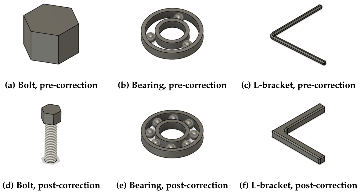
Figure 2 presents representative before–after CAD modeling examples selected from the experimental records. In the normal safety-gated pipeline, ERROR-level pre-correction specifications are blocked by the Monitor and are not forwarded to Fusion 360. The pre-correction panels are illustrative reconstructions from the recorded JSON outputs before Monitor-guided correction, while the post-correction panels show the corresponding Monitor-passed Fusion 360 models. These examples use the experimental settings described in Section 2.5 and illustrate how the framework changes under-specified or geometrically incomplete outputs into buildable CAD models.

3.5. Performance by Part Type

Table 18 disaggregates natural generation performance by part type and model, providing insight into part-specific LLM behavior.
A part-type effect was observed for V4-Pro, the only model with final natural-generation pass failures. Ball bearings achieved a 100% pass rate under V4-Pro, while bolts and brackets achieved 60.0% and 66.7%, respectively. These failures were driven by unparseable LLM output rather than by D1 violations: 6 of 15 bolt tests and 5 of 15 bracket tests generated empty, malformed, or truncated JSON that could not be evaluated by any pipeline layer. One possible explanation is that the bearing prompt supplied more standardized geometric structure (ISO 15 dimensions, raceway geometry), whereas bolt and bracket prompts elicited more varied output formats.
For V4-Flash, Qwen 3.6 Flash, and Gemini 3.5 Flash, natural pass rates were observed at 100% across all part types in this benchmark. The primary differentiator was D6 warning frequency: Gemini 3.5 Flash generated D6 warnings in all 45 natural tests, followed by Qwen 3.6 Flash (43), V4-Flash (26), and V4-Pro (19). These warnings were mainly due to solver-specific element identifiers rather than CAD build failure. L-brackets elicited the highest D6 frequency for V4-Flash and Qwen, whereas Gemini showed uniform D6 warning frequency across all three part types.
The seeded detection results by part type were consistent with the aggregate findings: D2, D3, D5, and D6 remained stable across part families, whereas D1 and D4 showed model-dependent variability that is consistent with node-ID assignment effects rather than with part geometry alone.

3.6. Timing and Computational Efficiency

Table 19 presents the pipeline timing breakdown for each model, with 95% confidence intervals for recorded LLM-call latencies and mean Monitor predicate-evaluation time. The timing table is reported separately from the Self-Examine attempt-count analysis because parse-failure cases do not yield a complete correctable ModelSpec history.
LLM generation dominated the time budget for all models, so deployment cost is governed primarily by backend latency rather than by the Monitor. V4-Flash and Qwen 3.6 Flash exhibited comparable recorded mean LLM-call latencies (4395 ms and 5286 ms, respectively), with Qwen 3.6 Flash showing lower variability (std 1953 ms vs. 2073 ms). Gemini 3.5 Flash was slower than these two Flash-tier backends (24,688 ms mean) but faster than V4-Pro, while V4-Pro was the slowest and most variable backend (48,011 ms mean; std 34,239 ms). This means that, in practical use, model choice affects responsiveness far more than adding runtime verification.
Total pipeline times were 1811.7 s (V4-Flash), 8015.8 s (V4-Pro), 1779.6 s (Qwen 3.6 Flash), and 4437.9 s (Gemini 3.5 Flash). The near-identical total times for V4-Flash and Qwen 3.6 Flash indicate that their end-to-end deployment cost was similar in this benchmark, whereas V4-Pro incurred the largest wall-clock cost and produced 14 unparseable outputs. Gemini 3.5 Flash avoided parse failures and achieved zero final build failures, but its latency profile was substantially heavier than V4-Flash and Qwen. Because the available logs separate recorded call latency from evaluable correction histories, Table 19 is used to compare backend timing profiles rather than to reconstruct a per-call additive time budget.
The Monitor contributed a small computational overhead across all models. The ∼0.1 ms values in Table 19 correspond to in-memory predicate evaluation only. File-based Monitor overhead was measured with 1000 local checks using a high-resolution timer: file write, file read, JSON parsing, and predicate checking averaged 2.005 ms; the same process including violation report serialization and output writing averaged 3.375 ms. Thus, the operational Monitor check including file I/O remains near the 3 ms design target and is small relative to LLM inference latency. This supports using the Monitor as a routine pre-execution check, in contrast to verification strategies that require full FEA simulations and may consume minutes to hours per specification [2].

4. Discussion

4.1. Comparison with Related Work

The realized seeded defect detection rates achieved by FMforME’s Monitor—95.5% to 95.8% across the four evaluated backends—are comparable to or higher than the 78–88% success rates reported by Shafiq et al. [2] for solver file generation. Whereas their work evaluated direct LLM generation of engineering files, FMforME adds a post-generation verification layer that catches errors before CAD execution.
The cross-model findings also emphasize that model size alone does not determine structured engineering reliability. V4-Pro produced a 9.9% unparseable JSON rate, whereas V4-Flash, Qwen 3.6 Flash, and Gemini 3.5 Flash produced none under the same experimental settings. At the same time, Gemini showed lower D4 realization in attempted relational injections and a 100% natural issue rate driven mainly by WARN-level D6 terminology mismatch. This pattern is consistent with prior observations that LLM performance varies substantially across engineering subtasks [2].
Compared with Jones et al.’s AIDL framework [13], which constrains the CAD representation language, FMforME accepts the LLM’s JSON output and verifies it post hoc. The approaches are complementary: constrained generation can reduce defect frequency at the source, while runtime monitoring can catch remaining violations before execution.
The Self-Examine mechanism adapts self-refinement [16,17] to structured engineering specifications by replacing self-generated feedback with deterministic, standard-referenced verification, adding JSON field paths, and bounding the correction loop. This aligns with prior evidence that external execution or constraint feedback improves correction quality [18,47,48]. The correction histories suggest that many engineering constraint violations are amenable to verifier-driven correction, while the two permanent V4-Flash failures show that multi-field D1 boundary-condition coordination remains difficult for the current feedback format.

4.2. Implications for Engineering Practice

The experimental findings suggest three practical deployment implications. First, FMforME can be used as a pre-execution safety gate in LLM-assisted CAD workflows. Within the evaluated component families, all 548 Monitor-passed specifications successfully built in Fusion 360, indicating that deterministic checks can reduce the risk of forwarding malformed specifications into CAD execution. Engineers would still review WARN-level reports, manufacturability, tolerances, and downstream solver behavior.
Second, model selection for structured engineering tasks should account for output-format reliability, warning burden, and deployment cost, not only general reasoning capability. Although the realized seeded detection-rate differences among models should be interpreted cautiously, Qwen 3.6 Flash combined zero parse failures, an observed 100% natural pass rate in this benchmark, the highest observed numerical realized seeded detection rate, and the lowest total pipeline time (1779.6 s). Gemini 3.5 Flash provides a useful independent model-family check and achieved zero final build failures, but it incurred higher latency and produced WARN-level issues in every natural generation case. Thus, Qwen showed the most balanced deployment profile among the evaluated backends, but this recommendation is based on the combined reliability–latency–warning profile rather than on a statistically significant detection-rate advantage alone.
Third, the D6 results show that terminology normalization is a practical deployment requirement. A lightweight alias-mapping layer from solver-specific identifiers to canonical Monitor vocabulary would reduce avoidable warnings while preserving Jacobian and aspect-ratio quality checks.

4.3. Limitations

Several limitations of the current study warrant discussion. First, boundary-condition-related tests involve two distinct issues: D1 reflects a Monitor abstraction boundary for constraint sufficiency, whereas D4 reflects relational injection realization. The post-injection replay audit showed that every realized D4 load–support conflict was detected, but attempted D4 injections did not always create an actual node-ID intersection because the injected node set interacted with an independently generated counterpart. Qwen 3.6 Flash produced realized intersections in all 16 D4 attempts, whereas the DeepSeek and Gemini outputs produced fewer realized intersections under the same attempted injection rules. Tighter coupling between injection parameters and the LLM’s own node-ID assignments—for example, reading the LLM’s generated node IDs before constructing the injection—would eliminate this variability and enable cleaner per-model comparisons of boundary condition handling.
Second, the current implementation supports only three single-part component families. Extending to gears, springs, welded assemblies, castings, and other common mechanical components requires additional Fusion 360 builders and Monitor rule extensions. The present benchmark also does not yet include complex parametric models with dozens of interdependent features, multi-part assemblies, mating constraints, or long design trees. Therefore, the 100% Monitor-passed build rate should be interpreted as evidence of reliability for the tested component families rather than proof of general versatility across all mechanical CAD workflows. Large assemblies may introduce additional failure modes, including feature-order dependency, inter-part constraint conflicts, repeated-pattern instability, and accumulated tolerance or naming errors.
Third, the 14 V4-Pro parse failures (9.9% of 141 tests) represent a practical limitation for production pipelines. Unparseable JSON circumvents the Monitor entirely: no specification means no verification. This highlights the need for a pre-Monitor validation layer and stronger output-format controls.
Fourth, although all 564 test cases (141 per model) were submitted to the experimental harness, only parseable outputs could proceed to Monitor verification and only Monitor-passed specifications were sent to Fusion 360. The Fusion 360 add-in currently uses a file-based bridge (clean_spec.jsonresult.json) and must be launched within the Fusion 360 application environment before automated API execution can begin. After launch, model construction and result logging are handled by the add-in rather than by manual CAD operations. Removing this host-application launch dependency would enable larger fully unattended experiments.
Fifth, while we evaluated four LLM backends from three model families and access patterns (two DeepSeek models, one Qwen model, and one Gemini model), the experiments were run sequentially rather than in a fully randomized design. The performance variability observed by Shafiq et al. [2] across nine models suggests that Monitor effectiveness warrants systematic cross-model evaluation with identical, randomized experimental configurations. For the same reason, GPT, Claude, and additional local-model comparisons are not reported as small auxiliary tests here: they would require version-locked official API access and the same full benchmark protocol to avoid mixing results obtained under different routing, logging, and reproducibility conditions. The observed D6 warning pattern across all four models (driven by element type naming) and the 16/16 D2/D3/D5/D6 detection results in this finite sample suggest that these predicates were less sensitive to backend choice in the present benchmark, but boundary-condition-related tests remained more sensitive to model-specific node-ID generation tendencies and constraint-field conventions.
Finally, Layer 3 currently completes CAD modeling but does not execute FEA solving. The Monitor’s validation is based on static geometric and material rules rather than dynamic solver feedback. Incorporating solver convergence status, displacement field reasonableness, and stress continuity as additional verification signals would strengthen the verification loop.

5. Conclusions

This paper presents FMforME, a three-layer runtime constraint verification framework designed to bridge LLM-generated parametric CAD specifications and physically viable, FEA-ready models. Across 141 tests per model and four evaluated backends, 100% of the 548 Monitor-passed specifications were successfully built in Fusion 360. This supports deterministic, rule-based verification as a practical safety barrier within the evaluated single-part component families, but it should not be read as a claim of full coverage for large assemblies or highly complex design trees.
The Self-Examine loop translated runtime violations into actionable feedback with observed correction rates of 100% for the evaluable DeepSeek-V4-Pro, Qwen 3.6 Flash, and Gemini 3.5 Flash correction histories and 96.3% for DeepSeek-V4-Flash. The remaining V4-Flash failures involved multi-field D1 boundary-condition coordination, indicating that future feedback formats should better express relationships across boundary-condition fields.
The cross-model results also show that output-format reliability, warning burden, and latency matter as much as raw model capability for schema-constrained engineering generation. Qwen 3.6 Flash combined high observed detection performance, zero parse failures, and the lowest total pipeline time in this benchmark, whereas V4-Pro produced 14 unparseable outputs and Gemini 3.5 Flash produced WARN-level issues in all natural generation runs despite zero final build failures. Natural-generation warnings further showed two practical issues: D6 often reflected terminology mismatch between solver-specific element names and the Monitor vocabulary, while D1 reflected relational boundary-condition reasoning.
Future work should pursue five directions: (1) extending the pipeline through FEA solving to create a fully automated “generate–verify–build–solve–correct” loop, incorporating solver convergence metrics as additional verification signals; (2) expanding the part library from single components to gears, springs, welded structures, castings, multi-part assemblies, and feature-rich parametric design trees, with corresponding Monitor rule extensions; (3) developing an element type alias mapping to enable domain experts to modify detection predicates without altering core code; (4) conducting systematic cross-model evaluations across a broader spectrum of LLM architectures (e.g., GPT-4, Claude, Gemini variants, and LLaMA-family models) to characterize model-dependent performance; and (5) constructing a larger benchmark dataset to serve as a community-standard test suite for AI-generated engineering validation.

Supplementary Materials

The following supporting information can be downloaded at https://www.mdpi.com/article/10.3390/app16157396/s1, Supplementary Material contains the full illustrative ModelSpec JSON example, the structured Self-Examine feedback template, and implementation-level interface details included in the Supplementary Material to improve manuscript readability. The repository additionally provides the complete seeded-configuration list, generated ModelSpec files, experiment summaries, parse-status logs, and Fusion 360 add-in files.

Author Contributions

Conceptualization, X.Y., Z.C., Y.S. and T.H.-Y.L.; methodology, X.Y. and Z.C.; software, X.Y. and Y.S.; validation, X.Y. and Z.C.; formal analysis, X.Y., Y.S. and Z.C.; investigation, X.Y., Z.C. and Y.S.; data curation, Y.S.; writing—original draft preparation, X.Y., Y.S. and Z.C.; writing—review and editing, X.Y., Z.C., Y.S. and T.H.-Y.L.; visualization, Y.S.; supervision, T.H.-Y.L.; project administration, T.H.-Y.L. All authors have read and agreed to the published version of the manuscript.

Funding

This material is based upon work partially supported by the National Natural Science Foundation of China (No. W2433115) and the National Key Laboratory for Bio-based Transportation Fuels (Jiaxing, China). Any opinions, findings, and conclusions or recommendations expressed in this publication are those of the author(s) and do not necessarily reflect the view of the National Natural Science Foundation of China or the National Key Laboratory for Bio-based Transportation Fuels.

Institutional Review Board Statement

Not applicable.

Informed Consent Statement

Not applicable.

Data Availability Statement

The complete dataset analyzed in this study—including experiment results for DeepSeek-V4-Flash, DeepSeek-V4-Pro, Qwen 3.6 Flash, and Gemini 3.5 Flash backends (experiment_results.json, experiment_summary.json for each of the four experimental runs, 141 test cases per model, 564 total), generated output and parse-status records, parseable ModelSpec files (generated_specs/), the Fusion 360 add-in package (fusion_addin/), and the full Python source code—is available in the FMforME_Release repository accompanying this manuscript. Supplementary Material provides implementation-level ModelSpec and Self-Examine feedback examples. The complete dataset, Fusion 360 add-in package, and full Python source code are publicly available on GitHub at: https://github.com/bokseapit/FMforME (accessed on 21 June 2026).

Acknowledgments

The authors acknowledge the use of DeepSeek-V4-Flash and DeepSeek-V4-Pro APIs (DeepSeek), Qwen 3.6 Flash API (Alibaba Cloud DashScope), and Gemini 3.5 Flash API for LLM generation during the development and testing of this framework, as well as the use of DeepSeek-V4-Pro for partial language polishing of the manuscript. The Fusion 360 API was used under Autodesk’s standard developer terms. This material is based upon work partially supported by the National Natural Science Foundation of China (No. W2433115) and the National Key Laboratory for Bio-based Transportation Fuels (Jiaxing, China). Any opinions, findings, and conclusions or recommendations expressed in this publication are those of the author(s) and do not necessarily reflect the view of the National Natural Science Foundation of China or the National Key Laboratory for Bio-based Transportation Fuels.

Conflicts of Interest

The authors declare no conflicts of interest.

Abbreviations

The following abbreviations are used in this manuscript:
APIApplication Programming Interface
ASMEAmerican Society of Mechanical Engineers
ASTMAmerican Society for Testing and Materials
BCBoundary Condition
CADComputer-Aided Design
CAEComputer-Aided Engineering
DOFDegree of Freedom
F3DFusion 360 Native Archive Format
FEAFinite Element Analysis
FEMFinite Element Method
ISOInternational Organization for Standardization
JSONJavaScript Object Notation
LLMLarge Language Model

References

  1. Cook, R.D.; Malkus, D.S.; Plesha, M.E.; Witt, R.J. Concepts and Applications of Finite Element Analysis, 4th ed.; John Wiley & Sons: New York, NY, USA, 2001. [Google Scholar]
  2. Shafiq, O.; Rahmat, A.; Alexiadis, A.; Ghiassi, B. Evaluating the performance of large language models for geometry and simulation file generation in physics-based simulations. Appl. Sci. 2025, 15, 12114. [Google Scholar] [CrossRef]
  3. Alexiadis, A.; Ghiassi, B. From text to tech: Shaping the future of physics-based simulations with AI-driven generative models. Results Eng. 2024, 21, 101721. [Google Scholar] [CrossRef]
  4. Willis, K.D.D.; Pu, Y.; Luo, J.; Chu, H.; Du, T.; Lambourne, J.G.; Solar-Lezama, A.; Matusik, W. Fusion 360 Gallery: A dataset and environment for programmatic CAD construction from human design sequences. ACM Trans. Graph. 2021, 40, 54. [Google Scholar] [CrossRef]
  5. Seff, A.; Ovadia, Y.; Zhou, W.; Adams, R.P. SketchGraphs: A large-scale dataset for modeling relational geometry in computer-aided design. arXiv 2020, arXiv:2007.08506. [Google Scholar]
  6. Koch, S.; Matveev, A.; Jiang, Z.; Williams, F.; Artemov, A.; Burnaev, E.; Alexa, M.; Zorin, D.; Panozzo, D. ABC: A big CAD model dataset for geometric deep learning. In Proceedings of the IEEE/CVF Conference on Computer Vision and Pattern Recognition, Long Beach, CA, USA, 16–20 June 2019. [Google Scholar]
  7. Sharma, G.; Goyal, R.; Liu, D.; Kalogerakis, E.; Maji, S. CSGNet: Neural shape parser for constructive solid geometry. In Proceedings of the IEEE Conference on Computer Vision and Pattern Recognition, Salt Lake City, UT, USA, 18–22 June 2018. [Google Scholar]
  8. Wu, R.; Xiao, C.; Zheng, C. DeepCAD: A deep generative network for computer-aided design models. In Proceedings of the IEEE/CVF International Conference on Computer Vision, Montreal, QC, Canada, 11–17 October 2021. [Google Scholar]
  9. Zhang, Z.; Jaiswal, P.; Rai, R. FeatureNet: Machining feature recognition based on 3D convolution neural network. Comput. Aided Des. 2018, 101, 12–22. [Google Scholar] [CrossRef]
  10. Chien, C.T.; Chien, C.H. Hybrid AI-driven computer-aided engineering optimization: Large language models versus regression-based models validated through finite-element analysis. Appl. Sci. 2025, 15, 10123. [Google Scholar] [CrossRef]
  11. Baker, C.; Rafferty, K.; Price, M. Large language models in mechanical engineering: A scoping review of applications, challenges, and future directions. Big Data Cogn. Comput. 2025, 9, 305. [Google Scholar] [CrossRef]
  12. Guo, J.; Park, C.; Qian, D.; Hughes, T.J.R.; Liu, W.K. Large language model-empowered next-generation computer-aided engineering. Comput. Methods Appl. Mech. Eng. 2026, 450, 118591. [Google Scholar] [CrossRef]
  13. Jones, B.T.; Hähnlein, F.; Zhang, Z.; Ahmad, M.; Kim, V.G.; Schulz, A. A solver-aided hierarchical language for LLM-driven CAD design. arXiv 2025, arXiv:2502.09819. [Google Scholar]
  14. Mudur, N.; Cui, H.; Venugopalan, S.; Raccuglia, P.; Brenner, M.P.; Norgaard, P. FEABench: Evaluating language models on multiphysics reasoning ability. arXiv 2025, arXiv:2504.06260. [Google Scholar]
  15. Wang, L.; Meng, H.; Xiang, Z.; Liu, J.; Zhou, P.; Chen, L.; Tang, Y. Text2CAD-Bench: A benchmark for LLM-based text-to-parametric CAD generation. arXiv 2026, arXiv:2605.18430. [Google Scholar]
  16. Madaan, A.; Tandon, N.; Gupta, P.; Hallinan, S.; Gao, L.; Wiegreffe, S.; Camburu, O.-M.; Clark, P. Self-Refine: Iterative refinement with self-feedback. In Proceedings of the Advances in Neural Information Processing Systems 36 (NeurIPS), New Orleans, LA, USA, 10–16 December 2023. [Google Scholar]
  17. Yao, S.; Zhao, J.; Yu, D.; Du, N.; Shafran, I.; Narasimhan, K.; Cao, Y. ReAct: Synergizing reasoning and acting in language models. In Proceedings of the Eleventh International Conference on Learning Representations (ICLR), Kigali, Rwanda, 1–5 May 2023. [Google Scholar]
  18. Gou, Z.; Shao, Z.; Gong, Y.; Shen, Y.; Yang, Y.; Duan, N.; Chen, W. CRITIC: Large language models can self-correct with tool-interactive critiquing. In Proceedings of the Twelfth International Conference on Learning Representations (ICLR), Vienna, Austria, 7–11 May 2024. [Google Scholar]
  19. Shinn, N.; Cassano, F.; Gopinath, A.; Narasimhan, K.; Yao, S. Reflexion: Language agents with verbal reinforcement learning. In Proceedings of the Advances in Neural Information Processing Systems 36 (NeurIPS), New Orleans, LA, USA, 10–16 December 2023. [Google Scholar]
  20. Pan, L.; Saxon, M.; Xu, W.; Nathani, D.; Wang, X.; Yang, Y. Automatically correcting large language models: Surveying the landscape of diverse automated correction strategies. Trans. Assoc. Comput. Linguist. 2024, 12, 484–506. [Google Scholar] [CrossRef]
  21. Bubeck, S.; Chandrasekaran, V.; Eldan, R.; Gehrke, J.; Horvitz, E.; Kamar, E.; Lee, P.; Lee, Y.T.; Li, Y.; Lundberg, S.; et al. Sparks of artificial general intelligence: Early experiments with GPT-4. arXiv 2023, arXiv:2303.12712. [Google Scholar]
  22. Kumar, V.; Gleyzer, L.; Kahana, A.; Shukla, K.; Karniadakis, G.E. MyCrunchGPT: A ChatGPT assisted framework for scientific machine learning. J. Mach. Learn. Model. Comput. 2023, 4, 41–69. [Google Scholar] [CrossRef]
  23. González-Lluch, C.; Company, P.; Contero, M.; Camba, J.D.; Plumed, R. A survey on 3D CAD model quality assurance and testing tools. Comput. Aided Des. 2017, 83, 64–79. [Google Scholar] [CrossRef]
  24. Joshi, S.; Chang, T.C. Graph-based heuristics for recognition of machined features from a 3D solid model. Comput. Aided Des. 1988, 20, 58–66. [Google Scholar] [CrossRef]
  25. Vandenbrande, J.H.; Requicha, A.A.G. Spatial reasoning for the automatic recognition of machinable features in solid models. IEEE Trans. Pattern Anal. Mach. Intell. 1993, 15, 1269–1285. [Google Scholar] [CrossRef]
  26. Han, J.H.; Pratt, M.; Regli, W.C. Manufacturing feature recognition from solid models: A status report. IEEE Trans. Robot. Autom. 2000, 16, 782–796. [Google Scholar] [CrossRef]
  27. Babic, B.; Nesic, N.; Miljkovic, Z. A review of automated feature recognition with rule-based pattern recognition. Comput. Ind. 2008, 59, 321–337. [Google Scholar] [CrossRef]
  28. Shah, J.J.; Mäntylä, M. Parametric and Feature-Based CAD/CAM: Concepts, Techniques, and Applications; John Wiley & Sons: New York, NY, USA, 1995. [Google Scholar]
  29. Hoffmann, C.M.; Rossignac, J.R. A road map to solid modeling. IEEE Trans. Vis. Comput. Graph. 1996, 2, 3–10. [Google Scholar] [CrossRef]
  30. Bidarra, R.; Bronsvoort, W.F. Semantic feature modelling. Comput. Aided Des. 2000, 32, 201–225. [Google Scholar] [CrossRef]
  31. Shah, J.J.; Anderson, D.; Kim, Y.S.; Joshi, S. A discourse on geometric feature recognition from CAD models. J. Comput. Inf. Sci. Eng. 2001, 1, 41–51. [Google Scholar]
  32. La Rocca, G. Knowledge based engineering: Between AI and CAD. Review of a language based technology to support engineering design. Adv. Eng. Inform. 2012, 26, 159–179. [Google Scholar] [CrossRef]
  33. Zhou, J.; Camba, J.D. The status, evolution, and future challenges of multimodal large language models (LLMs) in parametric CAD. Expert Syst. Appl. 2025, 282, 127520. [Google Scholar] [CrossRef]
  34. Lin, Z.; Nie, Z. MC Classifier: A classifier for 3D mechanical components based on geometric prior using graph neural network and attention. Appl. Sci. 2025, 15, 4399. [Google Scholar] [CrossRef]
  35. Li, J.; Ma, W.; Li, X.; Lou, Y.; Zhou, G.; Zhou, X. CAD-Llama: Leveraging large language models for computer-aided design parametric 3D model generation. In Proceedings of the IEEE/CVF CVPR, Nashville, TN, USA, 11–15 June 2025; pp. 18563–18573. [Google Scholar]
  36. Zhou, J.; Camba, J.D.; Company, P. CADialogue: A multimodal LLM-powered conversational assistant for intuitive parametric CAD modeling. Comput.-Aided Des. 2025, 191, 104006. [Google Scholar] [CrossRef]
  37. Bathe, K.J. Finite Element Procedures, 2nd ed.; Prentice Hall: Upper Saddle River, NJ, USA, 2014. [Google Scholar]
  38. ASME. Standard for Verification and Validation in Computational Solid Mechanics; (ASME V&V 10-2019, Reaffirmed 2025); American Society of Mechanical Engineers: New York, NY, USA, 2019. [Google Scholar]
  39. Zienkiewicz, O.C.; Taylor, R.L.; Fox, D.D. The Finite Element Method for Solid and Structural Mechanics, 7th ed.; Butterworth-Heinemann: Oxford, UK, 2014. [Google Scholar]
  40. Stimpson, C.; Ernst, C.; Knupp, P.; Pébay, P.; Thompson, D. The Verdict Geometric Quality Library; SAND2007-1751; Sandia National Laboratories: Albuquerque, NM, USA, 2007. [Google Scholar]
  41. DeepSeek. DeepSeek API Documentation. 2025. Available online: https://api-docs.deepseek.com/ (accessed on 1 June 2026).
  42. Autodesk. Fusion 360 API Reference. 2025. Available online: https://help.autodesk.com/view/fusion360/ENU/ (accessed on 1 June 2026).
  43. ISO 15:2017; Rolling Bearings—Radial Bearings—Boundary Dimensions, General Plan. International Organization for Standardization (ISO): Geneva, Switzerland, 2017.
  44. Budynas, R.G.; Nisbett, J.K. Shigley’s Mechanical Engineering Design, 10th ed.; McGraw-Hill: New York, NY, USA, 2014. [Google Scholar]
  45. Knupp, P.M. Algebraic mesh quality metrics. SIAM J. Sci. Comput. 2001, 23, 193–218. [Google Scholar] [CrossRef]
  46. ISO 4762:2004; Hexagon Socket Head Cap Screws. International Organization for Standardization (ISO): Geneva, Switzerland, 2004.
  47. Ding, Y.; Min, M.J.; Kaiser, G.; Ray, B. CYCLE: Learning to self-refine the code generation. Proc. ACM Program. Lang. 2024, 8, 108. [Google Scholar] [CrossRef]
  48. Casey, E.; Zhang, T.; Ishida, S.; McCarthy, W.P.; Thompson, J.R.; Khasahmadi, A.; Lambourne, J.G.; Jayaraman, P.K.; Willis, K.D.D. Aligning constraint generation with design intent in parametric CAD. In Proceedings of the ICCV, Honolulu, HI, USA, 19–23 October 2025; pp. 8613–8622. [Google Scholar]
Figure 1. Overview of the FMforME system architecture, illustrating the three-layer verification pipeline and the structured Self-Examine correction loop. Layer 1 interfaces with OpenAI-compatible LLM backends including DeepSeek-V4-Flash, DeepSeek-V4-Pro, Qwen 3.6 Flash, and Gemini 3.5 Flash.
Applsci 16 07396 g001
Figure 2. Representative before–after CAD modeling examples from the experimental records. The top row shows illustrative pre-correction reconstructions from JSON outputs before Monitor-guided correction; ERROR-level cases are blocked in the normal safety-gated execution path. The bottom row shows the corresponding post-correction Fusion 360 models after Self-Examine and Monitor validation. The examples illustrate three common component families used in the experiment: ISO 4762 bolt, ISO 15 ball bearing, and L-bracket.
Applsci 16 07396 g002
Table 1. ModelSpec interface contract used between the LLM generator, Runtime Monitor, and Fusion 360 execution layer. The full JSON example is provided in Supplementary Material to keep the main architecture description concise.
FieldRequired ContentDownstream Use
part_typeComponent family, e.g., bolt, L-bracket, or ball bearingSelects the corresponding Fusion 360 builder and part-specific Monitor checks
dimensionsScalar geometric parameters such as diameter, thickness, width, ball count, and fillet radiusChecked by D2/D3 predicates and consumed by the parametric CAD builder
materialMaterial name and mechanical properties including E, ν , density, yield strength, and tensile strengthChecked by D5 material-validity predicates
boundary_conditionsConstraint type, node or node-set identifiers, and constrained DOF where providedChecked by D1 and cross-checked with loads by D4
loadsLoad type, node or node-set identifiers, direction, magnitude, and unitChecked against boundary conditions by D4
meshElement type, element size, minimum Jacobian, and maximum aspect ratioChecked by D6 mesh-topology predicates
Table 2. Six defect detection predicates and their detection logic.
IDDefect NameDetection Logic
D1Unconstrained DOFMissing constraints in 6 DOFs; no BCs = ERROR
D2Negative StiffnessCritical dimensions 0  = ERROR; secondary zero dimensions or extreme ratios = WARN
D3Stress SingularityInvalid bearing geometry = ERROR; zero fillet radius or aspect ratio > 50  = WARN
D4Load-BC ConflictBC and load node sets intersect (≠∅) = WARN
D5Material ViolationOut-of-bounds E, ν , or ρ  = ERROR; isolated strength-range warnings or σ y σ u t s consistency ERROR
D6Mesh TopologyJacobian min ( J ) 0  = ERROR; low Jacobian quality thresholds = WARN
Table 3. Retrospective sensitivity to Self-Examine correction budget.
Correction BudgetV4-FlashV4-ProQwen 3.6 FlashGemini 3.5 Flash
0 cycles87/14181/12795/14194/141
1 cycle136/141127/127141/141140/141
2 cycles139/141127/127141/141141/141
3 cycles139/141127/127141/141141/141
Values report cumulative passed or corrected cases under a hypothetical retry budget, reconstructed from recorded Self-Examine histories. V4-Pro denominators exclude the 14 parse failures because no ModelSpec was available for correction.
Table 4. Qualitative analysis of the two permanent Self-Examine failures.
CaseRemaining IssueReason Correction Failed
S26_r2D1 boundary-condition coverageThe LLM repeatedly preserved a nominal fixed boundary condition but did not provide a fully consistent constrained-DOF specification. The Monitor therefore continued to block the specification because support sufficiency remained ambiguous.
S47_r2D1 coverage with load/support warningThe correction required simultaneous adjustment of support definition and node-set assignment. The feedback identified the field-level violation, but the regenerated specifications did not resolve the cross-field dependency within the retry budget.
Table 5. Overall experimental results across 141 test cases for each of the four LLM backends.
MetricV4-FlashV4-ProQwen 3.6 FlashGemini 3.5 Flash
Realized Seeded Defect Detection Rate95.7% [89.3–98.3]95.6% [89.2–98.3]95.8% [89.8–98.4]95.5% [88.9–98.2]
Self-Examine Direct Pass87/141 (61.7%)81/127 (63.8%)95/141 (67.4%)94/141 (66.7%)
Self-Examine Corrected52/141 (36.9%)46/127 (36.2%)46/141 (32.6%)47/141 (33.3%)
Self-Examine Permanently Failed2/141 (1.4%)0/127 (0%)0/141 (0%)0/141 (0%)
Natural Generation Pass Rate100% [92.1–100]75.6% [61.3–85.8]100% [92.1–100]100% [92.1–100]
Natural Issue Rate (WARN or parse failure)60.0% [45.5–73.0]80.0% [66.2–89.1]68.9% [54.3–80.5]100% [92.1–100]
Total Pipeline Time (s)1811.78015.81779.64437.9
Average Monitor Time (ms)0.1230.0860.0960.094
LLM Parse Failures0/141 (0%)14/141 (9.9%)0/141 (0%)0/141 (0%)
Fusion 360 Build Success139/141 (98.6%)127/141 (90.1%)141/141 (100%)141/141 (100%)
Monitor-Passed → Fusion OK139/139 (100%)127/127 (100%)141/141 (100%)141/141 (100%)
Note: V4-Pro had 14 tests (9.9%) with unparseable LLM JSON output; these 14 tests could not be evaluated through the Self-Examine pipeline and are excluded from the Self-Examine denominators (127 evaluable). For seeded detection, V4-Pro also had three pre-Monitor parse failures; these are excluded from the Monitor detection denominator because no injected, parseable ModelSpec was available for predicate evaluation. For D4, attempted injections that did not actually create a load–boundary-condition node intersection are counted in the D4 realization audit but excluded from realized Monitor detection scoring. End-to-end metrics such as natural pass rate, natural issue rate, total pipeline time, parse failures, and Fusion 360 build success use the full N = 141 denominator. The natural issue rate counts tests with WARN-level Monitor reports or pre-Monitor parse failures, so it should not be interpreted as a pure Monitor warning rate for V4-Pro. V4-Flash, Qwen 3.6 Flash, and Gemini 3.5 Flash had zero parse failures; all denominators for these models are 141.
Table 6. Per-defect realized seeded detection rates for DeepSeek-V4-Flash.
DefectNDetectedRate95% CI
D1161275.0%50.5–89.8%
D21616100.0%80.6–100.0%
D31616100.0%80.6–100.0%
D41212100.0%75.8–100.0%
D51616100.0%80.6–100.0%
D61616100.0%80.6–100.0%
Overall928895.7%89.3–98.3%
Table 7. Per-defect realized seeded detection rates for DeepSeek-V4-Pro.
DefectNDetectedRate95% CI
D1151173.3%48.0–89.1%
D21616100.0%80.6–100.0%
D31616100.0%80.6–100.0%
D41212100.0%75.8–100.0%
D51616100.0%80.6–100.0%
D61616100.0%80.6–100.0%
Overall918795.6%89.2–98.3%
V4-Pro had 3 LLM parse failures (D1: 1, D4: 2) among the 96 seeded tests. These cases failed before defect injection and Monitor evaluation could be completed, so they are reported as pre-Monitor format failures rather than Monitor detection failures. The detection denominators therefore use only parseable, injected, Monitor-evaluable specifications. For D4, the denominator is further restricted to the 12 cases in which the post-injection node sets actually intersected.
Table 8. Per-defect realized seeded detection rates for Qwen 3.6 Flash.
DefectNDetectedRate95% CI
D1161275.0%50.5–89.8%
D21616100.0%80.6–100.0%
D31616100.0%80.6–100.0%
D41616100.0%80.6–100.0%
D51616100.0%80.6–100.0%
D61616100.0%80.6–100.0%
Overall969295.8%89.8–98.4%
Table 9. Per-defect realized seeded detection rates for Gemini 3.5 Flash.
DefectNDetectedRate95% CI
D1161275.0%50.5–89.8%
D21616100.0%80.6–100.0%
D31616100.0%80.6–100.0%
D488100.0%67.6–100.0%
D51616100.0%80.6–100.0%
D61616100.0%80.6–100.0%
Overall888495.5%88.9–98.2%
Table 10. D4 load–boundary-condition conflict realization audit based on post-injection JSON replay.
ModelD4 AttemptsRealizedD4 DetectionsRealized D4 Rate
V4-Flash161212100.0% [75.8–100.0]
V4-Pro161212100.0% [75.8–100.0]
Qwen 3.6 Flash161616100.0% [80.6–100.0]
Gemini 3.5 Flash1688100.0% [67.6–100.0]
Table 11. Controlled Monitor boundary-case analysis for predicate decision limits.
Case GroupPredicate(s)Monitor Decision
Strict physical invalidityD1, D2, D5ERROR blocked
Near-threshold geometryD2, D3WARN only
Semantic load/support conflictD4WARN only
Mesh-quality boundaryD6WARN only
Representation mismatchD6WARN only
Monitor abstraction limitD1Clean pass
Table 12. Natural generation defect distribution for DeepSeek-V4-Flash.
PartND1 W/ED2D3D4D5D6 WARNPass % [95% CI]
Ball Bearing15100004100% [79.6–100]
Bolt ISO 4762150000010100% [79.6–100]
L-Bracket152000012100% [79.6–100]
Overall453000026100% [92.1–100]
Table 13. Natural generation defect distribution for DeepSeek-V4-Pro.
PartND1 W/ED2D3D4D5D6 WARNPass % [95% CI]
Ball Bearing1513001012100% [79.6–100]
Bolt ISO 47621510000560.0% [35.7–80.2]
L-Bracket1530000266.7% [41.7–84.8]
Overall451700101975.6% [61.3–85.8]
Table 14. Natural generation defect distribution for Qwen 3.6 Flash.
PartND1 W/ED2D3D4D5D6 WARNPass % [95% CI]
Ball Bearing150000012100% [79.6–100]
Bolt ISO 4762150000012100% [79.6–100]
L-Bracket150000019100% [79.6–100]
Overall450000043100% [92.1–100]
Table 15. Natural generation defect distribution for Gemini 3.5 Flash.
PartND1 W/ED2D3D4D5D6 WARNPass % [95% CI]
Ball Bearing154000015100% [79.6–100]
Bolt ISO 4762153000015100% [79.6–100]
L-Bracket154000015100% [79.6–100]
Overall4511000045100% [92.1–100]
Table 16. Retrospective sensitivity to ERROR/WARN threshold policy.
ModelCurrent ERROR-TriggeredAll WARNs as ERRORAll ERRORs as WARN
V4-Flash54/141124/14154 blocked cases would pass
V4-Pro46/127117/12746 blocked cases would pass
Qwen 3.6 Flash46/141123/14146 blocked cases would pass
Gemini 3.5 Flash47/141141/14147 blocked cases would pass
Notes: Counts are obtained by reclassifying first-attempt violation reports before Self-Examine correction. V4-Pro uses 127 evaluable outputs because 14 runs failed before Monitor evaluation due to unparseable JSON.
Table 17. Fusion 360 Layer 3 CAD execution results across four LLM backends (141 test cases each, 564 total).
MetricV4-FlashV4-ProQwen 3.6 FlashGemini 3.5 Flash
Build Success139/141127/141141/141141/141
Build Rate (95% CI)98.6% [95.0–99.6]90.1% [84.0–94.0]100% [97.3–100]100% [97.3–100]
Monitor-Passed → Fusion OK139/139 (100%)127/127 (100%)141/141 (100%)141/141 (100%)
Blocked by Monitor2000
LLM Parse Skip01400
Per-Part Build Success
Bolt ISO 476249/49 (100%)42/49 (85.7%)49/49 (100%)49/49 (100%)
L-Bracket45/45 (100%)39/45 (86.7%)45/45 (100%)45/45 (100%)
Ball Bearing ISO 1545/47 (95.7%)46/47 (97.9%)47/47 (100%)47/47 (100%)
Notes: Build success requires Monitor pass + successful Fusion 360 parametric modeling. Blocked by Monitor = specification failed Layer 2 check, not sent to Fusion; LLM Parse Skip = LLM output could not be parsed as JSON. Per-part build totals differ from a uniform 47 per part because the 48 seeded test configurations are not evenly distributed across the three part types (see Section 2.5). The Monitor-Passed → Fusion OK row shows that, within the evaluated component families, 100% of Monitor-passed specifications successfully built in Fusion 360 (548/548 across all four models), supporting the Monitor’s predictive validity for CAD buildability in this benchmark.
Table 18. Natural generation defect frequency and pass rate disaggregated by part type and model.
MetricBolt (ISO 4762)L-BracketBall Bearing (ISO 15)Overall
DeepSeek-V4-Flash
Natural Pass Rate100% [79.6–100]100% [79.6–100]100% [79.6–100]100% [92.1–100]
D6 WARN Count1012426
D1 Count (WARN/ERROR)0213
DeepSeek-V4-Pro
Natural Pass Rate60.0% [35.7–80.2]66.7% [41.7–84.8]100% [79.6–100]75.6% [61.3–85.8]
D6 WARN Count521219
D1 Count (WARN/ERROR)131317
Qwen 3.6 Flash
Natural Pass Rate100% [79.6–100]100% [79.6–100]100% [79.6–100]100% [92.1–100]
D6 WARN Count12191243
D1 Count (WARN/ERROR)0000
Gemini 3.5 Flash
Natural Pass Rate100% [79.6–100]100% [79.6–100]100% [79.6–100]100% [92.1–100]
D6 WARN Count15151545
D1 Count (WARN/ERROR)34411
Table 19. Pipeline timing breakdown across four LLM backends.
Timing MetricV4-FlashV4-ProQwen 3.6 FlashGemini 3.5 Flash
Recorded Mean LLM Call (ms)439548,011528624,688
Recorded Std LLM Call (ms)207334,239195320,192
Recorded 95% CI LLM (ms)[4050–4740][42,310–53,712][4961–5611][21,326–28,050]
Recorded Median LLM (ms)334632,913439619,323
Mean Monitor (ms)0.1230.0860.0960.094
Monitor vs. 3 ms Target4.1%2.9%3.2%3.1%
Total Pipeline (s)1811.78015.81779.64437.9
Target: Monitor overhead < 3 ms per check. The reported Mean Monitor values measure only the in-memory monitor.check(spec) predicate evaluation after JSON parsing and field normalization; they exclude raw LLM-output parsing, disk I/O, and Fusion 360 execution. 95% CI for recorded LLM-call latency was computed via t-distribution. Total pipeline time is the end-to-end wall-clock summary for each model run and includes LLM interaction, Monitor checks, file I/O, parse-failure handling, and Fusion-stage execution where applicable. The recorded LLM-call latency diagnostics should not be multiplied by Self-Examine attempt counts, because the latter are computed from evaluable correction histories and exclude unparseable outputs with no correctable ModelSpec.
Disclaimer/Publisher’s Note: The statements, opinions and data contained in all publications are solely those of the individual author(s) and contributor(s) and not of MDPI and/or the editor(s). MDPI and/or the editor(s) disclaim responsibility for any injury to people or property resulting from any ideas, methods, instructions or products referred to in the content.