Systematic Review

Digital Driving Twins for Scaled ADAS Algorithm Development: A Systematic Review and Design Proposal for Co-Simulation Architectures, Indoor Localization Methods, and Ground Truth Strategies

by
Gordon Sebastian Lutz
1,2,*,
Stefan Kubica
2,
Tobias Peuschke-Bischof
1,2 and
Carlos Manuel Travieso-González
1
1
Department of Business, Internet and Communications Technologies (EmITIC), Universidad de Las Palmas de Gran Canaria, 35001 Las Palmas de Gran Canaria, Spain
2
Research Group Wildauer Maschinenwerke, Department of Business, Computing and Law, Technical University of Applied Sciences Wildau, 15745 Wildau, Germany
*
Author to whom correspondence should be addressed.
Appl. Sci. 2026, 16(14), 7261; https://doi.org/10.3390/app16147261
Submission received: 22 June 2026 / Revised: 11 July 2026 / Accepted: 15 July 2026 / Published: 20 July 2026

Featured Application

The Digital Driving Twin framework presented in this review provides a replicable, low-cost platform for developing and benchmarking ADAS algorithms in a controlled laboratory environment. The system is designed for deployment in interdisciplinary engineering education and research at universities with modest infrastructure budgets.

Abstract

Testing advanced driver assistance systems (ADAS) under rare or safety-critical conditions is impractical at full scale: track campaigns are expensive, time-intensive, and cannot easily reproduce low-probability events. Scaled cyber–physical testbeds offer a more accessible path by coupling miniature vehicle platforms with virtual simulation environments, but the field has no unified review that covers co-simulation architectures, indoor localization, and ground truth strategies in a single treatment. This paper addresses that gap with a PRISMA 2020-compliant systematic review of 92 primary sources selected from 984 records identified across IEEE Xplore and Scopus. Three topic areas are examined: real-time co-simulation architectures built on AirSim, CARLA, Gazebo, and LGSVL, compared for ROS 2 integration, synchronisation model, and edge hardware suitability; three indoor localization methods, namely AprilTag fiducial tracking, Visual Simultaneous Localization and Mapping (VSLAM), and Ultra-Wideband (UWB) radio positioning, evaluated against shared accuracy, latency, infrastructure, and robustness criteria; and existing ground truth strategies for indoor localization benchmarking. A consistent finding across the corpus is that no controlled cross-method localization comparison exists for scaled testbeds. To address this, we introduce the Programmable Ground Truth Reference System (PGTRS), which renders spatial references on a programmable LED floor panel at a pixel pitch of approximately 3.9 mm, targeting sub-centimetre ground truth accuracy without dedicated motion-capture infrastructure. The concept is demonstrated within a 1:14 scale Digital Driving Twin (DDT) testbed built at the University of Applied Sciences Wildau at a hardware cost of approximately €6576. Design guidelines and open research challenges are discussed.

1. Introduction

The development and validation of Advanced Driver Assistance Systems (ADAS) requires exhaustive testing under diverse traffic conditions, including rare but safety-critical scenarios that are difficult and dangerous to reproduce on public roads. Full-scale test campaigns on closed tracks incur high cost, require substantial lead time, and generate only limited data per test hour. Virtual simulation platforms partially address this limitation by enabling rapid, parallelised scenario execution, but they introduce a simulation-to-reality (sim-to-real) gap that is difficult to quantify without physical validation. The Digital Twin paradigm [1] responds to this challenge by maintaining a continuously synchronized virtual counterpart of a physical system, enabling real-time bidirectional comparison between simulated and physical behaviour.
When the physical counterpart is a scaled vehicle operating in a controlled indoor environment, the approach constitutes a Digital Driving Twin (DDT) that combines the safety and reproducibility advantages of simulation with direct physical validation at a fraction of the cost and infrastructure required for full-scale testing. Scaled testbeds such as Duckietown [2], AutoDRIVE [3], and the CPM Lab [4] have demonstrated that 1:10 to 1:18 scale vehicle platforms can reproduce behaviourally relevant traffic dynamics, enabling algorithm development and benchmarking in settings accessible to academic laboratories. Hardware-in-the-Loop (HIL) co-simulation frameworks couple these physical platforms to virtual simulation environments in real time, providing the infrastructure for closed-loop validation of perception, planning, and control software under reproducible conditions [5,6].
Within this ecosystem, however, three design challenges remain without a satisfactory answer. First, no systematic comparative review of co-simulation architectures for scaled DDT testbeds exists: middleware selection, synchronisation strategies, and platform trade-offs are each reported for individual systems without cross-study comparison, leaving practitioners without a principled basis for technology selection. Second, vehicle localization—a prerequisite for real-to-virtual synchronisation—is evaluated using different methods, environments, and metrics across studies, which makes it hard to determine which approach actually meets the ±1 cm accuracy and ≤50 ms latency that DDT applications require. Third, there is no agreed ground truth strategy for localization benchmarking in scaled indoor testbeds: current options run from manual floor markings, which carry placement uncertainty, to commercial motion-capture systems, which cost tens of thousands of euros and require a fixed installation—leaving the field without a method that is accurate, reconfigurable, and practically replicable at a university scale.
This paper addresses all three gaps through a PRISMA 2020-compliant systematic review [7] of 92 records selected from 984 identified records. Two contributions arise from the systematic review (C1, C2); one is a conceptual design contribution motivated by the gap identified in the review (C3):
C1
A structured comparative review of co-simulation architectures for scaled DDT testbeds, covering simulation platform selection, ROS 2 DDS middleware characterisation, and synchronisation mechanism taxonomy (Section 4).
C2
A multi-criteria comparison of three indoor localization methods (AprilTag fiducial tracking, Visual SLAM, and Ultra-Wideband radio positioning), synthesised from 15 full-text-screened studies and evaluated against accuracy, latency, infrastructure overhead, and robustness criteria (Section 5).
C3
The definition and formal specification of the Programmable Ground Truth Reference System (PGTRS), a novel spatial referencing approach that uses an LED floor panel as a digitally rendered, sub-pixel-precise coordinate reference, together with a three-stage benchmarking protocol applicable to all three localization modalities (Section 6).
This paper combines two complementary components. Section 2, Section 3, Section 4 and Section 5 constitute the systematic review, following the PRISMA 2020 methodology to identify, screen, and synthesise the relevant literature across three topic areas. Section 6 introduces the PGTRS as a conceptual design contribution that emerges directly from the gap identified by the review. Section 7 and Section 8 present the design case study and its discussion.
The remainder of the paper is structured as follows. Section 2 provides background on Digital Twins and the DDT concept. Section 3 describes the PRISMA 2020 search and screening protocol. Section 4 reviews co-simulation architectures. Section 5 compares indoor localization methods. Section 6 reviews ground truth strategies and introduces the PGTRS. Section 7 presents the representative DDT case study. Section 8 discusses research gaps and design guidelines. Section 9 summarises the contributions and identifies future work.

2. Background and Theoretical Framework

This section establishes the theoretical foundations underpinning the Digital Driving Twin concept and contextualises the review within the broader literature. Section 2.1 introduces the Digital Twin paradigm and its application in the automotive domain. Section 2.2 discusses the role of co-simulation in cyber–physical systems. Section 2.3 reviews the landscape of scaled testbeds for connected and automated vehicles. Section 2.4 outlines the core requirements for indoor localization in such testbeds, motivating the comparative analysis in Section 5.

2.1. Digital Twin Concepts in Automotive and Transportation

The Digital Twin (DT) concept was first formalised in the context of product lifecycle management, where it described a continuously updated virtual counterpart of a physical artefact [1]. The core premise is that a bidirectional data link between the physical and virtual domains enables monitoring, prediction, and optimisation that would be impractical through physical experimentation alone [8].
In the automotive domain, DTs have evolved from static design representations into runtime-integrated frameworks capable of supporting real-time decision-making and system validation [9]. A key driver of this evolution is the emergence of software-defined vehicles, in which functional updates are deployed over-the-air; DT frameworks provide the virtual infrastructure for testing such updates prior to physical rollout [10].
For the development and benchmarking of Advanced Driver Assistance Systems (ADAS) and autonomous driving functions, the DT paradigm offers a particularly compelling value proposition: it enables the same research objectives to be pursued within a controlled, repeatable virtual environment, with the physical hardware executing in parallel [1].
At the intersection of educational and research applications, the concept of the Digital Driving Twin (DDT) has emerged as a scaled instantiation of the broader DT paradigm. A DDT couples a miniature physical test vehicle with a simulation environment in real time, enabling research and teaching activities that would otherwise require full-scale automotive infrastructure. The following definition is adopted throughout this paper:
Definition 1
(Digital Driving Twin). A Digital Driving Twin (DDT) is a real-time co-simulation framework that couples a scaled physical test track with a virtual driving environment through bidirectional data exchange. It integrates sensing, localisation, and control in both domains to enable reproducible, complex, and educationally accessible traffic scenarios.

2.2. Co-Simulation in Cyber–Physical Systems

Co-simulation refers to the coordinated execution of two or more distinct simulation models that exchange data at defined synchronisation points [11]. In cyber–physical systems, co-simulation extends this concept to include one or more physical components operating alongside a virtual model, a configuration commonly referred to as Hardware-in-the-Loop (HiL) or, in the context of this review, physical–virtual co-simulation.
The temporal consistency of a co-simulation depends critically on the synchronisation mechanism employed. In a master–slave architecture, a designated master process maintains the global simulation time and broadcasts timestamped state updates to one or more slave processes, which align their local states accordingly [5]. This approach is well-suited to scenarios where one domain (typically the simulation environment) must remain the authoritative source of scenario state, while the physical domain provides sensor measurements and control feedback. The maximum tolerable latency between a physical event and its reflection in the virtual domain is application-dependent; for real-time visualisation and closed-loop control at the scales considered in this review, a budget of 50 ms (corresponding to a minimum update rate of 20 Hz) is widely adopted as the lower bound for perceptually smooth operation [12].
The Robot Operating System 2 (ROS 2) has emerged as the de facto standard middleware for co-simulation in academic robotics and autonomous driving research: it provides a publish–subscribe communication model, deterministic message routing, improved real-time performance over its predecessor, and native multi-robot support, all of which are relevant to edge-hardware DDT deployments [13,14].

2.3. Scaled Testbeds for Connected and Automated Vehicles

Full-scale automotive test facilities such as M-City, K-City, and AstaZero provide realistic environments for validating connected and automated vehicle functions but require significant infrastructure investment and are therefore inaccessible to most academic research groups [13]. Scaled testbeds address this gap by providing physically instrumented environments at a fraction of the cost, while retaining the essential characteristics of real sensor-actuator loops, V2X communication, and multi-agent interaction.
A substantial body of work on scaled testbeds has emerged over the past decade. Platforms such as Duckietown [2], F1TENTH, the CPM Lab [4], and the Cambridge Minicar system have each demonstrated the feasibility of conducting rigorous autonomous driving research spanning planning, control, perception, and communication at 1:10 to 1:20 scale. A recent survey by Mokhtarian et al. [15] catalogued seventeen such platforms across 56 characteristics and identified standardised benchmarking methodology and simulation–reality integration as the two most significant open challenges in the field.
Despite this progress, the integration of real-time co-simulation with scaled testbeds remains underexplored. Most existing platforms either operate in isolation from a simulation environment or rely on one-way data feeds; for example, some use simulation output as a scenario generator without mirroring the physical vehicle state back into the virtual domain. Platforms that implement genuine bidirectional coupling are rare and typically proprietary [14]. This gap motivates the architectural focus of the present review.
A further characteristic that distinguishes educational DDT platforms from research-oriented testbeds is the emphasis on cost accessibility and modularity. Learning Factory environments (physical–digital spaces designed for interdisciplinary engineering education) require hardware that can be replicated at partner institutions on modest budgets and extended by student teams [16]. These constraints impose design requirements that differ meaningfully from those of industrial validation testbeds and justify treating educational DDT platforms as a distinct category within the broader scaled testbed landscape.

2.4. Indoor Localisation: Requirements and Challenges

Accurate, low-latency localisation of the physical vehicle is the central technical requirement of any DDT system: the quality of the real–virtual synchronisation loop is bounded above by the accuracy and update rate of the pose estimate. In outdoor environments, global navigation satellite systems (GNSS) provide a practical solution; however, GNSS signals are unavailable or unreliable in indoor laboratory settings, necessitating alternative approaches [17].
The indoor localisation landscape encompasses a broad range of technologies, including vision-based methods, radio frequency positioning, inertial navigation, and hybrid combinations thereof. For scaled DDT applications, the relevant performance dimensions are positional accuracy (target: ±1 cm at the 95th percentile for 1:14 scale operation), measurement latency (target: ≤50 ms end-to-end), infrastructure cost, robustness to environmental variation, and computational load on the on-board processing unit [18].
Three technology families are of particular relevance to this review and are analysed in depth in Section 5: fiducial marker-based localisation using AprilTags [19], visual Simultaneous Localisation and Mapping (VSLAM) using stereo cameras [17], and Ultra-Wideband (UWB) radio positioning [17]. Each technology offers a distinct trade-off profile across the performance dimensions listed above, and no single method dominates across all criteria, a finding that motivates the multi-criteria comparison presented in Section 5.6.
Camera calibration is an enabling prerequisite for all vision-based localisation approaches and deserves treatment as a first-class concern in the DDT context. The accuracy of both AprilTag pose estimation and VSLAM odometry depends directly on the quality of the intrinsic camera model. For wide-angle lenses, which are the preferred choice for ceiling-mounted overhead cameras in scaled indoor testbeds, the standard Brown–Conrady distortion model may be insufficient, and more expressive models such as the Kannala–Brandt equidistant projection are required [20]. The calibration methodology and model selection criteria relevant to DDT deployments are discussed in Section 5.5.

3. Review Methodology

This review follows the Preferred Reporting Items for Systematic Reviews and Meta-Analyses (PRISMA) 2020 guidelines [7] to ensure transparency and reproducibility in the literature identification and selection process. The review protocol was registered on the Open Science Framework (OSF) prior to submission of the revised manuscript; the registration is publicly available at https://osf.io/76a4s, accessed on 2 July 2026. The methodology covers three interdependent topic clusters: scaled cyber–physical testbeds for connected and automated vehicles, real-time co-simulation architectures for autonomous driving, and indoor localization methods for constrained laboratory environments.

3.1. Search Strategy and Databases

A systematic literature search was conducted across two electronic databases: IEEE Xplore and Scopus. IEEE Xplore was prioritised as the primary source given the strong concentration of relevant work in IEEE Transactions and conference proceedings; Scopus provided broader cross-publisher coverage including Elsevier, Springer, Wiley, ACM, and MDPI publications. Google Scholar was consulted supplementarily to identify preprints and grey literature not captured by the primary databases, yielding the arXiv records cited as [13,14,15]. The search was conducted in May 2026 and covers publications from January 2015 to May 2026, a period that encompasses the emergence of ROS 2, the wider adoption of hardware-in-the-loop co-simulation in academic robotics, and the proliferation of UWB-based indoor positioning hardware.
Three independent search strings were constructed, one per topic cluster, and executed in both databases to allow transparent tracking of results per domain. The strings were formulated using Boolean operators:
  • S1 (Scaled Testbeds):
    (“scaled testbed” OR “miniature testbed” OR “small-scale platform” OR “1:10 scale” OR “1:14 scale” OR “1:20 scale”) AND (“autonomous driving” OR “connected vehicles” OR “ADAS” OR “cyber-physical”)
  • S2 (Co-Simulation):
    (“co-simulation” OR “cosimulation” OR “hardware-in-the-loop”) AND (“autonomous vehicle” OR “ADAS”) AND (“ROS” OR “AirSim” OR “CARLA” OR “Gazebo” OR “testbed” OR “scaled”)
  • S3 (Indoor Localization):
    (“indoor localization” OR “indoor positioning”) AND (“AprilTag” OR “fiducial marker” OR “visual SLAM” OR “ultra-wideband” OR “UWB” OR “infrared marker” OR “IR marker”) AND (“robot” OR “autonomous vehicle” OR “testbed”) AND (“benchmark” OR “comparison” OR “evaluation” OR “accuracy”)
Search string S3 was iteratively refined during pilot testing to include the abbreviation “VSLAM” alongside “visual SLAM”, as initial evaluation of the results revealed that a subset of relevant papers use this term exclusively in their title or abstract metadata. The refined string was applied to IEEE Xplore, yielding 163 additional records, of which 145 were unique with respect to the original corpus.

3.2. Inclusion and Exclusion Criteria

Records retrieved by the three search strings were screened at the title and abstract level, followed by full-text assessment for all records that passed the initial screen. The following criteria were applied consistently throughout both stages.
A record was included if it: (i) describes a physical testbed, a co-simulation framework, or an indoor localization method with direct relevance to autonomous or connected vehicle research; (ii) is published in a peer-reviewed journal, conference proceedings, or as a citable technical report or preprint; (iii) is written in English; and (iv) falls within the 2015–2026 publication window.
A record was excluded if it: (i) addresses an off-topic domain (e.g., pedestrian tracking, Wi-Fi fingerprinting, underwater robotics); (ii) presents solely simulation-based results without any physical hardware component; (iii) provides no experimental validation of accuracy or system performance; or (iv) is a duplicate of a record already captured by another search string or database.

3.3. Study Selection and Final Corpus

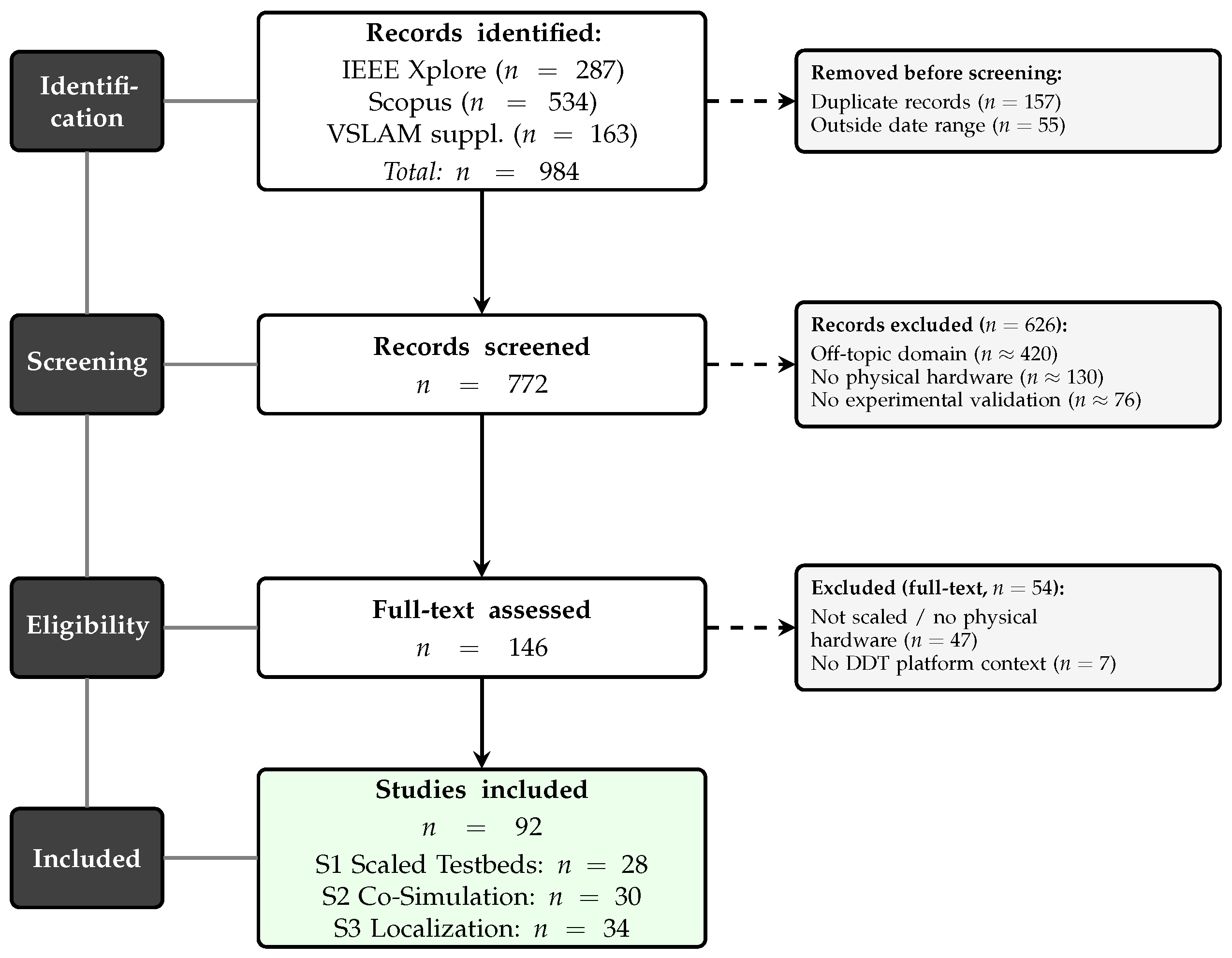
Figure 1 presents the PRISMA 2020 flow diagram summarising the record counts at each stage of the selection process.
The two databases together yielded 821 records in total (IEEE Xplore: n = 287 ; Scopus: n = 534 ). The supplementary VSLAM search contributed a further 163 records, resulting in 984 records identified across all searches. After removing 157 cross-database and intra-search duplicates identified by DOI matching and 55 records published before 2015, a total of 772 unique records within the 2015–2026 window were screened at the title and abstract level. Of these, 626 were excluded on the basis of the criteria above, with the principal reasons being off-topic domain, absence of physical hardware, and insufficient experimental validation. The remaining 146 records were assessed at full-text level, of which 54 were excluded, yielding a final corpus of 92 primary sources. These are distributed across the three topic clusters as follows: 28 on scaled testbeds, 30 on co-simulation architectures, and 34 on indoor localization methods. Characteristics of all 92 included primary studies are provided in Supplementary Table S1.
It should be noted that this review is scoped to the three defined topic clusters and does not claim exhaustive coverage of the broader Digital Twin or autonomous driving literature. Works addressing these topics tangentially (for example, purely algorithmic contributions without a hardware or testbed component) were excluded to maintain focus and to ensure that all included sources contribute directly to the comparative analyses in Section 4, Section 5 and Section 6.

4. Co-Simulation Architectures for Scaled Testbeds

Co-simulation frameworks for autonomous driving validation must satisfy a demanding combination of requirements: high-fidelity sensor modelling, deterministic real-time execution, and seamless interoperability between physical hardware and the virtual environment. The systematic search described in Section 3 identified a corpus of co-simulation studies spanning full-scale [21,22,23] and scaled [3,24,25] testbed deployments, as well as framework-oriented contributions [5,6,26]. This section synthesises these findings by reviewing the principal simulation platforms (Section 4.1), the role of ROS 2 as integration middleware (Section 4.2), synchronisation mechanisms (Section 4.3), and the selection rationale for the DDT system (Section 4.5).

4.1. Simulation Environments

Four open-source simulation platforms dominate the autonomous driving research landscape: AirSim, CARLA, Gazebo, and LGSVL. Each reflects different design priorities and presents distinct trade-offs with respect to rendering fidelity, physics accuracy, licensing, and real-time performance.
AirSim [27], developed by Microsoft Research and built on Unreal Engine, provides physically based rendering (PBR), modular sensor models, and synchronous and asynchronous control APIs for cars and multirotor vehicles. Its native ROS 2 bridge (airsim_ros_pkgs) maps simulation state variables directly to ROS 2 topics, enabling tight integration with external control and perception pipelines without additional middleware adaptation. AirSim supports both event-driven and clock-driven simulation modes, making it well-suited to real-time co-simulation scenarios where deterministic step execution is required. Its comparatively lightweight footprint on edge hardware (a property explicitly evaluated by [11]) and the absence of licensing costs make it particularly attractive for academic and educational deployments. The original Microsoft Research AirSim repository was archived in 2022 [11]; the community fork Colosseum maintains full API and ROS 2 bridge compatibility and is the recommended entry point for new deployments. In this work, the DDT co-simulation bridge (Section 7.1) uses AirSim v1.8.1 (Colosseum fork) running on Unreal Engine 5.4.4.
CARLA [28] (latest release at the time of writing: v0.9.15), also Unreal Engine-based, is the most widely adopted platform in ADAS research owing to its rich urban scenario library, procedural map generation tools, and active community. Its sensor suite, including LiDAR, RGB and depth cameras, GNSS, IMU, and radar, supports end-to-end perception benchmarking under photorealistic conditions. CARLA interfaces with ROS 2 via a community-maintained bridge and has recently been extended with SUMO integration for traffic flow co-simulation [11]. However, its resource requirements are substantial: full-resolution rendering on edge hardware, such as the NVIDIA Jetson AGX Orin, is constrained, and guaranteeing the low end-to-end latency required for real-time co-simulation is more challenging than with AirSim. CARLA has been used as the simulation backend in a number of HIL testbeds for autonomous driving research; Brogle et al. [5] established an FSAE-based HIL system around CARLA running on a Jetson TX1 and validated sensor output and vehicle dynamics against the physical platform, demonstrating that the simulation can operate effectively without hard real-time constraints. Similarly, the microAutoware framework [6] couples CARLA with an STM32-based embedded vehicle interface via ROS 2, enabling end-to-end HIL validation of both high- and low-level AV software layers.
Gazebo [29] (now Ignition Gazebo/Gz; latest named release at the time of writing: Gazebo Ionic) is natively integrated with ROS 2 and remains the standard simulation environment for mobile robot development. Its physics engine (ODE, Bullet, DART) provides accurate rigid-body dynamics and supports a broad range of sensor plugins. Gazebo’s rendering quality, based on the OGRE engine, is significantly lower than Unreal-based platforms, which limits its utility for camera-based perception tasks. It is, however, the preferred choice when physics fidelity and ROS 2 compatibility are prioritised over visual realism.
LGSVL (final release: SVL Simulator v2021.3, October 2021), built on Unity, offered high-fidelity rendering and an SVL Simulator Python 2021 API (v2021.3) supporting both synchronous and asynchronous operations. Active development was discontinued in 2022, after which community forks (AWSIM, SVL-compatible variants) have partially continued its legacy [11]. The reduced community support limits its suitability for new deployments.
Table 1 summarises the key characteristics of the four platforms with respect to the requirements of a scaled DDT testbed.

4.2. Middleware Integration: ROS 2 as the Co-Simulation Backbone

The Robot Operating System 2 (ROS 2) has established itself as the de facto middleware standard for autonomous driving research, combining a publish–subscribe communication model with the Data Distribution Service (DDS) for reliable, real-time data exchange [13]. In contrast to its predecessor, ROS 2 eliminates the single-point-of-failure master node, introduces Quality of Service (QoS) policies for fine-grained latency and reliability control, and provides native support for multi-robot and distributed deployments, all of which are directly relevant to co-simulation architectures where physical and virtual components communicate across a network boundary.
In a scaled DDT context, ROS 2 serves three distinct functions. First, it acts as the communication substrate between the physical vehicle (running localisation, control, and perception nodes on an on-board computer) and the simulation host. Second, it provides data synchronisation through timestamped message headers and system-wide clock alignment via the Network Time Protocol (NTP). Third, it functions as a modular integration layer that allows individual subsystems (such as the active localisation pipeline) to be replaced or extended without modifying other components.
The choice of DDS implementation has a measurable effect on communication latency in ROS 2 deployments, particularly when the co-simulation pipeline grows large [30]. Because most DDS implementations cap domain participation at 120 nodes, a DDT system combining localisation, perception, control, ground-truth logging, and simulation bridge nodes can exhaust a single domain, making different-domain communication necessary [30]. Paul et al. evaluated three vendor-specific implementations (Cyclone DDS, eProsima Fast-DDS, and RTI Connext DDS) across wired and wireless hardware under varying payload sizes and publisher frequencies: same-domain communication consistently outperformed different-domain operation, and eProsima Fast-DDS exhibited the largest latency penalty in different-domain wired scenarios; Cyclone DDS showed the most stable latency across payload sizes in wired different-domain configurations, while RTI Connext DDS is recommended when both same-domain and different-domain operation must coexist in one system [30]. An independent characterisation of ROS 2 QoS profiles for autonomous driving pipelines by Battilani et al. [11] confirmed that perception-critical data streams can be configured to achieve P95 end-to-end latencies well below 50 ms under realistic workloads. The microAutoware HIL testbed reported a mean message latency of 32.5 ms (max 52.7 ms) from the embedded vehicle interface to Autoware, further validating the feasibility of ROS 2-based HIL communication within the target budget [6].
Scenario formalisation is an important open challenge in co-simulation workflows. Current co-simulation setups require substantial manual effort to define and configure each test scenario [31]. Basciani et al. [31] proposed a meta-model-based visual editor that allows ADAS testers to design test scenarios through a graphical interface, which are then automatically executed in the BeamNG.tech simulator. This approach addresses the lack of a unifying modelling notation in co-simulation and reduces the burden of low-level scenario configuration.
The SmartData integration framework of Cantas and Tümer [12] provides a complementary approach to middleware integration by orchestrating heterogeneous autonomous driving simulation tools through a common data broker. Such integration layers reduce the bespoke adaptation work required when combining multiple simulation environments and physical hardware components.

4.3. Real-Time Synchronisation Mechanisms

Maintaining temporal coherence between the physical and virtual domains is the central technical challenge of any co-simulation framework. Two distinct synchronisation strategies are commonly employed: non-real-time (step-driven) and free-running.
In non-real-time (step-driven) co-simulation, the simulation advances as fast as the hardware allows, without enforcing a wall-clock constraint between steps. Brogle et al. [5] presented an HIL system built on CARLA that operates without hard real-time constraints, running at an average of 45 FPS, and demonstrated that this is sufficient for validating high-level autonomy software such as image processing and path planning. Time synchronisation in this mode relies on NTP; Brogle et al. measured a 35 ms inter-node clock offset with a remote NTP server and identified a local NTP server as the next improvement step. This non-real-time mode is well-suited to offline validation tasks where reproducibility and throughput are prioritised over wall-clock fidelity.
Free-running co-simulation, by contrast, allows both domains to advance independently, exchanging state updates at a fixed publication rate. Temporal misalignment is managed through timestamped message headers and a circular buffer that interpolates between consecutive frames [12]. This approach introduces a bounded measurement delay (typically one to two communication cycles) but maintains smooth visual feedback and closed-loop control at the required update rate. For DDT applications where the physical vehicle must perceive and respond to the displayed virtual scenario in real time, free-running co-simulation with a target latency of ≤50 ms is the appropriate operating mode.
In a master–slave architecture, the simulation environment acts as the authoritative time source, broadcasting synchronisation packets containing the current timestamp, reference vehicle state, and scenario metadata. The physical subsystem responds with sensor readings and control feedback. Late or out-of-order packets are interpolated or discarded according to the system latency threshold. For wired deployments, NTP provides adequate synchronisation for most DDT use cases; the Precision Time Protocol (PTP/IEEE 1588) is available as an alternative for applications requiring sub-millisecond jitter [5].
The Live Virtual Constructive (LVC) paradigm extends co-simulation beyond a single physical–virtual pair to encompass federations of live vehicles, virtual simulations, and constructive models in a common exercise space [32]. Scaled testbeds can participate in LVC exercises as the “live” component, enabling multi-domain safety and security validation scenarios that would be impractical to stage with full-scale vehicles [32].

4.4. Scaled Physical–Virtual Testbeds

Among existing scaled co-simulation platforms, AutoDRIVE [3] represents a particularly comprehensive open-source ecosystem. It integrates a scaled physical vehicle with a digital twin simulator, supporting hardware-in-the-loop testing interfaces alongside software-only operation. The testbed includes a surveillance camera (AutoDRIVE Eye) that estimates vehicle pose by detecting AprilTag markers mounted on the vehicle roof, an overhead localisation approach directly analogous to the one adopted in the DDT system described in Section 7. AutoDRIVE supports a range of autonomous driving use cases, including parking, intersection traversal, behavioural cloning, and smart-city V2X scenarios.
A complementary approach to scaled AV development is demonstrated by Coelho et al. [33], who assembled a 1:10 scale platform integrating a 2D LiDAR, monocular camera, and IMU on a commercial RC chassis running the open-source DonkeyCar framework on a Raspberry Pi 5. Rather than coupling the platform to a virtual environment, the authors focused on end-to-end deep learning control: a CNN-LSTM hybrid model achieved a validation loss of 0.059 %, outperforming linear CNN baselines (0.187 %) at the cost of a 5.8× longer training time, with all processing modules remaining below the 50 ms real-time latency target. The platform demonstrates that a minimal sensor stack and open-source tooling are sufficient for reproducible scaled AV research, but the absence of a digital twin interface limits its applicability to pure physical testing scenarios.
Several agent-based simulation approaches have been proposed for multi-vehicle scaled testbeds. A low-cost HIL agent-based simulation testbed [34] demonstrated that agent-based co-simulation can capture traffic flow dynamics relevant to connected vehicle research at reduced infrastructure cost. The scalability of such agent-based approaches to multi-vehicle DDT scenarios remains an open research question.

4.5. Comparative Analysis and Selection Rationale

Based on the review presented in Section 4.1 through Section 4.4, AirSim emerges as the most suitable simulation platform for the scaled DDT context addressed in this paper. The key factors are its native ROS 2 bridge, its demonstrated real-time performance on edge hardware, its MIT licence, and its explicit support for synchronous simulation modes. CARLA represents a compelling alternative for scenarios requiring urban environment fidelity or traffic agent diversity, and several HiL implementations have validated its suitability for non-real-time co-simulation [5,6]; however, its resource demands and the absence of a native ROS 2 bridge introduce additional integration complexity that is difficult to justify at the 1:14 scale. Gazebo is the preferred choice for purely robotics-oriented deployments where visual realism is secondary to physics accuracy and ROS 2 compatibility. LGSVL is no longer recommended for new deployments given the discontinuation of active development.
The middleware selection for the DDT system described in Section 7 is ROS 2 Humble on Ubuntu 22.04, providing long-term support compatibility with the ZED2 stereo camera SDK, the apriltag_ros package, and the airsim_ros_pkgs bridge. The free-running co-simulation mode with a ≤50 ms latency budget and NTP-based clock alignment is adopted as the target operating configuration, consistent with the latency budgets observed in comparable HiL deployments [5,6].

5. Indoor Localization Methods for Scaled Testbeds

Accurate, low-latency localization of the physical vehicle is the central technical requirement of any DDT system: the quality of the real–virtual synchronization loop is bounded above by the accuracy and update rate of the pose estimate [17]. This section reviews the three localization technologies identified by the systematic search as most relevant to scaled indoor testbeds: AprilTag-based optical tracking (Section 5.1), Visual Simultaneous Localization and Mapping (Section 5.2), and Ultra-Wideband radio positioning (Section 5.3). A fourth candidate technology, infrared marker-based systems, was identified by the search but is represented by only three records in the indexed literature; it is discussed briefly in Section 5.4 for completeness and excluded from the primary comparative evaluation. Camera calibration prerequisites for vision-based approaches are discussed in Section 5.5, followed by a multi-criteria comparative evaluation (Section 5.6).

5.1. Fiducial Marker-Based Localization: AprilTags

AprilTags [19] are square visual fiducial markers that encode a unique binary identifier within a high-contrast border, enabling robust 6-DOF pose estimation from a single camera image. Each tag family defines a set of valid codewords with a known minimum Hamming distance, providing resistance to false detections even under partial occlusion or motion blur [19]. A ceiling-mounted camera observing markers affixed to tracked objects provides a top-down absolute pose estimate that is drift-free by construction, a property not shared by odometry-based methods [18].
Kallwies et al. [35] conducted an extensive comparison of four freely available AprilTag detection libraries, including AprilTag 3 and ArUco, and found that sub-pixel edge refinement techniques can substantially improve localization accuracy at the cost of a modest increase in processing time. The study also demonstrates that the choice of detection library has a measurable impact on pose accuracy, with AprilTag 3 performing best in controlled indoor conditions.
Beyond single-marker setups, multi-marker approaches address the occlusion vulnerability of conventional AprilTag deployments. Braun et al. [36] introduced the Kabsch Marker Estimation Algorithm (KMEA), which uses all simultaneously visible ArUco markers (without requiring camera extrinsic parameters) to compute an optimal rigid-body transformation between detected and known marker positions. In standard controlled scenarios, KMEA achieved millimetric precision with a mean relative error below 1% of the workspace dimension; under occlusion-heavy conditions, it reduced error metrics by 86.9–92% compared to a single-marker baseline, demonstrating robust graceful degradation when markers are partially blocked [36]. Barros et al. [37] extended the concept to a multi-camera setup in which a five-sided ArUco marker cube affixed to the tracked robot is observed by 3–5 distributed cameras without requiring a top-down overhead perspective. Their system reduced root-mean-square position error (RMSE) from 13.45 cm to 3.6 cm (a 73% improvement) while halving the required number of cameras compared to a single-marker predecessor, and operates without IMU or odometry data from the robot [37].
The fusion of marker detection with probabilistic filters extends the applicability of AprilTag-based approaches to dynamic scenarios. Kayhani et al. [38] implemented an EKF that simultaneously fuses pose estimates from all currently visible AprilTag markers with IMU measurements for UAV indoor localisation in GPS-denied construction environments, achieving substantially improved accuracy compared to single-tag detection. Chen et al. [39] showed that fiducial markers can be incorporated directly as landmark nodes in a visual SLAM graph optimisation: adding ArUco marker reprojection constraints alongside natural ORB (Oriented FAST and Rotated BRIEF) keypoints yielded a superior trajectory accuracy compared to ORB-SLAM2 alone on low-texture indoor datasets, illustrating how marker-based and feature-based localisation are complementary rather than competing.
The primary limitation of AprilTag-based localization is its dependence on an unobstructed line of sight between the marker and the camera. Any occlusion results in a complete loss of the pose estimate rather than a graceful degradation. Accuracy is furthermore directly coupled to camera calibration quality: systematic errors in the intrinsic parameters propagate into the estimated pose and cannot be corrected downstream [35]. These characteristics make AprilTag well-suited as a primary localization method in structured indoor testbeds where the camera field of view can be guaranteed, and as a complementary absolute reference for drift correction in odometry-based systems [18].

5.2. Visual Simultaneous Localization and Mapping (VSLAM)

Visual Simultaneous Localization and Mapping (VSLAM) algorithms build a sparse or dense map of the environment while simultaneously estimating the camera pose within it [17,18]. Unlike marker-based methods, VSLAM requires no pre-installed infrastructure; the visual structure of the environment itself serves as the positional reference. This makes it attractive for scenarios where marker deployment is impractical or where the test environment changes frequently between sessions.
Representative open-source implementations include ORB-SLAM3, RTAB-Map, and OpenVSLAM, each offering different trade-offs between accuracy, map representation, and computational load. Merzlyakov and Macenski [40] benchmarked ORB-SLAM3, OpenVSLAM and RTABMap across indoor (EuRoC MAV, TUM RGB-D) and outdoor (KITTI) datasets. The study concluded that OpenVSLAM provided the best overall performance across sensor configurations and environments, while RTABMap showed the highest determinism. Notably, both VSLAM systems degraded significantly on the low-texture TUM RGB-D sequences, with RTABMap performing best in those conditions, underscoring the sensitivity of feature-based VSLAM to textureless surfaces [40]. Stereo visual-inertial odometry, which fuses image-based feature tracking with IMU measurements, extends monocular VSLAM by providing metric-scale estimates and improved robustness to fast rotational motion [18].
The challenge of homogeneous indoor surfaces was studied specifically by Ibragimov and Afanasyev [41], who compared monocular ORB-SLAM, monocular DPPTAM, stereo ZedFu, and RTAB-Map (RGB-D) on a UGV traversing an office corridor with uniformly painted walls and glass fences. Monocular approaches degraded significantly in the low-texture environment, while stereo inputs (ZedFu via a Stereolabs ZED camera) provided substantially more robust tracking under a homogeneous surface conditions, a finding directly relevant to scaled indoor testbeds with feature-poor floor or wall surfaces [41]. Kaveti et al. [42] addressed single-camera fragility by proposing a generic sparse VSLAM framework that represents an arbitrary multi-camera rig as a single imaging device via the generalised camera model and exploits cross-matched features in overlapping fields of view. The framework was evaluated on indoor datasets with narrow corridors, featureless spaces, and dynamic obstacles, achieving real-time execution; multi-camera configurations provided improved robustness compared to single-camera baselines in all challenging scenarios [42]. Chow et al. [43] introduced a task-driven benchmarking methodology for SLAM algorithms in dynamic ROS 2 environments, comparing RTAB-Map (visual SLAM) and SLAM Toolbox (2D LiDAR SLAM) across eight experiments with moving obstacles. Using goal completion rates and pose consistency as metrics, visual SLAM achieved greater precision, while 2D LiDAR SLAM achieved higher task success reliability, a complementary trade-off that motivates sensor-fused localisation architectures [43].
The principal limitation of VSLAM in indoor testbed applications is its sensitivity to textureless or low-feature surfaces. Uniform-coloured or repetitively patterned floor surfaces reduce the number of trackable visual features and can degrade localization quality significantly [17]. A further limitation is drift accumulation: VSLAM produces a pose in a locally consistent odometry frame rather than a globally referenced world frame. Loop closure detection can partially mitigate drift in larger environments, but in confined areas with repetitive surface patterns, loop closure opportunities are limited [40]. Practical deployments therefore benefit from periodic re-initialisation against a known absolute reference to bound drift accumulation, a requirement that motivates the ground truth strategies reviewed in Section 6.

5.3. Ultra-Wideband (UWB) Radio Positioning

Ultra-Wideband localization uses time-of-flight (ToF) or time-difference-of-arrival (TDOA) measurements between fixed anchor nodes and a mobile tag to estimate position by trilateration [17]. UWB operates over extremely wide frequency bands, which enables sub-nanosecond timing resolution and centimetre-level ranging accuracy even in environments with moderate multipath reflections [17,18].
Experimental studies confirm the practical accuracy achievable with current UWB hardware. Khoshrangbaf et al. [44] compared UWB against Wi-Fi and Bluetooth Low Energy (BLE) for mobile robot tracking in a 431 m 2 indoor environment using only four anchors. The average static positioning error of the UWB system remained below 13.1 cm across all test rooms, and the average dynamic tracking error was 28.9 cm, an improvement of 88% over BLE and 93% over Wi-Fi. The study demonstrates that even a minimal four-anchor configuration yields substantially higher accuracy than alternative radio technologies for mobile robot tracking.
Integrating UWB with complementary sensors improves robustness in non-line-of-sight (NLOS)-prone environments. Elsanhoury et al. [45] fused UWB ranging with IMU data using an EKF augmented with Rauch–Tung–Striebel (RTS) smoothing and multivariate regression offset compensation in an industrial laboratory (28 × 15 m2, six anchors, dense multipath). Using a ground-truth reference robot, the proposed UWB/IMU EKF-RTS method achieved a mean positioning accuracy of 4.7 cm and a 95th-percentile error of 9.6 cm, substantially outperforming plain EKF fusion. Ranjan et al. [46] systematically compared low-pass filter (LPF) integration with moving-average (MVG), Kalman (KF), and extended Kalman (EKF) estimators for UWB positioning on a TurtleBot platform. EKF + LPF achieved the lowest error across all trajectory types (RMSE 40.2 mm in X and 78.7 mm in Y for square paths) and reduced MAE by 3.4–6.2% compared to unfiltered variants [46].
Ma et al. [47] addressed signal-interference scenarios via genetic algorithm–optimised extreme learning machines (GA-ELM) that classify the presence of RF interference and compensate UWB ranging errors. Without interference, the compensated RMSE reached 14.5 cm (a 71.3% reduction); under active interference, 28.1 cm (a 64.4% reduction) [47]. Multi-robot cooperative UWB localisation, in which vehicles range to both fixed anchors and to each other, was studied by Xin et al. [48], who demonstrated a GPU-accelerated cooperative particle filter with Bayesian NLOS error mitigation achieving 3.2-fold latency speedup for three TurtleBot2 robots (11.9-fold for seven), with positioning accuracy surpassing EKF and PF baselines. Li et al. [49] demonstrated seamless indoor–outdoor UWB positioning for a low-cost UGV via tight coupling of Precise Point Positioning (PPP), Inertial Navigation System (INS), and UWB measurements. A two-step weighting strategy mitigated NLOS and multipath errors, achieving horizontal MAEs of 0.21 m and 0.19 m in the east and north directions during real-world indoor/outdoor transitions [49].
The main advantage of UWB over vision-based methods is its independence from lighting conditions and the visual appearance of the environment: the position estimate remains unaffected by changes in ambient illumination or surface texture [17]. Its primary disadvantages are the infrastructure overhead (a minimum of three non-collinear anchors must be installed at surveyed positions) and sensitivity to NLOS conditions caused by metallic objects or moving obstacles entering the ranging path [18]. Geometric Dilution of Precision (GDOP) further affects accuracy in regions where the anchor geometry is unfavourable, making anchor placement optimisation an important implementation consideration [17].

5.4. Infrared-Based Marker Systems

Infrared (IR) marker tracking uses active IR LED light sources mounted on the tracked object in combination with a camera equipped with an optical band-pass filter matched to the LED emission wavelength [17]. By restricting the camera’s spectral sensitivity to the narrow IR band, the approach achieves near-immunity to changes in visible ambient lighting, a significant advantage in environments with variable or challenging illumination conditions [17,18].
The systematic search described in Section 3 identified only three records explicitly addressing IR marker-based localization for robot or vehicle applications in constrained indoor environments. This limited representation in the indexed literature, compared to fiducial marker and UWB approaches, reflects the relatively niche adoption of active IR systems in mobile robotics research. The primary reported disadvantages are the need for custom hardware modifications, increased system complexity relative to passive marker approaches, and sensitivity to IR-reflective surfaces that can generate spurious detections [17]. These factors, combined with the sparse benchmarking literature, currently limit systematic performance comparisons for this approach.
A more mature class of IR-based ground truth technology is represented by commercial optical motion capture (MoCap) systems such as OptiTrack and Vicon. These systems use arrays of calibrated IR cameras surrounding the capture volume to track passive retroreflective markers at sub-millimetre accuracy (typically < 1 mm) and at update rates exceeding 200 Hz [17,18]. MoCap systems are regarded as the laboratory gold standard for ground truth in robotics and biomechanics. However, their adoption in scaled DDT testbeds is limited by three factors: (1) capital cost (entry-level multi-camera setups exceed €15,000, with research-grade installations reaching €50,000 or more); (2) fixed installation requirements that tie the system to a specific room geometry; and (3) the need for line-of-sight between cameras and markers, which can be disrupted by the vehicle body or overhead camera mounts. These constraints make MoCap impractical as a general-purpose ground truth solution for Learning Factory deployments, where portability and redeployability are design requirements. The PGTRS concept addresses this gap by targeting sub-centimetre spatial reference accuracy without fixed camera arrays or per-deployment calibration overhead.

5.5. Camera Calibration for Vision-Based Localization

Camera calibration determines the mathematical relationship between three-dimensional world coordinates and two-dimensional image coordinates for a specific camera–lens combination [50]. For vision-based localization methods such as AprilTag detection and VSLAM, the quality of calibration directly determines the achievable positional accuracy: an uncalibrated camera introduces systematic errors in pose estimation that no downstream algorithm can correct [35].
The standard model for camera projection is the pinhole model, which describes the projection of a 3D world point X = ( X , Y , Z ) onto image coordinates ( u , v ) via the camera intrinsic matrix:
K = f x 0 c x 0 f y c y 0 0 1
where f x , f y are the focal lengths in pixels and ( c x , c y ) is the principal point. Real lenses deviate from this ideal model through radial and tangential distortion, described by the Brown–Conrady coefficients [50].
For wide-angle lenses with a horizontal field of view exceeding approximately 90°, the polynomial expansion of the Brown–Conrady model becomes numerically unstable and fails to capture the full distortion magnitude [20]. In this regime, the Kannala–Brandt equidistant model is preferred, describing the projection using a symmetric polynomial in the angle of incidence θ  [20]:
r ( θ ) = k 1 θ + k 2 θ 3 + k 3 θ 5 + k 4 θ 7
Calibration quality is quantified by the mean reprojection error: the mean Euclidean distance in pixels between detected checkerboard corner coordinates and their model-predicted reprojections. A value below 0.5 pixels is generally considered high-quality; values above 1.0 pixel indicate an insufficient distortion model or poor calibration images [50]. Zhang’s method [50] using a planar checkerboard target is the standard approach implemented in tools such as the ROS 2 camera_calibration package and the Kalibr toolbox [20].

5.6. Comparative Evaluation of Localization Methods

Table 2 summarises the key performance characteristics of the three primary localization methods, with IR markers included for reference. Accuracy and latency values are drawn from the representative literature reviewed in Section 5.1, Section 5.2, Section 5.3 and Section 5.4. Because these values originate from heterogeneous study environments with differing hardware, scene complexity, and evaluation protocols, they must not be interpreted as direct performance comparisons under equivalent conditions. The table is intended to characterise the typical operating regime of each modality, not to rank methods on a common performance scale.
No single method dominates across all criteria. AprilTag provides drift-free absolute positioning with low infrastructure overhead, but requires an unobstructed line of sight and is sensitive to camera calibration quality [35]. VSLAM offers the greatest deployment flexibility, requiring no external infrastructure, but accumulates drift over time and degrades on low-texture surfaces [17,40]. UWB is the most robust to visual and environmental conditions but requires a fixed anchor infrastructure and careful geometric placement [17,18]. IR marker systems provide illumination robustness at low cost but suffer from sparse benchmarking coverage and hardware complexity [17].
Multi-marker and multi-camera extensions substantially improve the occlusion tolerance of AprilTag approaches [36,37], while filtering augmentations (RTS smoothing, EKF+LPF) bring UWB accuracy below 5 cm in favourable configurations [45,46]. Nevertheless, no single method satisfies all requirements simultaneously. The complementary trade-off profiles of these methods motivate multi-method localisation architectures in which absolute marker-based fixes are combined with odometry-based or UWB-based estimates for improved robustness, an integration strategy discussed further in the context of the PGTRS proposal in Section 6 and the case study in Section 7.

6. Ground Truth Strategies for Indoor Localization Benchmarking

Meaningful comparison of localization methods requires a common, reliable spatial reference against which pose estimates can be evaluated. Without it, accuracy figures from different studies are expressed relative to different, and often incompatible, measurement baselines, making cross-study comparison uninformative. This section surveys the ground truth strategies identified by the systematic search (Section 3), identifies their limitations in the context of scaled indoor testbeds, and proposes the Programmable Ground Truth Reference System (PGTRS) as a novel approach that leverages the LED floor infrastructure of the DDT testbed to provide a reproducible, reconfigurable, and infrastructure-free spatial reference.

6.1. Conventional Ground Truth Approaches

Four classes of conventional ground truth are commonly employed in indoor localization research, each with characteristic trade-offs in accuracy, cost, and reconfigurability.
Optical motion capture systems (MoCap), such as OptiTrack and Vicon, use dense arrays of calibrated infrared cameras to track passive retro-reflective markers attached to the tracked object, achieving millimetre-level accuracy at update rates of 100 Hz or higher. This infrastructure-based approach is distinct from the active IR LED marker localization method discussed in Section 5.4: MoCap acts as an external reference instrument, not as an on-board localization method. Almassri et al. [51] used the OptiTrack motion capture system (MCS) as the reference in an evaluation of UWB/IMU data fusion, demonstrating that artificial neural network (ANN) based fusion can maintain accuracy close to the MCS level with a correlation coefficient exceeding 99%. However, MoCap systems impose significant infrastructure constraints: cameras must be installed at calibrated positions encircling the entire measurement volume, and the system is sensitive to marker occlusion and specular reflections from the floor surface. For a scaled indoor testbed of the size considered in this work, the installation of a full-perimeter MoCap array introduces costs that can exceed the total vehicle and computing budget and significantly complicates the learning-factory replication scenario.
Physical floor markings (painted grids, adhesive tape crosshairs, or laminated checkerboard sheets) provide static, low-cost reference points. Their chief limitation is the manual placement process: measurement uncertainty in marker position (typically ±2–5 mm for consumer tape measures) propagates directly into the ground truth accuracy, and any relayout of reference patterns requires physical labour and introduces new placement uncertainty. Such methods cannot be automated or reproducibly reconfigured without remeasurement.
Total station and laser tracker systems provide sub-millimetre reference positions through active optical distance and angle measurement. While suitable for one-time layout surveying, they are not a practical real-time ground truth provider for dynamic experiments: the measurement is a discrete, manually triggered operation rather than a continuous pose stream.
Infrastructure-based positioning as ground truth. Several works in the S3 corpus used one localization method as reference for evaluating another. The UTIL dataset [52] provides a representative example: Zhao et al. [52] collected UWB time-difference-of-arrival (TDOA) measurements using Decawave DWM1000 modules on a custom quadrotor over approximately 150 min of real-world flights under four-anchor constellations. Millimetre-accurate ground truth was obtained by fusing optical flow, time-of-flight laser altitude, and InEKF state estimation; crucially, this was not from an independent external reference but from an on-board sensor fusion that relies on the same low-level sensor primitives being benchmarked. This circular dependency limits the achievable ground truth quality, particularly under NLOS or low-light conditions.
Trekel et al. [53] addressed the multi-room ground truth problem by densely covering every room ceiling with fiducial ArUco markers and equipping the test robot with an upward-facing camera. The marker-based pose estimation provides a single global coordinate frame across multiple connected rooms without line-of-sight requirements between rooms. Their server-based benchmark evaluates long-term localisation algorithms under both short-term dynamics (moving people and objects) and long-term scene changes (rearranged furniture), covering a realistic office environment with 2D LiDAR, RGB-D cameras, and wheel odometry. This ceiling-marker approach is infrastructure-intensive (marker printing, ceiling mounting, and photogrammetric registration are required in every room) but produces a reproducible and objective ground truth over large multi-room areas.

6.2. The Programmable Ground Truth Reference System (PGTRS)

The systematic review in Section 5.1, Section 5.2 and Section 5.3 reveals that no published approach provides a ground truth method that is simultaneously: (i) accurate to within 1 cm in a 5 m × 5 m area, (ii) software-reconfigurable without physical intervention, (iii) applicable to all three major indoor localization modalities, and (iv) compatible with the budget constraints of a university-scale Learning Factory testbed. This gap motivates the following novel contribution.
Definition 2
(Programmable Ground Truth Reference System). A Programmable Ground Truth Reference System (PGTRS) is a digitally rendered spatial reference displayed on a programmable LED floor panel. It provides a set of precisely known two-dimensional positions and trajectories that serve as a spatial reference for benchmarking localization methods, with sub-pixel coordinate precision defined within the display’s native coordinate frame.
In the DDT testbed described in this work, the LED floor panel measures 5 m × 5 m and functions simultaneously as the physical driving surface for the 1:14 scale vehicle and as a programmable display. A fixed world coordinate frame  W is defined with its origin at the geometric centre of the floor, the x-axis pointing along the floor’s long axis, and the z-axis pointing upward. The physical correspondence between W and the metric dimensions of the floor is established once during system setup by measuring the four corner positions with a laser distance meter. This one-time registration procedure creates a globally consistent coordinate frame into which all three localization pipelines (AprilTag, VSLAM, and UWB) are configured to report.
Because the LED floor operates as a high-resolution programmable display, the coordinates of any rendered reference element (a grid point, a line segment, or a trajectory arc) are known exactly within the display’s native coordinate system, with sub-pixel precision. This eliminates the principal source of uncertainty in physical floor marking: the operator placement error. Any spatial reference pattern can be stored as a configuration file and rendered identically on any occasion, providing full experimental reproducibility without additional measurement. The PGTRS does not require any additional infrastructure beyond the LED floor already present in the testbed; it adds no cost and no setup overhead to experiments that are already using the floor as a co-simulation display.

6.3. Three-Stage Benchmarking Protocol

The PGTRS supports a structured three-stage evaluation protocol of increasing dynamic complexity. The sequential design allows each localization method to be validated against the same reference under identical conditions, with one method active at a time to avoid mutual interference.
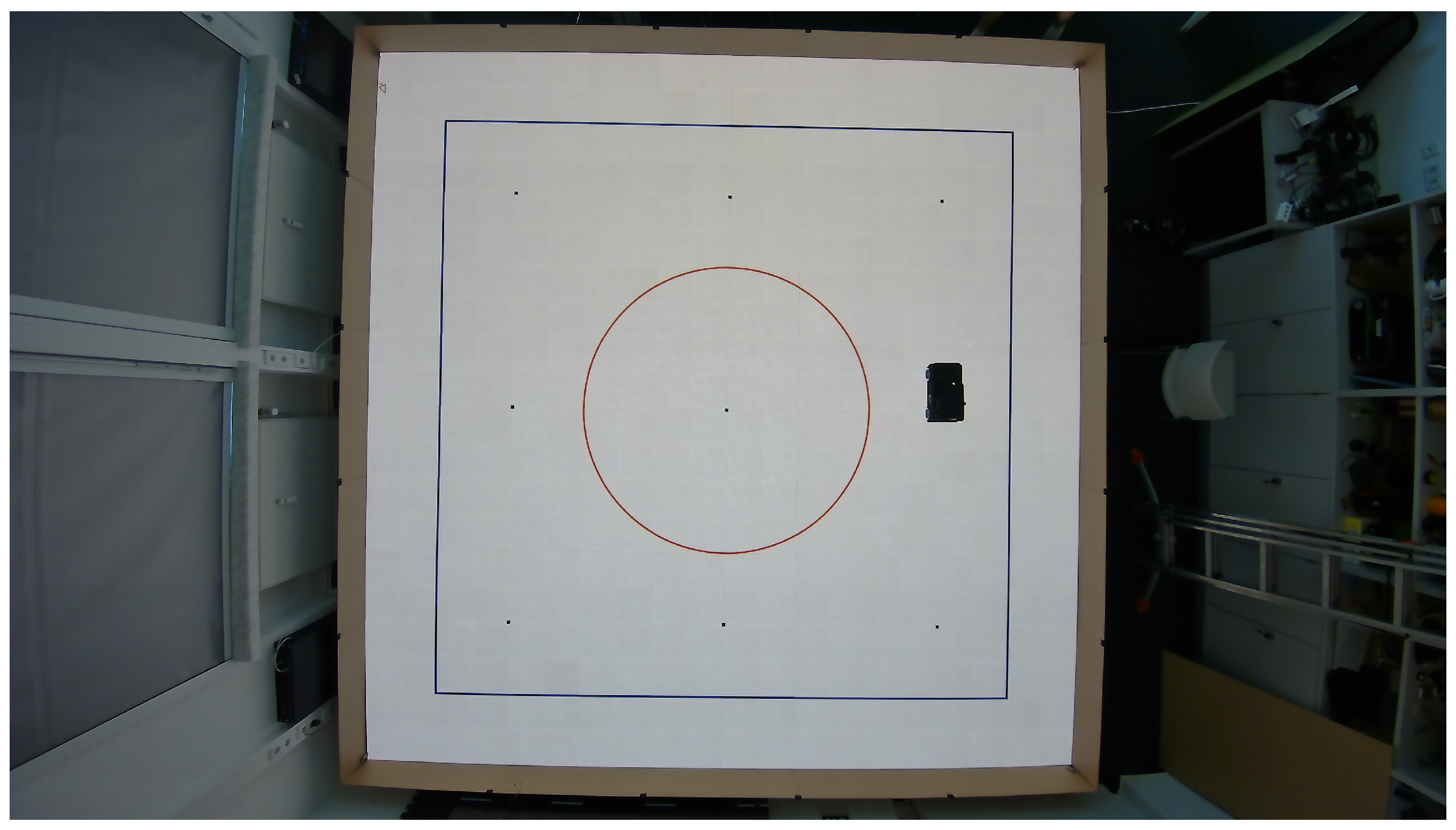
Stage 1: Static Grid Accuracy: The PGTRS renders a 3 × 3 grid of labelled reference points spaced 1.25 m apart, covering the full 5 m × 5 m test area. The vehicle is manually positioned with its reference point aligned to each grid position in sequence; all active localization topics are logged for 30 s per point at the method’s native update rate. The nine-point sequence is repeated three times per session across three separate days to capture session-to-session variability arising from changes in ambient lighting, system warm-up time, and minor repositioning differences.
Stage 2: Repositioning Repeatability: The vehicle is placed on the PGTRS coordinate origin, removed entirely from the floor, and replaced. This trial is repeated n times per localization method under constant environmental conditions. The resulting spread of position estimates isolates the repeatability of the physical placement procedure and the localization system’s initialization behaviour from the steady-state accuracy measured in Stage 1.
Stage 3: Dynamic Trajectory Accuracy: The PGTRS renders two reference trajectories: a 4 m × 4 m square and a circle with a 1.5 m radius. Both trajectories are executed autonomously by a pre-defined drive script rather than by a human operator, eliminating operator-induced variability as a confound. The square trajectory is executed as a sequence of straight segments at a fixed speed with fixed-duration turn commands at each corner. The circular trajectory is executed at a fixed forward speed with a constant steering angle calibrated to produce the target radius, yielding a geometrically consistent path on each repetition. Each trajectory is executed n times per localization method under identical lighting and floor display conditions.
The evaluation metrics across all three stages are: RMSE, mean absolute error (MAE), 95th-percentile positional error (P95), localization latency (measured via a hardware-synchronised LED trigger signal), outlier rate (fraction of estimates exceeding 5 cm), and computational load on the Jetson AGX Orin (mean CPU/GPU utilisation over 120 s static sessions). These six criteria correspond directly to the system requirements identified in Section 4.5: a maximum localization error of ±1 cm and a maximum end-to-end latency of 50 ms are the primary acceptance thresholds.
The protocol is designed to complement existing benchmarking frameworks such as that of Trekel et al. [53], which addresses long-term scene change robustness, by providing a high-repeatability reference for controlled, short-duration comparative evaluation of heterogeneous localization modalities within a single testbed.

7. A Representative Digital Driving Twin: Design and Architecture

This section describes a concrete DDT implementation that brings together the co-simulation platform (Section 4), the localization methods (Section 5), and the PGTRS benchmarking protocol (Section 6) in a single 1:14 scale testbed. The goal is to show how the reviewed components fit together in practice and to highlight the engineering decisions that future builders of similar systems will face.

7.1. System Architecture Overview

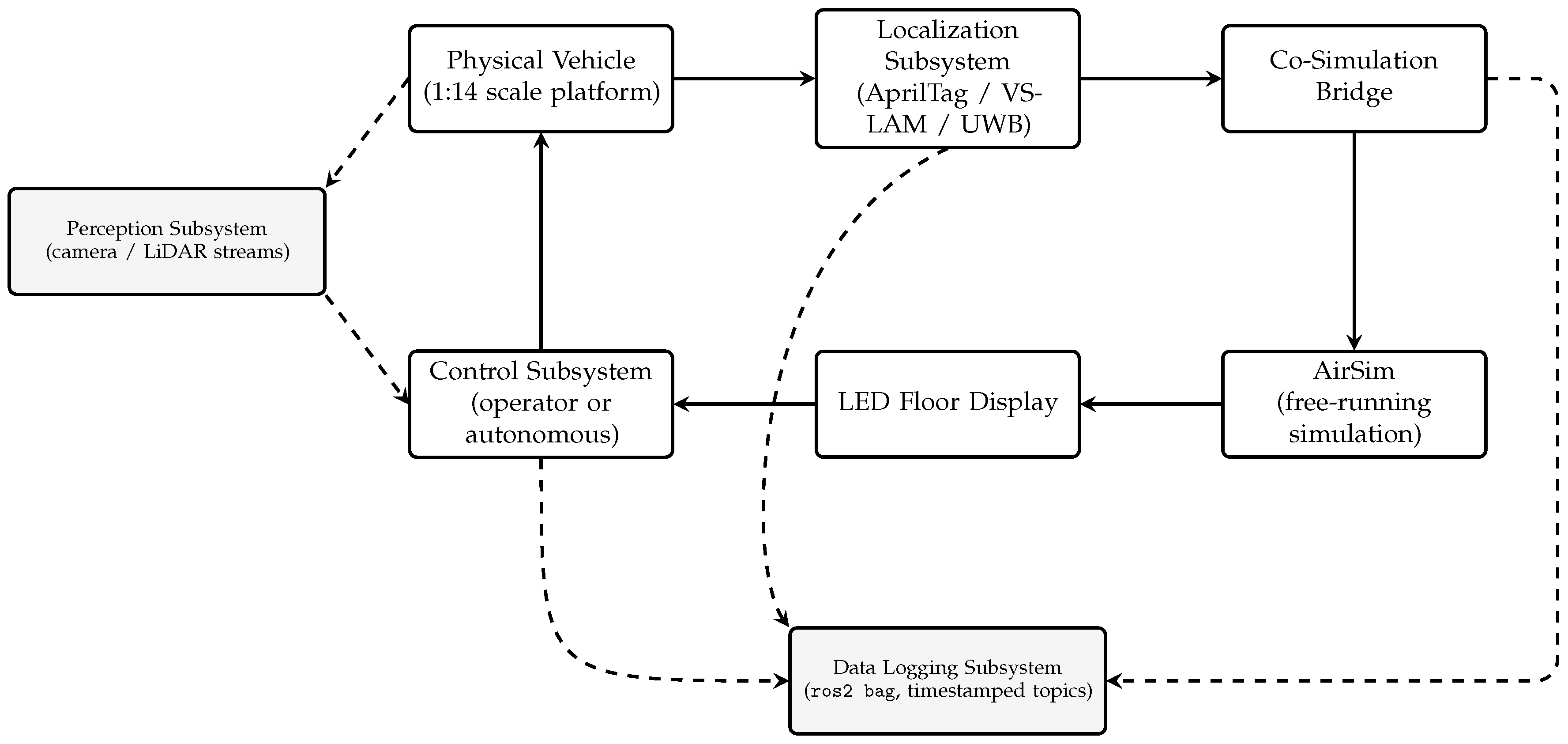
The DDT is organised into five functional subsystems, each implemented as a set of ROS 2 nodes that communicate via a common topic namespace. The modular design ensures that individual subsystems, most notably the localization pipeline, can be replaced or extended without modifying other components.
The localization subsystem runs the active pose estimation pipeline (AprilTag, VSLAM, or UWB) and publishes a unified /vehicle/pose topic in the world frame  W . The perception subsystem processes on-board camera and LiDAR streams for downstream object detection and scene understanding. The control subsystem consumes the current pose and a desired trajectory to produce actuator commands forwarded to the vehicle firmware via a low-latency serial bridge. The co-simulation bridge forwards the vehicle pose to the AirSim instance, receives the current simulation frame, and relays it to the LED floor display controller. This bridge implements the free-running co-simulation mode described in Section 4.3: the physical and virtual domains advance independently at their respective rates, exchanging state at a target cycle time of ≤50 ms. The data logging subsystem records all ROS 2 topics to ros2 bag files with hardware-timestamped message headers for post-hoc analysis.
The overall data flow forms a closed augmented-reality loop (Figure 2): the localization subsystem estimates vehicle pose → the co-simulation bridge updates the AirSim virtual vehicle → AirSim returns the simulated top-down view → the LED floor renders the virtual road network → the human operator or autonomous controller responds to the displayed scenario and steers the physical vehicle.

7.2. Hardware Platform

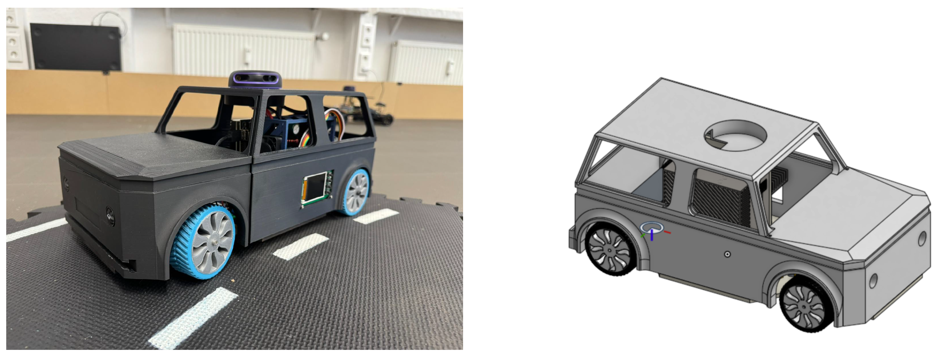
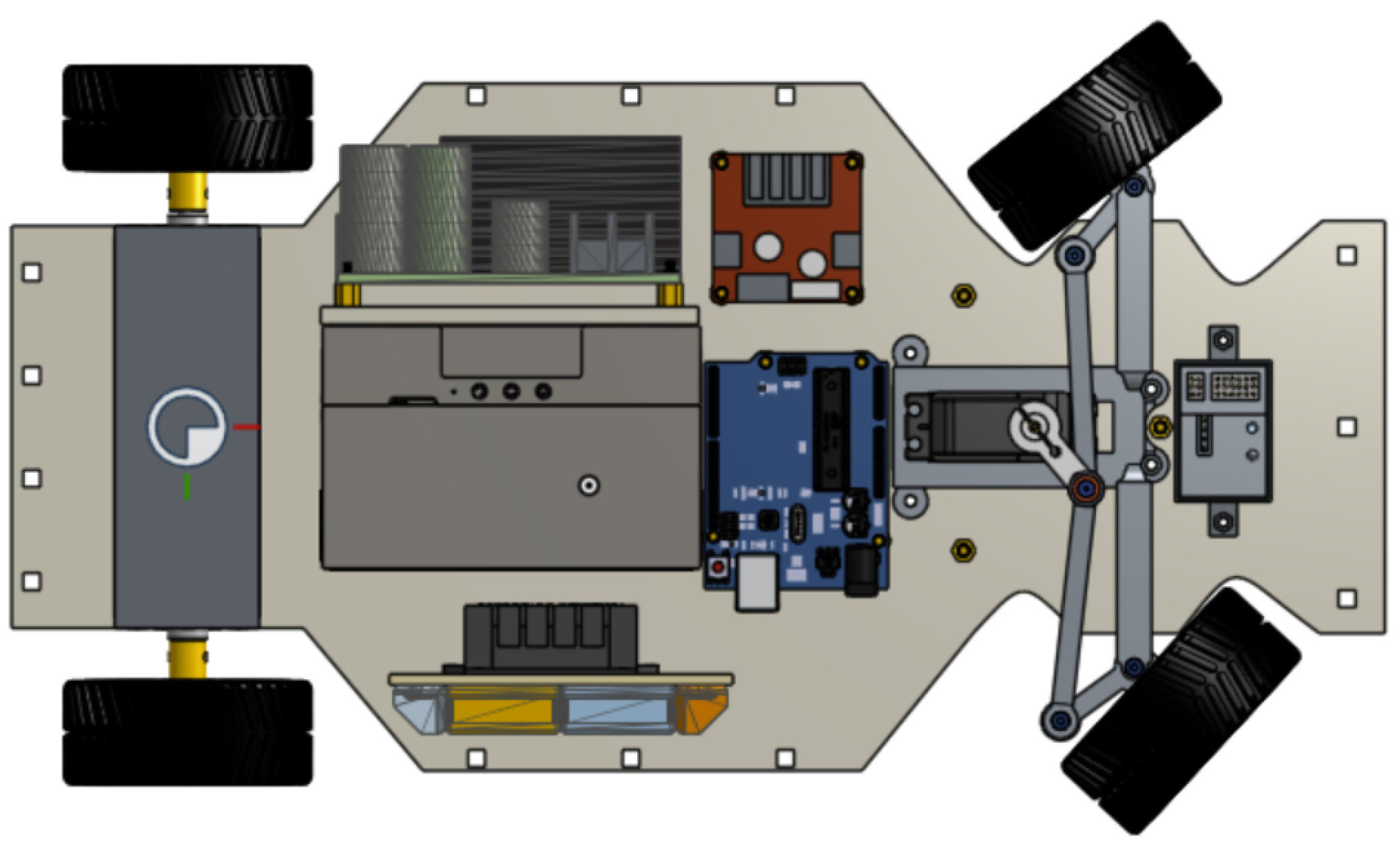
The scaled vehicle is a purpose-built 1:14 scale platform designed and fabricated in-house. The chassis base plate was cut from 5 mm MDF sheet using a laser cutter; all sensor and component mounts were designed in CAD and 3D-printed (PLA), with the exception of standard commercial spacers. Drive motors, actuators, and electronics were sourced as off-the-shelf components and integrated on the custom chassis. The on-board compute, sensing, and actuation components are summarised in Table 3.
The kinematic geometry and sensor placement of the vehicle platform are characterised in Table 4 and Table 5, following the methodology of O’Kelly et al. [54] and Malfi et al. [55]. All sensor positions are expressed in the vehicle body frame  B , whose origin is located at the rear axle on the underside of the 5 mm MDF chassis plate, with the x-axis pointing forward, the y-axis pointing to the left, and the z-axis pointing upward. The rear-axle reference point is marked in the CAD model (Figure 3) and is used as the common registration origin for all on-board sensors.
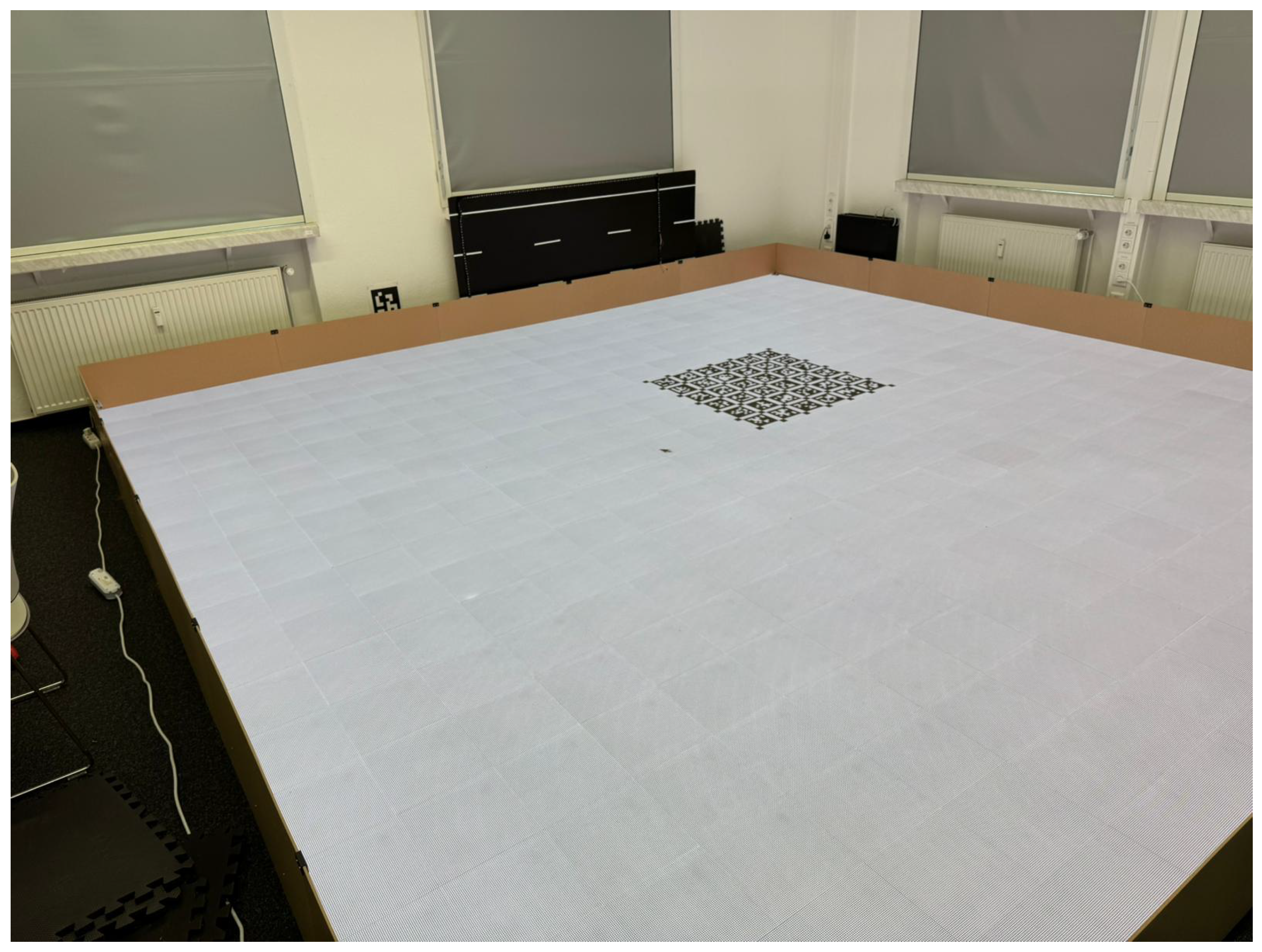
The LED floor panel (5 m × 5 m, comprising 20 × 20 modules of 64 × 64 pixels each, total resolution 1280 × 1280 pixels, pixel pitch ≈ 3.9 mm; Figure 4) is treated as shared laboratory infrastructure. An ELP IMX415 wide-angle (120°) 4K camera is mounted approximately 3.6 m above the floor surface pointing vertically downward, providing an overhead view sufficient to detect an AprilTag marker anywhere within the test area. Four UWB anchor nodes are fixed at surveyed positions at the corners of the testbed; their positions in W are measured once with a laser distance meter during system setup and stored in a static configuration file.
The LED floor panel is enclosed by a purpose-built wooden surround whose walls extend to a height above the RPLIDAR A1 scanning plane (approximately 30 cm above floor level). This enclosure serves three functions. First, it acts as a sensor containment boundary: the LiDAR’s 360° scan is geometrically limited to the 5 m × 5 m test area, excluding external environmental features such as chairs, radiators, and building structure from the point cloud and thereby eliminating a significant source of SLAM drift in open-plan laboratories. Second, it enforces a hard physical boundary for the coordinate frame  W , reinforcing the spatial registration established by the UWB anchors and the PGTRS reference grid. Third, the inner walls provide a mounting surface for optical markers and structured visual features: attaching visually distinctive or photogrammetrically calibrated markers to the enclosure walls would extend the observable landmark set for VSLAM and for the vehicle’s onboard forward-facing camera (Figure 5 Left), offering a low-cost path to improving VSLAM robustness within the bounded testbed environment.

7.3. Software Stack and ROS 2 Integration

All on-board processing runs on ROS 2 Humble (LTS) on Ubuntu 22.04. This combination ensures long-term support compatibility with the ZED SDK (via zed-ros2-wrapper), the apriltag_ros detection node, and the airsim_ros_pkgs co-simulation bridge. Cyclone DDS is selected as the DDS middleware following the recommendation of Paul et al. [30] for systems that require stable latency across varying payload sizes in wired same-domain configurations.
The three localization pipelines described in Section 5 are each implemented as a separate ROS 2 node graph publishing on a common interface topic /localization/<method>/pose. A lightweight pose selector node subscribes to all three topics and forwards the active method’s output to /vehicle/pose; switching between methods requires only a ROS 2 parameter update with no other code change. Clock alignment across the Jetson AGX Orin, the host PC running AirSim, and the UWB anchor infrastructure is provided by NTP; the 35 ms inter-node offset measured by Brogle et al. [5] under a remote NTP server is the expected upper bound, with a local Stratum-1 NTP server reducing this to approximately 1–5 ms in practice.
The AirSim simulation is configured in free-running mode with the vehicle kinematics driven externally from the ROS 2 control topic, consistent with the DDT operating mode identified in Section 4.5. The simulation renders a top-down orthographic projection of the active scenario onto a virtual canvas whose aspect ratio and pixel resolution match the 5 m × 5 m LED floor. This projection is transmitted via a low-latency socket to the LED floor controller, which updates the display within a target budget of 20 ms, leaving 30 ms for the localization and control loop within the overall target 50 ms co-simulation cycle.

7.4. PGTRS Integration in the DDT Pipeline

The PGTRS (Section 6.2) is deeply integrated into the DDT workflow. During normal co-simulation operation, the LED floor displays the AirSim simulation output. For localization benchmarking, a PGTRS mode is activated in which the AirSim output is replaced by the selected spatial reference pattern (static grid or dynamic trajectory). The switch between operating modes requires only a reconfiguration of the LED floor controller input source; the vehicle, sensors, and ROS 2 graph remain unchanged.
At startup, the VSLAM pipeline requires an initial alignment to the world frame W . The vehicle is placed at the PGTRS coordinate origin; a ROS 2 service call then records the current VSLAM odometry position as the frame offset, aligning the VSLAM frame to W . AprilTag and UWB pipelines do not require this initialisation step: AprilTag pose is computed in the camera frame and converted to W via a static transform calibrated during system setup, while UWB positions are computed directly in the anchor coordinate frame, which is registered to W at installation time.
This design ensures that all three localization methods publish in the same world frame at all times, enabling direct numerical comparison against the PGTRS reference without any post-hoc coordinate transform. The PGTRS thus provides not only a spatial reference but also a common coordinate frame enforcer, a function that is often neglected in multi-method localization studies, where each method reports in its own local frame. Figure 6 shows an example PGTRS pattern as captured by the overhead camera.

7.5. Educational and Research Applications

The DDT testbed is designed explicitly for the Learning Factory paradigm of Abele et al. [16], in which industry-relevant processes are replicated in an academic environment to create authentic experiential learning. In this context, the testbed enables structured laboratory exercises that cover the full autonomous driving development cycle: hardware assembly and calibration, localization pipeline configuration, co-simulation setup, performance benchmarking using the PGTRS protocol, and data analysis.
The total cost of approximately €6576 per testbed unit (excluding the LED floor, which is shared infrastructure) is comparable to the material cost of a well-equipped mechatronics project at a university engineering department. Similar cost-accessible scaled testbeds have been reported in the literature [3,13], but none combines a programmable LED floor with a formally defined ground truth benchmarking protocol in a single integrated system.
The modular ROS 2 architecture supports research extensions beyond the base configuration. Individual localization nodes, perception pipelines, and co-simulation bridges can be replaced or augmented without modifying the common interface layer. This makes the testbed suitable for student-driven research projects ranging from SLAM algorithm comparison to multi-agent coordination, while the PGTRS provides a reproducible baseline for inter-study comparison.

8. Discussion

8.1. Research Gaps and Open Challenges

The systematic review of 92 records across co-simulation architectures, indoor localization methods, and ground truth strategies reveals several consistent gaps in the existing literature.
Absence of standardised benchmarking protocols for scaled DDT localization. The S3 corpus confirms that localization accuracy figures are heterogeneous across studies: different methods, different environments, different reference systems, and different metric definitions make cross-study comparison almost meaningless. The UTIL dataset [52] is a notable exception in the UWB domain, but no equivalent publicly available benchmark exists for AprilTag or VSLAM in a scaled-vehicle indoor testbed context. The root cause is technical: different testbeds operate at different scales, arena sizes, and sensor configurations, meaning accuracy figures from one environment cannot be transferred to another. Without a shared physical reference device deployable across laboratories, a principled cross-study comparison has no foundation. The PGTRS protocol proposed in Section 6.3 directly addresses this gap by providing a reproducible, infrastructure-agnostic common reference applicable to all three modalities.
Sensor fusion across modalities is underexplored for scaled testbeds. Most reviewed works evaluated a single localization modality in isolation. A small number of studies (e.g., [45,46]) combined two technologies, but exclusively in the UWB+IMU domain. No study in the S3 corpus evaluated the complementary fusion of AprilTag absolute references with VSLAM relative odometry in a scaled indoor testbed, despite this combination being a logical match: AprilTag provides drift-free global position fixes while VSLAM provides smooth high-frequency relative motion, and their error sources are largely orthogonal. The underlying obstacle is tight time synchronisation: AprilTag detection and VSLAM odometry run on separate software stacks at different update rates, and the extrinsic calibration between their sensor frames must remain stable across sessions, a condition that is difficult to guarantee on constrained-edge hardware.
LED floor-specific localization challenges are unstudied. The LED floor introduces a unique artefact: when displaying uniform-colour road markings or solid areas, it creates featureless visual regions directly below the vehicle. For VSLAM systems relying on floor texture, this is a direct localization threat that has no analogue in conventional indoor testbeds. No existing study has investigated VSLAM performance on a programmable LED surface, making this an open problem for which the PGTRS testbed is uniquely positioned to contribute data. The gap arises from the novelty of programmable-floor testbeds: the dynamic visual content of the LED surface has no analogue in conventional indoor environments, so no prior VSLAM evaluation methodology accounts for it.
A countermeasure unique to programmable-floor testbeds is artificial feature injection: a low-contrast texture sublayer rendered on the LED surface alongside the primary scenario content provides consistent visual keypoints for SLAM front-ends without modifying the semantic content of the driving scene. Three pattern families are candidates, each with a different trade-off between keypoint richness and ADAS interference:
  • Voronoi grids. A randomised Voronoi diagram rendered at low contrast generates a large number of cell-boundary corners, which are the primary targets of ORB and FAST feature detectors. Irregular cell spacing prevents systematic repetition that CNN-based lane and object detectors could misinterpret as road markings, keeping the injected pattern below their saliency threshold.
  • Sparse fiducial sublayer. Small-scale AprilTags rendered at a resolution detectable by the overhead 4K camera but below the angular resolution of the vehicle’s forward camera provide absolute-scale anchors within the SLAM map, enabling periodic drift correction without modifying the scenario display.
  • High-frequency noise textures. Patterns whose dominant spatial frequency lies above the pass-band of vehicle-mounted cameras—for example, Perlin noise at a cell size smaller than two pixels at the camera’s operating distance—are perceptually invisible to the ADAS stack while remaining detectable by close-range VSLAM systems.
The governing design constraint is that injected features must be rendered at a contrast level and spatial frequency that keeps them below the saliency threshold of object and lane detectors, while remaining above the minimum gradient required for reliable keypoint extraction by the SLAM front-end. This threshold can be tuned per-scenario: a static parking scene tolerates higher injection density than an active lane-change manoeuvre with prominent road markings. The ability to switch the floor dynamically between a high-texture localization mode and a scenario display mode has not been demonstrated in any reviewed work and represents a unique capability of the PGTRS architecture relative to static ground truth systems.
Complementary to floor-based feature injection, the physical enclosure surrounding the LED panel (Section 7.2) offers a second enrichment surface: attaching photogrammetrically calibrated optical markers to the inner enclosure walls would extend the observable landmark set for both VSLAM and the vehicle’s onboard forward camera. Because the enclosure walls are fixed relative to W and visible from most positions within the test area, wall-mounted markers could provide absolute position anchors that suppress drift accumulation without requiring infrastructure changes beyond the testbed boundary.
Scalability of PGTRS to larger environments: The PGTRS as defined in Section 6.2 is tied to the LED floor form factor. For testbeds beyond the 5 m × 5 m footprint studied here, projector-based or large-format display alternatives would be needed. The sub-pixel precision guarantee depends on the display’s native resolution; scaling to larger areas at fixed pixel density increases cost non-linearly. This represents a boundary condition on the PGTRS concept.
Multi-vehicle localization is largely absent from the scaled testbed literature. Most reviewed scaled testbeds operated with a single vehicle. Multi-vehicle extensions introduce mutual occlusion (for vision-based methods) and ranging interference (for UWB). The cooperative UWB localization approach of Xin et al. [48] demonstrated a viable multi-robot ranging architecture, but was not evaluated in a co-simulation context. Combining multi-agent UWB ranging with a shared PGTRS coordinate frame is a natural next step.
PGTRS-enabled research directions: The PGTRS platform opens several specific experimental avenues that are not possible with static ground truth systems. First, the three-stage benchmarking protocol (Section 6.3) enables the first controlled cross-method accuracy comparison of AprilTag, VSLAM, and UWB under identical arena conditions and against a common spatial reference, directly resolving the heterogeneity problem identified above. Second, the PGTRS coordinate frame provides a natural drift-correction anchor for AprilTag+VSLAM fusion: AprilTag detections in the PGTRS grid can serve as periodic absolute position fixes that reset the VSLAM odometry integrator, combining the high update rate of VSLAM with the drift-free absolute accuracy of fiducial detection. Third, the artificial feature injection capability described above allows a systematic study of how LED surface texture density affects VSLAM keypoint extraction, yielding design guidelines for the optimal injection pattern as a function of the displayed driving scenario.

8.2. Design Guidelines for Scaled DDT Deployment

The following guidelines are distilled from the synthesis of reviewed literature and the DDT case study presented in Section 7. They are intended as decision support for practitioners building new scaled testbeds.
Localisation selection: use AprilTag as primary, UWB as reference. AprilTag provides drift-free global positioning with low infrastructure overhead and is the most directly verified approach for overhead-camera scaled testbed deployments [35,36,37]. UWB serves as a complementary positioning reference that is immune to visual occlusion [44,45]. VSLAM is appropriate when the floor surface provides sufficient texture and when a prior map of the environment is maintained.
Latency budget allocation: The 50 ms end-to-end co-simulation budget identified in Section 4.5 should be distributed as follows based on the reviewed literature: ≤20 ms for image capture and pose estimation (achievable with AprilTag at 30+ FPS [35]), ≤10 ms for ROS 2 DDS message forwarding [30], ≤20 ms for AirSim frame rendering and LED floor update. Any component exceeding its budget requires profiling and optimisation before system integration.
Calibration quality gates: Camera calibration reprojection error must remain below 0.5 pixels [50]; calibrations above 1.0 pixel indicate model mismatch or poor calibration images and will corrupt downstream pose estimates in proportion to the error magnitude. Wide-angle lenses exceeding 90° horizontal FoV require the Kannala–Brandt model rather than the Brown–Conrady polynomial [20]. Calibration should be repeated whenever the camera is remounted. Significant ambient temperature changes (e.g., between seasons or after extended system downtime) can shift the principal point and focal length through thermal expansion of the lens barrel and housing, warranting a fresh calibration run.
PGTRS registration as a mandatory setup step: The one-time laser-distance registration of the LED floor corners to the world frame W must be re-executed whenever the LED floor is repositioned or the anchor nodes are remounted. This registration is the single most important calibration step for ensuring metric accuracy of the spatial reference; errors at this stage propagate into all subsequent localization evaluations.
Positioning relative to commercial HiL platforms: Full-scale hardware-in-the-loop platforms such as dSPACE SCALEXIO and VIRES Virtual Test Drive (VTD) offer deterministic real-time execution and hardware-certified sensor interfaces, but represent a capital investment that is typically beyond the reach of academic research groups and teaching laboratories. Software-only tools such as CarMaker (IPG Automotive) occupy an intermediate position by providing high-fidelity vehicle dynamics without a physical hardware loop. The DDT architecture described in this review targets a different niche: at a hardware cost of approximately €6576 (Section 7.2), it is not intended to replicate the dynamics fidelity of commercial HiL systems, but rather to provide an accessible physical sensor-actuator loop for localization algorithm development and co-simulation methodology research at university scale.

8.3. Limitations of the Present Work

Several limitations of the current study must be acknowledged.
The PGTRS concept has not yet been empirically validated. The three-stage benchmarking protocol and the PGTRS definition introduced in Section 6 are conceptual contributions derived from the identified literature gap; the underlying testbed is operational but the systematic accuracy and repeatability campaign across all three localization modalities is ongoing. These results will be reported in a dedicated empirical follow-up. The hardware-imposed accuracy ceiling of the LED floor (pixel pitch ≤ 4 mm for a 5 m panel at 1280 × 1280 pixels, comprising 20 × 20 modules of 64 × 64 pixels each) provides a theoretical precision bound that is consistent with the ±1 cm system requirement; empirical validation will confirm or refine this figure.
The systematic review was conducted in mid-2026 and does not capture literature published after the database snapshot date. The ADAS and indoor robotics fields are active; papers on SLAM, UWB, and co-simulation may have appeared between the snapshot and publication.
The comparison table in Section 5.6 is based on literature-extracted figures rather than on measurements obtained under identical conditions. Accuracy values for different localization methods were extracted from heterogeneous environments and vehicle platforms. The PGTRS protocol is specifically designed to address this limitation in future experiments.


9. Conclusions

This paper presented a systematic review of co-simulation architectures, indoor localization methods, and ground truth strategies for Digital Driving Twins (DDTs) operating at a scaled vehicle level, conducted according to the PRISMA 2020 reporting guidelines and covering 92 records selected from an initial corpus of 984 identified records.
Contribution C1 (Co-Simulation Taxonomy): The review identified four dominant co-simulation platforms (AirSim, CARLA, Gazebo, and LGSVL) and characterised them with respect to rendering fidelity, real-time capability, ROS 2 integration, and edge hardware compatibility. AirSim emerges as the most appropriate choice for resource-constrained scaled testbeds combining a native ROS 2 bridge, MIT licensing, and demonstrated real-time performance on edge hardware. Two synchronisation paradigms were contrasted: non-real-time step-driven execution (suitable for offline validation) and free-running co-simulation (required for real-time physical–virtual interaction). The selection of Cyclone DDS as the ROS 2 middleware for mixed same-domain and different-domain communication was grounded in independent benchmarking evidence from Paul et al. [30].
Contribution C2 (Localization Comparison): A multi-criteria comparison of AprilTag optical tracking, Visual SLAM, and UWB radio positioning was synthesised from 15 primary sources drawn from the S3 localization corpus, evaluated against a common set of criteria: static accuracy, dynamic trajectory accuracy, infrastructure overhead, computational cost, and robustness to environmental perturbations. The review confirmed that AprilTag provides drift-free absolute positioning with low infrastructure requirements and ±1–4 cm accuracy under favourable conditions; VSLAM provides deployment flexibility at the cost of drift accumulation and sensitivity to low-texture surfaces; and UWB achieves lighting-independent positioning below 5 cm (with smoothing) at the cost of a fixed anchor infrastructure. Multi-marker and multi-camera extensions substantially improve the occlusion tolerance of AprilTag systems [36,37], while filtering augmentations reduce UWB error to the centimetre scale [45,46].
Contribution C3 (PGTRS): The review revealed the absence of a standardised, infrastructure-agnostic ground truth strategy for scaled DDT localization benchmarking. This work introduced the Programmable Ground Truth Reference System (PGTRS), a novel approach in which an LED floor panel serves as a digitally rendered, sub-pixel-precise spatial reference applicable to all three localization modalities under a common coordinate frame. A formal PGTRS definition and a three-stage benchmarking protocol (static grid accuracy, repositioning repeatability, dynamic trajectory accuracy) were specified, establishing the methodological foundation for empirical localization comparison in a DDT context.
The DDT case study in Section 7 demonstrated how the reviewed components integrate into a coherent 1:14 scale testbed: AirSim co-simulation through a ROS 2 free-running bridge, three interchangeable localization pipelines publishing to a common topic interface, and the PGTRS providing a reproducible spatial reference within the LED floor infrastructure. The total hardware cost of approximately €6576 per testbed unit (excluding the shared LED floor) is consistent with a university-scale Learning Factory deployment.
Three directions are identified as priorities for future work. Empirical validation of the PGTRS protocol under all three localization modalities will produce the quantitative comparison needed to confirm or revise the recommendations in Section 8.2. Sensor fusion across AprilTag and VSLAM, exploiting the complementary properties of drift-free global fixes and smooth high-frequency relative motion, represents the most promising architectural extension beyond single-modality operation. Multi-vehicle extension of the PGTRS framework, combining cooperative UWB ranging with a shared coordinate reference, would enable scaled multi-agent traffic scenarios that are not feasible with any single-vehicle testbed.

Supplementary Materials

The following supporting information can be downloaded at: https://www.mdpi.com/article/10.3390/app16147261/s1, Table S1: Characteristics of the 92 primary studies included in the systematic review (title, doi, first author, year, database, topic cluster, and key contribution).

Author Contributions

Conceptualization, G.S.L. and C.M.T.-G.; methodology, G.S.L.; investigation, G.S.L.; writing—original draft preparation, G.S.L.; writing—review and editing, C.M.T.-G. and S.K.; supervision, T.P.-B. All authors have read and agreed to the published version of the manuscript.

Funding

This research was funded by the German Federal Ministry of Research, Technology and Space, grant number 03FHP204 (G.S.L). The APC was funded by the Promotionskolleg of the Technical University of Applied Sciences Wildau.

Institutional Review Board Statement

Not applicable.

Informed Consent Statement

Not applicable.

Data Availability Statement

No new data were created or analysed in this study. Data sharing is not applicable to this article.

Acknowledgments

The authors thank the Research Group of the Wildauer Maschinenwerke at the Technical Univerisity of Applied Sciences Wildau for providing the laboratory infrastructure used in the described testbed. During the preparation of this manuscript, the authors used Claude (Sonnet 4.6, Anthropic) for the purposes of language editing, text refinement, and LaTeX typesetting assistance. The authors have reviewed and edited the output and take full responsibility for the content of this publication.

Conflicts of Interest

The authors declare no conflicts of interest.

Abbreviations

ADASAdvanced Driver Assistance Systems
ARAugmented Reality
AVAutonomous Vehicle
DDSData Distribution Service
DDTDigital Driving Twin
DSR      Design Science Research
DTDigital Twin
GDOPGeometric Dilution of Precision
GNSSGlobal Navigation Satellite System
HiLHardware-in-the-Loop
IMUInertial Measurement Unit
IRInfrared
MAEMean Absolute Error
MCDAMulti-Criteria Decision Analysis
MoCapMotion Capture
NTPNetwork Time Protocol
PGTRSProgrammable Ground Truth Reference System
RMSERoot Mean Square Error
ROSRobot Operating System
SLAMSimultaneous Localization and Mapping
ToFTime of Flight
UWBUltra-Wideband
VSLAMVisual Simultaneous Localization and Mapping

References

  1. Grieves, M.; Vickers, J. Digital Twin: Mitigating Unpredictable, Undesirable Emergent Behavior in Complex Systems. In Transdisciplinary Perspectives on Complex Systems; Kahlen, F.J., Flumerfelt, S., Alves, A., Eds.; Springer: Cham, Switzerland, 2017; pp. 85–113. [Google Scholar] [CrossRef]
  2. Paull, L.; Tani, J.; Ahn, H.; Alonso-Mora, J.; Carlone, L.; Cap, M.; Chen, Y.F.; Choi, C.; Dusek, J.; Fang, Y.; et al. Duckietown: An Open, Inexpensive and Flexible Platform for Autonomy Education and Research. In Proceedings of the 2017 IEEE International Conference on Robotics and Automation (ICRA), Singapore, 29 May–3 June 2017; pp. 1497–1504. [Google Scholar] [CrossRef]
  3. Samak, T.V.; Samak, C.V.; Xie, S. AutoDRIVE: A Comprehensive, Flexible and Integrated Digital Twin Ecosystem for Autonomous Driving Research and Education. Robotics 2023, 12, 77. [Google Scholar] [CrossRef]
  4. Scheffe, P.; Xu, J.; Alrifaee, B. Limiting Computation Levels in Prioritized Trajectory Planning with Safety Guarantees. In Proceedings of the 2024 European Control Conference (ECC), Stockholm, Sweden, 25–28 June 2024; pp. 297–304. [Google Scholar] [CrossRef]
  5. Brogle, C.; Zhang, C.; Lim, K.L.; Braunl, T. Hardware-in-the-Loop Autonomous Driving Simulation without Real-Time Constraints. IEEE Trans. Intell. Veh. 2019, 4, 375–384. [Google Scholar] [CrossRef]
  6. da Rocha, G.T.F.; Bacurau, R.M.; Ferreira, J.V. microAutoware: An Autoware Vehicle Interface Designed for Real-Time Embedded Systems with Hardware-In-the-Loop (HIL) Support. In Proceedings of the 2025 IEEE Intelligent Vehicles Symposium (IV), Cluj-Napoca, Romania, 22–25 June 2025. [Google Scholar] [CrossRef]
  7. Page, M.J.; McKenzie, J.E.; Bossuyt, P.M.; Boutron, I.; Hoffmann, T.C.; Mulrow, C.D.; Shamseer, L.; Tetzlaff, J.M.; Akl, E.A.; Brennan, S.E.; et al. The PRISMA 2020 Statement: An Updated Guideline for Reporting Systematic Reviews. BMJ 2021, 372, n71. [Google Scholar] [CrossRef] [PubMed]
  8. Tao, F.; Zhang, H.; Liu, A.; Nee, A.Y.C. Digital Twin in Industry: State-of-the-Art. IEEE Trans. Ind. Inform. 2019, 15, 2405–2415. [Google Scholar] [CrossRef]
  9. Deng, S.; Ling, L.; Zhang, C.; Li, C.; Zeng, T.; Zhang, K.; Guo, G. A Systematic Review on the Current Research of Digital Twin in Automotive Application. Internet Things-Cyber-Phys. Syst. 2023, 3, 180–191. [Google Scholar] [CrossRef]
  10. Ge, C.; Qin, S. Digital Twin Intelligent Transportation System (DT-ITS): A Systematic Review. IET Intell. Transp. Syst. 2024, 18, 2325–2358. [Google Scholar] [CrossRef]
  11. Silva, I.; Silva, H.; Botelho, F.; Pendão, C. Realistic 3D Simulators for Automotive: A Review of Main Applications and Features. Sensors 2024, 24, 5880. [Google Scholar] [CrossRef] [PubMed]
  12. Cantas, M.R.; Guvenc, L. Customized Co-Simulation Environment for Autonomous Driving Algorithm Development and Evaluation. arXiv 2023, arXiv:2306.00223. [Google Scholar] [CrossRef]
  13. Bae, H.; Lee, E.; Han, J.; Kang, M.; Kim, J.; Seo, J.; Noh, M.; Ahn, H. Miniature Testbed for Validating Multi-Agent Cooperative Autonomous Driving. arXiv 2024, arXiv:2511.11022. [Google Scholar] [CrossRef]
  14. Xu, J.; Betz, J.; Mokhtarian, A.; Mittal, A.; Cai, M.; Mangharam, R.; Shehata, O.M.; Elias, C.M.; Zaech, J.-N.; Scheffe, P.; et al. Small-Scale Testbeds for Connected and Automated Vehicles and Robot Swarms: Challenges and a Roadmap. arXiv 2025, arXiv:2503.05656. [Google Scholar] [CrossRef]
  15. Mokhtarian, A.; Xu, J.; Scheffe, P.; Kloock, M.; Schäfer, S.; Bang, H.; Le, V.-A.; Ulhas, S.; Betz, J.; Wilson, S.; et al. A Survey on Small-Scale Testbeds for Connected and Automated Vehicles and Robot Swarms. arXiv 2024, arXiv:2408.14199. [Google Scholar] [CrossRef]
  16. Abele, E.; Metternich, J.; Tisch, M.; Chryssolouris, G.; ElMaraghy, W.; ElMaraghy, H.; Ranz, F.; Reinhart, G.; Ridwan, F.; Sihn, W. Learning Factories for Research, Education, and Training. Procedia CIRP 2015, 32, 1–6. [Google Scholar] [CrossRef]
  17. Zafari, F.; Gkelias, A.; Leung, K.K. A Survey of Indoor Localization Systems and Technologies. IEEE Commun. Surv. Tutor. 2019, 21, 2568–2599. [Google Scholar] [CrossRef]
  18. Yang, T.; Cabani, A.; Chafouk, H. A Survey of Recent Indoor Localization Scenarios and Methodologies. Sensors 2021, 21, 8086. [Google Scholar] [CrossRef] [PubMed]
  19. Wang, J.; Olson, E. AprilTag 2: Efficient and Robust Fiducial Detection. In Proceedings of the IEEE/RSJ International Conference on Intelligent Robots and Systems (IROS), Daejeon, Republic of Korea, 9–14 October 2016; pp. 4193–4198. [Google Scholar] [CrossRef]
  20. Rehder, J.; Nikolic, J.; Schneider, T.; Hinzmann, T.; Siegwart, R. Extending Kalibr: Calibrating the Extrinsics of Multiple IMUs and of Individual Axes. In Proceedings of the IEEE International Conference on Robotics and Automation (ICRA), Stockholm, Sweden, 16–21 May 2016; pp. 4304–4311. [Google Scholar] [CrossRef]
  21. Shi, Y.; Liu, Z.; Wang, Z.; Ye, J.; Tong, W.; Liu, Z. An Integrated Traffic and Vehicle Co-Simulation Testing Framework for Connected and Autonomous Vehicles. IEEE Intell. Transp. Syst. Mag. 2022, 14, 26–40. [Google Scholar] [CrossRef]
  22. Sural, S.; Su, G.; Sahu, N.; Rajkumar, R.R. CoSim: A Co-Simulation Framework for Testing Autonomous Vehicles in Adverse Operating Conditions. In Proceedings of the 2023 IEEE 26th International Conference on Intelligent Transportation Systems (ITSC), Bilbao, Spain, 24–28 September 2023; pp. 2098–2105. [Google Scholar] [CrossRef]
  23. Cardozo, S.; Hlaváč, V. CARLA Hardware-in-the-Loop Simulation Environment for Autonomous Driving. SAE Int. J. Connect. Autom. Veh. 2026, 9, 289–309. [Google Scholar] [CrossRef]
  24. Xu, Z.; Wang, M.; Zhang, F.; Jin, S.; Zhang, J.; Zhao, X. PaTAVTT: A Hardware-in-the-Loop Scaled Platform for Testing Autonomous Vehicle Trajectories. J. Adv. Transp. 2017, 2017, 9203251. [Google Scholar] [CrossRef]
  25. Mohamed, A.; Ouda, A.N.; Ren, J.; El-Gindy, M. Processor-in-the-Loop Co-Simulations and Control System Design for a Scaled Autonomous Multi-Wheeled Combat Vehicle. Int. J. Autom. Control 2020, 14, 138–160. [Google Scholar] [CrossRef]
  26. Miura, K.; Tokunaga, S.; Horita, Y.; Oda, Y.; Azumi, T. CoSAM: Co-Simulation Framework for ROS-Based Self-Driving Systems and MATLAB/Simulink. J. Inf. Process. 2021, 29, 227–235. [Google Scholar] [CrossRef]
  27. Shah, S.; Dey, D.; Lovett, C.; Kapoor, A. AirSim: High-Fidelity Visual and Physical Simulation for Autonomous Vehicles. In Proceedings of the Field and Service Robotics, Zürich, Switzerland, 12–15 September 2017; pp. 621–636. [Google Scholar] [CrossRef]
  28. Dosovitskiy, A.; Ros, G.; Codevilla, F.; Lopez, A.; Koltun, V. CARLA: An Open Urban Driving Simulator. In Proceedings of the 1st Annual Conference on Robot Learning (CoRL), Mountain View, CA, USA, 13–15 November 2017; pp. 1–16. [Google Scholar] [CrossRef]
  29. Koenig, N.; Howard, A. Design and Use Paradigms for Gazebo, an Open-Source Multi-Robot Simulator. In Proceedings of the IEEE/RSJ International Conference on Intelligent Robots and Systems (IROS), Sendai, Japan, 28 September–2 October 2004; pp. 2149–2154. [Google Scholar] [CrossRef]
  30. Paul, S.; Lephuoc, D.; Hauswirth, M. Performance Evaluation of ROS2-DDS Middleware Implementations Facilitating Cooperative Driving in Autonomous Vehicles. arXiv 2024, arXiv:2412.07485. [Google Scholar] [CrossRef]
  31. Basciani, F.; Cortellessa, V.; Di Martino, S.; Di Nucci, D.; Di Pompeo, D.; Gravino, C.; Starace, L.L.L. ADAS Verification in Co-Simulation: Towards a Meta-Model for Defining Test Scenarios. In Proceedings of the 2023 IEEE International Conference on Software Testing, Verification and Validation Workshops (ICSTW), Dublin, Ireland, 16–20 April 2023. [Google Scholar] [CrossRef]
  32. Potteiger, B.; Dignan, T.; Mills, A.; Pavelka, E.; Frey, C.; Nathan, B.; Dagne, M.; Garibaldi, V.; Otter, B. Live Virtual Constructive Environment for Assuring the Safety and Security of Complex Autonomous Vehicles. In Proceedings of the 2023 IEEE International Conference on Assured Autonomy (ICAA), Laurel, MD, USA, 6–8 June 2023. [Google Scholar] [CrossRef]
  33. Coelho, M.A.J.; Neto, J.M.; de Costa, M.D.; Roque, G.R.; Marcelino, R. Development of a Scaled Autonomous Vehicle with LiDAR, IMU, and Vision-Based Deep Learning Control. In Proceedings of the 2025 International Conference on Electrical and Computer Engineering Researches (ICECER), Antananarivo, Madagascar, 6–8 December 2025; pp. 1–6. [Google Scholar] [CrossRef]
  34. Barker, R.; Hurst, A.; Shrubsall, R.; Hassan, G.M.; French, T. A Low-Cost Hardware-in-the-Loop Agent-Based Simulation Testbed for Autonomous Vehicles. In Proceedings of the 2018 IEEE/ASME International Conference on Advanced Intelligent Mechatronics (AIM), Auckland, New Zealand, 9–12 July 2018; pp. 1015–1020. [Google Scholar] [CrossRef]
  35. Kallwies, J.; Forkel, B.; Wuensche, H.J. Determining and Improving the Localization Accuracy of AprilTag Detection. In Proceedings of the IEEE International Conference on Robotics and Automation (ICRA), Paris, France, 31 May–31 August 2020; pp. 8288–8294. [Google Scholar] [CrossRef]
  36. Braun, J.; Lima, J.; Pereira, A.I.; Costa, P. Kabsch Marker Estimation Algorithm—A Multi-Robot Marker-Based Localization Algorithm Within the Industry 4.0 Context. IEEE Access 2024, 12, 68711–68730. [Google Scholar] [CrossRef]
  37. Barros, I.; Bezerra, R.; Assabumrungrat, R.; Kojima, S.; Okada, Y.; Konyo, M.; Ohno, K.; Tadokoro, S. Improving Indoor Localization: A Low-Cost, Multi-Marker and Multi-Camera System for Robot Tracking. In Proceedings of the 2025 IEEE/SICE International Symposium on System Integration (SII), Munich, Germany, 21–24 January 2025; pp. 1083–1088. [Google Scholar] [CrossRef]
  38. Kayhani, N.; Heins, A.; Zhao, W.D.; Nahangi, M.; McCabe, B.; Schoellig, A.P. Improved Tag-Based Indoor Localization of UAVs Using Extended Kalman Filter. In Proceedings of the 36th International Symposium on Automation and Robotics in Construction (ISARC 2019), Banff, AB, Canada, 21–24 May 2019; pp. 624–631. [Google Scholar] [CrossRef] [PubMed]
  39. Chen, Z.; Zhou, Y.; Zhang, F.; Xu, M.; Liu, X.; Li, Z. Graph Optimization Based Visual SLAM Fusing KeyPoints and Markers. In Proceedings of the 39th Chinese Control Conference (CCC), Shenyang, China, 27–29 July 2020; pp. 3483–3488. [Google Scholar] [CrossRef]
  40. Merzlyakov, A.; Macenski, S. A Comparison of Modern General-Purpose Visual SLAM Approaches. arXiv 2021, arXiv:2107.07589. [Google Scholar] [CrossRef]
  41. Ibragimov, I.Z.; Afanasyev, I.M. Comparison of ROS-Based Visual SLAM Methods in Homogeneous Indoor Environment. In Proceedings of the 2017 14th Workshop on Positioning, Navigation and Communications (WPNC), Bremen, Germany, 25–26 October 2017. [Google Scholar] [CrossRef]
  42. Kaveti, P.; Vaidyanathan, S.N.; Thamil Chelvan, A.; Singh, H. Design and Evaluation of a Generic Visual SLAM Framework for Multi Camera Systems. IEEE Robot. Autom. Lett. 2023, 8, 7368–7375. [Google Scholar] [CrossRef]
  43. Chow, J.; Gupta, R.; Rajabi, N.; Zuhayr, M.; Du, Y.; Vela, P.A. Task-Driven SLAM Benchmarking for Dynamic Indoor Navigation in ROS2. In Proceedings of the 2025 IEEE Opportunity Research Scholars Symposium (ORSS), Atlanta, GA, USA, 1 April–1 July 2025. [Google Scholar] [CrossRef]
  44. Khoshrangbaf, M.; Akram, V.K.; Challenger, M.; Dagdeviren, O. An Experimental Evaluation of Indoor Localization in Autonomous Mobile Robots. Sensors 2025, 25, 2209. [Google Scholar] [CrossRef] [PubMed]
  45. Elsanhoury, M.; Nieminen, J.; Välisuo, P.; Siemuri, A.; Koljonen, J.; Elmusrati, M.; Kuusniemi, H. Precise Indoor Positioning System for Mobile Robots via Smoothed UWB/IMU Sensor Fusion. In Proceedings of the 2023 13th International Conference on Indoor Positioning and Indoor Navigation (IPIN), Nuremberg, Germany, 25–28 September 2023. [Google Scholar] [CrossRef]
  46. Ranjan, R.; Shin, D.; Jung, Y.; Kim, S.; Yun, J.H.; Kim, C.H.; Lee, S.; Kye, J. Comparative Analysis of Integrated Filtering Methods Using UWB Localization in Indoor Environment. Sensors 2024, 24, 1052. [Google Scholar] [CrossRef] [PubMed]
  47. Ma, J.; Duan, X.; Shang, C.; Ma, M.; Zhang, D. Improved Extreme Learning Machine Based UWB Positioning for Mobile Robots with Signal Interference. Machines 2022, 10, 218. [Google Scholar] [CrossRef]
  48. Xin, J.; Xie, G.; Yan, B.; Shan, M.; Li, P.; Gao, K. Multimobile Robot Cooperative Localization Using Ultrawideband Sensor and GPU Acceleration. IEEE Trans. Autom. Sci. Eng. 2022, 19, 2699–2712. [Google Scholar] [CrossRef]
  49. Li, X.; Wu, Z.; Shen, Z.; Xu, Z.; Li, X.; Li, S.; Han, J. An Indoor and Outdoor Seamless Positioning System for Low-Cost UGV Using PPP/INS/UWB Tightly Coupled Integration. IEEE Sens. J. 2023, 23, 24895–24906. [Google Scholar] [CrossRef]
  50. Zhang, Z. A Flexible New Technique for Camera Calibration. IEEE Trans. Pattern Anal. Mach. Intell. 2000, 22, 1330–1334. [Google Scholar] [CrossRef]
  51. Almassri, A.M.M.; Shirasawa, N.; Purev, A.; Uehara, K.; Oshiumi, W.; Mishima, S.; Wagatsuma, H. Artificial Neural Network Approach to Guarantee the Positioning Accuracy of Moving Robots by Using the Integration of IMU/UWB with Motion Capture System Data Fusion. Sensors 2022, 22, 5737. [Google Scholar] [CrossRef] [PubMed]
  52. Zhao, W.; Goudar, A.; Qiao, X.; Schoellig, A.P. UTIL: An Ultra-Wideband Time-Difference-of-Arrival Indoor Localization Dataset. Int. J. Robot. Res. 2024, 43, 1443–1456. [Google Scholar] [CrossRef]
  53. Trekel, N.; Guadagnino, T.; Läbe, T.; Wiesmann, L.; Aguiar, P.; Behley, J.; Stachniss, C. Benchmark for Evaluating Long-Term Localization in Indoor Environments Under Substantial Static and Dynamic Scene Changes. In Proceedings of the 2025 IEEE/RSJ International Conference on Intelligent Robots and Systems (IROS), Hangzhou, China, 19–25 October 2025. [Google Scholar] [CrossRef]
  54. O’Kelly, M.; Zheng, H.; Karthik, D.; Mangharam, R. F1TENTH: An Open-source Evaluation Environment for Continuous Control and Reinforcement Learning. In Proceedings of the Machine Learning Research, Virtual Event, 13–18 July 2020; Volume 123, pp. 77–89. [Google Scholar]
  55. Malfi, P.; Nicolella, A.; Spirto, M.; Cosenza, C.; Niola, V.; Savino, S. Motion Sensing Study on a Mobile Robot Through Simulation Model and Experimental Tests. WSEAS Trans. Appl. Theor. Mech. 2022, 17, 79–85. [Google Scholar] [CrossRef]
Figure 1. PRISMA 2020 flow diagram for the systematic literature search. Records were retrieved from IEEE Xplore and Scopus using three independent search strings (S1–S3) covering scaled testbeds, co-simulation architectures, and indoor localization methods. Dashed arrows indicate records excluded at each stage; the green box denotes the final set of included studies.
Applsci 16 07261 g001
Figure 2. Closed augmented-reality data flow loop of the DDT system. The localization subsystem estimates vehicle pose, which the co-simulation bridge forwards to AirSim; the resulting top-down simulation frame is rendered on the LED floor, and the control subsystem (human operator or autonomous controller) responds to the displayed scenario by steering the physical vehicle, closing the loop. The perception and data logging subsystems (dashed arrows) operate alongside the main loop without altering its real-time timing budget.
Applsci 16 07261 g002
Figure 3. Top-down CAD view of the 1:14 scale DDT vehicle platform (body removed for clarity). The connector at the rear axle marks the origin of the vehicle body frame B . The full-steering-angle configuration illustrates the maximum servo deflection of ±55°.
Applsci 16 07261 g003
Figure 4. The 5 m × 5 m LED floor panel in the DDT laboratory. An AprilGrid pattern is displayed for initial calibration of the ELP IMX415 overhead camera using the Kalibr toolbox [20]. The scaled vehicle drives the displayed pattern to collect multi-pose calibration images from the overhead perspective.
Applsci 16 07261 g004
Figure 5. The 1:14 scale DDT vehicle platform. Left: Physical vehicle in the DDT laboratory. Right: Corresponding CAD model (trimetric view). The RPLIDAR A1 is mounted on the roof for LiDAR sensing; the Stereolabs ZED2 stereo camera is mounted at the front for VSLAM and perception.
Applsci 16 07261 g005
Figure 6. Top-down view from the ELP IMX415 overhead camera showing the LED floor displaying the PGTRS pattern: nine static reference points of the 3 × 3 grid (Stage 1, 1.25 m spacing), the circular trajectory outline (Stage 3, red), and the square trajectory border (Stage 3, blue). The 1:14 scale vehicle is visible at right-centre.
Applsci 16 07261 g006
Table 1. Comparison of simulation platforms for scaled DDT deployments. RT = real-time co-simulation capability; ROS 2 = native or community bridge available.
PlatformEngineROS 2LicenseRTEdge HWStatus
AirSim [27]UnrealNativeMITYesGoodArchived (fork)
CARLA [28]UnrealBridgeMITPart.LimitedActive
Gazebo [29]OGRENativeApache 2YesGoodActive
LGSVLUnityBridgeLGPLv3YesModerateArchived
Table 2. Comparison of localization methods for scaled indoor testbeds. All accuracy and latency values are literature-extracted estimates from heterogeneous study environments; direct cross-method comparison under identical conditions is not yet available in the literature and constitutes the primary motivation for the PGTRS protocol (Section 6.3). Drift and yaw characterisations are drawn from the qualitative assessments in Section 5.2 and Section 5.3. Cost: € = low (<€200), €€ = medium (€200–1000) n/a = not provided by this modality.
MethodAccuracyLatencyCostInfrastructureDriftYawRole
AprilTag [19,35,36,37]±1–4 cmLowCeiling cameraNone6-DoFPrimary
VSLAM [17,40,41,42]±1–5 cmLow€€Onboard camera + IMUAccumulates6-DoFPrimary
UWB [17,18,44,45,46]±2–10 cmLow€€Anchor networkNonen/aReference
IR Markers [17,18]n/aLowCamera + IR LEDsNone6-DoFExplored
Table 3. DDT testbed hardware components and indicative costs. Costs are approximate at the time of procurement; the LED floor is shared laboratory infrastructure and is not included in the per-testbed cost.
ComponentRoleApprox. Cost
Vehicle platform (custom-built)
Laser-cut MDF base plate + 3D-printed mounts (PLA) (materials sourced commercially; cut and printed in-house, TH Wildau, Wildau, Germany)Chassis structure€20
DC drive motors (Tianqu Electronics, Shenzhen, China)Propulsion€20
L298N dual H-bridge driver (BerryBase GmbH, Hamburg, Germany)Motor control€8
Arduino Uno (Arduino S.r.l., Turin, Italy)Low-level controller€25
5 V DC-DC step-down converter (Shenzhen Lankeda Technology Co., Ltd, Shenzhen, China)Logic power supply€8
Boost converter (Shenzhen Tianhehuijin Technology Co., Ltd, Shenzhen, China)High-current supply€35
Traxxas TQ transmitter + receiver (TRAXXAS, Texas, USA)Remote control€45
On-board sensors and compute
NVIDIA Jetson AGX Orin (NVIDIA GmbH, Würselen, Germany)On-board compute€2500
Stereolabs ZED2 stereo camera (StereoLabs, Bergheim, Germany)VSLAM/perception€500
Qorvo DWM3001CDK UWB module (Qorvo Germany GmbH, Nürnberg, Germany)UWB tag€50
ELP IMX415 4K overhead camera (Shenzhen Ailipu Technology Co., Ltd., Shenzhen, China)AprilTag localization€90
RPLIDAR A1 (Slamtec Co., Ltd., Bergheim, Germany)LiDAR sensing€650
Networking + cablingSystem integration€25
Subtotal (vehicle + sensors) ≈€3976
Testbed infrastructure
Host PC (Ubuntu 22.04, ROS 2 Humble; NVIDIA GmbH, Würselen, Germany)AirSim + bridge€2500
UWB anchor nodes (4× DWM3001C; Qorvo Germany GmbH, Nürnberg, Germany)UWB reference€100
Total (excl. LED floor) ≈€6576
Table 4. Vehicle geometry and kinematic parameters of the 1:14 scale DDT platform. Track widths (centre-to-centre) are derived from the outer body widths minus one tyre width (30 mm per side). The servo deflection limit of ±55° refers to the steering actuator rotation; the effective wheel steering angle is smaller and depends on the linkage geometry, which has not yet been characterised experimentally.
ParameterValueSource
Wheelbase275 mmCAD
Track width, rear (c-t-c)≈179 mmCAD
Track width, front (c-t-c)≈177 mmCAD
Overall length (with body)408 mmCAD
Overall width (with body)212 mmCAD
Overall height (with RPLIDAR A1)190 mmCAD
Tyre diameter/width72 mm/30 mmCAD
Tyre/rim materialTPU 80A/PLACAD
Max. steering actuator deflection±55°Measured
Representative operating speed≈0.3 m/sMeasured
Table 5. Sensor positions in the vehicle body frame  B (origin: rear axle, underside of chassis plate; x forward, y left, z up). The ZED2 left-lens lateral offset of y = + 60  mm reflects the half-baseline of the stereo camera (≈120 mm baseline). The RPLIDAR A1 z-coordinate is derived from the vehicle roofline height (180 mm) relative to the chassis plate origin. The UWB tag position will be reported once the module is mounted.
Sensorx (mm)y (mm)z (mm)Role/Notes
ZED2 stereo camera (left lens)+349+60+55VSLAM; forward-facing, front-mounted
RPLIDAR A1 (base centre)+1180+144LiDAR; 360° scan at roofline
AprilTag fiducial (lower-left corner)+260+60+100Tracking target; hood-mounted
ELP IMX415 overhead camerafixed at ≈3600 mm above floor, externalAprilTag localisation; not on vehicle
UWB tagposition TBD — module not yet mountedUWB localisation
Disclaimer/Publisher’s Note: The statements, opinions and data contained in all publications are solely those of the individual author(s) and contributor(s) and not of MDPI and/or the editor(s). MDPI and/or the editor(s) disclaim responsibility for any injury to people or property resulting from any ideas, methods, instructions or products referred to in the content.