1. Introduction
Modern Industry 4.0 technologies have contributed to a significant increase in industrial production of all kinds of goods, yet simultaneously the problem of overproduction of waste, including e-waste, has become apparent [
1,
2].
Therefore, attention is currently being paid to shifting from the current “take–make–dispose” model to a “reduce–reuse–recycle” model, supported by the EU legislation [
3]. Considering the principles of the green economy in the form of the 4Rs (reduce, reuse, recycle, and recover), the priority is to reduce waste production, reuse objects, and then recycle and recover value from waste [
4].
Speakers (e.g., Bluetooth speakers) are a good example of the growing amount of e-waste, as they contain various electrical components: plastics, metals, magnets, copper wires, printed circuit boards, and batteries [
5]. The quality of loudspeakers is primarily affected by mechanical wear over time and degradation of the membranes. Common speaker failures most often result from broken wiring, burned voice coils, detached diaphragms, etc. [
6]. Improper disposal can lead to soil and water contamination, health hazards, and greenhouse gas emissions. Therefore, reusing recovered speaker components during production is important for managing waste and mitigating environmental damage. The process involves the early detection of products that do not meet quality requirements, their disassembly, and sorting recovered components according to suitability [
5].
Although assembly is typically conducted according to DFA (Design for Assembly) principles [
7], which facilitates automation, the disassembly process is significantly more complicated, as unified Design for Disassembly (DfD) principles are not frequently applied [
8]. Manual work is the most common method used during speaker disassembly, and it is associated with limited efficiency, the possibility of additional damage to the disassembled components, and improper sorting [
9].
Therefore, the challenge of collecting and analyzing operator performance and takt-time data from PLC signals is addressed in this study. The analyzed current takt time was obtained as an event-based measurement of the operator/process rhythm from intervals between successive PLC-mediated photocell events; no prediction model is introduced. The average operator takt time is estimated based on the mean time differences between PLC signals.
In an era of rapid advancement in industrial automation, programmable logic controllers (PLCs) continue to form the backbone of modern control systems. Due to their flexibility, robustness, and reliable operation in harsh industrial environments, PLCs are widely used across all industrial sectors, including the energy, automotive, pharmaceutical, and food processing industries. With support for numerous communication protocols and efficient integration with SCADA, MES, and IIoT platforms, PLCs extend beyond traditional control functions to act as intelligent data nodes within distributed production environments. Contemporary PLC solutions increasingly merge classical automation concepts with advanced digital technologies, enabling capabilities such as predictive maintenance, real-time analytics, and remote process supervision [
10].
Despite being a cornerstone of industrial automation, PLC programming presents numerous technical, organizational, and competency-related challenges. A critical requirement is the accurate representation of technological process logic using programming languages defined by the IEC 61131-3 standard [
11]. This demands not only proficiency in programming paradigms such as LD, FBD, and ST, but also a deep understanding of process physics, system dynamics, and safety constraints [
12]. Key challenges in PLC software development include managing scan cycles, synchronizing with peripheral devices, processing analog and digital signals, and integrating with higher-level systems such as SCADA, MES, and ERP. Within the framework of Industry 4.0, ensuring software reliability and resilience against both logical faults and disturbances originating from the industrial environment is increasingly important. Consequently, PLC programming represents a multidisciplinary engineering subject that requires ongoing learning and adaptation to evolving technologies [
13].
Therefore, this work was related to the virtual prototyping of a disassembly station with an automated sorting line based on a PLC control system, with the use of Software/Hardware in the Loop (SiL/HiL) techniques. Project development was conducted in the FlexSim 2024 (San Francisco, CA, USA) simulation environment, where a digital model was a source of signals for assessing the PLC program. Next, a prototype of a parts sorting line was built based on a conveyor belt and the S7-1200 series PLC (Amberg, Germany). Afterwards, a digital twin model of the PLC system was prepared in the FlexSim software, where it received signals from the PLC and reproduced the operation of the actual disassembly and sorting process.
However, due to compatibility constraints of PLCSim Advanced v6, the S7-1200 controller used in the physical prototype could not be directly reproduced in the virtual-controller validation stage. Therefore, a virtual S7-1500 controller was used in the SiL/DTiL studies. For the discrete input/output logic and Siemens S7 communication functions used in this study, the S7-1500 provided a functionally equivalent validation platform. The quantitative timing results reported later in the paper should therefore be interpreted in relation to this local network DTiL validation configuration.
This research focuses on the validation issue: how faithfully does such a twin reproduce the timing of events once the model is connected to a PLC-mediated communication chain? The problem is relevant, as many applications of digital twins depend on timing. If the twin is expected to monitor the current state, compare nominal and operational behavior, support online decisions, or provide state observations for learning algorithms, then the timing relation between the source process and the digital twin matters. At the same time, an exact agreement of timestamps is not always the most important criterion in discrete manufacturing. For cycle monitoring or takt analysis, preserving the rhythm and ordering of events may be more important than matching each timestamp with the highest precision.
The article has two goals. Firstly, it formulates the temporal-fidelity problem in a way consistent with simulation-based digital twins of manufacturing systems. Secondly, it reports an experimental study based on photocell signals and inter-event timing analysis. The main contributions are as follows:
An extension of a simulation-based digital twin methodology toward a temporal fidelity assessment;
A measurement approach based on event timestamps and inter-event differences that reduces the effect of initial clock mismatch;
An empirical analysis of delay and takt reproduction in a DTiL configuration in a local network using two FlexSim digital models and a virtual Siemens PLC.
These contributions differ from conventional virtual commissioning and SiL/HiL workflows, because the focus is not limited to verifying PLC control logic, but is shifted toward assessing how faithfully a PLC-mediated event stream is reproduced by the resulting digital twin at both absolute-delay and rhythm-preservation levels [
14,
15,
16]. The novelty of the work therefore lies in treating DTiL not only as an integration or commissioning configuration, but as a controlled validation setup for quantifying the temporal fidelity of PLC-mediated event streams in a DES-based manufacturing twin.
Literature Review
Disassembly processes are considered a strategic and essential enabler of the circular economy, allowing products, components, and materials to be recovered, reused, or recycled at the end of their life cycle. They are defined as the systematic process of taking apart a machine or structure into its constituent components [
17,
18,
19,
20].
Nowakowski [
21] presented the need to transform traditional production lines into hybrid production, combining assembly and disassembly. In the concept of joint manufacturing and remanufacturing, the key organizational issues include balancing assembly/disassembly lines, scheduling, batch sizing, and inventory control under conditions of uncertainty. Hybrid production lines outperform traditional production lines in long-term, closed-loop logistics planning [
22]. The duration of dismantling work is usually stochastic, due to the unknown degree of damage to end-of-life products and the need for manual processing [
23]. The authors examined possible scenarios of demand and quality of returned products with a given probability. Yolmeh and Saif [
19] consider a bottom-peaked normal distribution, a middle-peaked normal distribution, and a bimodal distribution to describe the time of the disassembly operation. Paprocka and Skołud [
18] take into account the uncertain quality of the connections of disassembled products and the time of the disassembly operation, based on historical data analysis. Verna et al. [
24] propose a model of predicting types of components and quality connections as a virtual shadow of the physical process of assembly and disassembly for further integration into a DT. For modeling product complexity, both the standard time for handling the parts and standard completion time of joints are used. Guo et al. [
25] assume that both assembly and disassembly times are random variables with a known normal probability distribution. Cui et al. [
26] adopted fixed times for manual assembly and manual or robotic disassembly when promoting the recycling and remanufacturing of end-of-life products. Given the advantages of computer simulations and online data collection, the probability distributions of joint quality and disassembly time can be estimated by analyzing not only historical data, but also online data obtained from sensors and PLCs.
Nowadays, digital transformation is promoted due to the development of information technologies, such as the Internet of Things, cloud computing, big data analytics, and artificial intelligence [
27]. A broad literature already places digital twins at the center of cyber-physical production systems and emphasizes data exchange, bidirectional coupling, and decision support in manufacturing [
28,
29,
30].
Li et al. [
31] note that digital twin technology is an inevitable choice that allows for shortening the development cycle of production lines and realizing the concept of smart production and services. The authors of [
32] point out the advantages of using digital twin technology and big data in complex product assembly systems. Building models of production systems in virtual space is difficult due to their elevated level of complexity. This slows down the actual progress in industrial digital twin applications [
32,
33,
34]. Integrating discrete simulation, artificial intelligence, and knowledge-acquisition methods is crucial for enhancing optimization and prediction processes within a digital twin [
35]. Furthermore, synchronization of the work-in-process (WIP) remains a key requirement [
36].
Some examples of DT of disassembly systems include paper [
37], which proposes two frameworks based on the MES-integrated DT—one for managing error states and one for triggering disassembly processes as a consequence of low assembly quality; paper [
38], which aims to model the generation of defects of product variants in assembly and disassembly processes and evaluate their integration within a DT system to prevent the occurrence of defects and ensure product quality; and paper [
39], which proposes a framework of a human-centric digital twin for an assembly system.
Recent publications also suggest that it is necessary to assess both the structural correspondence between the physical and digital layers and the ability of the twin to represent system evolution in time. Szántó et al. [
40] discuss spatiotemporal expressivity as one of the dimensions of digital twin quality, whereas Wooley et al. [
41] show how discrete-event simulation can be moved toward online digital twin operation in manufacturing. Synchronization has become a distinct research issue. Application-oriented studies quantify synchronization effects in robotic assembly and CNC machine tools [
42,
43]. Complementary contributions discuss the timeliness–accuracy trade-off in IIoT-oriented twins and the communication performance of virtual PLCs in industrial edge environments [
44,
45]. These papers confirm that temporal misalignment is measurable and important, but they are concerned with continuous-state, IIoT or platform-level scenarios, rather than with event-driven simulation of discrete manufacturing processes.
Another stream of work focuses on industrial communication. Freitas et al. compare OPC UA communication performance in digital twin scenarios [
46]. Such work is valuable when choosing a protocol, yet it does not fully answer the question posed here: what is the effect of sampling and PLC-mediated exchange on the temporal fidelity of the simulation-based twin itself? Voronin et al. come closest to this issue by studying signal delay in digital twins of electromechanical and hydraulic systems [
47], but they do not address whether takt-related event timing remains faithful in a DES-based manufacturing twin.
The reviewed studies show that SiL, HiL, co-simulation, and virtual commissioning are well-established approaches for controller verification, interoperability testing, time-management synchronization, and pre-implementation validation [
14,
15,
16]. However, their primary focus is usually the correctness of control logic, communication behavior or functional validation before or during commissioning. Recent digital twin studies increasingly address twin-in-the-loop architectures, online validation, and clock synchronization for cyber-physical production systems [
48,
49,
50]. The DTiL setup considered here also differs from digital shadow implementations, where data typically flows from the physical system to a digital representation for monitoring, because it explicitly compares a source event stream with a resulting digital twin model in a PLC-mediated validation loop. Nevertheless, the explicit assessment of takt-related temporal fidelity in PLC-mediated event streams remains less developed. This paper addresses this gap by using a DTiL configuration as a digital twin validation setup in which a source process model generates PLC-mediated events and a separate resulting digital twin model is evaluated against this source. The contribution of the present work is not the mere combination of MiL, SiL, HiL, and DT tools, but the temporal-fidelity assessment of PLC-mediated event streams, with explicit separation between absolute event delay and inter-event rhythm preservation for takt-time monitoring.
Summarizing the literature review, digital twins have emerged as a cornerstone of Industry 4.0, enabling predictive maintenance, process optimization, and decision support. Their effectiveness depends on timely and accurate data ingestion from shop-floor devices and higher-level information systems. However, bridging the gap between heterogeneous data sources and the digital twin presents significant technical and organizational hurdles. The data acquisition challenges include [
51,
52,
53,
54]:
Real-time requirements: digital twins often require near real-time data to accurately reflect the physical system. PLCs typically operate on millisecond cycles, while databases may update less frequently;
Protocol diversity: PLCs use industrial protocols (e.g., OPC UA, Modbus, PROFINET, and Siemens S7), while databases rely on SQL or REST APIs. Bridging these requires middleware or connectors; and,
Data volume and velocity: high-frequency sensor data can overwhelm network bandwidth or storage if not properly filtered or aggregated.
Selected data acquisition and transmission issues are explored in greater depth in the context of the presented example.
2. Materials and Methods
2.1. Problem Definition
This study examines the process of designing a workstation dedicated to the disassembly and sorting of components with varying quality levels, a considerable proportion of which can be reused. In loudspeaker manufacturing, numerous defects such as burned voice coils or detached diaphragms are often detected only during final inspection. Similar challenges arise during the disassembly and repair of defective products returned by customers under warranty [
6,
55].
Although the assembly of loudspeakers is designed according to DFA (Design for Assembly) principles, significantly simplifying assembly operations, the disassembly process is more complex. This complexity results from the use of glued, soldered, and press-fit joints. Furthermore, the disassembly of multiple loudspeaker types with different sizes and defect characteristics leads to substantial variability in the process, which depends on both the operator’s experience and the nature of the defects. The number of components recovered also varies, requiring subsequent sorting.
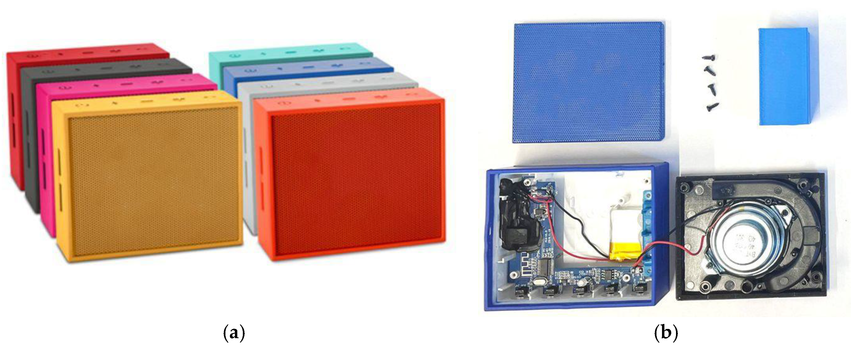
The considered Bluetooth loudspeakers are produced in eight colors as presented in
Figure 1a. After the disassembly process, four pieces are obtained: front aluminum cover, main plastic cover, electronic PCB, and the metal speaker covered by the black plastic membrane. In our framework system, speakers are represented by a metamodel of plastic cuboids (blue or orange) as presented in
Figure 1b. There are also speakers of different sizes and sound power, which are represented by a small cuboid. The applied metamodels in the form of cuboids reflect the primary features of the objects under consideration, such as size and color classes and sorting categories. The cuboid representation should therefore be interpreted as a task-oriented metamodel rather than as a full geometric representation of the dismantled loudspeaker components. The proposed validation procedure is dependent on the availability of discrete, sensor-detectable events and object descriptors that can be mapped between the source process and the resulting digital twin model, rather than on the cuboid shape itself. In this sense, the same event-based validation logic can be transferred to other sorting or disassembly cases, provided that relevant object classes, sensor events and process states are defined consistently.
It was assumed that larger speakers are more difficult to disassemble, as was proven in preliminary disassembly time studies.
The design of most Bluetooth speakers is similar to the example presented. Glued, pressed, soldered, and screwed connections are typically used; these require special tools and can make disassembly difficult.
No specific assumptions were made regarding manual tasks, but a standard level of skill, training, and ergonomics was assumed. The boundary conditions include a short warmup time (about 2 min) to fill the assembly line and a continuous flow of subsequent failed products without any pauses. Therefore, the parts create a time series of events that can be recorded by a photocell connected to a PLC. Discrete processes are then analyzed, the duration of which ranges from seconds to several minutes.
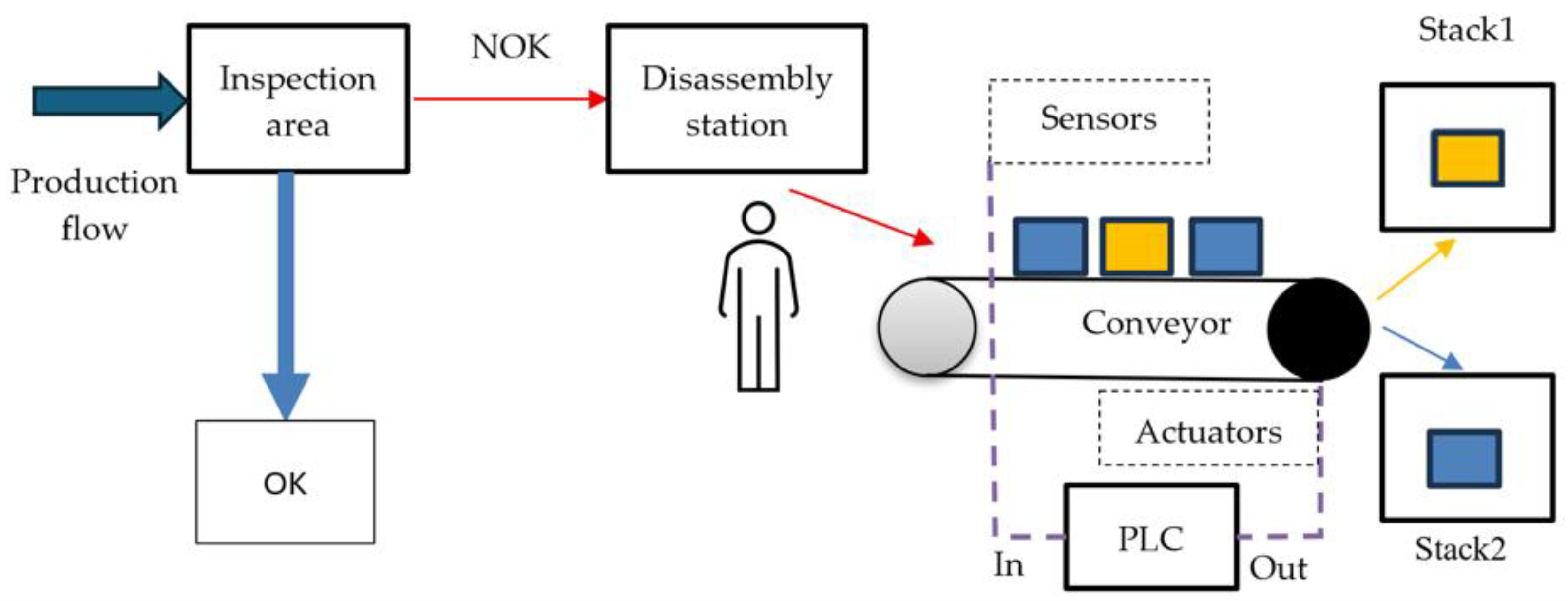
Figure 2 presents the concept of a disassembly workstation integrated with an automated component-sorting line controlled by a PLC.
Manufactured products are subjected to quality inspection, where the production flow is divided into two streams: OK and NOK. Products that do not meet quality requirements are sent to the disassembly station, where an employee performs manual disassembly. The operator then manually moves the dismantled elements onto the conveyor belt.
It was assumed that the sorting line would be based on a conveyor belt system controlled by a PLC, which processes input signals from sensors, such as photocells, and manages output devices, including actuators [
56,
57]. In the initial design phase, the system was intended to sort two categories of components distinguished by size and difficulty (small and large), each available in two color variants: light (orange) and dark (blue). The conveyor is integrated with a PLC-based automatic parts sorting system that receives signals from sensors, determines the type of component, and sends signals to the appropriate actuators to separate components into appropriate stacks. An optimization criterion was established whereby the sorting accuracy was required to exceed 90%.
2.2. Methodology of the Research
The adopted methodology is based on the progressive refinement of the initial concept, guided by design assumptions and the technical specifications of the applied components, in accordance with the Simulation Model-Based Systems Engineering (SMBSE) approach [
58]. This engineering framework integrates traditional modeling principles with dynamic system simulation techniques, including MiL, SiL, HiL, and digital twin techniques [
10,
59,
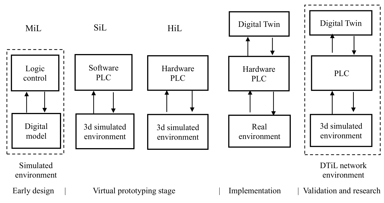
60], as illustrated in
Figure 3. The primary objective of SMBSE is to support the integrated design, analysis, and validation of complex systems within a unified model-based environment, enabling thorough evaluation prior to physical implementation.
Model in the Loop (MiL) is a simulation technique used in system engineering and software development to test control algorithms before writing final code or building physical hardware. Both the controller logic and the physical system are represented as digital software models and evaluated together in a purely simulated environment [
58].
In the next stage of prototyping the SiL (Software in the Loop) and HiL (Hardware in the Loop) validation techniques are used to assess PLC (Programmable Logic Controller) programs before deploying them to a physical factory floor. The key difference lies in the use of software or hardware controllers connected to a simulated environment that represents the real-world system. As a result, the controller executes its program as if it were operating a real system. However, instead of interacting with physical input and output devices, it exchanges signals with a simulated process model. Therefore, these methods ensure control of logic correctness, optimize cycle times, and prevent catastrophic equipment damage [
59,
60].
Typically, a simplified simulation environment within MiL/SiL/HiL is used. However, in this study the use of a 3D simulation environment is proposed, which can then be transformed into a digital twin. As the 3D simulation environment is an equivalent of the real environment, it can also be used to validate the digital twin within a networked simulation environment of Digital Twin in the Loop (DTiL). Thus, the DTiL approach extends the SiL/HiL technique by combining two simulation models that communicate via PLC signals, allowing the construction and validation of a digital twin in a network interface environment that simulates the real production environment.
The arrows in
Figure 3 indicate the direction of information flow: from internal model logic in MiL, through PLC-mediated signal exchange in SiL/HiL, to the DTiL stage, where source and resulting digital twin models are compared through a networked PLC communication path.
This configuration enables real-time testing of control logic, accounting for process dynamics and allowing verification of system responses to different scenarios. Moreover, it supports a shortened development cycle by enabling parallel hardware and software development and facilitating control algorithm optimization without disrupting ongoing production operations.
The 3D simulated environment used in the SiL/HiL method as a data source can also be used to build a DT model of the real industrial environment, because both models contain the same objects and look almost identical visually. Modification of control logic in the DT model is only required to receive signals from a (hardware or software) PLC [
55].
Validation of the digital twin is an important problem; therefore, following the SMBSE approach, previously developed models can be used together with a network interface to communicate with each other. As a result, we get a simulated network environment DTiL, in which digital twin communication channels and data structures can be tested.
The simulation model of the analyzed system is a representation of the knowledge about that system. It can be fed with empirical or synthetic data. In this paper, DTiL is used as a validation configuration in which a source model, a PLC-mediated communication path and a resulting digital twin model are connected under controlled and repeatable conditions. This use of DTiL is aligned with recent twin-in-the-loop and online-validation research but is focused here specifically on temporal fidelity of event streams in a DES-based manufacturing twin [
48,
49].
2.3. Case Study
To facilitate both conceptual and detailed design activities, as well as the development of PLC control logic, discrete process modeling and simulation were conducted using FlexSim 2024 with the Emulation module. This was combined with parallel PLC programming in the Siemens TIA Portal v19 environment, utilizing the PLCSim Advanced v6 virtual controller. Such an approach is consistent with the SiL method, which enables the testing and validation of PLC control software within a fully simulated environment, eliminating the need for physical hardware [
53].
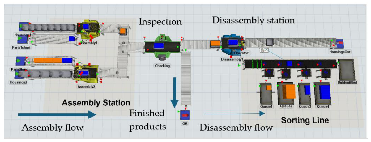
In the initial phase of the project, a conceptual model was created in the FlexSim 2024 environment, as illustrated in
Figure 4. The developed model encompasses assembly processes for multiple product variants, as well as inspection and disassembly operations for defective products. A model constructed this way allows for the synchronization of production processes and the inclusion of work-in-process [
32,
33].
The dismantled parts need to be sorted; therefore, the right-hand side of the figure shows a model of the sorting line, which was subjected to further design work.
Figure 4 is intended as a conceptual layout view of the simulated production and disassembly environment; the subsequent figures and tables provide detailed control and validation information.
2.3.1. MiL Model
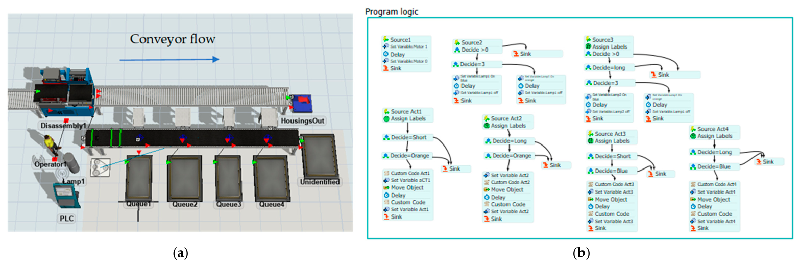
In the next stage, the logic for controlling the sorting process was developed using the Process Flow programming language with an internal data connection (internal server connection), as shown in
Figure 5. It enables emulation of PLC signals in FlexSim model according to the MiL method.
The control logic represented in
Figure 5b follows four main steps: object detection by the input photocell, identification of size and color class, assignment of the sorting category, and activation of the corresponding actuator when the object reaches the diverting position.
In this configuration, both the controller and the controlled process are represented entirely through software. By integrating controller emulation in FlexSim with real-time communication to the virtual PLC, the system can accurately reproduce PLC input and output signals. This significantly enhances the efficiency of program development and verification, allowing early detection of logical errors, thorough testing of control algorithms, and detailed analysis of system behavior under various operating scenarios [
35].
In the subsequent stage, a physical S7-1200 PLC was integrated with a simulated system developed in the FlexSim 2024 environment [
55]. The use of the SiL/HiL approach rep-resents an advanced engineering method for testing and validating control software under conditions closely resembling real industrial operation, prior to deployment in a physical installation. In conventional PLC development, testing is typically performed directly on the real system, which entails risks such as programming errors, production downtime, or potential equipment damage [
60].
2.3.2. SiL/HiL Modeling
In the next phase, the complete control logic for the sorting process was transferred to a virtual PLC using the TIA Portal v19 and PLCSim Advanced v6 environments. The software was initially tested locally (localhost) on a single workstation via the PLCSim transmission protocol, which made it possible to verify the PLC logic and eliminate errors. Subsequently, the operation of the modeled system was evaluated using a TCP/IP connection between two computers on a local network, employing the Siemens S7 communication protocol. The FlexSim 2024 simulation environment was run on one computer, while the virtual PLCSim controller operated on the other.
The tests confirmed correct program behavior in the simulated environment, known as Virtual Commissioning [
56,
61,
62], achieving 100% sorting accuracy. However, during the implementation stage, technical issues arose, as described in the following section.
2.3.3. Physical Prototype of the Sorting Line
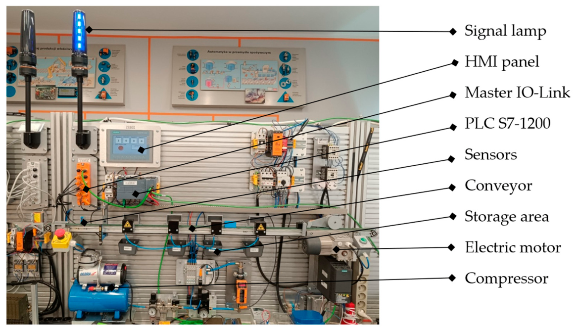
Based on the insights gained from earlier stages, a small-scale physical prototype was developed. Due to limited resources, certain design modifications were introduced to achieve a more compact form. A fully functional prototype of the component-sorting line, serving as a Proof of Concept (PoC), is presented in
Figure 6.
For the laboratory proof-of-concept prototype, the design guidelines were organized around three key flows: energy flow, material flow, and information flow [
55]. For the energy flow, three dedicated modules were created: a 230 VAC power distribution module (supplying the three-phase inverter driving the asynchronous motor that powers the conveyor belt), a 24 VDC power distribution module for the control system, and a compressed air preparation and distribution module (supplying the electro-pneumatic valves responsible for diverting components from the conveyor belt into magazines).
Once a block is correctly identified, it is routed to the appropriate container. The information flow comprises multiple parameters measured by industrial sensors integrated into the system. These process parameters were acquired using a Siemens S7-1200 controller, together with AL1306 series IO Link masters from ifm electronic.
The station collects data, including conveyor speed, distance traveled by each block, the block’s exact RGB color values, its longitudinal dimensions, the number of blocks in magazines 1–4, and the number of unidentified waste items. By using a Profinet network, the system enables smooth control of the gear motor’s start-up and braking ramps connected to the conveyor drive shaft, as well as flexible routing of information and effective management of the material flow.
2.3.4. Digital Twin of the Sorting Line
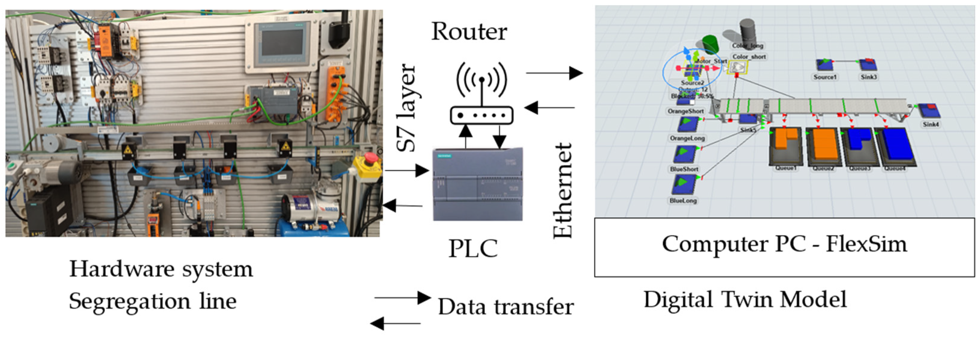
In the next step, a digital twin model of the parts sorting line was developed, as shown in
Figure 7, to reproduce the behavior of the actual system for validation purposes. The DT system architecture is based on a PLC controller and ethernet network connection between the PLC and PC computer with FlexSim software with emulation module.
Communication between the PLC and the digital twin model is similar to the HiL method and 3D simulation environment, but with the information flow reversed. The controller now sends output signals to the digital twin model based on input signals from real sensors located on the line.
Functional tests indicated that the digital twin model reproduced the expected sequence of sorting-line operations. In the next stage of research, we are analyzing data obtained through the digital twin model of the disassembled parts sorting line to validate models and confirm the results.
2.3.5. Validation of Digital Twin
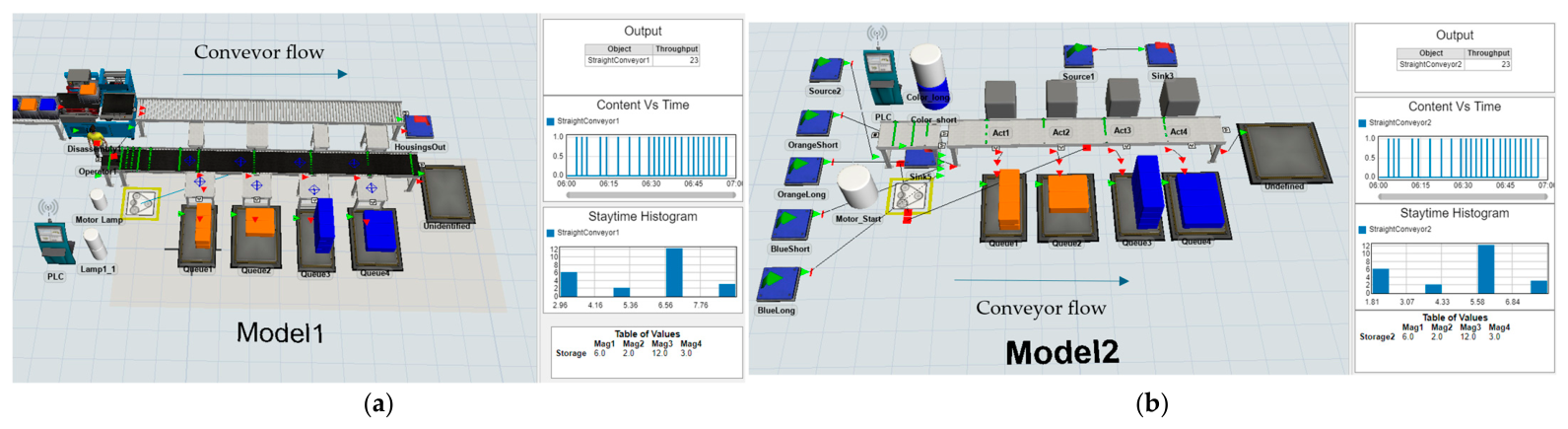
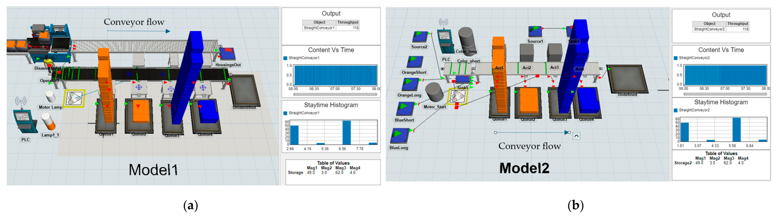
In the next stage of the research, the 3D simulation environment of the SiL/HiL method and the digital twin model were combined, which created digital twins in the loop. In this DTiL validation configuration, the source process was represented by Model 1 in FlexSim, while Model 2 represented the resulting digital twin. The signal exchange between the two models was mediated by the virtual Siemens S7-1500 (Germany) controller running in PLCSim Advanced v6 over a local network. This configuration was used for the quantitative temporal-fidelity results reported in
Table 1 and
Table 2. For reproducibility, the validation workflow was carried out in the following order: (1) the source FlexSim model and the resulting digital twin model were configured with the same object classes, sensor states, and sorting categories; (2) the source model was run either with the empirical operator-time series or with the constant 60 s takt sequence; (3) photocell and object-descriptor signals were transferred through the virtual S7-1500 controller in PLCSim Advanced v6 over the local network; (4) photocell rising-edge timestamps were recorded in both models and exported as event histories; (5) events were matched by occurrence order and checked using size, color, and sorting-category descriptors; (6) runs with missing, duplicated, or reordered events were excluded; and (7) absolute event delay and inter-event timing differences were calculated for the matched events. A digital model represents knowledge of the system being analyzed and can also be a source of data for a digital twin of the system as shown in
Figure 8.
Figure 8a shows source model 1, which was built according to the disassembly system 3D simulation environment based on empirical data obtained during a time study (
Appendix A). This model serves as a signal source for the PLC control system, similar to SiL/HiL methods.
Figure 8b shows model 2, which represents the digital twin of the system that reproduces the real-time operation of model 1 based on signals from the PLC control system.
Figure 8 is used to illustrate the DTiL validation configuration and the direction of event transfer between the source and resulting models; the quantitative synchronization indicators are reported in
Section 3.
Photocell-event matching was performed using event order as the primary criterion and object descriptors as a consistency check. First, all photocell rising-edge events were indexed separately in the source model and in the resulting model according to their occurrence order. Second, each indexed event was associated with an object descriptor derived from subsequent sensor signals, including size class, color class, and sorting category. Runs containing missing events, duplicated events, or order inconsistencies were excluded from the quantitative delay analysis; no interpolation or manual correction of missing events was applied.
The exported simulation timestamps had a numerical resolution of 0.01 s, which was sufficient for storing and comparing event histories after acquisition. This value should not be interpreted as the effective temporal accuracy of the PLC-mediated event transfer. The effective temporal resolution of the replicated event stream was primarily constrained by the FlexSim sampling interval of 500 ms, together with polling, model update logic, and communication delay.
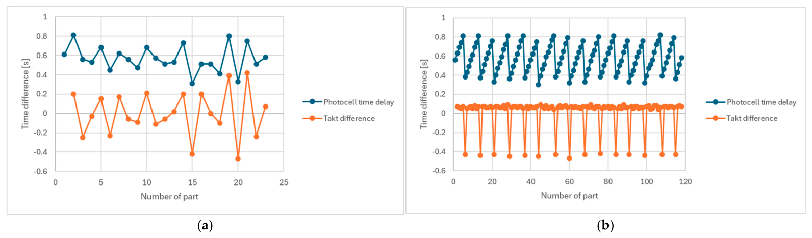
To evaluate the results and observed fluctuations, another experiment was performed, using synthetic data with a constant takt time = 60 s, 118 elements, and a simulation time of 2 h, as shown in
Figure 9.
Figure 9 illustrates the synchronization between the source and resulting models for the controlled constant-takt experiment. A quantitative assessment of temporal fidelity is presented in the following section using the event-delay and inter-event timing metrics summarized in
Table 1 and
Table 2 and
Figure 10. Therefore, this approach enables the comparison of the performance characteristics of both digital twin models and provides a framework for validation and further research under controlled and repeatable conditions, eliminating the influence of random human factors. A detailed analysis of the results is presented in the next section.
3. Results
Data obtained from a PLC is in the form of a time series. Time series analysis and forecasting are crucial for the efficient operation and decision-making processes of various industrial systems. Accurately predicting future trends is essential for resource optimization, production scheduling, and overall system performance [
63,
64].
Two complementary types of measures were used. The first is absolute event delay, defined as the time difference between a selected photocell event timestamp in the source model
and the corresponding timestamp in the resulting model
:
The second measure is based on inter-event timing. If
and
, then
The main reason for analyzing Δτi is that it reduces the effect of initial clock mismatch. In practice, the two models were not started at exactly the same instant, so comparing raw timestamps would include an offset unrelated to the actual quality of replication. Aggregated takt statistics (minimum, mean, and maximum) were also compared between the two models.
The one-hour replication study yielded 23 matched photocell events for which absolute event delay could be evaluated.
Table 1 summarizes the results from the best and worst replications. It also shows comparative results for the constant-takt scenario. The additional constant-takt experiment was introduced as a controlled reference case rather than as a replacement for broader physical validation. The empirical one-hour run represents realistic manual-process variability, whereas the constant-takt experiment removes operator-induced variability and makes it possible to assess PLC-mediated replication effects under repeatable input conditions. Therefore, both experiments should be interpreted jointly, with the empirical run demonstrating proof-of-concept under realistic conditions and the constant-takt run providing a controlled assessment of temporal synchronization.
Temporal fidelity was evaluated using two complementary metrics: absolute event delay, which captures timestamp-level shift, and inter-event timing difference, which captures rhythm-level preservation relevant to takt-time analysis.
The mean absolute delay was about 0.566–0.860 s, while the maximum observed delay reached 1.57 s. These values are consistent with the observations reported from other experiment replications, where typically signal delays of about 0.3–0.8 s were observed under the same settings. The worst replication additionally shows that larger outliers may also occur in repeated runs.
For the quantitative mapping analysis, timestamps of photocell-detection events were exported from both models with a numerical resolution of 0.01 s. The effective temporal resolution of the event transfer was nevertheless constrained by the 500 ms FlexSim sampling interval, the average S7-1500 PLC cycle of approximately 2 ms, and the data transmission delay between the computer and the router of approximately 1 ms.
In the subsequent study, only the time differences between successive signals were analyzed, which helps eliminate clock synchronization errors. Signals received from the PLC based on photocell readings constitute a time series, and the intervals between consecutive events are treated here as event-based takt-time measurements of the operator/process rhythm. The manual disassembly process is characterized by significantly greater variability in work time than in the assembly process; the resulting minimum, average, and maximum takt time is shown in
Table 2.
Figure 10 presents graphs comparing the time differences of source and output photocell events for two experiments, including variable and constant takt time along with the delay between events and the synchronization error between events in the form of the takt time difference.
Both graphs show some fluctuations, which are more regular for the constant-takt simulation. The observed delays are typically fractions of a second, as shown in
Table 1 and
Table 2. The mean takt difference between the two models was only about 0.002 s in the best replication and about 0.02 s in the worst replication. The maximum takt differs by about 0.03–0.55 s, while the minimum takt differs by 0.08–0.1 s. These results show that, although absolute event timestamps drift, the overall rhythm of the process is reproduced well. The other replication does not reproduce the same aggregate values, but it leads to the same practical conclusion: the event stream received through the PLC-mediated chain preserves the process rhythm sufficiently well for takt-based analysis.
The observed pattern of disturbance changes (
Figure 10b) can be used to determine the disassembly process parameters more accurately.
These results indicate that, under the tested local-network DTiL configuration, absolute event timestamps may drift while aggregate inter-event statistics remain close between the source and resulting models. Therefore, the replicated event stream can support takt-oriented analysis in the studied scenario. However, broader validation is required before the approach can be generalized as an online monitoring or decision-support method for industrial operation.
4. Discussion
The presented approach enables conducting repeatable simulation experiments in a stable network environment based on empirical data. The same input data were used in each replication; therefore, the influence of random human factors on process variability in subsequent replications can be omitted.
The delay levels obtained should be read together with the configuration parameters.
The signal sampling interval in FlexSim was 500 ms, while the mean PLC cycle was around 2 ms and the node-to-router delay was around 1 ms. This means that the dominant source of visible drift is not the controller scan itself, but the combined effect of periodic sampling, polling, model update logic, and the communication chain. From the user’s point of view, the observed 0.6 s average delay is therefore an effect of the whole replication path, rather than only “network latency”. In the case of long-term manual processes, the observed delay is much smaller than the impact of variable human factors.
This distinction is also important for future takt-time prediction because a predictive model should learn process-induced timing patterns rather than artefacts introduced by sampling, polling, or communication delays.
The initial clock mismatch effect is related to the internal clock of the simulation software, which operates independently of the real-time clock, but the time flow remains 1:1.
It is also worth noting that the discrepancy pattern is not uniform across all aggregate measures. The minimum takt differs more visibly than the mean and maximum values, which suggests that short local fluctuations are more sensitive to sampling and updating order than the overall rhythm seen over longer intervals. This observation is consistent with the process character of the studied system: manual work and sensor-triggered events create a sequence in which small local timing deviations can appear without changing the average takt over a longer run. For that reason, the results should be interpreted on two levels at once: event delay remains relevant whenever individual reactions matter, but the preservation of mean takt indicates that the twin still captures the dominant pace of the process.
From the validation point of view, the reported results therefore show that fidelity should be assessed on two levels. Absolute event delay quantifies how far the replicated event stream is shifted in time. Inter-event measures indicate whether this shifted stream still preserves the production rhythm sufficiently well to remain analytically useful. In the studied case, the first measure warns against treating strict simultaneity too literally, whereas the second confirms that the twin remains informative for takt-oriented process assessment. Thus, absolute event delay becomes the dominant metric when the digital twin is used for event-triggered reactions, sequence-dependent actuation, alarm generation, or functions that require synchronization with the current physical state. Inter-event timing becomes the dominant metric when the objective is to analyze process rhythm, takt-time stability, operator-dependent variability, or long-cycle throughput, where a nearly uniform time shift is less important than distortion of the intervals between consecutive events.
The acceptability of temporal error should be defined in relation to the intended use of the digital twin. The observed delays would be unacceptable without compensation in applications that require deterministic synchronization with the physical process, such as closed-loop control, fast actuator triggering, sequence- or collision-critical operations, safety-related functions, or alarm logic with strict reaction-time limits. In such cases, absolute event delay rather than aggregate rhythm preservation would define the practical limit of the DTiL configuration. In the present long-cycle manual disassembly case, however, the objective is takt-oriented monitoring rather than direct real-time control; therefore, inter-event rhythm preservation is the relevant criterion, provided that event order and aggregate statistics are preserved. Since the shortest observed empirical takt time was about 101.71 s, the mean absolute event delay of 0.566–0.860 s corresponds to less than 1% of this takt, while the maximum observed delay of 1.57 s remains below 2%. At the rhythm level, the maximum inter-event takt difference of 0.55 s corresponds to approximately 0.54% of the shortest observed takt, and the mean takt differences remain below 0.02 s. Therefore, in this study, the replicated event stream can be considered temporally acceptable for aggregate takt-time analysis, but not as evidence of strict timestamp-level synchronization.
This interpretation is consistent with the broader logic of in-process monitoring, where temporal signal patterns are analyzed to distinguish process-related signatures from noise, disturbances, or measurement artefacts. In EDM, for example, in situ monitoring and discharge-pulse analysis are used to identify process states and abnormal conditions from time-dependent signal behavior [
65]. In the present manual disassembly and sorting case, the measured signal is not an electrical discharge waveform, but a PLC-mediated sequence of photocell events. Nevertheless, the same conceptual distinction is relevant: process-induced timing signatures, such as operator-dependent work rhythm or product-dependent task duration, should be separated from artefacts introduced by sampling, polling, initial clock mismatch, or communication delay.
The results suggest that, for long manual operations in the tested local-network configuration, inter-event rhythm can remain informative despite visible timestamp drift. This supports the preliminary use of the DTiL setup for takt-oriented monitoring. In future work, such event-based rhythm measures may also complement operator-related performance or reliability assessment discussed in [
66]. However, broader validation is still required before making general claims about real-time decision support or operator-related reliability assessment.
However, further research is required for a longer simulation period, which is associated with a greater risk of signal interference and delays in a wide area network and may result in increased mapping error. Therefore, further research is also planned to compare the performance of the virtual controller with the hardware controller for different signal sampling rates and other communication protocols.
Other research directions include acquiring data from multiple sources [
67] and reinforcement learning for the prediction of changes in a process [
68].
5. Conclusions
The study demonstrates the preliminary feasibility of combining MiL, SiL, HiL, and DTiL stages for the development and temporal-fidelity assessment of a PLC-mediated digital twin under controlled local-network conditions. Rather than confirming general temporal accuracy, the results show how absolute event delay and inter-event rhythm preservation can be assessed separately in a DES-based manufacturing twin.
The article extends a simulation-based digital twin methodology toward the problem of temporal fidelity in manufacturing systems. Rather than reducing the issue to protocol latency, it examined how a FlexSim-based digital twin reproduces the timing of PLC-mediated events in a networked DTiL replication environment. Three conclusions can be drawn. Firstly, visible absolute delay exists: in the analyzed replication the mean event delay was about 0.6 s and the maximum delay about 1.57 s. Secondly, these values do not translate directly into poor operational fidelity, because inter-event timing and aggregated takt statistics remained very close in the source and resulting models. Finally, for the tested long-cycle takt-monitoring task, preserving process rhythm was more informative than requiring exact timestamp equality.
The scientific contributions of this article include the following:
A DTiL validation stage for assessing PLC-mediated temporal fidelity, with explicit separation between absolute event delay and inter-event rhythm preservation; and,
A two-level synchronization assessment distinguishing timestamp-level delay from rhythm-level takt preservation.
Engineering implementation includes the following:
Step-by-step implementation of a PLC system, including the use of MiL, SiL, HiL, and DT techniques;
Working DT of a PLC-based sorting system, made in FlexSim; and,
Experimental validation of DTiL models in the tested local-network environment.
The proposed workflow demonstrates preliminary feasibility under a local-network and controlled simulation configuration. The S7-1200 prototype was used to demonstrate the laboratory implementation of the disassembly and sorting line and the acquisition of process data from a PLC-based system. The quantitative timing analysis was then carried out in the DTiL setup, where two FlexSim models exchanged events through a virtual S7-1500 controller. The results should therefore be interpreted as a proof-of-concept validation of the proposed temporal-fidelity assessment procedure in the tested configuration, rather than as a general validation of temporal accuracy for all PLC-based digital twin implementations. The generalizability of this approach remains limited by the assumption of continuous disassembly, without interruptions in the operator’s work, and by the local-network communication conditions. Network communication disruptions and lost or duplicated PLC signals can distort the obtained results, especially in wide area networks. Therefore, future validation should include longer manual runs, additional product variants, repeated tests with different operators, and sensitivity analysis under controlled network constraints, including increased communication workload, different sampling intervals, packet delay or jitter, hardware-controller configurations, and alternative PLC protocols.
The transferable part of the proposed methodology is the event-based validation logic: definition of a source event stream, PLC-mediated event transfer, event matching between the source and resulting models, and separate calculation of absolute event delay and inter-event timing differences. These steps can be applied to other discrete sorting or disassembly systems if comparable sensor events, object descriptors, and process states are available. In contrast, the numerical delay values reported in this paper are configuration-specific. They depend on the FlexSim sampling interval and model update logic, the PLCSim Advanced virtual S7-1500 controller, the Siemens S7 communication path and the tested local-network conditions.
Further research is planned to include the creation of a full-scale installation for the reuse of disassembled parts and the development of a digital twin model of the sorting line with a physical PLC S7-1500.
For future takt time prediction, a two-level fidelity assessment can be combined with interpretable data-driven modeling, where global and local model inspections are used to verify that predictive decisions are driven by relevant process variables and not by sampling, probing, or communication latency artifacts. Therefore, prediction of manual disassembly takt time with the use of machine learning and integration with an ERP database is also planned.