1. Introduction
The IoT has become an indispensable part of modern life, with applications in smart homes, health monitoring, traffic control, smart grids, and smart factories [
1]. Based on some standardized Internet protocols, massive devices can be easily integrated into IoT networks [
2]. The IoT systems include not only electronic modules and micro-controller units but also living entities such as plants, animals, and humans. They are designed to enable seamless global connectivity, although this increasing automation may reduce direct human interaction [
3]. As a key component of the Fourth Industrial Revolution, IoT relies heavily on wireless communication technologies, primarily those based on RF waves, such as LoRa, ZigBee, Wi-Fi, and Sigfox, to enable worldwide interconnection. However, a lot of concerns have been raised regarding the potential health effects of electromagnetic RF radiation, particularly in sensitive environments such as schools and hospitals. To address these concerns, researchers are exploring safer and more effective alternatives to conventional RF-based communication systems.
OWC has emerged as a substitute for traditional RF-based systems by leveraging the visible light spectrum for data transmission. OWC technologies are primarily categorized into three methodologies: Visible Light Communication (VLC), Light Fidelity (Li-Fi), and optical camera communication (OCC). While VLC and Li-Fi rely on photodiodes to sense LED intensity variations, OCC utilizes image sensors—specifically rolling shutter or global shutter cameras—as receivers [
4]. Compared with RF-based systems, OWC offers several advantages:
Motivated by these advantages, significant research efforts have been devoted to the development of OWC technologies. The IEEE 802.15.7-2011 standard [
6] originally defined OWC protocols with a focus on VLC. The revised IEEE 802.15.7-2018 standard [
7] expanded this framework to include: VLC (detailed in the 2011 standard) and OCC (using image sensors or cameras to receive data from light sources).
LEDs are well-suited for next-generation OWC systems due to advances in LED technology, including long operational lifetimes, high energy efficiency, and fast switching speeds [
8,
9]. Although RF-based systems remain widely used in communication and monitoring applications, their sensitivity to electromagnetic interference and potential biological effects pose significant challenges. In contrast, OWC systems do not generate electromagnetic interference, making them an attractive alternative. In VLC and LiFi systems, LEDs typically transmit data using OOK modulation, which is detected by photodiodes. The application of MIMO techniques has further improved data throughput in these systems. However, photodiode-based OWC systems are generally limited to short-range indoor communication due to signal degradation in outdoor environments. In contrast, OCC systems offer advantages in terms of transmission range, as they employ camera image sensors for reception and have demonstrated successful communication over much longer distances, reportedly up to 300 m [
10]. The performance of OCC systems depends strongly on the type of image sensor used [
11]. Rolling shutter-based systems rely on frame rate and rolling shutter speed, whereas global shutter cameras require the frame rate and packet rate to satisfy the Nyquist sampling requirement [
12]. To achieve longer communication distances, parameters such as signal-to-noise ratio (SNR), camera focal length, and exposure time must be carefully optimized. Currently, LiFi systems achieve data transmission distances of up to approximately 10 m using photodiode-based receivers [
13], whereas OCC continues to extend its communication range, making it a strong candidate for future optical wireless communication systems.
In OCC systems, MIMO techniques enable simultaneous data transmission from multiple light sources to a camera receiver, which do not work well in photodiodes. Within OCC frameworks, region-of-interest (RoI) signaling algorithms [
14,
15,
16] are commonly employed to allow the receiver to identify and process multiple light sources that are simultaneously visible within the camera’s field of view. Besides that, OCC can support better performance, by considering mobility environment, compared to VLC/LiFi systems.
A variety of modulation techniques for OCC have been published in the existing literature. One method exploits the rolling shutter effect to implement OOK modulation; however, this approach is limited by a short operating range and reduced performance. To address low data rates, rolling orthogonal frequency-division multiplexing (rolling shutter-OFDM) was introduced in [
17,
18]. Similarly, the system proposed in [
19] employs a MIMO scheme based on color intensity modulation using a high-speed global shutter camera operating at 330 frames per second (fps). In addition, global shutter cameras are expensive and not widely available, and the use of color channels introduces higher bit error rate (BER) and reduced range compared with OOK-based systems. The localization of IoT devices is one area of important work in IoT systems; Refs. [
20,
21] introduced the localization algorithms in integrated sensing and communication to improve communication performances. Our work showed reliable communication performance at transmission distances of up to 22 m under various mobility conditions. Furthermore, the proposed system is validated through real-time environmental data transmission using temperature and humidity sensors with 20 links. It makes sure that it is suitable for industrial IoT smart city applications by supporting any type of cameras in the market. Besides that, we can scale up to a hundred connectivity links in big area IoT.
This study presents a 2D-MIMO OCC system based on LED arrays for IoT applications. The proposed system focuses on improving communication reliability in practical mobility environments while maintaining compatibility with commercially available cameras. The main contributions of this work are summarized as follows:
Suitable for almost all commercial cameras: The proposed system supports both rolling shutter and global shutter cameras through the combination of RoI detection and adaptive exposure control.
Data synchronization: To address frame rate variations in real OCC system, a sequence number-based synchronization algorithm is proposed. This method enables the receiver to identify packet loss, duplication, and timing mismatches during the decoding process.
Mobility support: The proposed system is evaluated under different transmission distances, camera types, and mobility conditions. By applying YOLOv13 for LED detection instead of conventional algorithms, we can support a high-mobility environment to improve OCC performance.
Deep learning decoder: A deep learning-based decoding method is employed to improve OCC performance under various noise and mobility conditions. The proposed approach is evaluated and compared with conventional zero-crossing decoding methods.
Multi-link support: By applying deep learning, we can support simultaneous multi-links at long distance and mobility environments with low bit error rate.
The remainder of this paper is organized as follows. The technical architecture and system design are detailed in
Section 2. Evaluation of the system performance through experimental results is presented in
Section 3. Finally,
Section 4 provides a summary and concludes this study.
2. System Design
The main architecture of the proposed OCC scheme is based on the control of light intensity to enable data transmission. A key aspect of this design is the modulation scheme, which directly affects system throughput and link reliability. OOK stands as a prevalent modulation method favored for its straight-forward implementation. As an amplitude-shift keying (ASK), OOK encodes binary information through two distinct light levels: an ‘ON’ state for bit ‘1’ and an ‘OFF’ state for bit ‘0’.
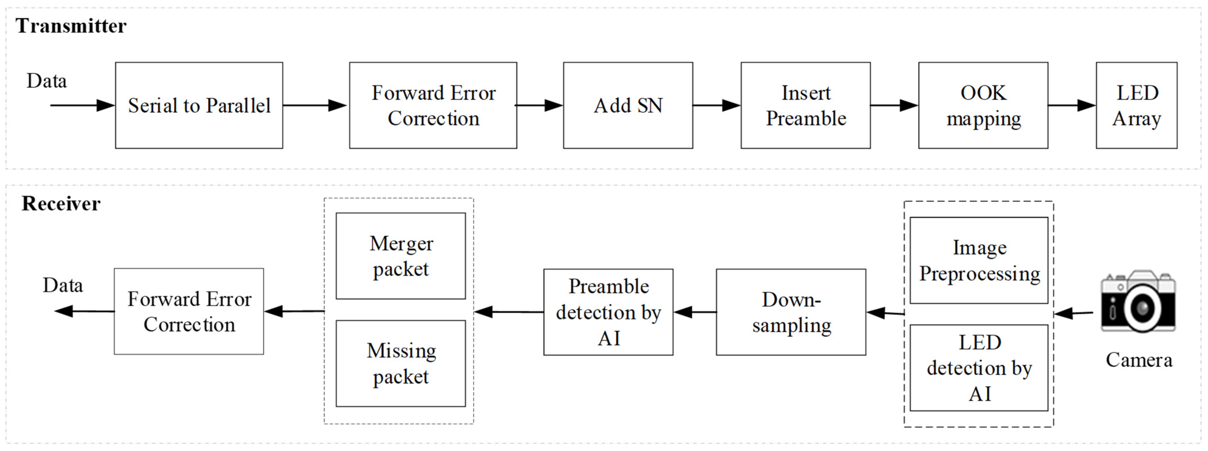
In this study, an LED matrix-based OCC scheme is proposed for IoT applications. The LED array is arranged in a spatial frame format that enables efficient data detection and decoding using RoI algorithms. Each LED in the array functions as an independent light source and transmission channel, enabling simultaneous multi-channel data transmission. The system architecture of the proposed system is illustrated in
Figure 1, which presents the OOK-based 2D MIMO transceiver architecture and highlights the interaction between the transmitter (LED array) and the receiver (camera). The following subsections describe the functional components and processing flow of the system, including data encoding, LED control, image acquisition, signal processing, and data decoding. The proposed architecture is designed for interoperability with commercial cameras and incorporates several technical enhancements.
2.1. Channel Coding
Channel coding, or Forward Error Correction (FEC), is a fundamental element in digital systems, primarily used to reduce bit errors during transmission. This algorithm functions by appending parity information to the data stream at the source, allowing the receiver to reconstruct the original message despite the presence of distortion and noise. From the proposed architecture, we apply a coding scheme to the LED matrix’s configuration, ensuring stable communication and enhanced data decoding.
2.2. Start-of-Frame and Sequence Number Insertion
To synchronize the sequence data frame and detect the received signal at the receiver, a synchronization part and a header frame are inserted into each data packet. Although the preamble does not carry information, it is necessary for reliable frame alignment. The preamble length is optimized to ensure accurate frame detection while minimizing overhead.
In this work, a 6-bit preamble Synchronization Field (SF = “011100”) is employed, providing a clear reference for frame detection in each received image. Following the preamble, each data packet includes a sequence number (SN) to synchronize and detect the potential frame rate mismatches between the transmitter and the receiver. The SN enables identification of missing packets due to undersampling, elimination of redundant packets caused by oversampling, and reconstruction of large data packets from adjacent frames. The performance impact of the SN part is discussed in
Section 4.
2.3. LED Detection
Instead of relying on conventional RoI-based detection methods, a deep learning-based LED detection using YOLOv13 algorithm is implemented to accurately detect LED arrays in each received image and to maintain stable identification in a real-time environment. Frame structure of the proposed scheme includes two primary parts: (i) anchor LEDs, corresponding to the four corner LEDs that remain continuously illuminated and serve as geometric reference points, and (ii) data LEDs, which transmit information. The dataset of YOLOv13 includes 10,000 images captured under varying real-time conditions, including transmission distances from 2 to 22 m, different illumination levels, background light, camera parameters (exposure time, contracts, brightness, focal length, etc.), and motion blur. The images in dataset are split into training, validation, and test datasets with by following ratio: 60% dataset for training, 20% dataset for validation, and 20% for test model. Data augmentation techniques such as Gaussian blur, random brightness and contrast adjustments were applied to improve model robustness. During real-time operation, each camera frame is processed by the YOLOv13 model to generate bounding boxes, confidence scores, and class labels.
The Deep Simple Online and Realtime Tracking (Deep SORT) algorithm assigns a stable track ID to each detected LED, ensuring consistent channel association across frames. The RoI corresponding to each track ID is extracted and stored in a temporal buffer to form an intensity sequence over time. This sequence is subsequently passed to signal processing modules, including downsampling, deep learning-based decoder and preamble detection, and SN-based packet reconstruction. This approach differs from conventional RoI methods, which rely on static thresholding or manual calibration, by enabling adaptive and robust LED localization in dynamic environments.
The integration of YOLOv13 and Deep SORT provides several benefits:
Improved RoI detection accuracy under varying lighting and background conditions;
Supporting multi-LED and multi-user scenarios;
Enhanced signal consistency, resulting in reduced BER prior to OOK demodulation.
Experimental parameters include image input resolution, confidence and Intersection over Union (IoU) thresholds, average inference latency per frame, and anchor LED detection accuracy.
2.4. Deep Learning Decoding
Communication performance degrades as transmission distance increases due to a reduction in SNR values, making it difficult to reliably distinguish between ON and OFF signal states. To address this limitation and extend the communication range, an enhanced signal detection approach is required in place of conventional methods. In wireless transmission, matched filtering is extensively employed as an optimal linear method for SNR maximization. Its widespread adoption algorithms form a balance between operational simplicity and its effectiveness against background noise. The IEEE Std 802.15.7a-2024 standard [
18] recommends matched filtering for OCC systems to improve signal reliability. However, in mobility environments, we need other methods to apply in the OCC system to achieve good performance. Although deep learning [
22,
23,
24,
25] is the future for OCC decoding, this work presents a deep learning-based alternative that outperforms standard matched filtering in current applications. By applying DL decoding, we can achieve 98% accuracy at 3 m/s velocity, at transmission distances of up to 22 m under various mobility conditions. Furthermore, the proposed system is validated through real-time environmental data transmission with 20 links.
After LED detection, OCC signals are recovered from multiple light sources via a downsampling technique, whereby a 2D MIMO is generated by sampling the central intensity of each LED. The proposed system is evaluated on a dataset of 10,000 raw samples (including preamble and payload), captured using two camera types (rolling/global shutter cameras) at distances between 2 and 22 m under varying motion conditions. The signals in dataset are split by the following ratio: 80% dataset for training, 15% dataset for validation, and 15% for test model.
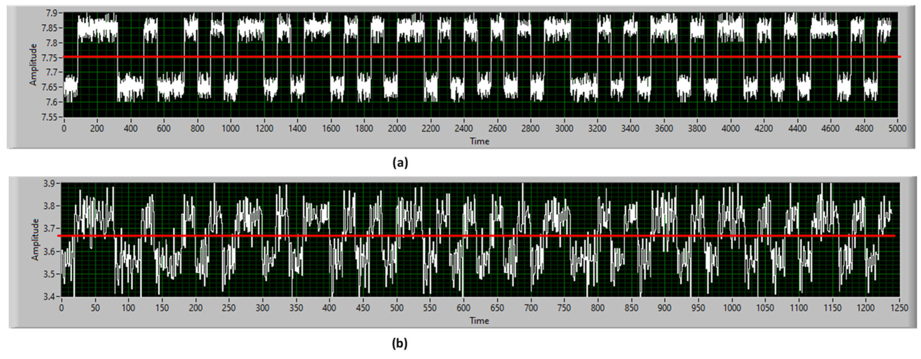
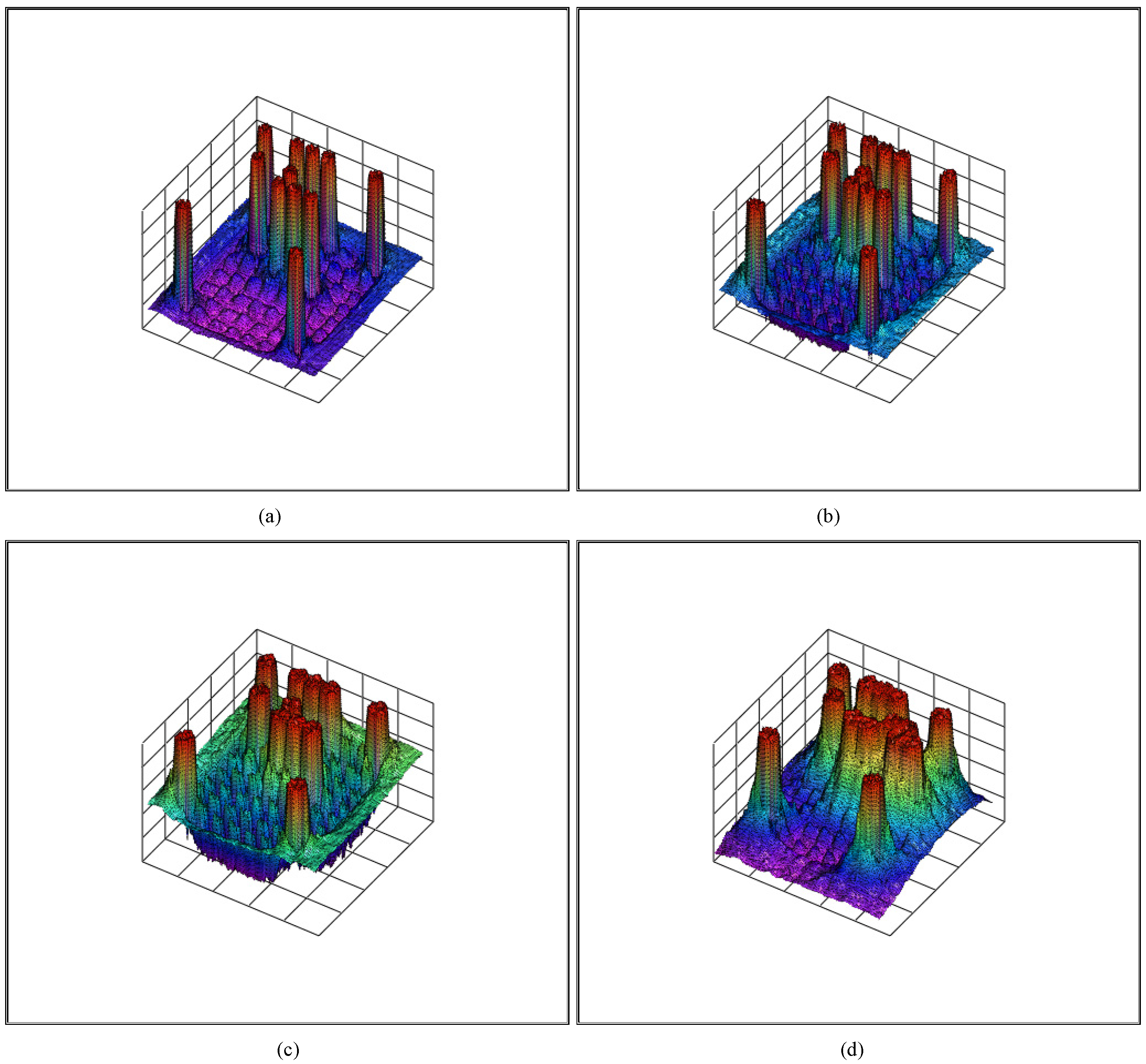
Figure 2 shows the experimental result of 2D OOK-MIMO signals with (a) high SNR and (b) low SNR. With long distance, the SNR values will reduce, making it difficult to recognize the threshold value at the receiver side. The deep learning decoder architecture, depicted in
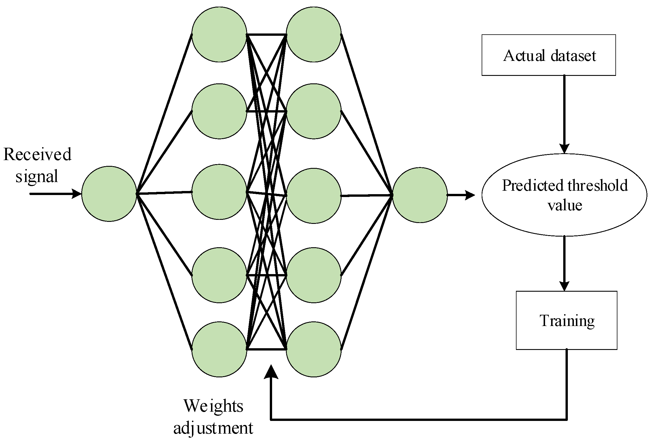
Figure 3, incorporates only two hidden layers to maintain a low model complexity and prevent overfitting during the training process. After preamble detection, the DL model accurately estimates threshold values for the 2D-MIMO signals, resulting in improved decoding performance compared with conventional techniques in mobile environments. Increasing to over five hidden layers in the DL model resulted in overfitting and reduced performance on the test dataset.
Figure 3 illustrates the deep learning-based decoder model, which predicts threshold values instead of relying on conventional algorithms.
3. Implementation
3.1. Noise Modeling and Pixel-Eb/N0
In Complementary Metal-Oxide-Semiconductor (CMOS) and Charge-Coupled Device (CCD) image sensors, pixel-level noise is commonly modeled as a Gaussian distribution. Following the stochastic framework established in [
26], the noise component n is modeled as follows:
where
denotes the received pixel intensity, and the noise variance
is defined by
, where a represents the amplitude difference between the mark and space logic levels. The fitting coefficients
and
are system-specific parameters determined through experimental calibration, following the procedure described in [
27].
To evaluate signal quality at the receiver, the pixel-level energy-to-noise ratio
should be computed. Assuming a one-bit-per-symbol mapping, the estimated expression is given by
The parameters in Equation (2) are defined as follows:
The parameters and correspond to the energy associated with each bit and the noise’s power spectral density.
∆ is the ratio of the exposure time to the bit , defined as .
and are hardware-dependent constants determined through curve fitting during the initial system calibration phase.
3.2. Experimental Analysis of SNR Values
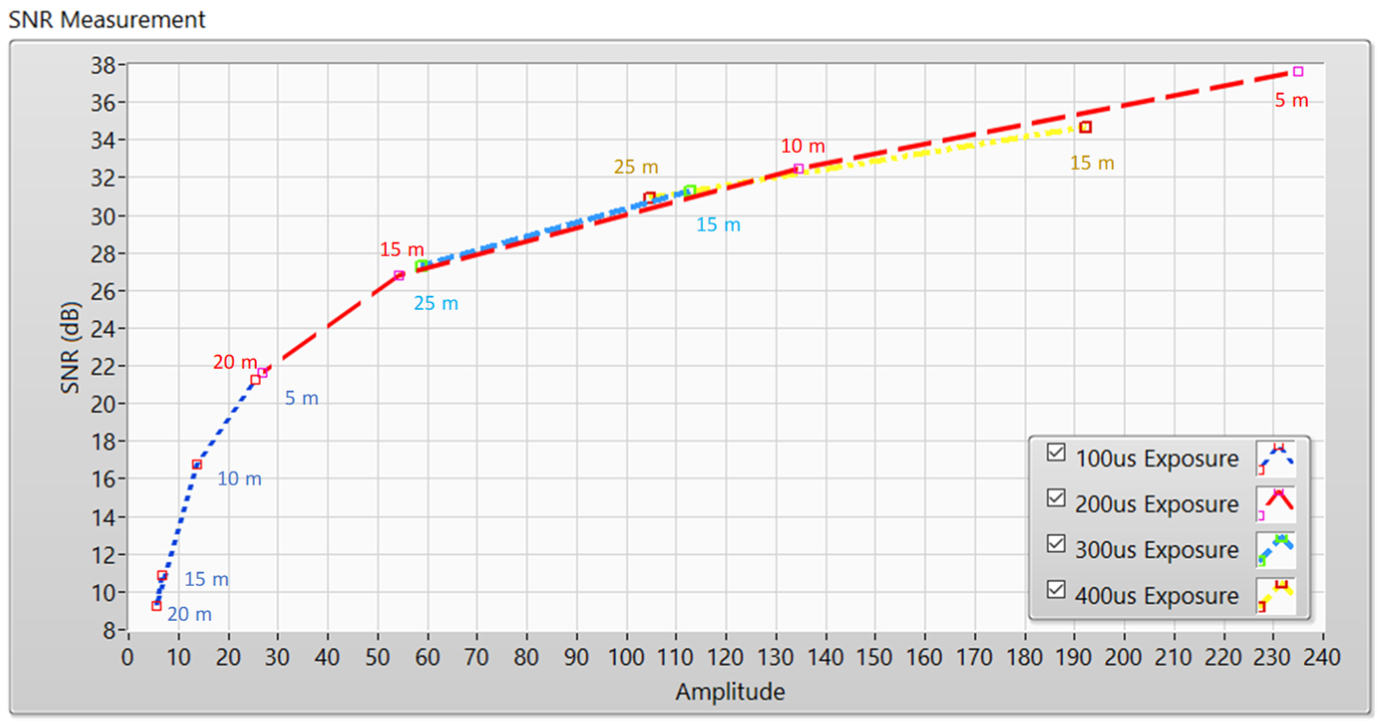
To evaluate the stability of the proposed system, an analysis of the SNR was processed under varying communication distances and camera exposure times. The primary objective of this analysis was to characterize the trade-off between the transmission range and BER by adjusting the camera’s exposure settings.
Experimental Configuration and Setup:
The camera exposure time was incrementally varied from to to examine its effect on the pixel-level energy-to-noise ratio with distances ranging from 5 to 25 m. As transmission distance increases, the optical signal intensity captured by the CMOS sensor decreases. Increasing exposure time improves signal acquisition by accumulating more optical energy; however, this improvement must be balanced against potential issues such as sensor saturation and inter-symbol interference.
For an analysis of signal quality in a real-time environment, the SNR values were obtained at different communication ranges of 5, 10, 15, 20, and 25 m. The measurement procedure alternated the LED array states between “ON” (active transmission) and “OFF” (background reference) to separate signal power from ambient noise.
When the LEDs are in the “ON” status, the measured signal corresponds to the emitted power. In contrast, measurements obtained during the “OFF” state establish the baseline noise for each distance. The experimental SNR, expressed in decibels (dB), is calculated using the root-mean-square (RMS) formulation given by
where
is the discrete power sample extracted from the LED array,
denotes the recorded ambient noise power levels,
n represents the cumulative count of samples gathered throughout the observation period.
As indicated in Equation (3), by increasing the camera exposure time, we can improve SNR values, but it reduces the bandwidth of the system. However, a relationship is observed between communication distance and signal quality. The measured SNR values decrease as the transmitter-to-receiver distance increases.
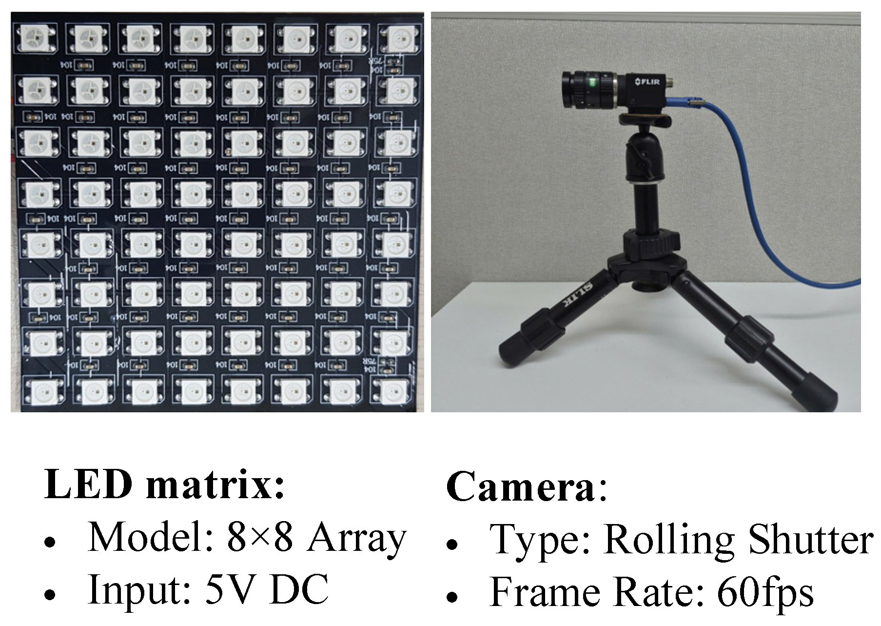
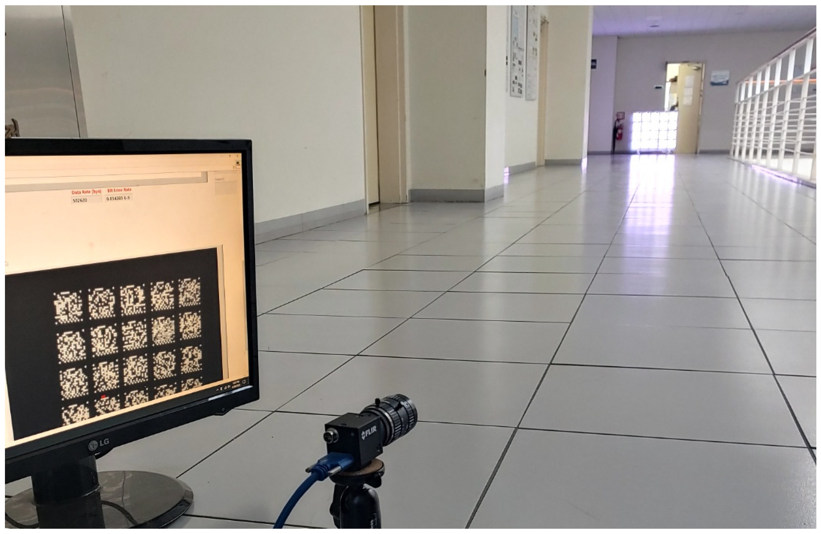
Figure 4 illustrates the experimental setup used to measure SNR, while
Figure 5 presents the measured SNR values over distances from 5 to 25 m under different exposure times.
3.3. Bit Error Rate (BER) Analysis for Optical OOK Modulation
The transformation of the received optical signal into its electrical equivalent, denoted as
r(
t), can be mathematically formulated as follows within the OOK framework:
Here
∈ {0, 1} denotes the
i-th OOK symbol level, while
g(
t) and
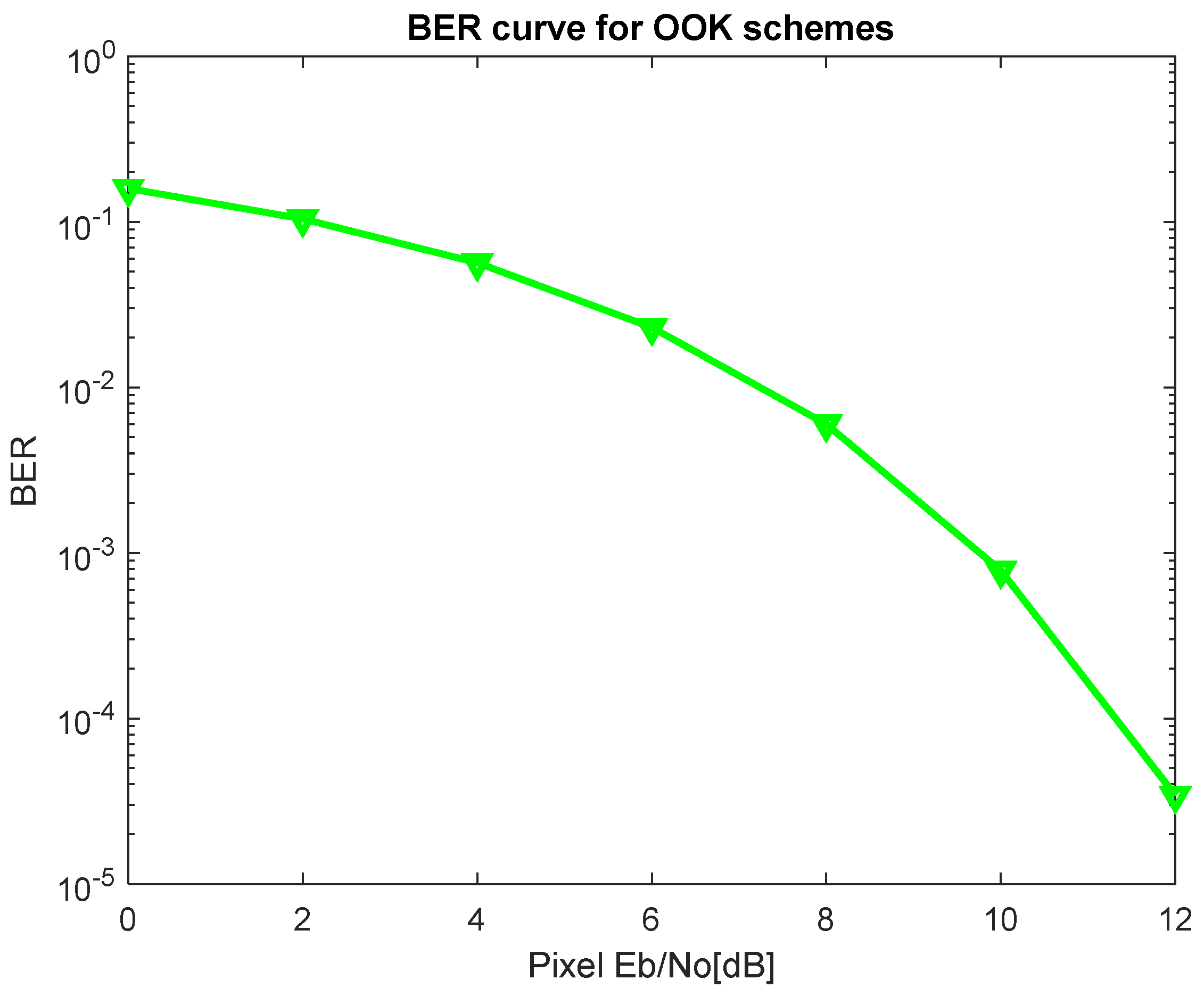
denote the rectangular pulse-shaping function and the symbol period, respectively. Under the assumption that additive white Gaussian noise (AWGN) is the primary channel impairment, the bit error rate (BER), or
, for OOK modulation is estimated by
where
represents the bit energy and
denotes the noise variance. Accordingly, the received signal under AWGN conditions can be characterized based on the transmitted logical state as follows:
Figure 6 shows the bit error rate performance of OOK scheme considering the pixel Eb/N0 as mentioned in Equations (4)–(6).
3.4. Proposed Methodology
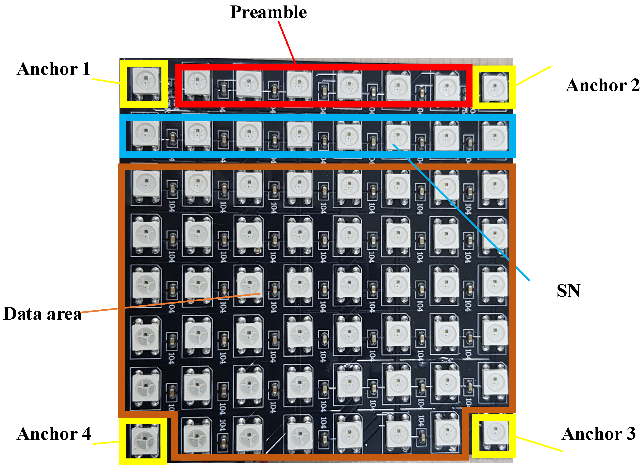
Figure 7 presents the spatial arrangement of the signaling scheme, which incorporates an 8 × 8 LED matrix. Within this structure, the LEDs situated at the four outermost vertices work as reference anchors, ensuring reliable acquisition of spatial coordinates and corner detection. By leveraging the geometric coordinates of these reference points, the receiver applies a perspective transformation to accurately map the LED array and identify the positions of the internal LEDs.
Within this architecture, 46 LED units are dedicated exclusively to data payload transmission. As shown in
Figure 7, this allocation ensures a fixed spatial frame structure, allowing the RoI algorithm to reliably distinguish data-carrying LEDs from the background, even when the camera orientation changes.
The proposed structure includes four anchor LEDs positioned at each corner of the array. In addition, eight LEDs in the SN field are reserved as training signals to provide reference levels for the deep learning-based decoder, enabling more accurate classification of ON and OFF states compared to conventional zero-crossing. A preamble sequence is inserted at the beginning of each frame to enable reliable frame boundary detection. To further enhance signal reliability, a deep learning decoder is applied, improving the SNR and extending the achievable communication distance.
To improve system performance under mobility conditions, the proposed architecture incorporates DL-based algorithms for robust detection and real-time tracking multiple LED arrays. To address the challenges posed by temporal desynchronization and varying frame rates between the transmitter and the receiver, an SN is integrated into each data packet.
The synchronization algorithms should consider for two primary sampling conditions:
Oversampling: When the camera’s frame rate is higher than the transmission rate, SNs enable the receiver to detect and filter out redundant data packets.
Undersampling: In cases where the sampling rate falls below the packet rate, the system utilizes SNs to pinpoint dropped packets and identify discontinuities in the data stream.
The packet rate is determined by the number of transmissions occurring within a specified time interval (e.g., 30 packets/s). Through SN values, the receiver maintains data integrity and accurately reconstructs the original data sequence despite temporal inconsistencies.
3.4.1. Oversampling
Oversampling occurs when the camera’s frame rate is at least twice the transmission frequency of the LED. While this satisfies basic sampling requirements, it causes each packet to be recorded across several consecutive frames, creating redundancies that must be managed during data reconstruction. To address this issue, an SN is included in each data sub-packet (DS), ensuring that all duplicated DSs contain identical payloads and corresponding SN values. By referencing the SN, the receiver can identify and discard redundant packets caused by oversampling. Consequently, only packets with unique, incrementally increasing SN values, for example, n, n + 1, n + 2, are retained and correctly merged to reconstruct the transmitted data stream. By doing that, we can reduce the redundancy packets to merge the payloads.
3.4.2. Undersampling
Undersampling occurs when the frame rate of the camera is insufficient relative to the transmitter’s data rate. In such cases, certain data sub-packets (DSs) are not captured, resulting in discontinuities in the received frame sequence that hinder accurate packet reconstruction. To mitigate this issue, the proposed architecture embeds an SN within each transmitted packet, enabling the receiver to detect and identify missing payloads. For example, if a DS associated with packet n is followed by a packet with an SN n + 2, the receiver identifies packet n + 1 as missing. This comparison of sequential SN values preserves communication integrity despite frame rate mismatches. The system’s ability to detect lost payloads depends on the length of the SN. For instance, a 3-bit SN configuration allows the receiver to track and identify up to seven consecutive missing packets. When non-sequential SN values are detected, the system infers the loss of intermediate data segments, enabling appropriate recovery mechanisms to maintain overall data throughput. By applying the SN, we can detect the missing packets in undersampling cases, and then we can notify the transmitter to send the missing packet again.
3.4.3. Implementation Results
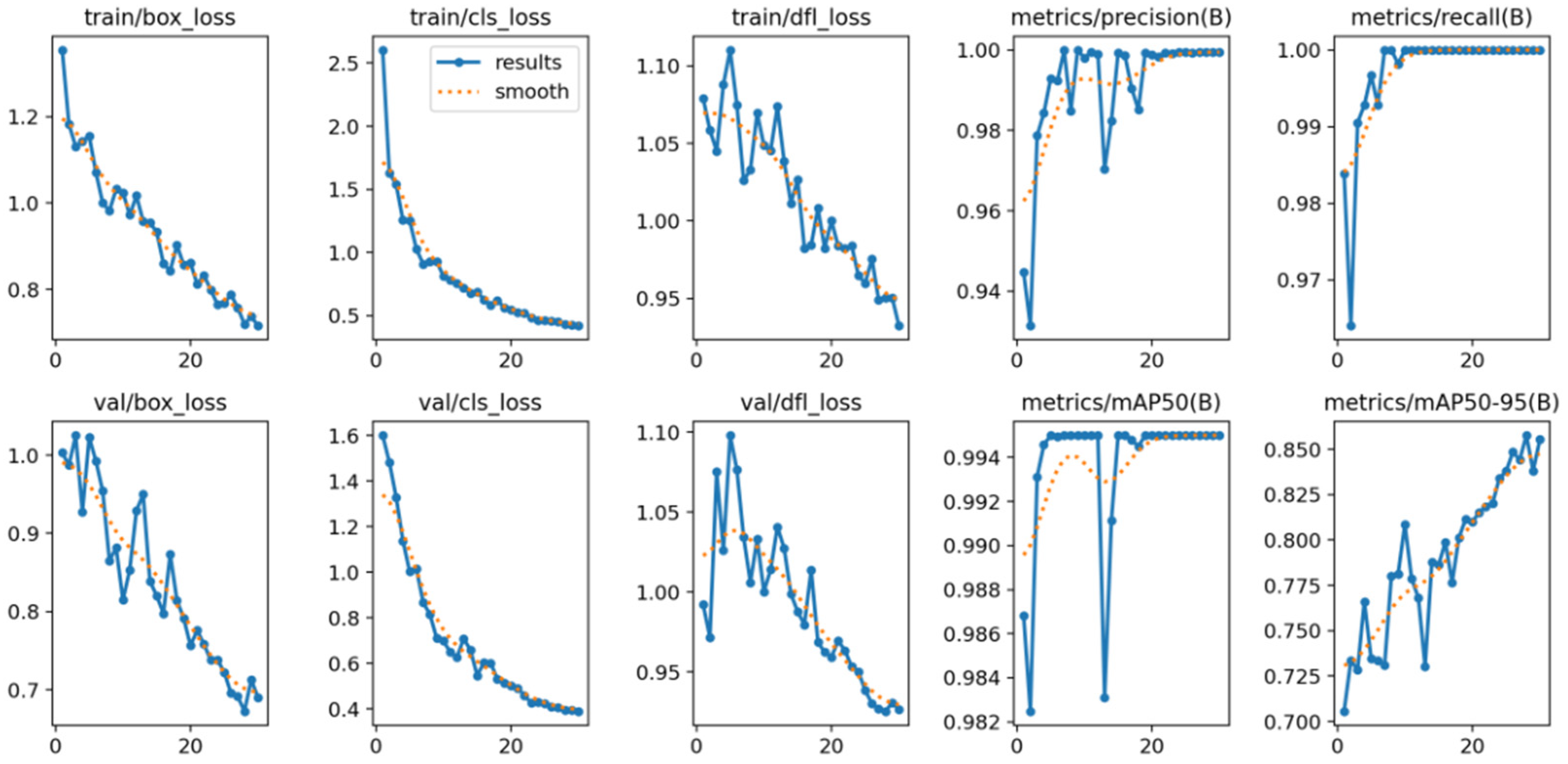
To evaluate the reliability of the proposed system against frame rate fluctuations, the scheme was experimentally validated using various cameras to make sure that this scheme can adapt to any scenario. This combination of hardware platforms enables a comprehensive assessment of communication performance under varying resolutions. This approach ensures a more comprehensive dataset, ultimately leading to better-performing object detection algorithms. The YOLO algorithm is trained on an NVIDIA GeForce RTX 3050 with 30 epochs and it is trained with our dataset. The evaluation results of the training process are illustrated in
Figure 8.
A critical parameter of this architecture is the selection of an SN length. The SN parameters were optimized to ensure reliable synchronization and compatibility between the different frame rates of cameras. This design enables accurate data reconstruction within the asynchronous processing environment, even under nonideal sampling conditions. Using a 16 × 16 LED matrix, the system achieves uncoded data rates of up to 7.68 kbps and coded data rates of up to 5.76 kbps with good BER values. However, with 8 × 8 LED matrix, we only achieve uncoded data rates of up to 1.92 kbps and coded data rates of up to 1.44 kbps. In our work, we demonstrated the 16 × 16 LED matrix at 22 m distance with 20 links simultaneously, with a latency of lower than 30 milliseconds. To achieve longer range, we can use better focal length to improve the communication distance. To achieve good performance under extreme lighting conditions or high ambient noise, we should control camera parameters (exposure time, contracts, brightness, focal length, etc.).
The proposed scheme was implemented and evaluated using multiple camera devices, including a webcam, a CCTV camera and a rolling shutter camera, to investigate the effects of camera frame rate variation. An asynchronous processing incorporates non-synchronous decoding, packet merging, and missing-data detection. The SN length (3 bits) was determined based on the integrated system configuration and operational requirements.
Figure 9 and
Figure 10 illustrate the quantized intensity profiles under varying exposure times and the integrated system configuration, respectively. The experimental setup using a rolling shutter camera (with exposure time of 100 μs, resolution of 1920 × 1080 pixels) is shown in
Figure 10. As shown in
Figure 10, the 20 links LED arrays were allocated in panel with a distance of 10 cm between each LED array. The packet rate is 30 packets per second.
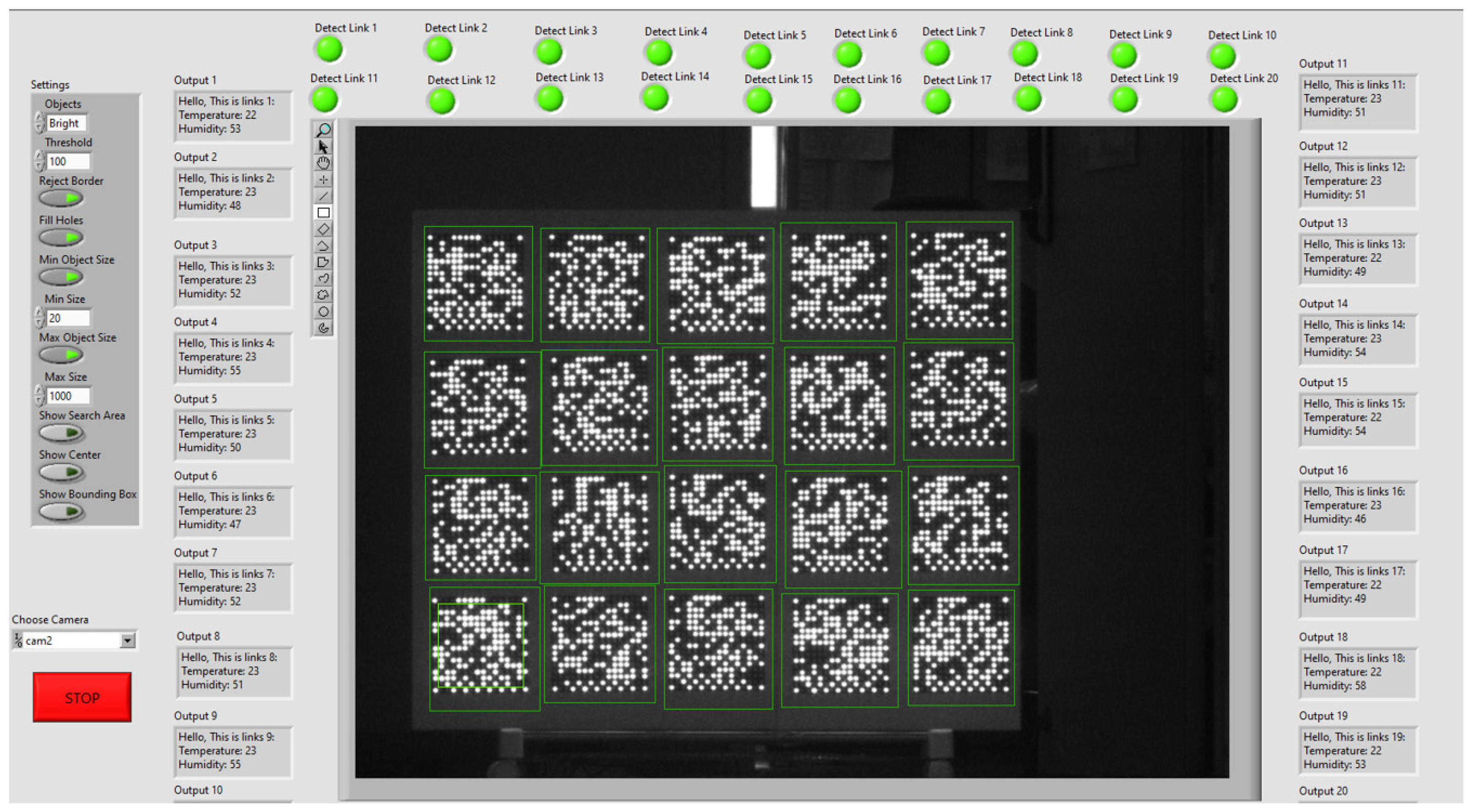
The performance evaluations under various transmission distances are provided in
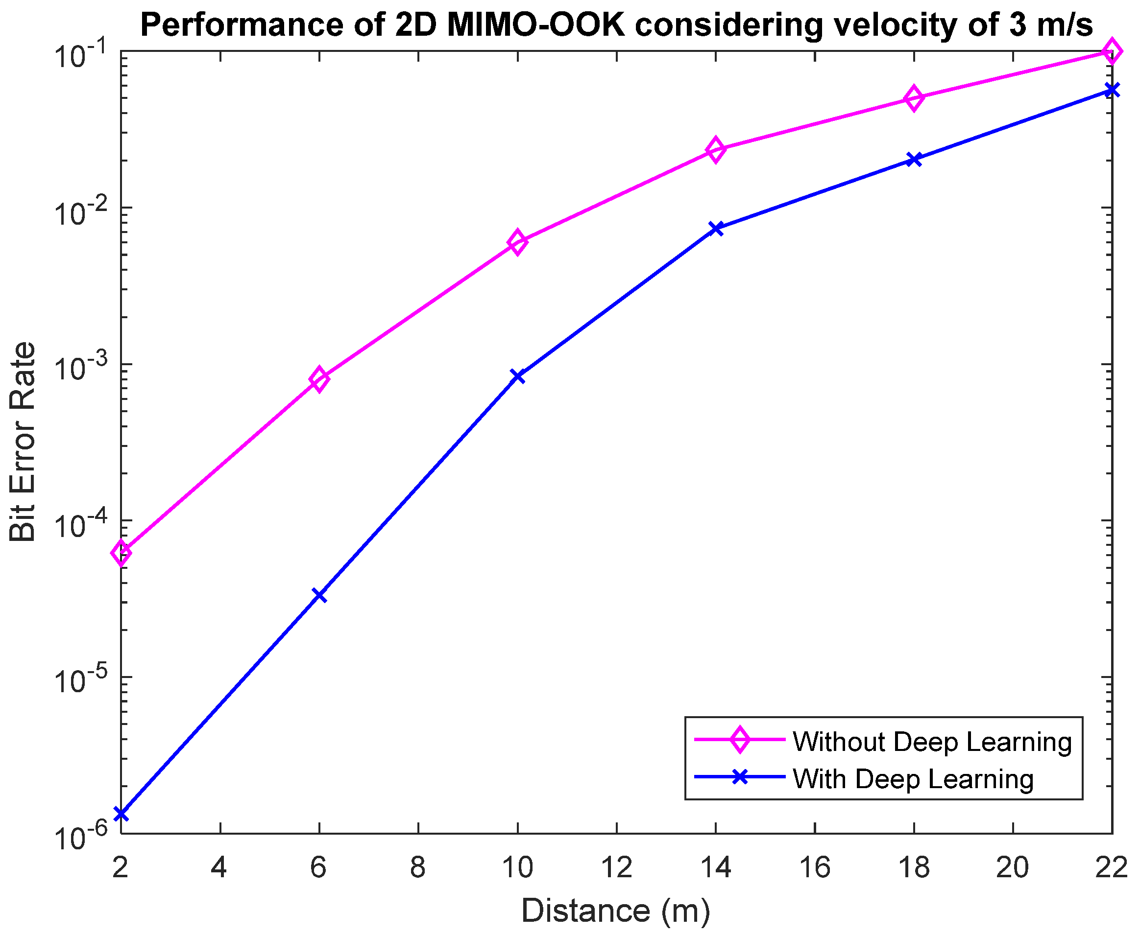
Figure 11 with 20 links. Bit error rate (BER) performance was evaluated three times while maintaining constant transmission distance and noise conditions in
Figure 12. At a distance of 10 m, the proposed deep learning-based decoding method achieved a BER of
, whereas the conventional zeros-crossing approach exhibited inferior performance, with a BER of approximately
, as shown in
Figure 12. The effectiveness of the proposed DL-based decoder in enhancing OCC performance under mobility and long-distance constraints is evident from these results. With long distance, the SNR value is reduced, and the receiver cannot define the threshold between ON status and OFF status of signals. As such, a deep learning decoder is helpful for long range communication. Besides that, YOLOv13 is a good candidate to detect and track objects in mobile environments. Since communication bandwidth is highly dependent on exposure settings, both the duration itself and the critical trade-off between exposure time and noise must be carefully optimized. In addition, the application of channel coding is recommended to further reduce BER or increase the communication range, thereby improving overall system performance. The implementation utilizes a 16 × 16 LED matrix with a smart camera supporting 20 links as well as an 8 × 8 LED matrix paired with a standard webcam supporting 3 links in a mobile environment. The proposed system is capable of operating over distances from 2 to 22 m, as further detailed in the
Supplementary Materials.
4. Conclusions
In this paper, we proposed an optical camera communication (OCC) system, which applies deep learning to light source detection and signal decoder. By applying YOLOv13, our system detects and tracks multiple LED matrixes under mobility conditions in real time, considering long-range environment. The experiments were conducted with two types of cameras (rolling shutter camera and global shutter camera), which make sure that our study is applicable for any camera, demonstrating high-speed OCC with low-cost hardware. In addition, the proposed asynchronous algorithm, based on sequence numbering for packet merging and missing packet detection, effectively addresses frame rate variation. Experimental results show that the system achieves good performance, supporting multi-links over up to 22 m of distance, thus making it suitable for multi-user IoT scenarios.