1. Introduction
The ship’s steering system is a core component for ensuring navigational safety and manoeuvrability; its dynamic response and control accuracy directly influence the vessel’s collision-avoidance capabilities and navigational economy in complex sea conditions [
1]. As the global shipping industry evolves towards greater environmental sustainability, intelligence and high reliability, traditional steering actuation technologies are no longer sufficient to meet the energy efficiency and safety requirements of modern ocean-going vessels. Consequently, the development of a new generation of highly efficient and reliable steering actuation systems has become an urgent priority within the field of marine engineering.
Throughout the development of marine actuation technology, three distinct technical approaches have emerged: valve-controlled hydraulic rudders, electro-mechanical actuators (EMAs) and electro-hydrostatic actuators (EHAs). Their evolution essentially represents a continuous optimisation of the balance between power density, transmission efficiency and reliability.
Valve-controlled hydraulic steering gear has long dominated steering systems on large vessels due to its high power density, strong output force and outstanding shock resistance [
2]. However, their operating principle, which relies on throttle valves to regulate flow, results in a significant dissipation of energy in the form of heat, with system efficiency generally below 50%; complex hydraulic piping not only increases the risk of leakage but also imposes stringent requirements on oil cleanliness, leading to persistently high maintenance costs throughout the entire lifecycle [
3,
4].
To address the inherent shortcomings of hydraulic systems, the EMA employs a purely mechanical transmission architecture comprising a ‘motor–gearbox–ball screw’, fundamentally eliminating hydraulic components. It offers significant advantages such as high transmission efficiency, the absence of hydraulic leakage and a compact structure, and has already been successfully applied in small vessels and auxiliary actuation systems [
5]. However, constrained by the load-bearing capacity of the reducer and ball screw, the EMA has a relatively low power density, making it difficult to meet the high output force and torque requirements of large-vessel steering systems; mechanical transmission components are prone to fatigue failure under wave impact loads and lack sufficient impact resistance; more critically, should the ball screw or gears become jammed, this would directly result in steering failure, posing a serious threat to navigational safety [
6,
7]. These shortcomings mean that EMA systems are not yet suitable for the high-load, high-reliability operating conditions of large ocean-going vessels.
As a new type of pump-controlled electro-hydraulic servo system, EHA employs an integrated closed-loop ‘motor–pump–cylinder’ architecture, combining the dual advantages of hydraulic transmission and electric drive, and thus offers a novel solution to the contradictions inherent in traditional technical approaches [
8]. It retains the characteristics of hydraulic systems—such as high power density, strong shock resistance and the absence of mechanical jamming risks—whilst eliminating the throttling losses of valve-controlled systems through direct motor-controlled flow regulation, thereby increasing system efficiency to over 80%. At the same time, EHA offers multiple advantages, including strong resistance to contamination, high integration, modular design and ease of maintenance, and has become a core technological direction for the upgrading of marine engineering and ship actuation systems [
9]. At the industrial application level, leading international companies such as Bosch Rexroth and Parker Hannifin have launched series of marine EHA products, which are widely used in container ships, oil tankers and naval vessels [
10,
11]. In terms of academic research, significant progress has been made in recent years regarding the integrated design, energy recovery and thermal management of EHA systems, further advancing their practical implementation in marine engineering [
12,
13].
Although EHA offers significant advantages, its application in ship steering systems still faces severe challenges posed by complex nonlinearity and strong disturbance coupling, with three key bottlenecks hindering its large-scale deployment. Firstly, wave impacts and time-varying parameters under complex sea conditions reduce system robustness, resulting in insufficient stability during low-speed operation, which makes it difficult to meet the requirements for precise ship steering [
14]. Secondly, the system’s adaptability to wide voltage inputs and its dynamic response capabilities still need to be improved to match the voltage fluctuation characteristics of the ship’s electrical system, which can range from ±20% to even wider [
15]. Thirdly, system integration needs to be strengthened; existing EHA systems predominantly employ a discrete design comprising separate motors, pumps and valves, resulting in large size and weight, making them ill-suited to the confined installation spaces on ships [
16].
To overcome these bottlenecks, researchers have conducted extensive studies on position tracking and robust control for EHA systems. In terms of control strategies, various advanced methods have been proposed, including adaptive robust control [
17,
18], sliding mode control [
19,
20], extended state observers [
21,
22], and active disturbance rejection control (ADRC) [
23] which have to some extent improved the system’s tracking accuracy and robustness. However, when applied to practical marine engineering scenarios, existing strategies still exhibit significant limitations; a traditional PID control features a simple structure but exhibits extremely poor robustness under typical marine disturbances such as random wave loads and fluctuations in the ship’s power grid voltage, making it difficult to suppress EHA parameter perturbations and mismatch disturbances [
24]. Although single-sliding-mode control possesses a certain degree of disturbance rejection capability, it has not been optimised for marine salt spray and vibration conditions, resulting in high-frequency oscillations, insufficient long-term operational reliability, and a lack of adaptation to wide voltage input characteristics; adaptive robust control can compensate for parameter changes online, but suffers from poor real-time performance under sudden wave load changes, high algorithmic complexity, and difficulties in engineering deployment [
17]. Expanded state observers can compensate for composite disturbances, but their ability to suppress mismatched disturbances in marine environments is limited, and their low-speed stability is poor [
21]. Neural network adaptive control has strong nonlinear approximation capabilities but is prone to overfitting under conditions of long-term continuous ship operation and complex disturbance coupling, making it difficult to meet the high reliability requirements of steering systems [
22].
Regarding mismatched disturbances, robust adaptive sliding mode control incorporating an extended state observer [
25,
26] and fast terminal sliding mode control based on a disturbance observer [
27] have demonstrated potential in suppressing wave loads; however, these have not yet been systematically integrated to address wide voltage fluctuations in ships. For non-smooth nonlinearities such as dead zones and saturation, adaptive dynamic surface control methods [
28] provide a theoretical framework, but practical validation in marine EHA remains insufficient. Although composite strategies integrating disturbance observation and sliding mode control have attracted attention, there is still a lack of systematic design tailored to wide voltage fluctuations on ships and the harsh engine room environment [
19]. In recent years, some researchers have begun to explore model predictive control [
13,
29] and event-triggered mechanisms [
30,
31] to balance control performance with computational burden. Among these, event-triggered neural adaptive control and variable-sampling model predictive control offer new directions for EHA control from the perspectives of reducing communication load and improving energy efficiency, respectively; however, mature solutions have yet to be established for marine EHAs. Furthermore, new methods such as perceptual control design for EHA health management and remaining life optimisation [
29], as well as finite-time command filtering backstepping control, offer valuable avenues for enhancing the dynamic performance and long-term reliability of marine EHA systems in marine environments; however, these still require validation under actual ship operating conditions.
From a broader perspective of fluid power transmission technology, research findings in the fields of hydraulics and pneumatics can provide cross-disciplinary theoretical references for the design of marine EHA control. In the field of hydraulic transmission, given the strong nonlinearity and time-varying parameters of hydraulic cylinders, adaptive robust speed control strategies can effectively suppress load disturbances, improving low-speed smoothness and dynamic response accuracy [
32]; for multi-actuator synchronisation control scenarios, deviation-coupled control and sliding-mode synchronisation algorithms can effectively resolve synchronisation errors caused by load imbalance and parameter variations, providing valuable insights for the design of multi-cylinder coordinated steering drives [
33].
In research into the dynamic behaviour of actuator systems, the electro–hydraulic coupled dynamic model has revealed the mechanisms by which orifice throttling, fluid compressibility and friction nonlinearity influence the system’s dynamic response, laying the theoretical foundation for optimising the dynamic characteristics of electro-hydrostatic actuators [
34]. Regarding the reliability and degradation of hydraulic actuators, research into failure mechanisms—such as seal wear, fluid leakage and mechanical fatigue—along with life prediction and health management techniques, has provided an engineering basis for the design of high-reliability actuators [
35].
In the field of pneumatic transmission, when addressing the inherent characteristics of pneumatic systems—namely high compressibility and low damping—model-based nonlinear predictive control and adaptive backstepping control methods can significantly mitigate low-speed crawling in cylinders and improve speed tracking accuracy [
36,
37]. Cross-coupled control and fuzzy sliding mode control strategies for pneumatic synchronisation systems have effectively resolved issues such as low synchronisation accuracy and poor disturbance rejection caused by gas compressibility; the design philosophy can be directly applied to multi-EHA cooperative steering systems [
38,
39]. The gas–solid coupled dynamic model elucidates the intrinsic relationship between gas flow characteristics, valve orifice characteristics and actuator dynamic response, providing a methodological reference for flow matching and dynamic optimisation of EHA systems [
40]. The wear mechanisms of pneumatic valves, the ageing patterns of seals and fault diagnosis techniques provide a technical pathway for the service life assessment and health management of key hydraulic components in EHA systems [
41,
42]. These common technological breakthroughs have further refined the theoretical framework for actuator system design and provided crucial support for addressing key challenges in marine EHA systems, such as nonlinear control, dynamic stability and long-term reliability optimisation.
In summary, existing marine EHA control strategies share a common research gap; they have not been customised to address the random wave disturbances, wide voltage fluctuations and harsh engine room environments specific to ocean-going vessel steering. Most methods either focus solely on suppressing a single type of disturbance or employ algorithms that are too complex for practical implementation; consequently, they generally fail to simultaneously meet the core requirements of strong robustness, rapid response, high precision and ease of engineering. This creates an urgent need for a novel control architecture that is tailored to ship steering conditions, features a simple structure, and can comprehensively address multi-source disturbances.
To address this research gap, this paper, with the high-load steering requirements of large ocean-going vessels as its ultimate application objective, innovatively proposes an integrated drive-control architecture and constructs a dual-loop composite control strategy combining outer-loop sliding mode control with inner-loop motor PID control, specifically tailored for marine steering conditions. The main contributions of this paper are reflected in the following three aspects: Firstly, a fifth-order mechatronic–hydraulic coupled dynamic model comprising a permanent magnet synchronous motor, hydraulic pump, hydraulic cylinder and load is established. This model accurately describes the system’s nonlinearity and multi-physics coupling characteristics, providing a reliable theoretical foundation for control algorithm design. Second, a ‘double-loop composite control strategy’ comprising ‘outer-loop sliding mode control + inner-loop PID’ is proposed. Relying on the strong robustness of sliding mode control, this strategy precisely suppresses random wave loads and hydraulic nonlinear disturbances, whilst the inner-loop PID ensures rapid motor response and steady-state accuracy. It simultaneously adapts to the wide voltage fluctuation characteristics of vessels, resulting in comprehensive performance that is significantly superior to traditional single-control methods under complex marine disturbances. Thirdly, we have completed the design of an integrated drive-control structure and developed a three-phase full-bridge inverter main circuit capable of handling wide voltage inputs. This enhances system integration and adaptability to the marine environment, resolving the issues of large size and low reliability associated with traditional discrete designs.
Based on the above research approach, this paper first establishes a mechatronic–hydraulic coupled dynamic model of the EHA system; secondly, it designs an integrated drive-control composite control architecture and completes parameter tuning; on this basis, system hardware integration and simulation verification are carried out. Finally, proof of concept was achieved through phased bench testing, focusing on the effectiveness of the system’s core principles and control strategies. Subsequent work will build upon these research findings to extend the system’s applicability to high-load operating conditions on large vessels, thereby providing technical support for the wider adoption of marine EHA technology in the shipping sector.
2. Structure and Operating Principles of EHA
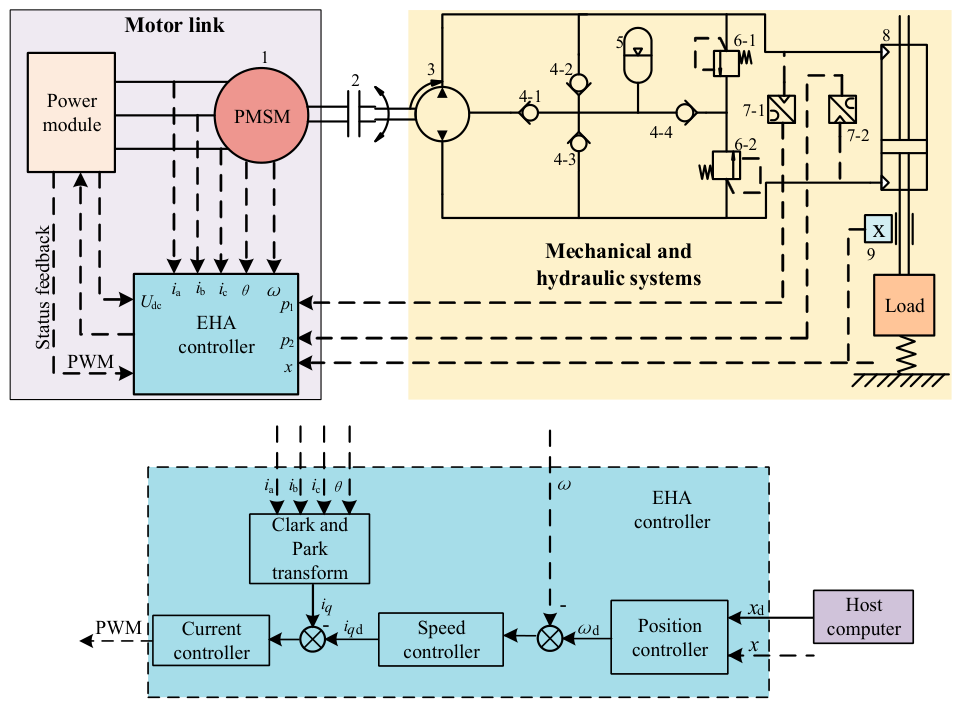
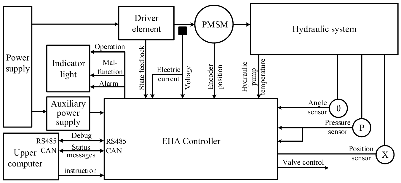
EHA is an integrated actuator that combines electric drive, hydraulic transmission and intelligent control. It utilises power-to-motion conversion and volumetric speed regulation principles to achieve power transmission and control; its basic structural framework is shown in
Figure 1.
As can be seen from the diagram, the system can be divided into two main functional modules: drive control and hydraulic actuation. The drive control module comprises the controller, power supply module, permanent magnet synchronous motor (PMSM), and signal acquisition components such as a rotary transformer and current sensors; the hydraulic actuation module consists primarily of a hydraulic pump, hydraulic cylinder, check valve, accumulator and relief safety valve.
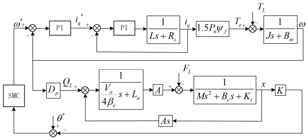
The basic operating principle of the system is as follows: The host computer issues a target rudder angle command, which, together with the actual piston displacement of the hydraulic cylinder (converted to rudder angle) fed back by the displacement sensor, is input into the position controller. After processing by the position controller, a target motor speed command is output; the difference between the target speed and the actual motor speed fed back by the rotary transformer is calculated by the speed controller, which then outputs a target current command for the q-axis. The actual phase current of the motor, as fed back by the current sensor, is converted to the actual q-axis current via the Clark and Park transformations. The difference between this and the target current output by the speed controller is calculated by the current controller to generate a PWM drive signal, which controls the three-phase inverter to output AC power to drive the PMSM.
The PMSM drives the hydraulic pump via a coupling, and outputs pressurised oil at the corresponding flow rate and direction. The pressurised oil enters the two chambers of the hydraulic cylinder, creating a pressure differential that pushes the piston to drive the rudder blade and complete the deflection. By adjusting the motor’s speed and direction in real time, the displacement, speed and output force of the hydraulic cylinder can be precisely controlled, ultimately achieving efficient conversion of electrical energy into hydraulic energy and mechanical energy, as well as high-precision servo control of the rudder angle.
3. System Mathematical Model
3.1. Model Assumptions and Rationality Analysis
Mathematical modelling serves as the core foundation for analysing the dynamic characteristics and designing control strategies of EHA systems. To reduce model complexity and highlight the dominant dynamic behaviour while maintaining sufficient accuracy in describing the core physical characteristics, and in accordance with the experimental conditions and research focus of the ship steering EHA system in this paper, the following three reasonable simplifying assumptions are proposed, and their validity is demonstrated.
First, the steady-state flow deviation caused by internal and external oil leakage of the actuator is ignored.
Second, the frictional pressure loss and local pressure loss in the hydraulic pipelines are ignored.
Third, the average volumetric deviation caused by oil compression during conventional steady-state operation is ignored.
Regarding the assumption of ignoring steady-state leakage flow deviation, the servo hydraulic cylinder used in the experiments of this study adopts a combined sealing structure of a Glyd ring and an O-ring, and the hydraulic pump employs a port plate clearance compensation design. According to preliminary test data, under the maximum operating pressure of the system, the internal leakage of the hydraulic cylinder and the hydraulic pump is extremely low, and the external leakage is almost nonexistent. The total steady-state leakage flow of both is far smaller than the main operating flow of the system, and its influence on core parameters such as the average piston velocity of the hydraulic cylinder and the steady-state rudder angle accuracy can be neglected.
Regarding the assumption of ignoring frictional pressure loss and local pressure loss in the hydraulic pipelines, the EHA system designed in this paper adopts an integrated drive and control design, which greatly shortens the length of the hydraulic pipelines. Moreover, the pipeline layout is simple, without unnecessary bends and fittings. According to the formula for frictional pressure loss in fluid mechanics, the pipeline pressure loss is positively correlated with the pipeline length and negatively correlated with the pipeline diameter, and it is also influenced by the fluid velocity inside the pipe. Within the normal operating flow range of the system, the oil velocity in the pipelines remains at a reasonable level, resulting in extremely low frictional pressure loss and local pressure loss. The sum of these two types of pressure loss is far smaller than the system operating pressure, and their influence on the pressure difference between the two chambers of the hydraulic cylinder and the output force is negligible, causing no significant interference to the core performance of the system. Therefore, the assumption of ignoring the frictional pressure loss and local pressure loss in the hydraulic pipelines is valid.
Regarding the assumption of ignoring the steady-state average oil volumetric deviation, according to the basic law of oil compression, when the pressure is stable, the fixed volume change caused by oil compression is proportional to the initial volume of a single chamber of the hydraulic cylinder and the operating pressure variation, and inversely proportional to the effective bulk modulus of the hydraulic oil. Under the maximum operating pressure condition of the system in this study, the steady-state volume change caused by oil compression is a negligible minor error.
This study focuses on the medium-speed dynamic response and low-speed steady-state control of the ship steering system. Under such operating conditions with stable pressure, the effect of the aforementioned minor fixed volumetric deviation on the steady-state accuracy of the rudder angle is negligible. It should be specifically noted that the dynamic elastic effect of the oil is retained in the model to accurately describe the dynamic stiffness characteristics of the system; only the fixed volumetric deviation under steady state is ignored. Only in extreme dynamic conditions such as rapid acceleration and rapid deceleration will the volumetric hysteresis effect caused by oil compression have a noticeable impact, and such conditions are not the core focus of this study. Therefore, the above assumption is valid.
It should be clarified that the above simplifying assumptions have well-defined applicability boundaries; they are only valid for conditions of medium-to-low pressure, short pipelines, medium dynamic response, and well-sealed conditions. If subsequent research is extended to high-pressure, high-speed, long-pipeline, seal aging, or extreme dynamic conditions, it will be necessary to introduce the nonlinear characteristics of leakage flow and pipeline pressure loss formulas, and further consider the influence of dissolved air in the oil on the effective bulk modulus, so as to improve the global adaptability of the model.
3.2. Mathematical Model of the Permanent Magnet Synchronous Motor
A surface-mounted PMSM has been adopted as the driving core. The inductances of the d-axis and q-axis are equal (
). The voltage equation, electromagnetic torque equation and mechanical motion equation in the synchronous rotating d–q coordinate system are respectively:
In the formula, and are the voltages on the d and q axes (V); is the stator phase resistance (Ω); and are the currents on the d and q axes (A); is the electrical angular velocity (rad/s); is the rotor permanent magnet flux linkage (Wb); is the electromagnetic torque (N·m); is the number of motor poles; is the motor rotational inertia (kg·m2); is the load torque (N·m); is the motor mechanical angular velocity (rad/s); and is the motor viscous friction coefficient (N·m·s/rad).
Adopting the vector control strategy with
eliminates the d-axis current component. Combining the above equations yields the simplified state equation of the motor loop:
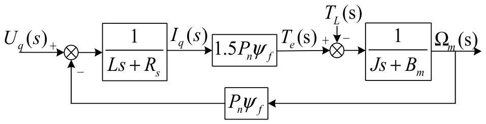
By performing Laplace transforms on the three Equations (1)–(3), we can obtain
From this, the dynamic block diagram of the servo motor can be obtained as shown in
Figure 2:
3.3. Mathematical Model of the Machine–Hydraulic Circulation Section
The equation for the hydraulic pump’s output/input flow is as follows, with the volume changes of the hydraulic oil and the pressure losses in the pipeline being ignored:
In the formula, represents the displacement of the hydraulic pump (m3/rad); , , and are the pressures at the outlet, inlet, and oil discharge port of the hydraulic pump (Pa); and and are the internal and external leakage coefficients of the hydraulic pump (m3/(s·Pa)).
Assuming the hydraulic pump and hydraulic cylinder are well sealed and ignoring oil loss from the accumulator and oil outlet, the hydraulic pump’s output flow is equal to the hydraulic cylinder’s input flow, which is equal to its output flow. The continuity equation for the flow of the symmetrical hydraulic cylinder is
In the formula, represents the effective area of the hydraulic cylinder piston (m2); represents the piston displacement (m); represents the initial volume of the single chamber of the hydraulic cylinder (m3); represents the elastic modulus of the oil (N/m2); represents the leakage coefficient of the hydraulic cylinder piston (m3/(s·Pa)); and and represent the inlet and return oil chamber pressures of the hydraulic cylinder (Pa).
Assuming
, let the total leakage coefficient of the system be
. For the symmetrical hydraulic cylinder,
. Solving the simultaneous Equations (6) and (7) yields the flow equation of the mechanical–hydraulic link:
In the formula, represents the load flow rate, and represents the pressure difference between the two chambers of the hydraulic cylinder (Pa).
It should be additionally noted that a closed hydraulic circuit architecture is employed for the hydraulic cylinder in this work, where and denote the absolute pressures in the cap-end chamber and the rod-end chamber of the cylinder, respectively. These absolute pressures remain positive under all operating conditions. represents the pressure difference between the two cylinder chambers, and its sign directly corresponds to the direction of motion of the hydraulic cylinder; when , the pressures in the two chambers are balanced, the piston is stationary, and the rudder angle is maintained at a steady state; when or , it indicates the respective direction of the piston movement and the associated positive or negative deflection of the rudder angle.
The mechanical equilibrium equation of the hydraulic cylinder piston is as follows:
In the formula: represents the total mass of the load (kg); is the viscous friction coefficient of the hydraulic cylinder (N·s/m); is the stiffness of the elastic load (N/m); is the external load force (N).
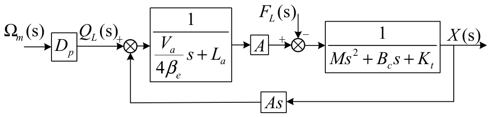
Taking the Laplace transform of Equations (8) and (9) yields:
From this, the dynamic block diagram of the hydraulic system is shown in
Figure 3:
3.4. State Equation of Mechanical–Electrical Coupling
Select the system’s state variables
. Combining the mathematical models of the motor and machine-fluid section yields the complete fifth-order electromechanical–hydraulic coupling state equation of the EHA system:
In the equation, represents the system friction torque (N·m). It provides a precise mathematical model for the subsequent controller design by comprehensively describing the coupling characteristics of the electrical, mechanical and hydraulic multi-physics fields in the EHA system.
4. EHA System Design
4.1. Design of the Integrated Control Architecture for Drives and Controls
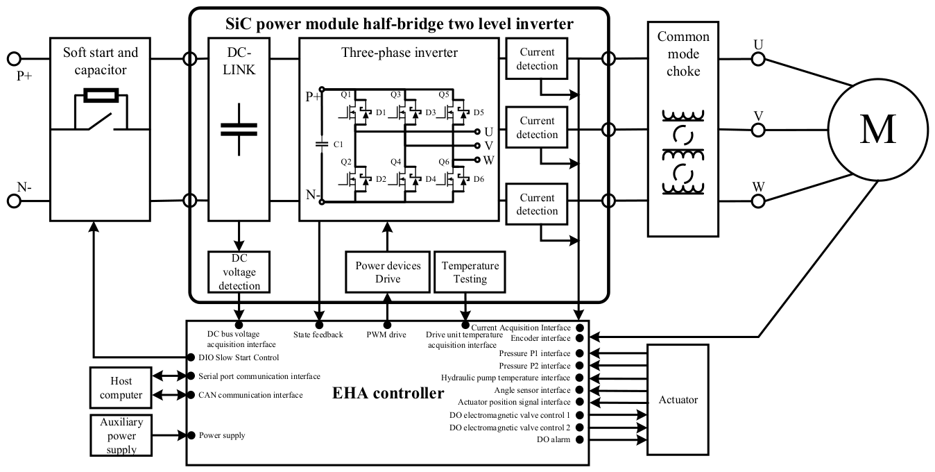
Figure 4 shows the electrical structure diagram. The system abandons the traditional ‘separate controller + separate driver’ split design. Instead, it integrates the control and power drive units into a single sealed box to form a complete drive-control integrated device. The control and drive boards communicate directly via an internal high-speed bus, eliminating the need for external control cables and significantly improving the signal transmission rate. The drive module’s current, voltage and temperature sampling signals are sent directly to the ADC interface of the main control board without the need for an additional signal conversion unit. The main control board then outputs the SVPWM drive signal directly to the SiC power module, achieving precise motor speed and torque control.
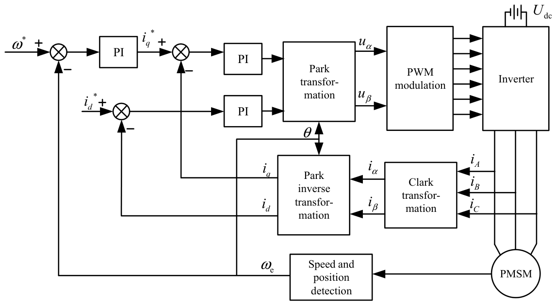
As demonstrated in
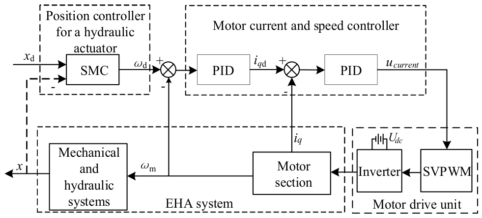
Figure 5, the system employs a three-closed-loop control architecture, incorporating an external loop position sliding mode control and an internal loop motor PID dual-loop control. The current loop is the innermost loop. The core function of the system is to rapidly track the Q-axis current command, suppress current fluctuations and grid disturbances, ensure the linearity and stability of the motor torque output, and provide a foundation for the system’s rapid response. The loop in question is the so-called ‘speed loop’. The target speed output from the position loop is used as the command, with the actual motor speed serving as the feedback. It has been demonstrated that this leads to an enhancement of the system’s speed response characteristics and anti-load disturbance ability. Furthermore, it is imperative to ensure that the control accuracy and response speed of the rudder speed meet the stipulated design requirements. The position loop is the outermost loop. The target rudder angle issued by the upper computer is accepted as the command. Furthermore, the rudder angle is converted from the actual displacement of the hydraulic cylinder, thus serving as the feedback mechanism. The primary function of this apparatus is to rectify the nonlinear and non-matching disturbance problems that are prevalent in machine–hydraulic links. Furthermore, it guarantees that the system’s rudder angle tracking accuracy aligns with the stipulated design criteria, ensuring steady-state precision.
The system’s architecture comprises three loops, the purpose of which is to ensure both a rapid dynamic response speed and anti-interference capability. This is achieved through the inner loop, while the outer loop guarantees steady-state control accuracy. The system has the capacity to evaluate the rapidity, accuracy and robustness of the EHA system, thereby ensuring that it fulfils the performance index requirements of the ship’s steering system.
4.2. Design of the Sliding Mode Controller for the Mechanical–Hydraulic System
The mechanical–hydraulic link of the EHA system is a third-order nonlinear system with parameter uncertainties and external load mismatch disturbances. It is evident that traditional PID control systems are not adequately equipped to satisfy the stringent demands of high-precision position control. Sliding mode control has been demonstrated to demonstrate a high degree of resilience to both parameter disturbances and external load interference. It is therefore evident that a sliding mode controller is meticulously designed for the position loop.
Coordinate transformation is performed on the mechanical–hydraulic link, and the state variables are redefined as
. The state equation of the transformed mechanical–hydraulic link then becomes
In the formula,
represents the control input. The remaining parameters are expressed as
Let the system’s reference position signal be
, and define the position error and its derivatives of each order:
The linear sliding surface is to be designed:
Use exponential convergence
(
); the sliding mode control law is derived as follows:
The parameters of the sliding surface and the convergence law are determined using the Lyapunov stability criterion in conjunction with pole placement and simulation-based iterative tuning, a method widely adopted in the control design of electro-hydrostatic actuators. For a third-order position tracking system, the sliding surface is defined by Equation (12). The characteristic equation of the sliding surface is
To achieve a fast and oscillation-free response, the closed-loop pole was selected as , , yielding the initial values and . The parameters of the tracking law are subject to Lyapunov stability conditions, requiring ,. To account for chaffing suppression in the hydraulic system, the parameter range is set to , . Finally, the parameters are fine-tuned through iterative simulation under typical operating conditions, with the aim of achieving minimal steady-state error, negligible chaffing, and rapid dynamic response. The optimal parameters ultimately determined are , , , and .
4.3. Design of the PID Controller for the Motor Section
The structural parameters of the motor section exhibit minimal variation in response to operating conditions, and can be approximated as a linear system. The utilisation of PI control has been demonstrated to yield optimal dynamic and static performance outcomes. Consequently, both the speed loop and the current loop are configured with PI controllers. The control law is as follows:
In the formula, and represent the output of the speed loop and the current loop, respectively. The parameters and are the PI parameters of the speed loop, while and are the PI parameters of the current loop. The parameters and represent the target rotational speed of the motor and the actual rotational speed, respectively. The parameters and represent the target current on the q-axis and the actual current, respectively. The parameters and represent the PI parameters of the current loop.
The parameters of the current loop and speed loop were tuned using the Ziegler–Nichols (Z–N) critical ratio method, incorporating modifications specific to hydraulic systems; this is a well-established strategy for motor-driven hydraulic servo systems. For the current loop, the speed loop was disconnected and a step current command was applied. The proportional gain was increased until sustained oscillation occurred, thereby determining the critical gain
and critical period
s. The initial PI parameters are calculated as follows:
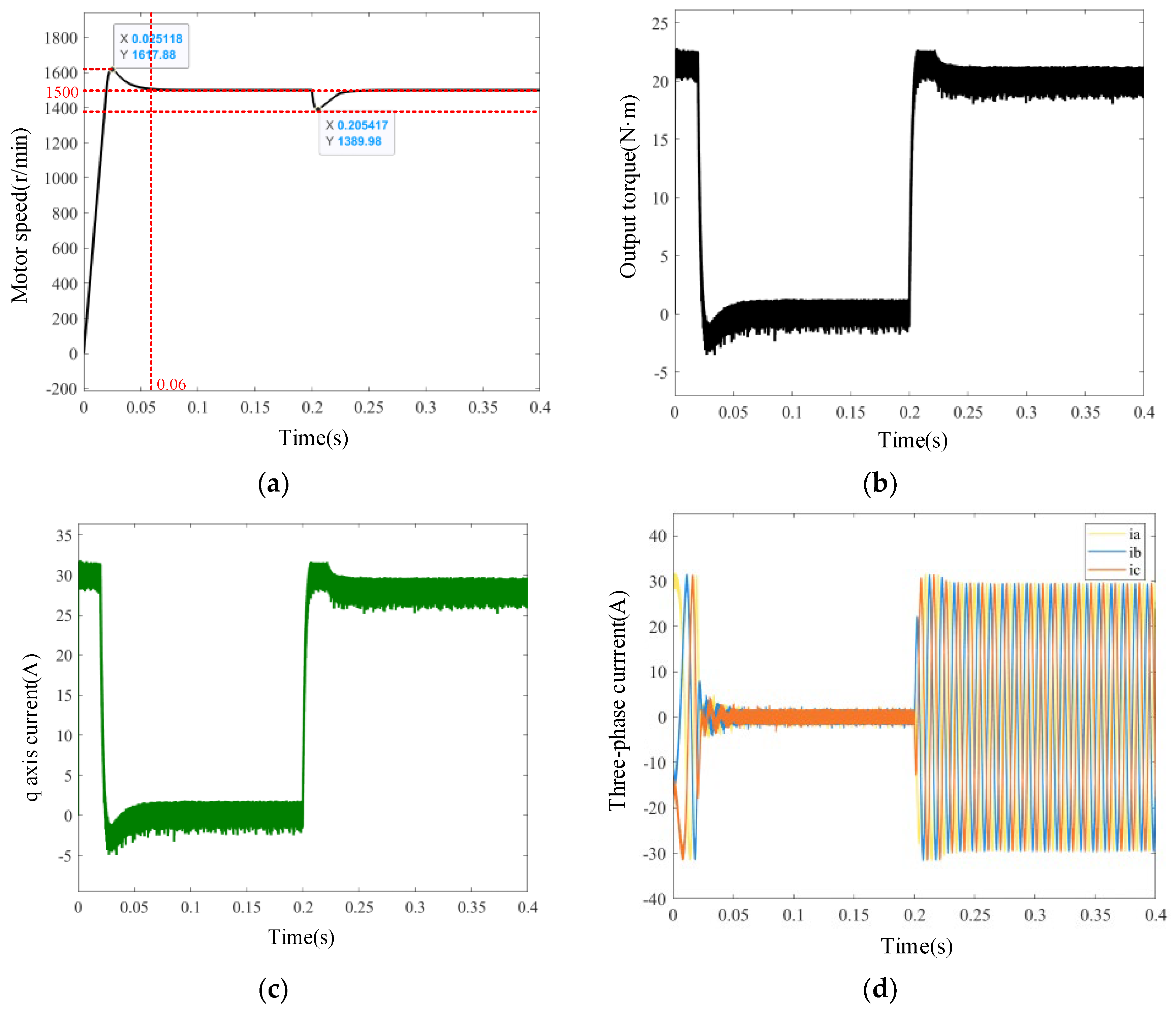
Initial values: ,. Following EHA disturbance correction for the vessel, the final parameters were , . For the speed loop, the current loop was closed, and the Z–N test was repeated under a step speed command, yielding , s. The initial parameters were , . Following low-speed smoothness correction of the ship’s servomotor, the final parameters were , . The tuning parameters were verified through simulations under no-load, 10 N·m and 20 N·m load conditions to determine the system’s fast response capability and disturbance rejection performance.
4.4. Design of the System’s Main Circuit Topology
In order to enhance the wide voltage input adaptability and dynamic response capability of the EHA system, the main circuit of the system adopts a voltage-type three-phase full-bridge inverter topology. The overall topology structure is illustrated in
Figure 6.
The main circuit can be divided into three parts in general: the input side, the power conversion side, and the output side. The specific design ideas for each module are as follows.
Input side module: This side is sequentially equipped with EMI filter, soft-start circuit and DC filter capacitor. The EMI filter’s function is to suppress the conducted interference on the DC bus, enabling the equipment to pass the ship electromagnetic compatibility test; the soft-start circuit mainly prevents excessive current during power-on, preventing the power devices from being burned out; the DC filter capacitor’s role is to stabilize the bus voltage and weaken the voltage spikes during the switching process.
Power conversion side module: The core selection of power conversion includes the EBS-D7-015-T4B-F01 power module of the three-phase full-bridge inverter circuit, which converts DC electricity into three-phase AC electricity to supply the motor. Additionally, it is equipped with a braking circuit and an external braking resistor to consume the energy that the motor pumps back to the bus when decelerating or stopping, preventing the system from being affected when the rudder speed changes abruptly.
Output side module: The output end is successively connected with LC filter and common mode inductor. The LC filter is used to filter out the high-frequency harmonic components in the inverter’s PWM waveform, reducing the torque pulsation and copper loss and iron loss of the motor; the common mode inductor is used to eliminate the common mode interference on the output side, preventing the interference from being transmitted to the sensors and control board and affecting the sampling accuracy.
7. Conclusions
Addressing the high-load steering requirements of large ocean-going vessels, this paper systematically investigates the design, modelling, control, and experimental validation of an electro-hydrostatic actuator for ship steering, thereby establishing a comprehensive technical framework that spans theoretical modelling, control strategy design, hardware integration, and experimental verification.
In terms of theoretical modelling, a fifth-order electro–hydraulic–mechanical coupled state-space model is derived, which fully captures the system’s nonlinear characteristics by comprehensively integrating the dynamics of the permanent magnet synchronous motor, the flow continuity of the hydraulic pump, and the force balance of the hydraulic cylinder. The validity of the simplifying assumptions in the mathematical model is quantitatively analysed. Preliminary experimental data confirm the feasibility of neglecting actuator leakage; fluid dynamics calculations demonstrate the justifiability of ignoring pipeline pressure losses; and an analysis of the compressible volume change of the hydraulic fluid clarifies the conditions under which steady-state fluid compression effects can be neglected. The combined error introduced by these three simplifications is no greater than 3%, which has a negligible impact on the validity of the core conclusions. Moreover, the applicability boundaries of the simplified model are explicitly stated, providing a foundation for future model extensions.
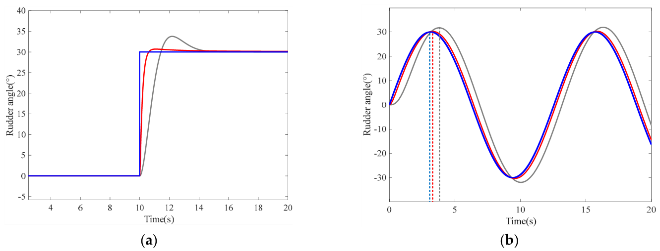
In the domain of control strategy design, a triple-loop composite control architecture is established, comprising ‘outer-loop position sliding mode control + inner-loop motor PID dual-loop control’. To address parameter uncertainties in the electro-hydraulic system and mismatched load disturbances, the outer-loop sliding mode controller is designed using a linear sliding surface and an exponential reaching law. Initial calibration of the sliding mode parameters is performed via pole placement, followed by iterative simulation optimisation to obtain the optimal parameters. The inner-loop speed and current PI controllers are tuned using the Ziegler–Nichols critical ratio method, combined with ship operating condition corrections, ensuring fast dynamic response and strong disturbance rejection capability. Quantitative comparisons with conventional single-loop PID control demonstrate significant improvements in overshoot, response speed, steady-state accuracy, and disturbance rejection, thereby overcoming the poor robustness of traditional PID control under complex marine disturbances.
Regarding system hardware design, an integrated drive-control structure and main circuit topology are developed. The control, drive, and power conversion modules are integrated into a single sealed enclosure, eliminating the need for external control cables and enhancing system integration and reliability. A voltage-source three-phase full-bridge inverter topology is adopted, incorporating EMI filtering, soft-start, and LC filtering, which provides wide-voltage input adaptability and aligns with the voltage fluctuation characteristics of ship power grids.
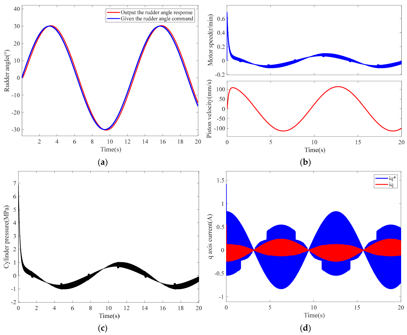
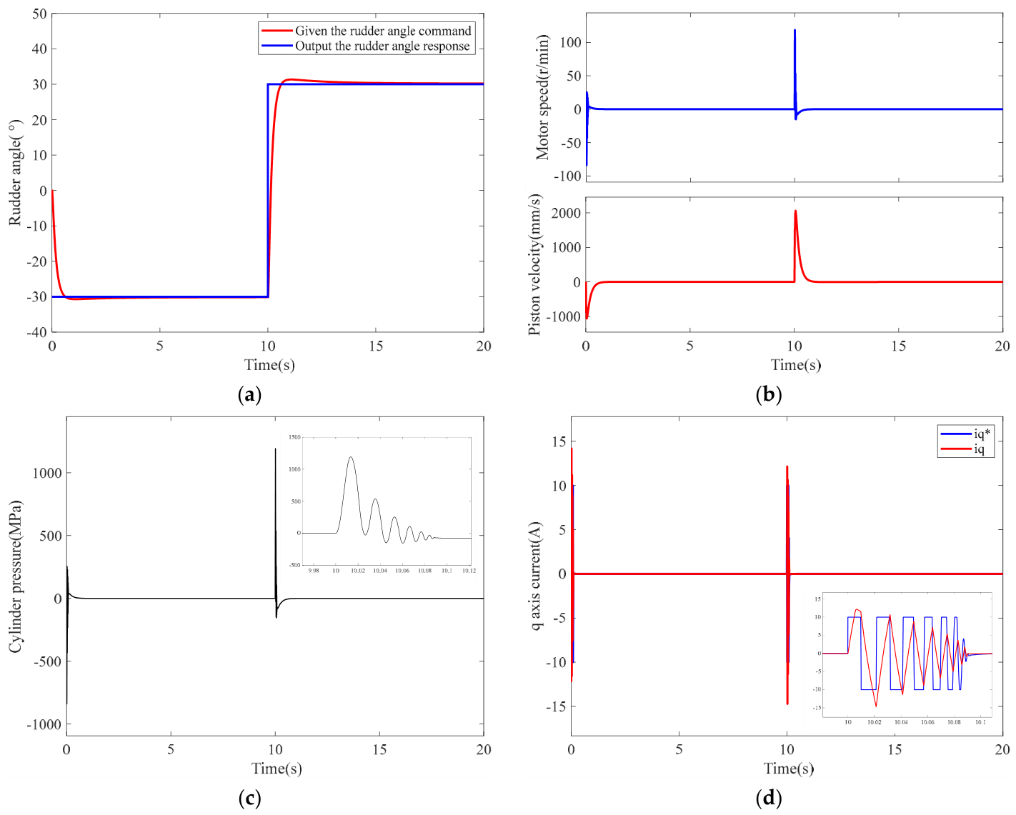
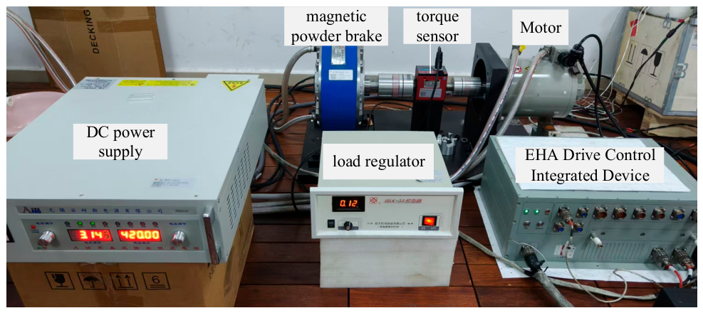
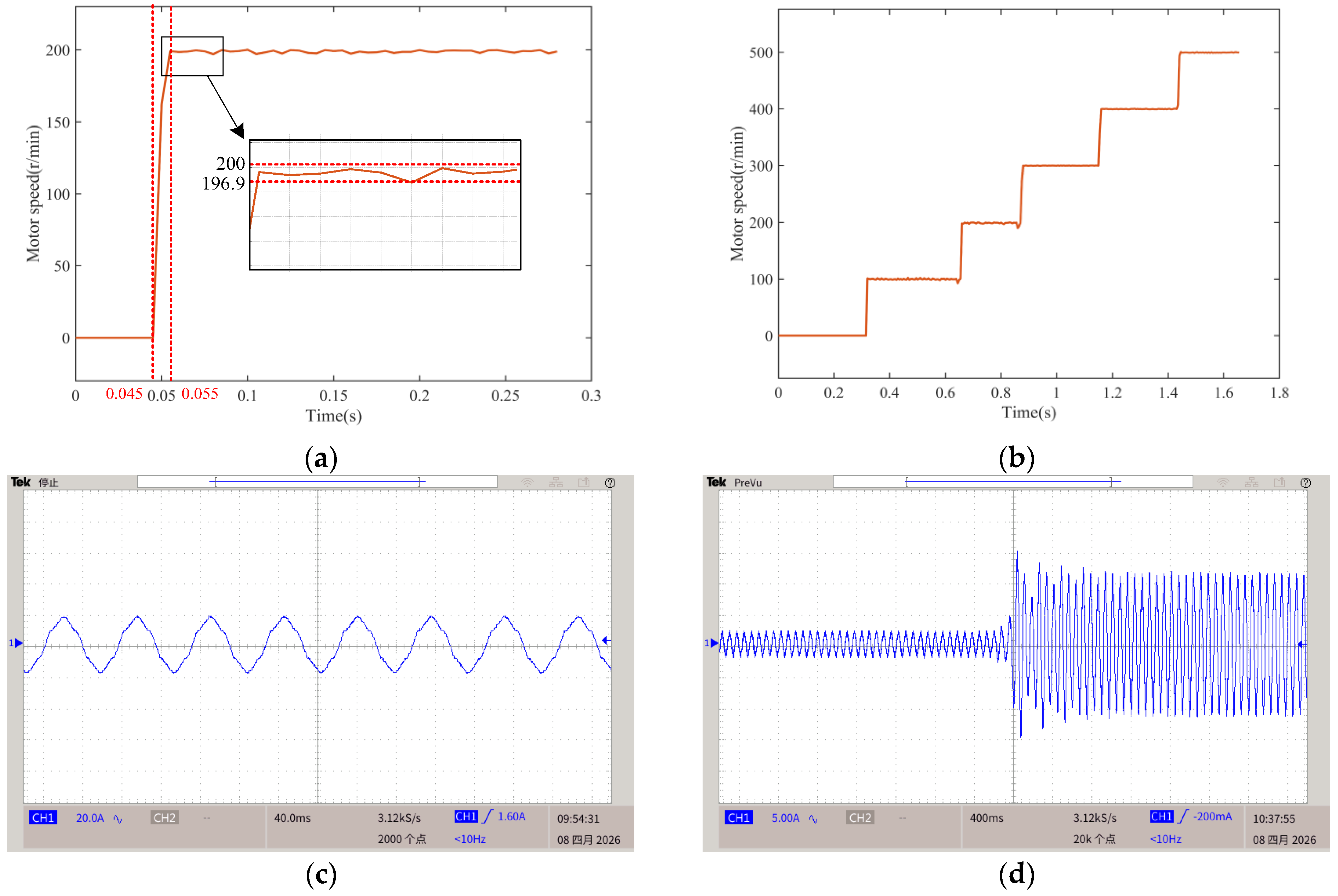
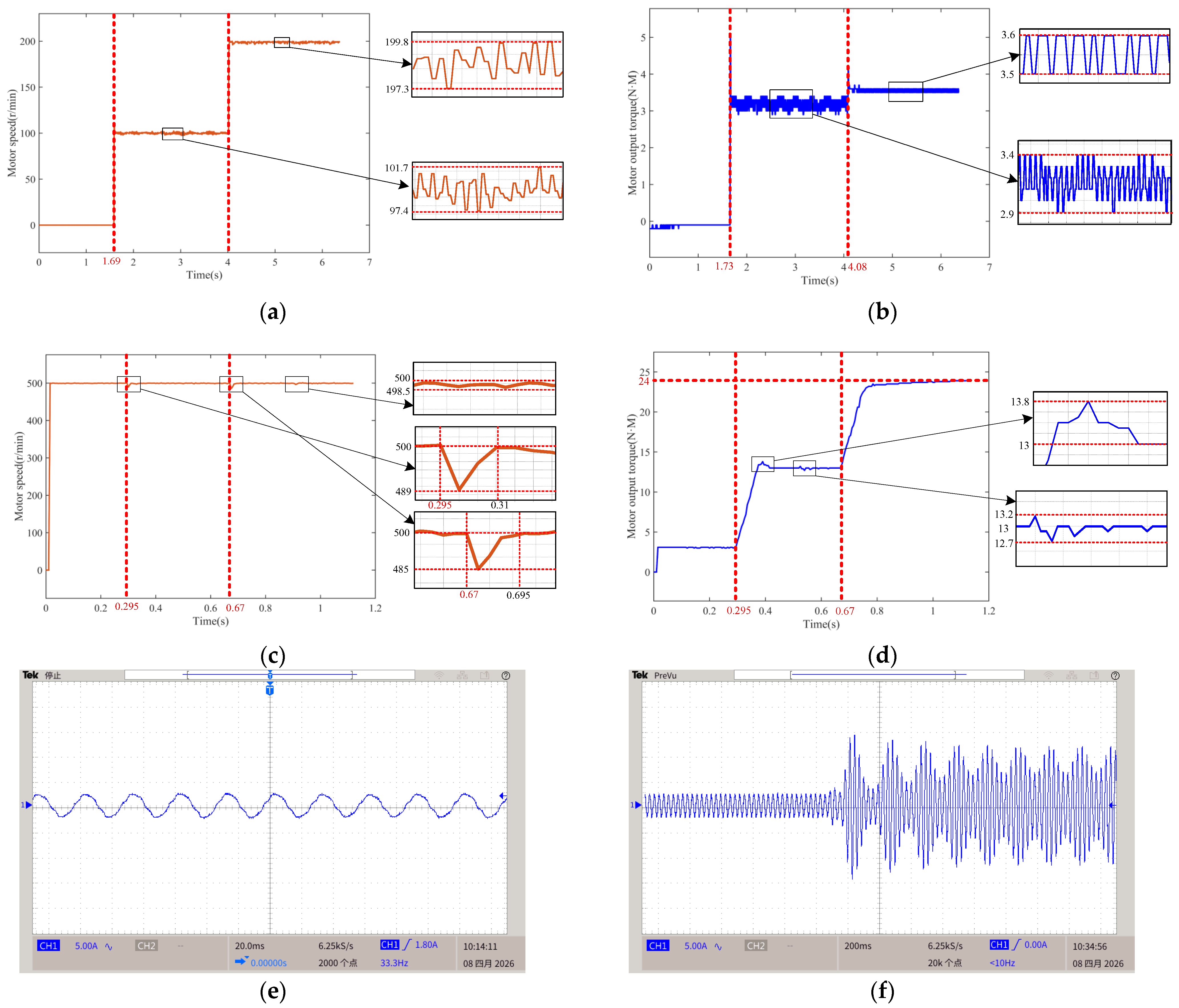
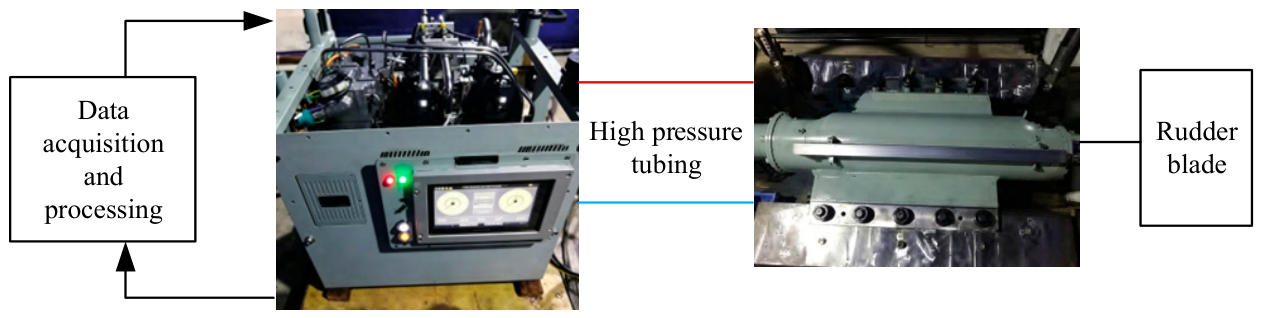
Regarding experimental validation, a comprehensive system simulation model and a phased bench-test platform are established. Simulation results confirm the excellent performance of the proposed composite control strategy under step and sinusoidal commands. The experimental campaign comprises two parts: drive motor performance tests and overall system joint debugging. Key performance indicators—including speed regulation characteristics, load disturbance rejection, rudder angle tracking accuracy, rudder speed response, and hydraulic stability—are systematically evaluated. Experimental results show that all core performance indicators meet and exceed the general technical standards for marine steering systems. The deviation between experimental data and simulation results is within 5%, confirming the accuracy of the developed model and the effectiveness of the control strategy. Furthermore, experimental repeatability and measurement uncertainty are analysed. All operating conditions are tested three times, with coefficients of variation for key indicators below 2%, and the overall measurement uncertainty satisfies engineering test requirements, thereby enhancing the reliability of the experimental results.
The findings of this paper provide a comprehensive theoretical methodology and a reliable experimental basis for the performance optimisation of EHA systems for ship steering, and lay the technical foundation for their application in demanding scenarios such as large ocean-going vessels. Nevertheless, it should be noted that the bench tests presented here constitute a small-scale proof-of-concept study; the applied loads of 10 N·m and 20 N·m are used solely to verify core system performance and control effectiveness, and do not yet replicate the actual high-load (tens to hundreds of kilowatts) operating conditions of large-vessel steering systems. Extending the proposed EHA system to real maritime load conditions still faces key technical challenges, including thermal management, high-inertia load matching, high-power dynamic response constraints, and long-term reliability under harsh environments. In future work, methodologies such as adaptive sliding mode control and multi-model switching control will be employed to increase the power rating and enhance the heat dissipation scheme, thereby improving system robustness and adaptability. Long-term real-vessel trials will also be conducted to gradually advance the engineering adaptation of the system to high-load steering conditions of large ocean-going vessels.