1. Introduction
Recent successful demonstrations of fusion ignition at the National Ignition Facility [
1,
2] have marked a major milestone and opened the path toward alternative fusion schemes that might produce higher energy gains. One of the promising routes toward achieving higher gain is fast ignition (FI) [
3], which separates compression and ignition stages. By using a short, high-intensity pulse to locally heat the compressed fuel, FI relaxes the energy requirements on compression and ignition conditions and thereby enables higher overall gain [
4]. (Unless specified, gain refers to the ratio between fusion energy and total laser energy
.) In the initially proposed electron-driven FI scheme [
3], the heating laser is used to generate relativistic electrons, which transfer energy to the compressed fuel. The laser focal spot size directly affects the properties of the relativistic electron beam. It sets the transverse size of the electron source and, for a fixed laser energy and pulse duration, determines the laser intensity on the target. The intensity influences the electron energy spectrum and may also affect the electron divergence. Together, these properties determine how efficiently fast electron energy is transported to and deposited in the compressed fuel, thereby affecting the achievable target gain
. For a fixed pulse energy and duration, increasing the focal spot reduces the peak intensity and increases the effective source size, both of which can degrade coupling to the FI target. As was shown, in the case of poor laser contrast, maximal energy efficiency is achieved for laser spot sizes of approximately
[
5]. This is consistent with the scaling analysis [
6], which showed that a
laser requires a spot size below approximately
to achieve high gain. Although larger spot sizes can provide improved efficiency in the case of ultra-high contrast pulses [
5], there is strong evidence that the cone tip is filled with pre-plasma during the compression stage due to shock wave propagation through the cone [
7,
8,
9]. Therefore, pre-plasma effects remain non-negligible even for an ultra-high contrast ignitor pulse. Under these conditions, enhancing the laser intensity on the target by achieving smaller focal spots within the geometric constraints typical for the FI facilities may provide a viable path toward improved coupling efficiency [
5].
In the more recently developed ion-driven FI scheme [
10,
11], the short pulse laser transfers energy to the ions through laser-driven ion acceleration mechanisms like target normal sheath acceleration [
12]. The ions then deposit their energy in the compressed target, heating it. Therefore, significant effort has been dedicated to improving ion beam generation and transport, including enhanced focusing and tailoring of the ion energy spectrum [
13,
14,
15,
16,
17,
18]. These works have aimed at satisfying the requirements of the particle beam deposited in the target, which can be expressed in terms of the power density, typically ∼
[
19]. Numerical analyses show that the ion beam diameter should be in the range of 15–35
[
20] to minimize the required ignition energy. This requirement is challenging for the kJ-class laser systems with focal spots, which are typically considerably larger, even without taking into account ion beam transport. In addition to that, the intensity-on-target requirement becomes even stronger for advanced acceleration regimes such as radiation pressure acceleration [
21] or break-out after burner [
22], which potentially offer significantly higher energetic ion yield in the required energy range. Therefore, a compact optical element capable of increasing ignitor intensity inside the cone could relax the driver energy requirements and improve coupling in ion-driven FI schemes.
Typical cone-guided FI targets employ reentrant cones with full opening angles of approximately 30°–70°, while the tip diameter is typically chosen to be comparable to the compressed core size, on the order of 10–40
[
23]. Such geometries impose significant constraints on the focusing optics used for the ignition beam. As a consequence, the available focusing geometry typically results in relatively large focal spot sizes compared with those achievable using short
optics such as off-axis parabolas. In existing FI facilities, the ignition laser focal spots are typically on the order of 40–50
, as shown in
Table 1, in which relevant laser parameters are summarized. This limits the intensity on target and directly affects the conversion efficiency of laser energy to energetic ions or hot electrons. For example, the work of Kitagawa et al. [
24] experimentally demonstrated direct fuel heating by energetic ions using the LFEX laser with an
lens focused on a 60-micron-diameter spot. A similar spot size has been reported in initial experiments with OMEGA EP [
8] and LMJ PETAL [
25]. These limitations show the need for novel focusing approaches capable of improving coupling efficiency under the constraints imposed by FI scheme geometry.
In this work, we propose a compact approach that enables focal spot sizes comparable to those produced by short
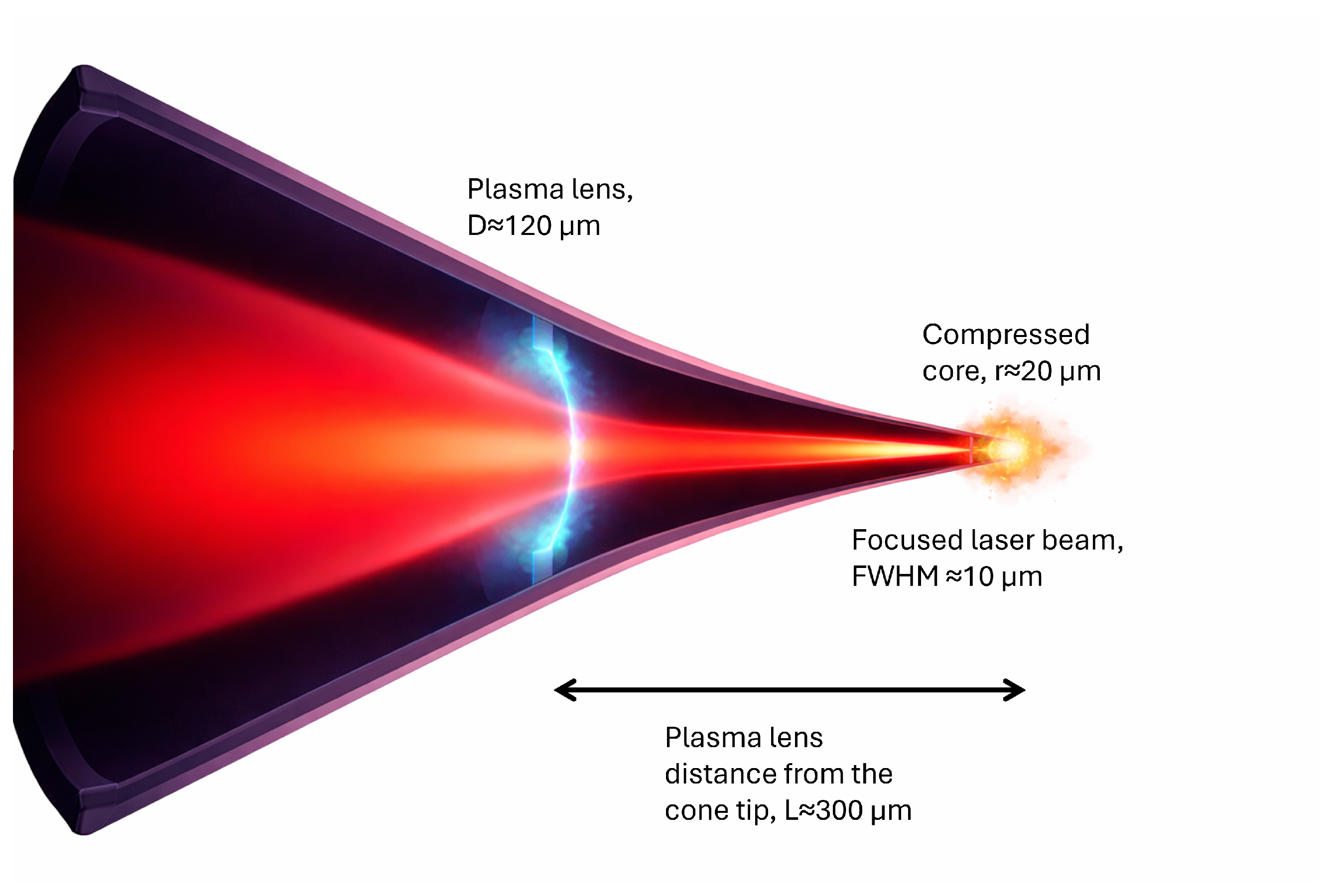
off-axis parabolas while remaining compatible with the geometric constraints of cone-in-shell targets, thereby allowing the formation of micron-scale focal spots located inside the cone. In the proposed approach, shown in
Figure 1, a foil with a central aperture is placed inside the cone of a FI target, located at a sub-millimeter distance from the cone tip. A nanosecond pulse irradiates the foil, leading to ionization and plasma expansion from the aperture edges. This expansion produces a radially decreasing plasma electron density profile, which results in a corresponding refractive index gradient that acts as a transient focusing element for the second pulse. Due to the nearly uniform illumination around the aperture, we assumed the azimuthal symmetry of the expanding plasma. Then, the plasma refractive index can be written as
where
is the local plasma frequency,
is the laser frequency,
is the electron density, and
is the critical plasma density. As a result, the subsequent pulse is tightly focused to a significantly smaller spot size near the compressed target, enhancing the on-target intensity within the geometric constraints of the cone.
Previous demonstrations of plasma-based laser focusing included capillary discharges [
28,
29], laser ablation of the capillary entrance [
30], ellipsoidal plasma mirrors [
31], hollow plasma fibers [
32], and holographic plasma lenses [
33]. While these approaches have shown impressive focusing capabilities, their direct application to FI is limited by geometric and temporal constraints. Capillary- and discharge-based schemes require structures that are much larger than the space available in the vicinity of a cone, and their plasma formation times are often longer than the nanosecond compression dynamics relevant to FI. Similarly, holographic plasma lenses rely on gas jets to prepare the plasma structure, introducing expansion times that are usually longer than the characteristic compression timescale. Ellipsoidal plasma mirrors, although formed on much shorter timescales, typically have dimensions comparable to those of conventional optical elements and are therefore hard to integrate into the constrained cone geometry. Therefore, despite strong numerical and experimental demonstration, these approaches are not directly compatible with the FI target requirements. In our proposed design, the dimensions of the plasma lens have been reduced to approximately 100
m, which means it can be installed directly inside the cone target near the interaction region. In addition to that, the lens formation time is below 10 ns, which is well compatible with typical fuel compression timescales. Beyond FI applications, compact plasma lenses of this type may also provide miniature transient optical elements for a broad range of laser–plasma experiments, particularly in configurations where conventional optics are limited by space constraints, laser-induced damage thresholds, or proximity to the interaction region.
The following section describes the experimental setup and diagnostics used to generate and characterize the plasma lens. The main experimental results are presented in
Section 3, followed by their analysis and discussion in
Section 4. Finally,
Section 5 summarizes the main findings.
2. Methodology
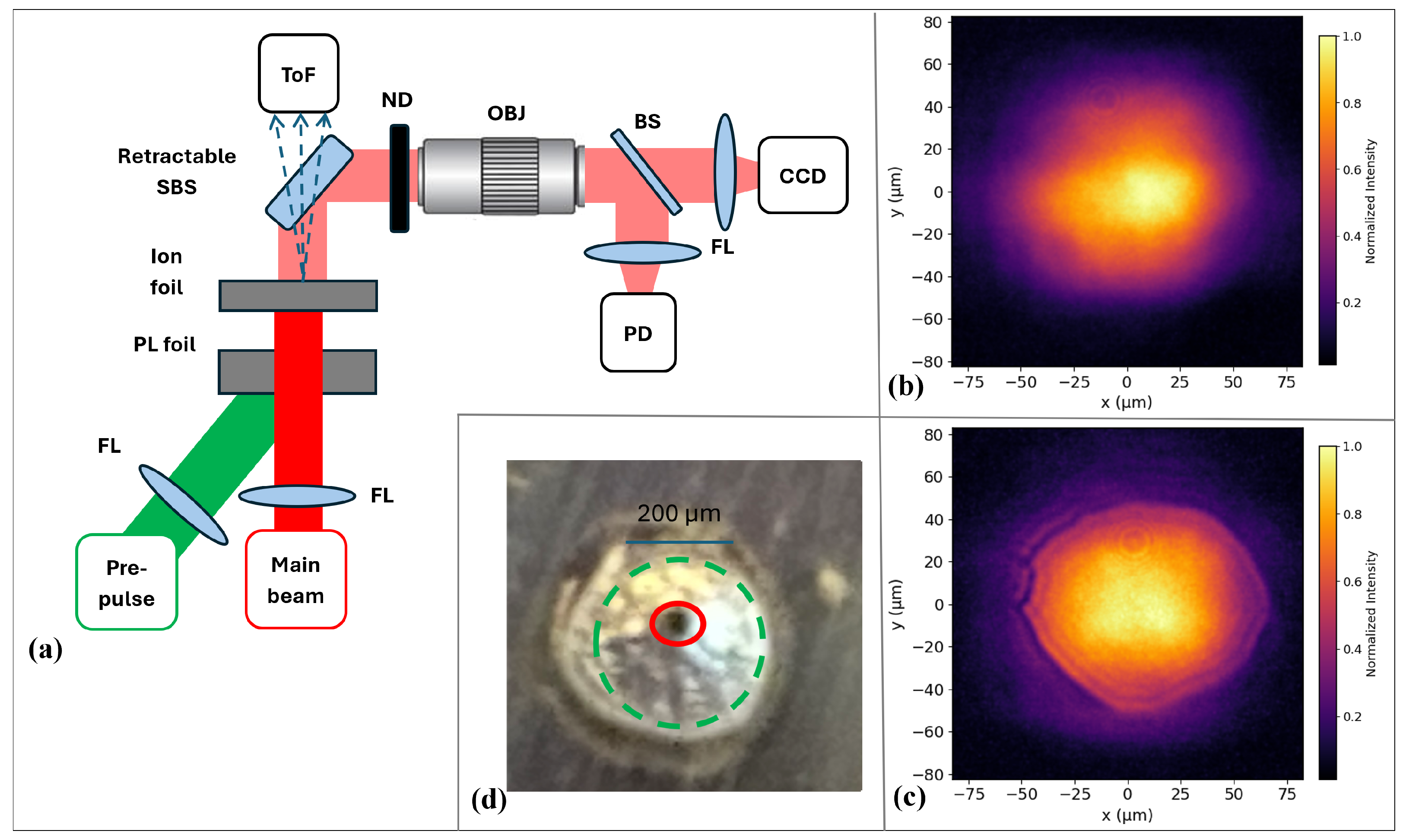
The experiments were performed at the High Intensity Laser Laboratory at the Hebrew University of Jerusalem. In the present proof-of-concept configuration, a flat foil with a laser-drilled aperture is used to emulate the aperture that would be placed inside a FI cone while allowing repeatable multi-shot optimization of the experiment parameters (a schematic of the setup is shown in
Figure 2a). The foil is positioned inside the main interaction chamber under a vacuum, with a typical pressure of ∼
. The experiment is based on a two-pulse configuration consisting of a nanosecond preceding pulse, which is used to generate a transient plasma lens and a delayed femtosecond main pulse that propagates through the plasma-filled aperture.
The plasma lens was generated using a frequency-doubled Nd:YAG laser at a 532 nm wavelength, delivering 8 ns pulses with tunable energy in the range of 80–200 mJ. The laser beam, with a diameter of 15 mm, was focused onto the foil around the aperture using a lens of focal length cm. The foil was intentionally placed beyond the focus of the nanosecond pulse to obtain a spot times larger than that of the main pulse to ensure uniform plasma formation around the aperture and simplify alignment constraints between the plasma lens target and the two beams. The first pulse is incident at an angle of approximately with respect to the target normal in order to minimize direct irradiation of the downstream ion-generating foil by the portion of the nanosecond beam transmitted through the aperture, which may inhibit ion acceleration. Irradiation of the aperture edges by the nanosecond pulse led to ionization and plasma expansion, producing the transient radial density profile that leads to plasma lens formation on the timescale of the first pulse duration.
The main pulse was provided by a Ti:Sapphire Spectra-Physics ACE laser system operating at a central wavelength of nm, with a pulse duration of fs and energy on target of mJ. The beam, with a diameter of 10 mm, was focused by a plano-convex lens of focal length cm and was normally incident on the foil . At the plasma lens foil position, the main beam had an elliptical full width at half maximum (FWHM) of and , comparable to the aperture size, to ensure efficient transmission. Temporal synchronization and delay control between the first laser and the main pulse is done with an ISEO Masterclock delay controller with 1 ns tuning resolution and typical jitter below 50 ps.
The plasma lens target is made of an 83 m thick aluminum foil mounted on a motorized three-axis translation stage with micrometer precision. A circular aperture was formed in the foil by repeated irradiation with the main pulse at 10 Hz. The resulting aperture diameter was typically in the range of ∼60–120 m and could be adjusted by translating the foil along the optical axis of the main beam. This aperture generation procedure ensured precise alignment of the main pulse through the center of the plasma-filled opening. The effective focal position and focal spot obtained with the plasma lens depended sensitively on the plasma density profile, which was controlled by the ns pulse fluence and by the delay between the two pulses.
For optical characterization, the sampling beam splitter (SBS) extracted a fraction of the transmitted main beam for diagnostics. The beam profile was imaged onto a CCD camera using an infinity-corrected objective mounted on a linear translation stage, protected by neutral density filters to prevent laser-induced damage to the objective. A second beam splitter directed part of the sampled light onto a calibrated PD connected to a high-bandwidth oscilloscope, enabling shot-to-shot monitoring of the transmitted pulse energy. Beam profiles were analyzed using custom Python scripts (version 3.12.8).
To characterize the impact of the plasma lens on secondary particle generation, a second foil target was placed behind the plasma lens in its focal plane. This target consisted of a 10
m thick aluminum foil mounted on a motorized three-axis translation stage and positioned parallel to the plasma lens foil. Interaction of the focused main pulse with this secondary foil generated energetic ions through the target normal sheath acceleration (TNSA) mechanism [
12]. Ion emission was measured using a Time-of-Flight (ToF) diagnostic consisting of a 1.4 m flight tube connected to the main vacuum chamber. At the end of the tube, the particles were detected using a scintillator coupled through a light pipe to a photomultiplier tube and recorded on a fast oscilloscope. An EJ-590/B10 aluminized mylar film (Eljen Technology, Sweetwater, TX 79556 USA) placed in front of the scintillator acted as an energy filter, suppressing slow electrons and rejecting the low-energy ions.
3. Results
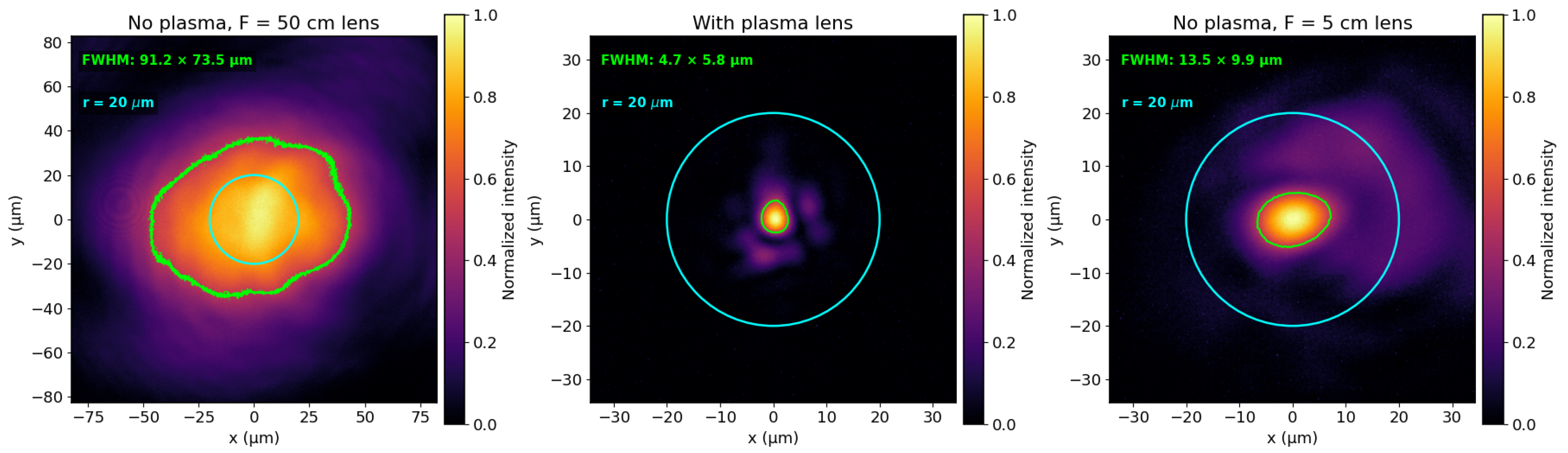
The main pulse was first characterized in the absence of the plasma lens target in order to establish the reference focusing with the long focal lens only. The measured beam quality factors were and , indicating a slightly elliptical beam. Without any target in the beam path, the full pulse energy corresponded to a PD signal of = 38.5 ± 3.7 mV, which was used as the reference signal . The focal spot produced without the plasma lens, only by the long focal lens, had an FWHM size of with a contour area .
For the plasma lens shown in
Figure 3, a laser-drilled aperture had the size
, consistent with the typical dimensions used in the experiments. In the absence of the ns pulse, the aperture clipped the incident main beam. This reduced the transmitted energy to
, with a typical example shown in
Figure 2c. This aperture-only case provides the reference for separating losses caused by geometric clipping on the edges of the aperture from the losses due to transmission through the plasma.
When the nanosecond pulse was applied, a clear focusing effect was observed. The plasma lens produced a focal spot substantially smaller than that obtained in the long-focus case and comparable in scale and CCD pixel intensity to that obtained using the short focal length lens. The smallest laser focal spots were observed for a delay of
between the first and the second pulse peaks. Under these conditions, the transmitted main beam was focused to an FWHM spot size of
with FWHM pixel contour area
, with a typical shot shown in
Figure 3. Compared with the focal spot without the plasma lens, this corresponds to an FWHM area reduction factor
The plasma lens focus was observed at a distance of ∼100–300
from the back surface of the plasma lens target, consistent with the requirement for a compact focusing element that can work close to the interaction region. To quantify the real intensity enhancement, the analysis must include both the reduction in the focal area and the energy transmitted through the aperture and plasma. Averaged over the analyzed plasma lens shots, the transmitted energy measured by the PD was
(this represents total transmission through the plasma lens including both aperture clipping and laser–plasma interaction losses). The PD measurement gives the total transmitted pulse energy, but it does not determine how much of this energy is concentrated in the FWHM contour. Therefore, the spatial energy concentration was evaluated directly from the CCD intensity. After background subtraction, the energy fraction inside the FWHM contour was calculated as
For the long-focus reference case, this fraction was whereas for the optimized plasma lens case, it was Using the measured energy fraction avoids assuming an ideal Gaussian profile and accounts for the experimentally observed halo and low-intensity background around the focused spot in the case of the plasma lens.
The effective intensity enhancement averaged over the FWHM region can then be written as
Here, accounts for the total transmission of the laser pulse through the plasma lens, including losses at the aperture and absorption in the plasma. The ratio represents the fraction of the transmitted energy contained within the FWHM region for the plasma lens and vacuum cases, respectively, thereby capturing changes in the spatial energy distribution at the focus. Finally, the area ratio accounts for the change in FWHM spot size. Thus, although the aperture introduces a non-negligible loss, the reduction in focal area more than compensates for it, resulting in a net increase of the laser intensity on target. For comparison with FI-relevant focusing conditions, the measured plasma lens spot was also compared with a typical ignitor beam radius of . Assuming the same energy transmission, the effective intensity enhancement is This demonstrates that a compact plasma lens can generate focal intensities comparable to those usually associated with much shorter focal length optics while preserving a geometry compatible with restricted cone access configurations.
The dependence of the focusing effect on the delay between the nanosecond pulse and the femtosecond main pulse was investigated over the range At shorter delays, the plasma expansion was insufficient to generate the radial density gradient required for strong focusing, and the transmitted beam remained close to the aperture-only reference case. At longer delays, the focal spot broadened and the transverse profile became less compact, indicating that the plasma density profile had evolved beyond the optimum condition. The best focusing was obtained at , where the FWHM spot size reached its minimum value and the measured intensity enhancement was maximal.
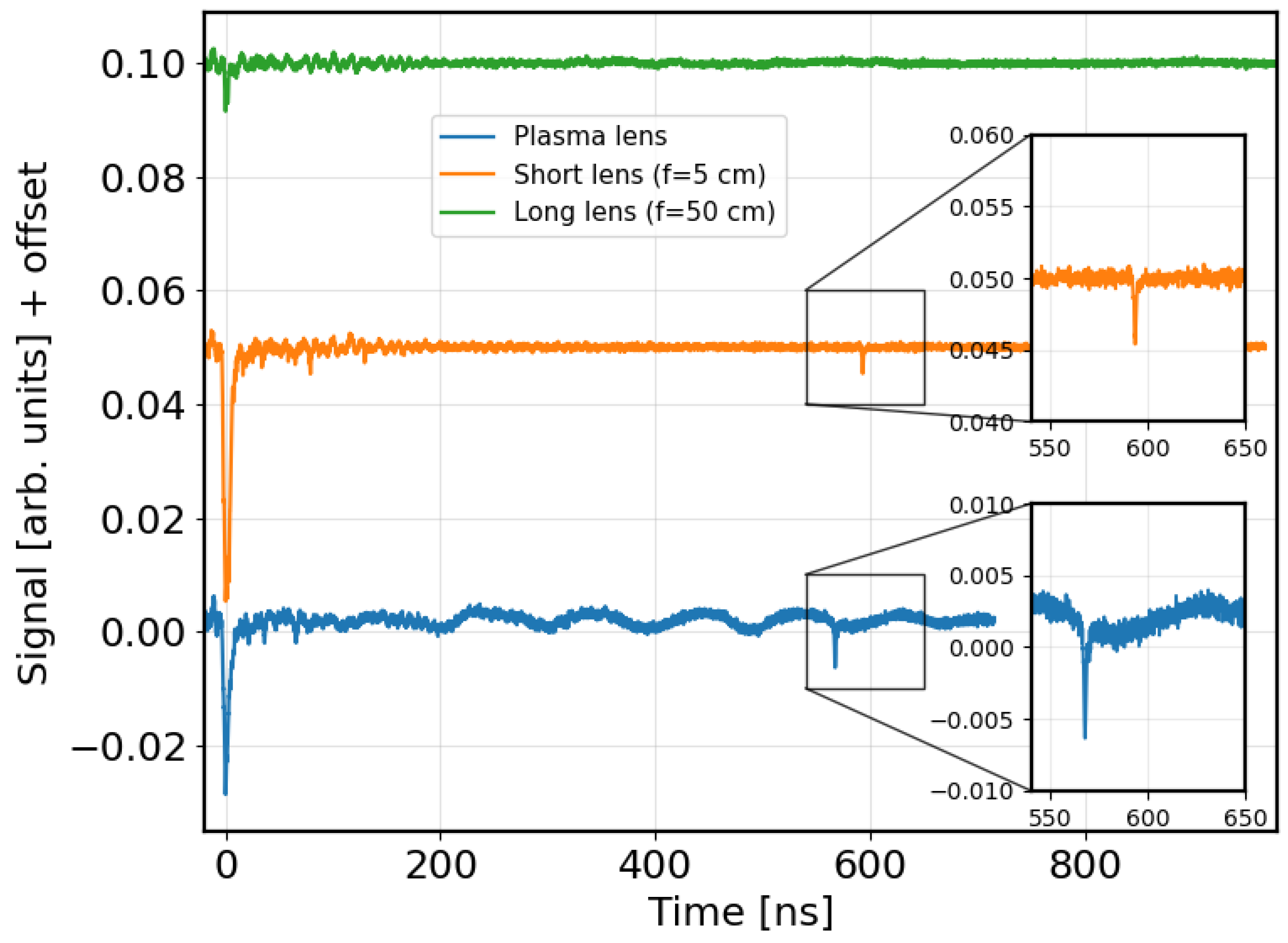
To assess whether the optical intensity enhancement produced by the plasma lens leads to the generation of more energetic ions, a 10 m thick Al foil was placed in the plasma lens focal plane. The sampling beam splitter was removed to allow full propagation of the transmitted particle beam into the ToF diagnostic. Three configurations were compared: (i) the long-focus reference case without the plasma lens target, (ii) a conventional short focal length reference case ( cm), and (iii) the long-focus geometry with the plasma lens activated.
Typical ToF peaks are shown in
Figure 4. In all cases, the initial peak is used as the time reference and is attributed to energetic photons and fast electrons. Delayed peaks, if present, were interpreted as ion signals. The ion kinetic energy was estimated from the arrival time relative to the initial peak. In the long-focus reference case without the plasma lens, no delayed ion peaks were detected in any of the shots, and the photopeak amplitude was lowest. In contrast, when the plasma lens was activated, the amplitude of the photopeak increased by approximately a factor of five, and clear delayed ion peaks were observed. Assuming Al ions, the earliest detected peak corresponds to a maximum ion energy of
. A similar response was observed for the short focal length reference case, with a maximum ion energy of
under the same assumption and a comparable photopeak amplitude.
4. Discussion
The experimental results shown in
Figure 3 demonstrate that the plasma produced at the aperture edges acts as a transient focusing element for the femtosecond pulse. The resulting reduction in focal spot size compensates for the energy losses introduced by the aperture and plasma transmission, leading to a net increase in the on-target intensity. The aperture-only case transmitted
of the incident main pulse, while the active plasma lens case transmitted
. Since
includes both aperture clipping and plasma-related losses, the comparison shows that the dominant energy loss is due to the finite aperture, whereas the plasma adds only a modest additional loss of approximately
However, the spatial energy distribution at the focus shows a low-intensity halo around the focused beam. Analysis of the CCD images shows that only ≈ of the energy is contained within the FWHM contour in the plasma lens case, compared to ≈ for the vacuum reference. There are several effects that might have caused the observed halo. The nanosecond beam profile showed hot spots that can lead to an inhomogeneous plasma density distribution and distort azimuthal symmetry, which will distort the refractive index profile of the lens. The oblique incidence of the nanosecond pulse introduces azimuthal asymmetry in the plasma formation, further perturbing the focusing conditions. The laser drilling of the aperture can also lead to asymmetry by nonuniform aperture edges and wall profiles. These effects can perturb the plasma density distribution and reduce the fraction of energy concentrated in the central focal spot. Normal incidence illumination and more reproducible aperture fabrication are therefore expected to improve the azimuthal symmetry of the plasma lens and increase the energy concentration within the focal spot. In addition, shot-to-shot fluctuations in the plasma formation result in variations in the focal plane position. The shot-to-shot stability of the focus was assessed by moving the imaging system around the best focus position. A shift produced a clear change in the imaged focal spot, indicating that the plasma lens focus is localized and reproducible on this scale.
The optimal delay
ns between the pulses is consistent with hydrodynamic expansion of the plasma from the aperture edges toward the axis. For an initial aperture diameter of ≈100
m, a radial closure distance of ≈
m is required to form a sufficiently strong density gradient near the center. For the present nanosecond Al ablation conditions, reported temperatures of the laser-produced Al plasma under comparable conditions are on the order of several eV [
34]. Taking a representative range of
–
and
–2, the ion acoustic speed is
–
for Al. This gives a filling time of ∼6–
, consistent with the observed optimum delay at
. At shorter delays, the plasma expansion is insufficient to establish the required refractive index gradient, resulting in weak or absent focusing. At longer delays, the expanding plasma will collide near the aperture center, producing a density ramp in the center of the aperture. As a result, the plasma can partially defocus or scatter the beam, increasing the halo and reducing the energy contained in the FWHM core.
The ToF measurements provide an independent indication that the observed intensity enhancement produced by the plasma lens is sufficient to achieve ion-accelerating conditions at the secondary foil. In the long-focus reference case, where the main pulse reaches the secondary foil at the focal plane, no delayed ion signal was detected in any of the shots. In contrast, when the plasma lens was activated, a delayed ion signal appeared after the initial photopeak. A similar signal was observed in the conventional short-lens reference case. The comparison between the three configurations shows that the plasma lens geometry produces interaction conditions qualitatively similar to those obtained with a much shorter focal length optics.
The observed single ion peak can be attributed to the diagnostic limitations. Laser-driven ion acceleration from a thin foil is expected to produce a broad ion energy distribution. However, in the present diagnostic configuration, the measured ion signal is cut by the energy filtering introduced by the aluminized mylar film. As a result, only the highest-energy part of the accelerated ions is capable of reaching the scintillator. According to SRIM calculations [
35], the present filter configuration allows transmission of H, O, and Al ions only above
MeV,
MeV, and
MeV, respectively.
The approximately fivefold increase in the photopeak amplitude in both the short-focus and plasma lens cases further supports the conclusion that the laser–solid interaction at the secondary foil is stronger than in the long-focus reference case. Since the photopeak is produced by fast electrons and energetic photons reaching the scintillator, its increased amplitude is consistent with enhanced laser intensity on the ion-generating target.
Overall, the ToF results support the optical diagnostics by showing that the plasma lens configuration produces secondary foil interaction conditions comparable to those obtained with a conventional short-focus lens, while the long-focus reference case does not produce a detectable delayed ion signal.
The conducted experiments were performed with a low-energy femtosecond laser and therefore demonstrate relative intensity enhancement at energies and intensities below those of FI-scale laser systems. Under typical FI conditions due to relativistic laser intensity, such nonlinear effects as relativistic self-focusing, ponderomotive modification of the electron density, relativistically induced transparency, and plasma heating may modify the refractive index profile during the pulse and therefore change the focusing performance. Therefore, additional optimization will be required to tailor the plasma profile while considering nonlinear effects.
The plasma lens was characterized in a simplified flat foil geometry, rather than inside an actual cone target. For sufficiently open cones and lens positions far enough from the cone tip, the cone boundary should not prevent plasma lens formation. The available cone diameter at a distance L from the tip can be estimated as , where is the cone tip radius and is the full cone opening angle. For typical FI cone parameters, and to , which gives to at and to at . These values are comparable to, or larger than, the aperture diameter used in the present experiment, . However, in narrow cones, when the aperture is placed close to the cone tip, the cone edges may limit the available aperture size and modify the plasma expansion. In this case, interaction of the expanding plasma with the cone walls may increase the plasma density near the boundary and distort the radial density profile required for optimal focusing. Therefore, flat foil provides initial experimental guidance for optimal aperture distance from the tip, diameter and thickness, which must be optimized for particular FI cone geometry. In addition, the ToF diagnostics cannot provide ion species separation, so the inferred ion energies assume the same ion species. This assumption is supported by the comparable intensities observed in the focus imaging diagnostics for the short lens and plasma lens configurations. It is important to note that due to the aluminized mylar filter, the absence of a delayed ion signal in the long-lens reference case indicates that ions with sufficient energy to penetrate the filter were not detected. Therefore, future experiments using a Thomson parabola spectrometer or other ion-specific diagnostics and higher-energy laser pulses will be required to quantify the ion spectrum, conversion efficiency, and scalability of the miniature plasma lens for FI applications.
The experimental results demonstrate several features relevant for FI applications. First, the transient plasma lens is not constrained by the laser-induced damage thresholds that limit conventional optics. Second, its characteristic dimensions are sufficiently small to be compatible with the restricted space near the FI target and within the cone geometry. Finally, the measured focal spot is approximately an order of magnitude smaller than the typical spot sizes reported for large-scale FI facilities. Together, these results support the use of compact plasma optics as a viable route for increasing the ignitor beam intensity in geometrically constrained FI experiments.
5. Conclusions
We have demonstrated an experimental proof-of-concept of a compact transient plasma lens that enhances the intensity of a long-focus femtosecond laser beam in a flat foil geometry. A nanosecond laser ionized the surface around the aperture in Al foil. Expansion of the plasma generated a density gradient that focused a delayed femtosecond pulse into a micron-scale spot located a few hundred microns behind the plasma lens. In the optimized configuration, the effective intensity enhancement of ≈47 ± 15 after accounting for energy transmission and spatial energy distribution was observed. The ToF measurements from a secondary foil target showed that the plasma lens configuration recovered ion generation conditions comparable to those obtained with a conventional short-focal-length lens, while no ion signal was detected in the long-focus reference case. These results demonstrate that compact plasma lensing is a promising route for overcoming geometric focusing constraints in cone FI configurations while also highlighting the potential of miniature plasma optics for a broad range of high-intensity laser–plasma applications. The proposed approach offers a potential route to increasing the intensity of fast-ignition laser beams under the geometric constraints of typical FI configurations. However, the achievable focusing performance and energy transmission at relativistic laser intensities remain to be demonstrated and will require further investigation under realistic FI conditions. The present results demonstrate the feasibility of the plasma lens concept and motivate further work to optimize the lens geometry, characterize the accelerated ions, and quantify the achievable focusing performance under laser and target conditions approaching those required for fast ignition.




 ,
,