Article

Effects and Flow Control Mechanism of Synthetic Jets in a Transonic Axial Compressor

1
Yanzhao Electric Power Laboratory, North China Electric Power University, Baoding 071003, China
2
Hebei Key Laboratory of Low Carbon and High Efficiency Power Generation Technology, North China Electric Power University, Baoding 071003, China
*
Author to whom correspondence should be addressed.
Appl. Sci. 2026, 16(11), 5447; https://doi.org/10.3390/app16115447 (registering DOI)
Submission received: 5 May 2026 / Revised: 20 May 2026 / Accepted: 22 May 2026 / Published: 30 May 2026
(This article belongs to the Special Issue Aerodynamic Design and Analysis of Turbomachinery)

Abstract

To address flow instability induced by tip leakage vortex breakdown in high thrust-to-weight ratio aero-engine compressors, this study conducts numerical investigations into the DTR transonic compressor rotor. The unsteady evolution of the tip leakage vortex and the corresponding stall inception mechanism under near-stall conditions are revealed. Active flow control using single-slot and dual-slot endwall synthetic jets is further explored. Results show that an optimized single synthetic jet slot improves the compressor stability margin by 11.24% and design-point efficiency by 0.57%. To address the flow instability on this, synergistic excitation using two slots positioned at 25% and 50% axial chord length further suppresses leakage vortex breakdown and passage blockage, raising the stability margin by an additional 13.68% and efficiency by 0.72% compared to the optimal single-slot configuration. For the baseline compressor under near-stall conditions, tip leakage vortex breakdown occurs near 25% axial chord, causing severe flow deterioration. With synthetic jet actuation, low-energy fluid at the tip is blown away or sucked out, delaying vortex breakdown and reducing flow losses, thereby enhancing stability without compromising aerodynamic efficiency. The underlying mechanism is that, during the blowing phase, the jet splits the large-scale leakage vortex and removes the low-energy blockage region; during the suction phase, it extracts the fluid trapped in the tip clearance, preventing re-accumulation of low-energy fluid. These findings provide theoretical guidance for stall suppression and high-performance design of transonic compressors.

1. Introduction

The rapid development of the modern aviation industry demands ever-higher aero-engine performance. High thrust-to-weight ratio, low fuel consumption, and a wide stable operating range are core objectives for next-generation engine development. As a key component of the compression system, the transonic axial compressor directly influences the overall engine performance [1]. To meet the design requirements of high pressure ratios, the stage loading and single-stage pressure ratio of transonic compressors continue to increase [2], making the flow environment inside the blade passage increasingly complex [3]. Flow structures including tip leakage flow, shock waves, and boundary layer separation interactions, induce unsteady flow instability issues [4,5]. Under near-stall conditions, vortex-wave interference will directly lead to the breakup of the leakage vortex [6]. It is verified by Mach number distribution and vortex identification based on the Lambda-2 criterion, as well as helicity and vorticity analysis, that the tip leakage vortex breaks down near 25% axial chord, with two breakdown events occurring within one periodic cycle. After breakdown, the vortex structure disintegrates into numerous small-scale vortex clusters, which mix with low-momentum fluid and accumulate in the tip passage, resulting in a sharp reduction of the effective flow area [7] and flow overflow at the blade leading edge [8]. This series of flow evolution processes will eventually induce rotating stall or surge, which will lead to a significant decrease in compressor efficiency, and even cause damage to the engine structure and threaten flight safety.
Flow control technology is an effective means to improve the internal flow of the compressor and improve the aerodynamic stability. According to whether external energy input is needed, it can be divided into two categories: passive control and active control [9]. Passive control technology mainly improves the flow by optimizing the blade geometry and casing modeling, such as blade tip winglet [10], casing treatment [11], vortex generator [12], and surface roughness [13]. This technology requires no external energy input and features a simple structure, but its control performance is highly sensitive to operating conditions and difficult to sustain under off-design conditions. Active control technology applies targeted disturbances to the flow field through external input energy, and can adjust the control strategy in real time according to the change of working conditions. The flexibility and effectiveness of control are far better than passive control [9]. Among them, synthetic jet technology has become a research hotspot in the field of active flow control of turbomachinery due to its advantages of no external gas source, compact structure, fast response speed and wide frequency band. The synthetic jet [14,15] is also known as a zero-net-mass-flux jet. Through the reciprocating motion of the vibrating film inside the actuator [16], the periodic blowing and suction of the jet outlet are realized, and an orderly jet structure is formed in the flow field. No additional gas supply system is required, which greatly reduces the difficulty of engineering application and is very suitable for arrangement in a narrow space inside the compressor.
Synthetic jet technology [17] is used to apply micro-disturbance to the fluid near the endwall through the reciprocating motion of the jet exciter installed on the endwall to promote the momentum mixing between the boundary layer and the mainstream, thereby improving the turbulence of the near-wall flow and overcoming the separated flow. The synthetic jet technology only needs to input the work required for the reciprocating motion of the exciter to the system, without additional input mass flow. In the 1990s, Glezer et al. [14,15] introduced the concept of synthetic jets and documented experimental schlieren of vibrator operation. Synthetic jet technology has been widely studied in the suppression of flow separation on the wing surface of the external flow field [18]. In the study of the application of synthetic jet technology in the internal flow field of the compressor, most researchers focus on the low-speed cascade [19,20], and there are few studies based on the real flow-field environment of the compressor.
Culley et al. [21] placed the jet orifice on the suction surface of the compressor stator blade. The results show that when the maximum vibration flow rate is lower than 0.1% of the inlet flow rate, the flow separation at the hub can be delayed and the total pressure loss can be reduced. Biollo [22] further brought synthetic jet technology into the field of transonic internal flow, confirming that synthetic jet technology can have an effective impact on the interference between shock wave and boundary layer, and providing a reference for synthetic jet technology to improve the interference between shock wave and leakage vortex. Braunscheidel et al. [23] also focused on the synthetic jet effect on the suction surface of the stator blade, and concluded that the flow control effect is more sensitive to the jet flow rate than the excitation frequency. Wang et al. [24] further simulated the effect of applying synthetic jet to the transonic compressor rotor NASA Rotor35 (NASA, Cleveland, OH, USA). They arranged the actuator at 25% C a x of the casing, that is, the area with the greatest degree of blockage. The results show that when the excitation frequency is greater than a threshold, the stable working margin can also be expanded at a smaller excitation flow [25,26].
The endwall synthetic jet has been proved to effectively improve the performance and stability margin of the transonic axial compressor [27,28], but there are still many shortcomings in the existing research. Most studies have focused on low-speed compressors or planar cascades [22,23]. There are few studies on transonic compressors, and there is a lack of in-depth understanding of the synthetic jet control mechanism under the coupling of shock waves and leakage vortices in transonic environments. Based on the above-mentioned research, this paper takes the DTR transonic axial compressor as the research object and adopts high-precision numerical simulations to systematically conduct parametric investigations of single-slot synthetic jets and cooperative regulation studies of dual-slot synthetic jets. It deeply analyzes the effects of synthetic jet parameters on compressor aerodynamic performance and tip flow fields, and reveals the inherent mechanism by which synthetic jets suppress tip leakage vortex instability and alleviate passage blockage. An endwall dual-slot synthetic jet control strategy for transonic compressors is proposed and optimized. Through systematic parametric research, the cooperative mechanism of dual-slot synthetic jets in suppressing tip leakage vortex breakdown and reducing total pressure loss is clarified. The optimized dual-slot synthetic jet scheme significantly outperforms the conventional single-slot scheme in improving stall margin and aerodynamic efficiency, further enhancing the suppression effects on tip leakage vortex breakdown and passage blockage. This study provides theoretical foundations and data support for the engineering application of synthetic jet technology in transonic compressors.

2. Numerical Methods

2.1. Research Object

This study targets the single-stage test bench of the DTR transonic axial compressor, developed by the Gas Turbine and Aerospace Propulsion Institute of Technische Universität Darmstadt, Germany [29]. The test bench was jointly built by MTU Aero-Engine Company and put into use in 1994. Its design represents the typical characteristics of modern turbofan engine high-pressure compressors, so it is often used to develop new flow control methods and verify numerical simulation results. The main parameters of DTR are shown in Table 1.

2.2. Mesh Generation

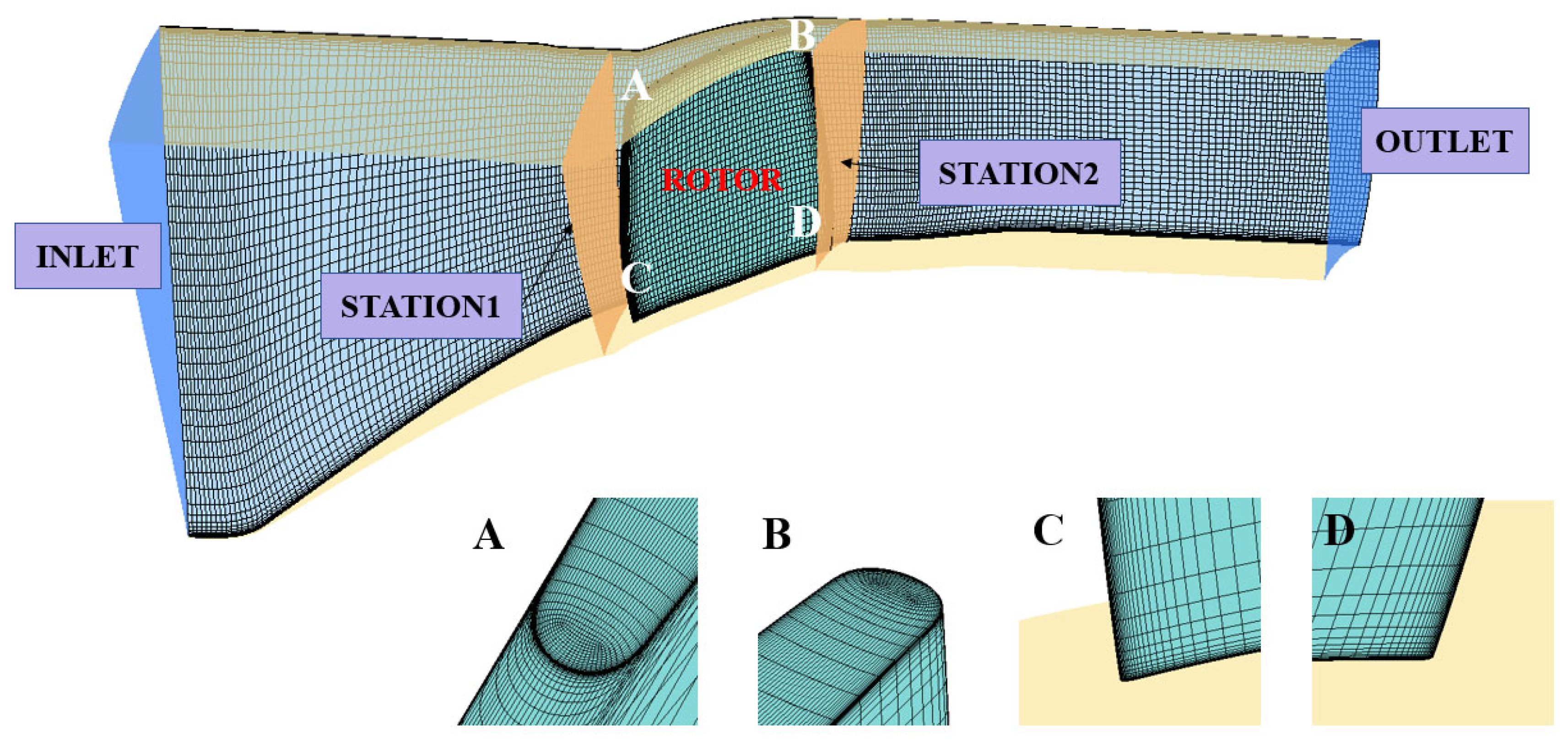
In this paper, the commercial CFD software NUMECA 17.1and ANSYS CFX 2024 R2 are used to simulate the single channel steady and unsteady numerical simulation of the DTR compressor. The mesh topology of the computational domain is obtained according to the ‘H-O4H-H’ partitioning strategy, and the inlet and outlet channels are composed of ‘H’ topology. To ensure mesh quality around the blade leading and trailing edges, an O-type mesh is employed to surround the blade [13]. The first-layer grid thickness is set to 1.0 × 10⁻⁶ m to accurately capture the near-wall flow, ensuring that the near-wall y+ value is less than 1. The final computational mesh used in this study is shown in Figure 1.
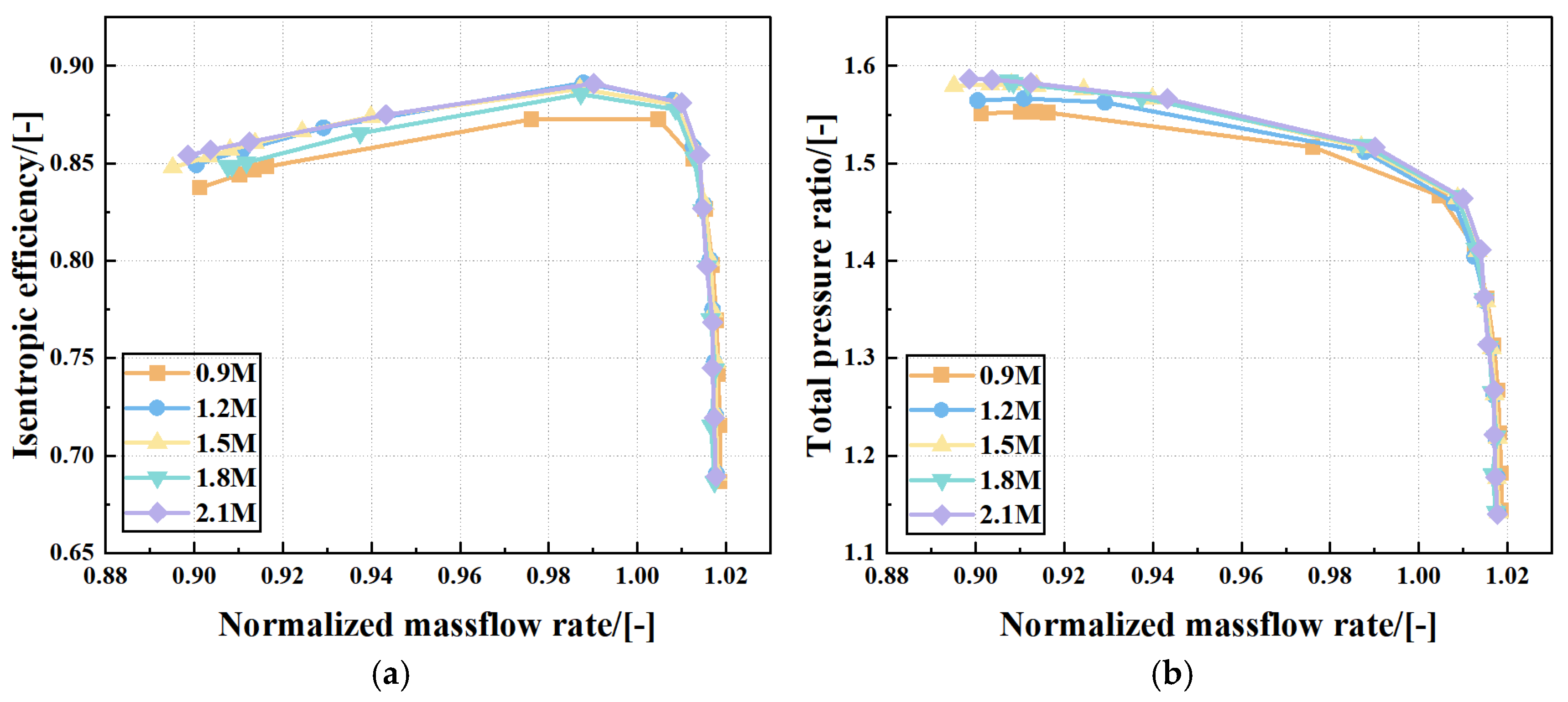
As shown in Figure 2, grid independence validation was performed using the SST model. Five grid resolutions were examined, with mesh counts of 0.9 million, 1.2 million, 1.5 million, 1.8 million, and 2.1 million. As shown, beyond 1.5 million cells, the total pressure ratio and peak efficiency exhibit no further notable improvement, confirming grid independence. Therefore, a grid count of 1.5 million is adopted for the simulations in this study.

2.3. Grid Independence Study and Turbulence Model Validation

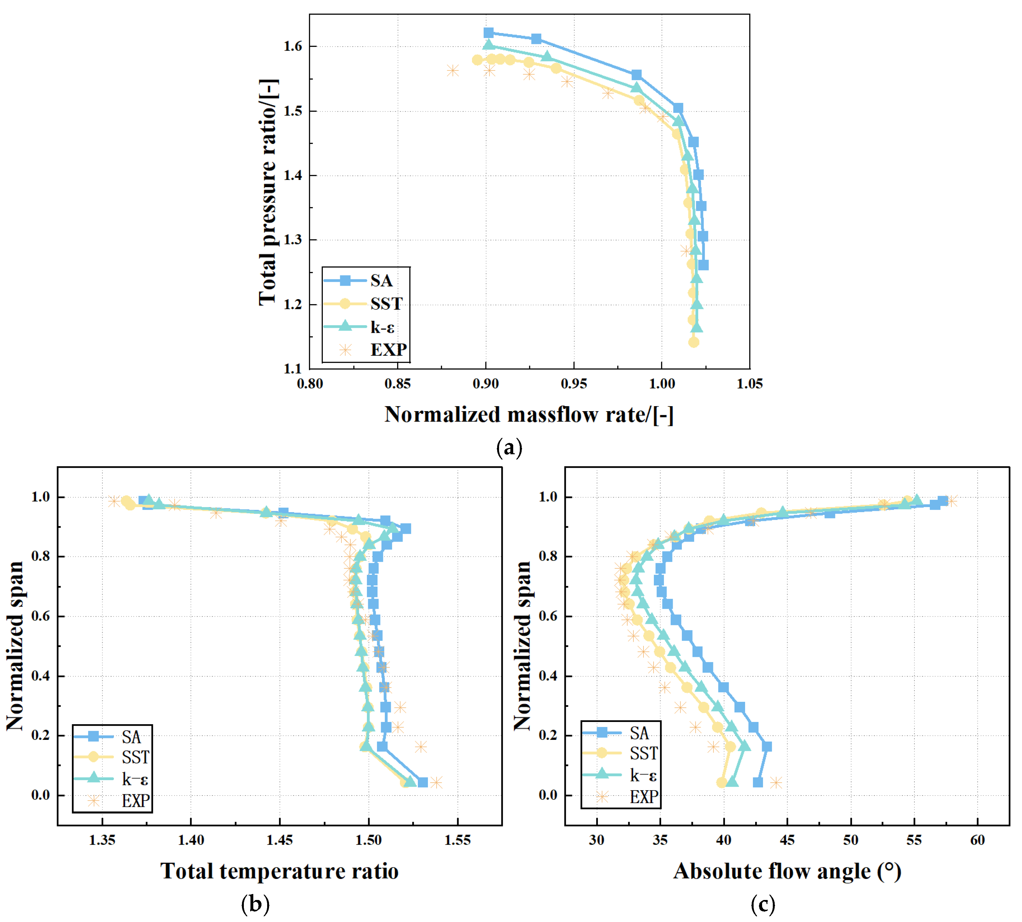
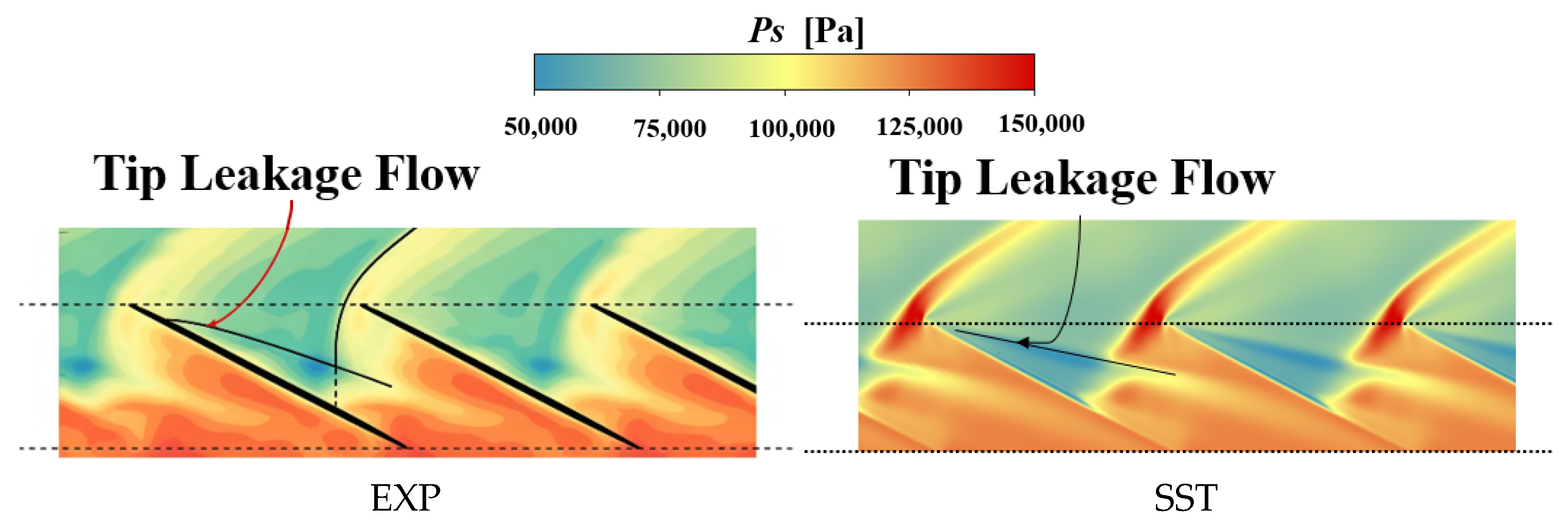
To reduce the impact of turbulence model choice on results, three widely used models (S-A, SST, and k-ε) were compared for their capability in predicting compressor performance. Figure 3 shows the pressure ratio–mass flow characteristic curves under different turbulence models, as well as the spanwise distributions of total pressure ratio and absolute flow angle at the peak-efficiency condition. It can be observed that the pressure ratio and mass flow rate predicted by the SST model agree better with experimental results, with a relative difference of 2.3% in pressure ratio. Figure 4 compares the static pressure contour predicted by the SST model with the experimental contour. The agreement is reasonably good. Therefore, the SST turbulence model is selected for all subsequent numerical simulations in this study.
To ensure data authenticity and reliability, the locations of the measurement planes at the passage outlet and inlet are set to match exactly those in the experiment. The inlet boundary condition is specified as a total temperature of 288.15 K and a total pressure of one standard atmosphere (101,325 Pa). The outlet boundary condition is defined as a gradient-averaged static pressure. All solid walls are assigned a no-slip boundary condition, and a high-order, high-accuracy discretization scheme is adopted. For the unsteady simulations, the physical time step is set to 1.25 × 10⁻⁵ s, with seven sub-iterations per physical time step.

3. Stall Mechanism of the DTR Transonic Compressor

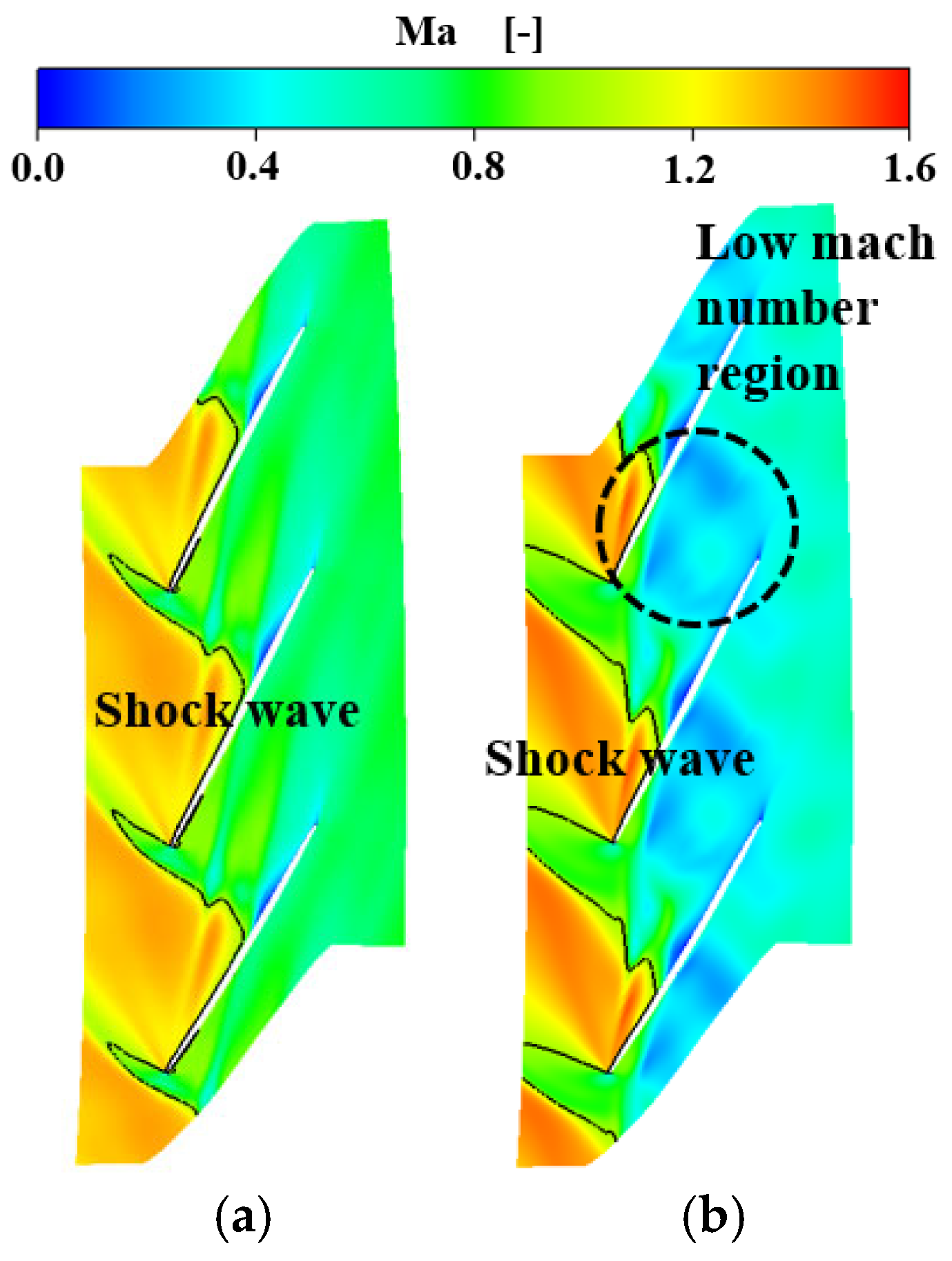
Figure 5 presents the relative Mach number contours at 99% span. At peak efficiency, the tip flow is well behaved, and a distinct shock wave is visible at the passage inlet. Under near-stall conditions, by contrast, the passage shock moves upstream and becomes a detached shock. From peak efficiency to near-stall operation, the low-Mach-number region induced by tip leakage vortex and suction surface boundary layer separation expands, signifying intensified vortex breakdown and boundary layer separation. Compared to the peak-efficiency point, the low-velocity region resulting from the interaction between the tip leakage vortex and the shock wave is considerably larger at near-stall. This region, along with the low-velocity zone caused by suction surface boundary layer separation, severely compromises the flow capacity of the leading edge passage. As the flow rate continues to decrease, the flow blockage intensifies progressively, eventually triggering stall.
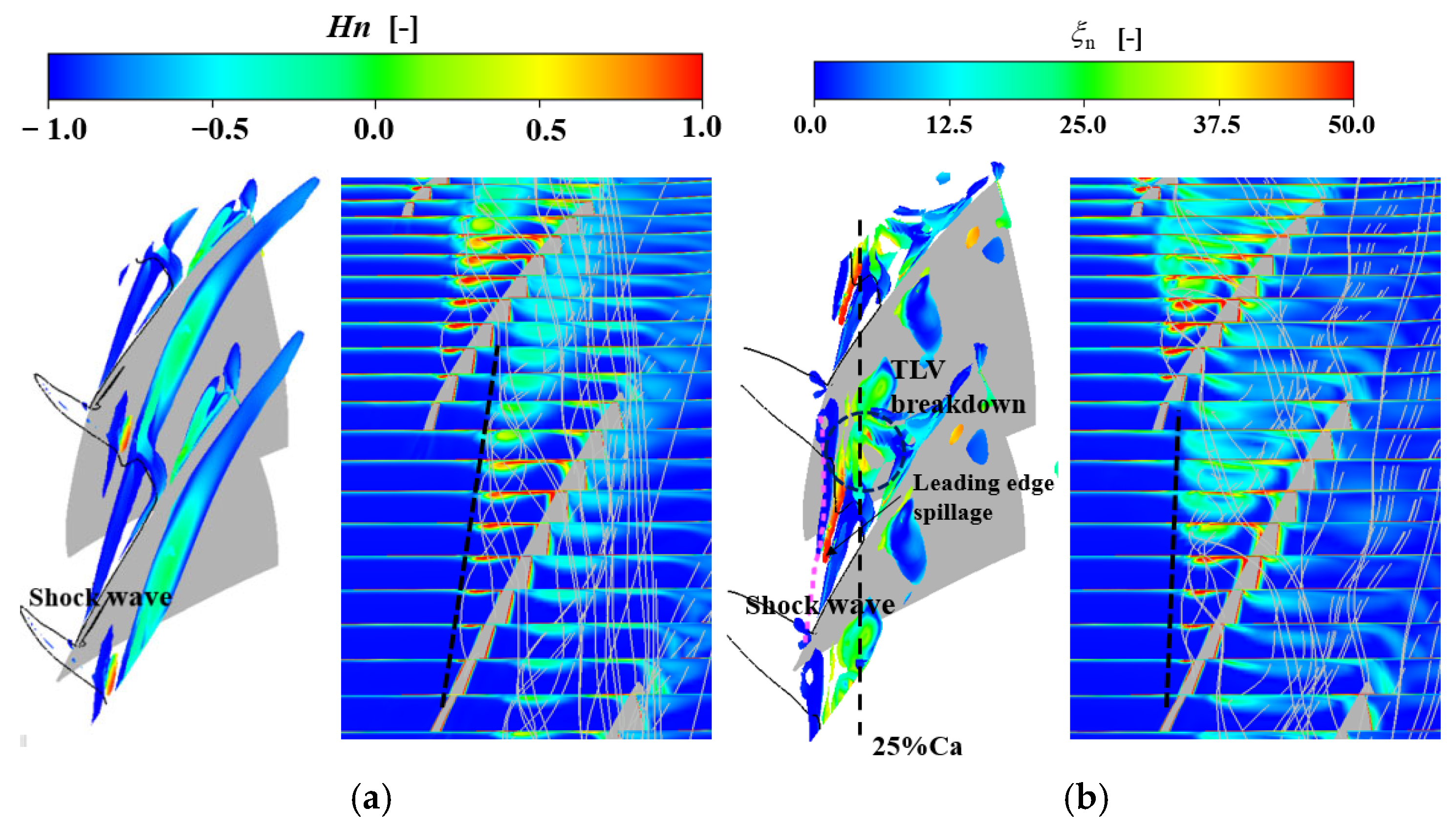
Figure 6 illustrates the tip leakage vortex structure visualized via the Lambda-2 criterion, with the shock wave indicated by a solid black line. Five streamwise cross-sections along the leakage vortex are also presented, colored by dimensionless vorticity. Under near-stall conditions, the leakage vortex interacts with the detached shock wave at the blade leading edge, resulting in vortex–shock interaction. After passing through the shock wave, the vortex core expands abruptly and undergoes a certain degree of twisting near the leading edge. Concurrently, the vorticity inside the leakage vortex dissipates, and the normalized helicity H n along the vortex core line changes from +1 to −1. It can therefore be concluded that the tip leakage vortex undergoes breakdown under near-stall conditions. As clearly shown in Figure 6, the breakdown region corresponds to the green area in the contour, which identifies the core region of vortex breakdown near 25% axial chord. Additionally, other vortex structures emerge in the middle-rear part of the blade passage. Low-velocity blockage emerges near the pressure side of the adjacent blade, leading to a sharp decline in flow capacity in the tip region. The presence of such complex flow structures indicates that the flow environment is considerably more severe than that at the peak-efficiency condition.
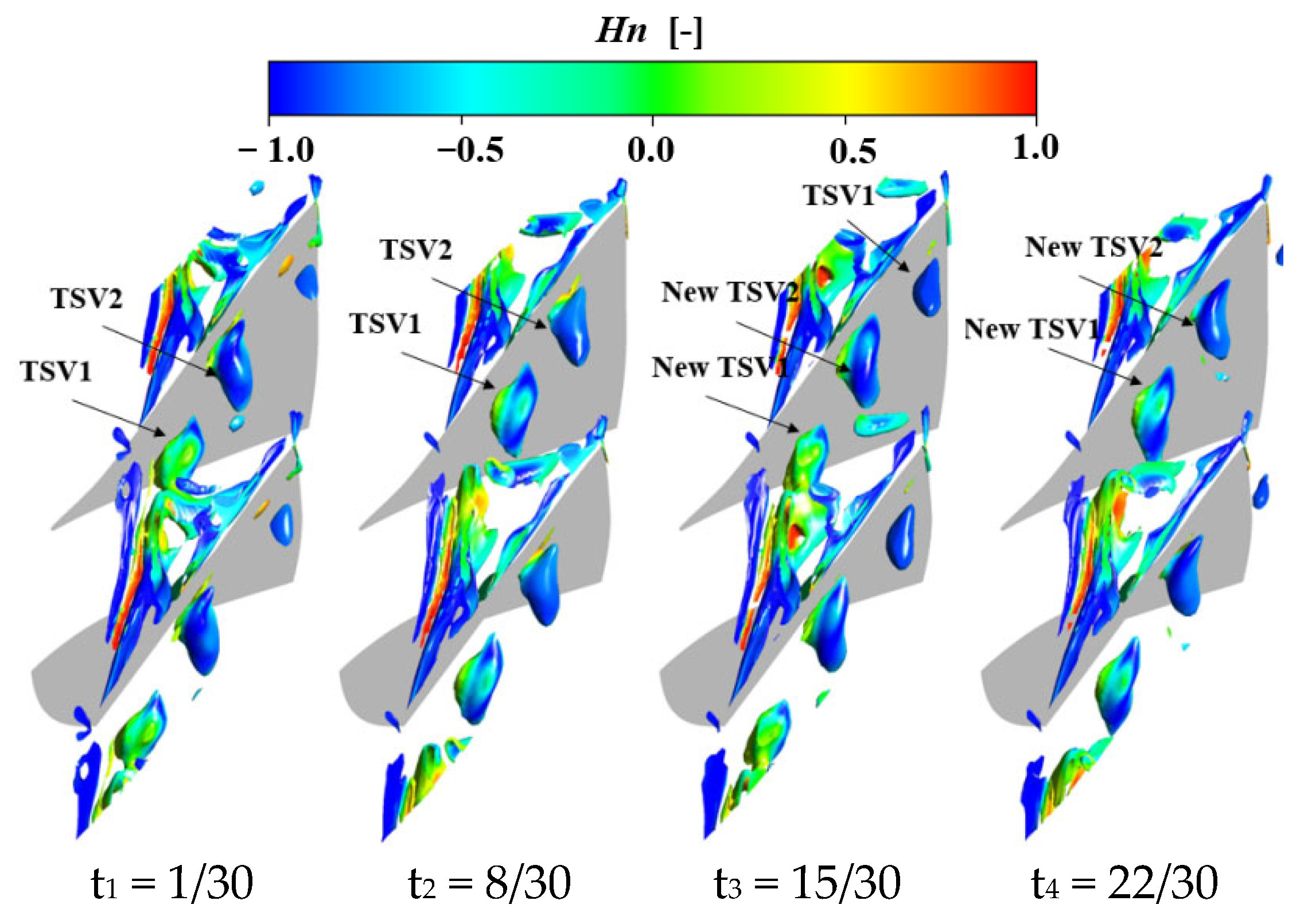
Figure 7 illustrates the vortex structures in the tip region over one period under near-stall conditions. It can be observed that the leakage vortex undergoes intense breakdown near 25% C a x , with two breakdown events occurring within a single period. Specifically, during the interval from t1 to t3, the first breakdown takes place. From t3 to t1 of the next cycle, a second breakdown occurs, repeating the previous process. Each breakdown generates a substantial recirculation zone. The shedding of each recirculation zone creates a pressure gradient that drives the circumferential migration of the tip secondary vortex, affecting the adjacent blade. At certain moments, the recirculation zone spans the middle of the passage, obstructing the mainstream flow, reducing the flow capacity in the tip region, and eventually triggering compressor stall.

4. Results

4.1. Endwall Synthetic Jet Design

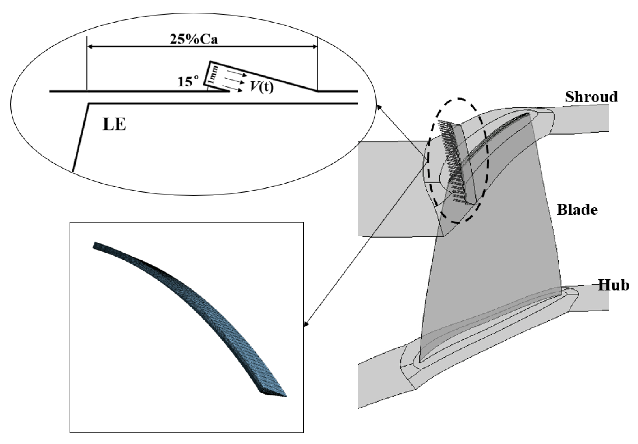
To control tip leakage vortex breakdown and the resulting blockage, thereby improving compressor stability, synthetic jets are deployed near the endwall. Based on previous findings [30,31], the jet slot height and width are both set to 1 mm, with a circumferential coverage ratio of 100% and an injection angle of 15°. The slot mesh is generated using IGG, with 49 nodes in the circumferential direction and 29 nodes in both the streamwise and radial directions. The slot position is defined as the distance from the trailing edge of the slot to the blade tip leading edge, normalized by the axial chord length, as shown in Figure 8. The front and rear walls of the synthetic jet slot are set as adiabatic no-slip walls, while the slot top is specified as a velocity inlet to simulate the periodic suction and ejection process. The velocity waveform is expressed as follows:
V t = V max sin ( 2 π f t + φ )
To compare the overall performance of the baseline compressor and the compressor with synthetic jet excitation, the stability margin improvement Δ S M and the peak isentropic efficiency change Δ η are introduced as metrics. Their expressions are given as follows:
Δ S M = π S J π S W N S × m S W m S J N S 1 × 100 %
In the equations, the subscript “SJ” denotes the synthetic jet, “SW” denotes the smooth-wall casing, “PE” indicates the peak-efficiency condition, and “NS” indicates the near-stall condition.
E = 0.5 ρ A 0.26 V max 3
ρ denotes the air density at the synthetic jet inlet; A represents the cross-sectional area of the synthetic jet inlet.
The calculation formula for compressor efficiency considering energy input of synthetic jets is
η = ( ( p 2 / p 1 ) ) ( ( γ 1 ) / γ ) 1 ) ( T 2 / T 1 1 ) + E / m / ( ( γ 1 ) / γ ) / R / T 1
where p 1 and p 2 are the average total pressures at the inlet and outlet measurement planes of the compressor, respectively; T 1 and T 2 are the corresponding average total temperatures; m denotes the compressor mass flow rate; E represents the additional energy input by synthetic jets; R is the gas constant; and γ stands for the adiabatic index of air.

4.2. Single-Slot Synthetic Jet

4.2.1. Effect of Jet Frequency on Compressor Performance

From the stall mechanism analysis of the baseline compressor, the location at 25% C a x corresponds exactly to the critical position where tip leakage vortex breakdown occurs, develops, and begins to form large-scale blockage. Therefore, the actuation position is fixed at 25% C a x . Intervening with a synthetic jet at this location can suppress the vortex breakdown at its source, reduce the extent of the low-velocity blockage region, and lower the channel blockage coefficient and entropy generation, without disrupting the flow structure in the mainstream.
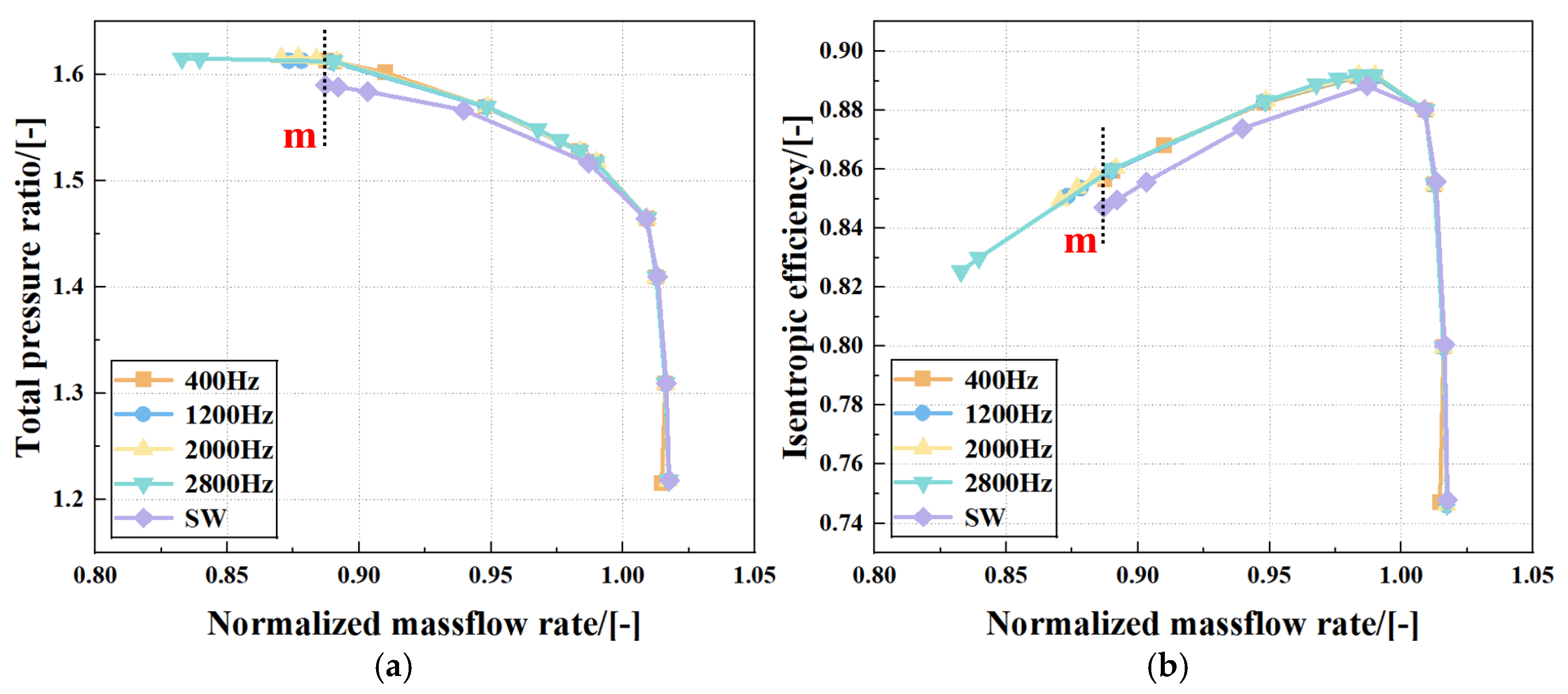
In this section, the peak jet velocity is kept constant at 100 m/s, and four typical excitation frequencies, namely 400 Hz, 1200 Hz, 2000 Hz, and 2800 Hz, are selected for numerical investigation. Figure 9 presents the overall compressor performance curves under different synthetic jet frequencies. Across the full operating range, performance curves for all frequency schemes align closely with the baseline near the design flow rate, with jet frequency inducing no significant fluctuations in total pressure ratio or efficiency. In the low-flow, near-stall region, however, the control effectiveness of the different frequencies begins to diverge. In the baseline compressor, tip leakage vortex breakdown induces passage blockage. With the actuation of synthetic jet, the mass flow rate at near-stall conditions shifts toward lower values, and the improvement-of-stability margin becomes more pronounced as the excitation frequency increases. When the excitation frequency is set to 2800 Hz, the mass flow rate at near-stall reaches its lowest point, and the enhancement of the stability margin reaches its maximum—there is a positive correlation between the excitation frequency and the improvement of stall margin.
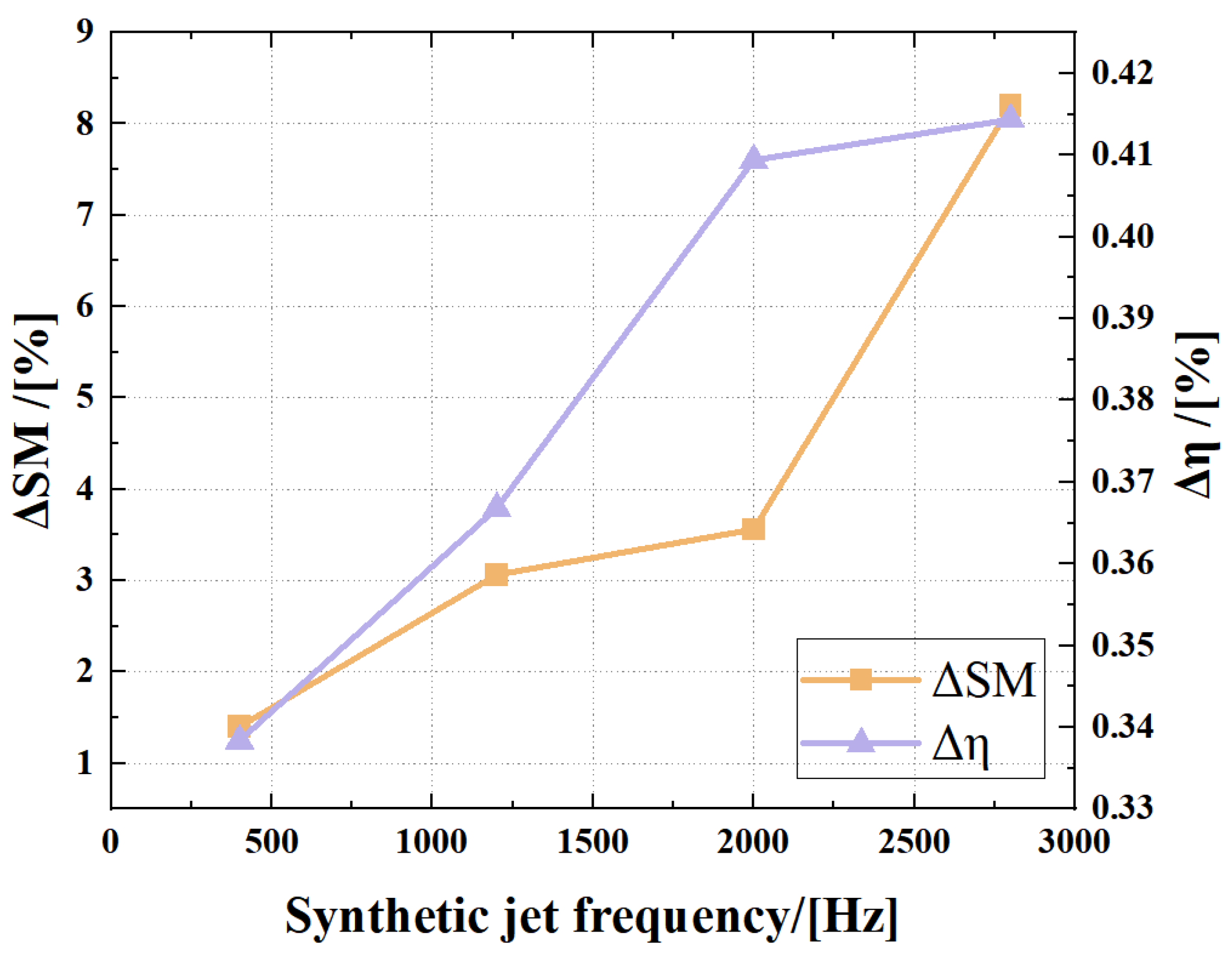
To quantify the improvements in the stability margin and isentropic efficiency achieved at different synthetic jet frequencies, Figure 10 presents the increments of the stability margin and isentropic efficiency relative to the baseline compressor for each frequency. It is evident that both performance increments increase monotonically with the rise of excitation frequency. As the highest frequency studied in this section, 2800 Hz has an optimal matching between the disturbance period and the unsteady shedding period of the tip leakage vortex. The synthetic jet can implement the blowing–suction intervention at the moment of the leakage vortex breakdown, inhibit the formation of the low-speed blockage zone at the source, and finally achieve the peak of the stability margin and efficiency increment. This result also directly proves that the core role of the synthetic jet frequency is to regulate the time scale of the unsteady disturbance.
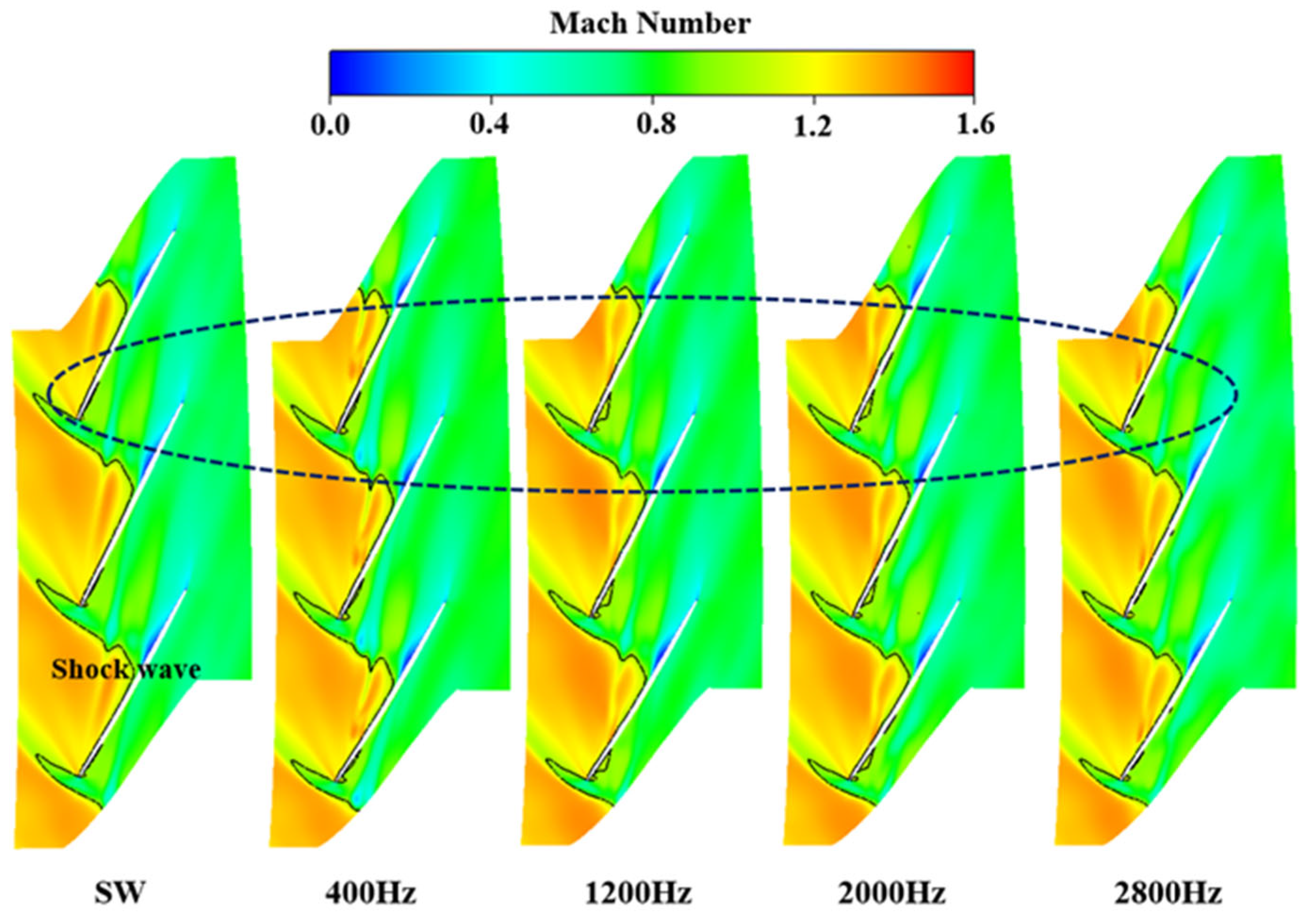
The Figure 11 shows contours of relative Mach number at 99% span under the peak-efficiency condition for synthetic jets with different excitation frequencies. It can be observed that synthetic jets of various frequencies have minor impacts on the tip flow field of the baseline compressor at the peak-efficiency condition. The flow-field structure remains basically consistent with that of the baseline compressor without obvious adverse disturbances, which indicates that the introduction of synthetic jets does not negatively affect the normal flow capacity of the compressor under the design-point condition, and favorable flow passage performance is maintained in the tip passage after control implementation. On this basis, the following section focuses on analyzing the flow-field regulation performance and underlying mechanism of synthetic jets under near-stall conditions.
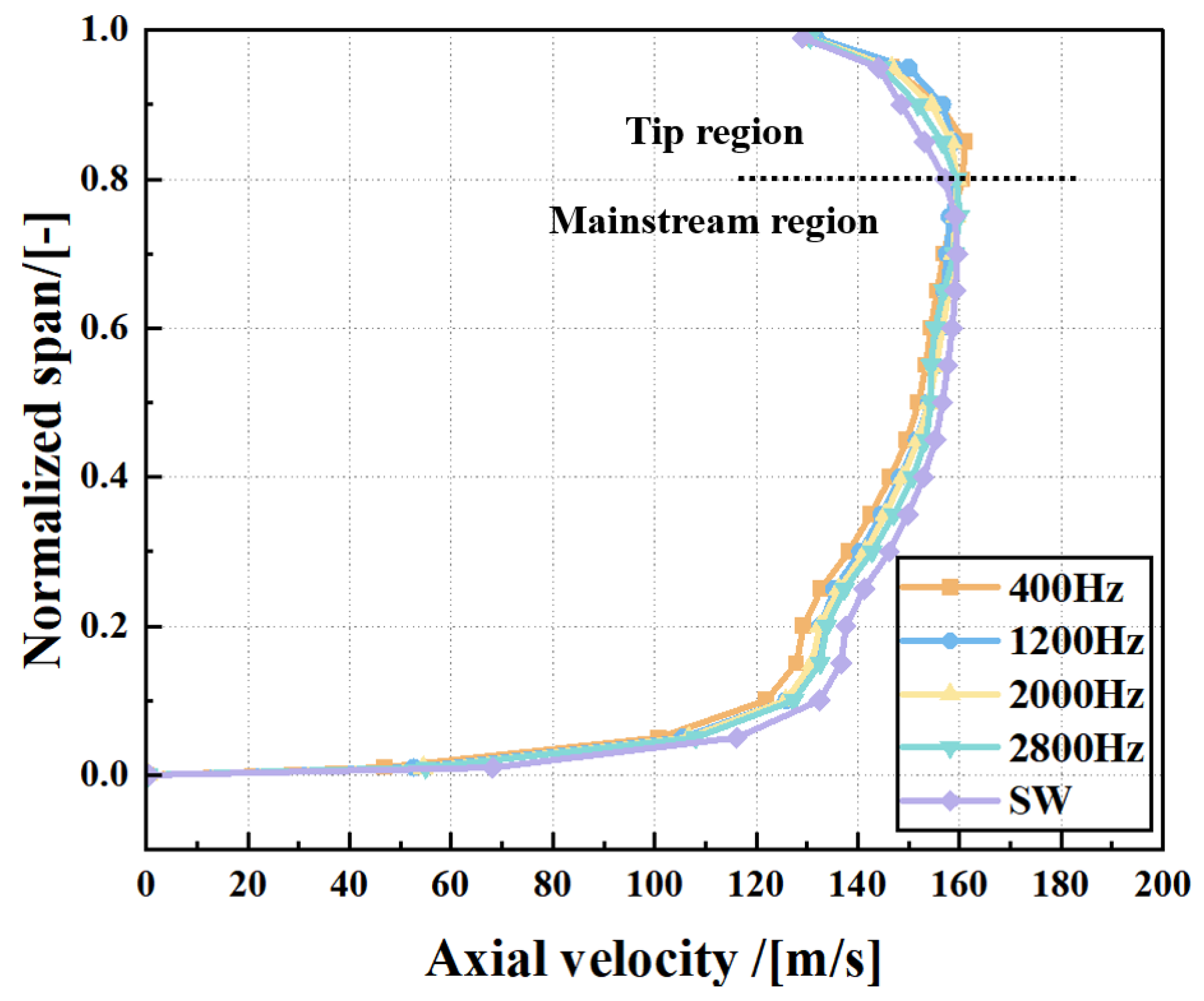
Figure 12 shows the distribution of the axial velocity of the compressor outlet section at near-stall operating point m along the blade height under the control of the prototype and four different frequency synthetic jets at the near-stall condition of the prototype. After the synthetic jet is applied, the distribution of the axial velocity of the flow field along the blade height shows a regular change. In the mainstream work area below 80% blade height, the axial velocity is lower than that of the prototype, and the lower the frequency, the more the axial velocity decreases. In the near-tip region above 80% blade height, the axial velocity increases obviously, and the lower the frequency is, the more the axial velocity increases. The axial velocity distribution under the excitation of 2800 Hz synthetic jet has the smallest difference with the prototype in the whole blade-height range. Under baseline near-stall conditions, the main flow region below 80% span serves as the core work-producing zone of the compressor. Meanwhile, the tip region above 80% span is prone to tip leakage vortex breakdown, passage blockage, and low-energy fluid accumulation—these issues are the root causes of flow instability, with the flow capacity reaching a marginal state. Low-frequency synthetic jets, due to poor unsteady matching with the tip leakage flow, tend to overcompensate when suppressing tip blockage: they excessively boost the axial velocity in the tip region while sharply reducing it in the main flow region. This trade-off between mainstream work capacity and tip-flow improvement ultimately limits the overall control effectiveness. In contrast, the 2800 Hz synthetic jet achieves good unsteady matching with the tip leakage flow. It suppresses leakage vortex breakdown and passage blockage, eliminates detrimental unsteady disturbances in the tip region, and preserves the work capability of the mainstream region to the greatest extent. Consequently, it achieves the largest stability margin and efficiency improvements with the least perturbation to the flow field.
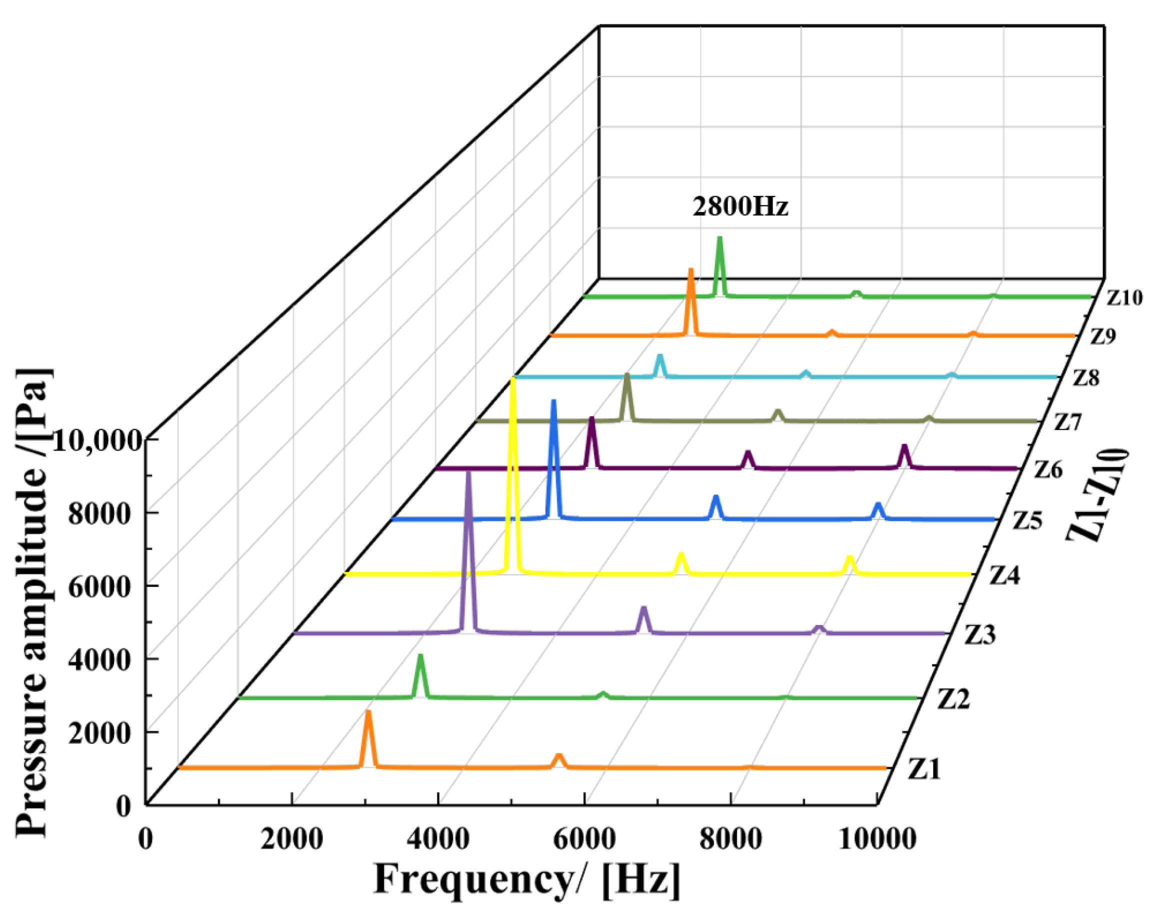
Considering the inherent unsteadiness of the synthetic jet and its effect on the tip flow, ten monitoring points were evenly spaced along the rotor suction surface near 99% span from the leading edge to the trailing edge during the calculation at the near-stall operating point m of the 2800 Hz synthetic jet scheme, in order to monitor static pressure variations. Fast Fourier transform (FFT) analysis of the signals from these pressure monitoring points was performed to obtain the frequency-domain characteristics of the tip region before and after synthetic jet excitation, as shown in Figure 13. FFT results show that synthetic jet actuation fundamentally alters the dominant frequency in the tip region. With the synthetic jet activated, the original dominant frequency of 6823 Hz in the tip region shifts to 2800 Hz, which exactly matches the excitation frequency of the synthetic jet itself. Under the smooth-wall casing condition without synthetic jet actuation, 6823 Hz is the dominant frequency of the tip flow, which arises from the unsteady self-excited effect of the leakage flow. Under the solid-casing condition without synthetic jet actuation, 6823 Hz is the dominant frequency of tip-region flow. This frequency originates from the unsteady self-excitation effect inherent to tip leakage flow. The unsteadiness of the compressor is mainly concentrated in the blade tip region and induced by tip leakage vortex breakdown. The breakdown of tip leakage vortex, together with the circumferential migration of tip secondary vortices and reverse-flow regions, causes periodic variations in tip loading, resulting in periodic fluctuations of tip leakage flow rate. These fluctuations in turn affect the intensity of tip leakage vortex breakdown, ultimately forming a self-sustained periodic unsteady flow process in the blade tip region. The intense fluctuations in tip static pressure likely cause blade loading variations, and once blade loading changes, the strength of the leakage flow is further affected, ultimately altering the overall intensity of the leakage vortex. The unsteady disturbances in the tip region are not uniformly distributed; their intensity is highest near the rotor leading edge and gradually decays toward the trailing edge along the blade. With synthetic jet actuation, the originally strong pressure fluctuation amplitudes in the tip flow field are effectively suppressed, and the dominant frequency in the tip region becomes 2800 Hz, consistent with the excitation frequency.
Observation of the FFT results reveals that the dominant frequency in the blade tip region undergoes a fundamental change after synthetic jet excitation. The original dominant frequency of 6823 Hz in the tip region shifts to 2800 Hz, which exactly matches the excitation frequency defined in the synthetic jet velocity formula. The 6823 Hz identified by FFT is the dominant high-frequency fluctuation induced by vortex–shock wave interaction after complete breakdown of the tip leakage vortex under near-stall conditions. By contrast, the optimal excitation frequency of 2800 Hz matches the natural instability frequency (shedding frequency) of the vortex before its critical breakdown. Active control requires early intervention in the precursor stage of vortex breakdown; hence, targeting the shedding frequency rather than the post-breakdown high-frequency fluctuation is the core reason for the optimal control performance achieved at 2800 Hz. As clearly shown in Figure 10, the growth rate of isentropic efficiency slows down when the jet frequency reaches 2800 Hz, and further increasing the frequency yields marginal performance improvements.
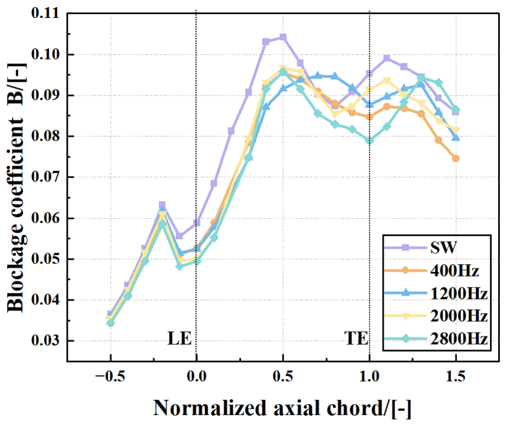
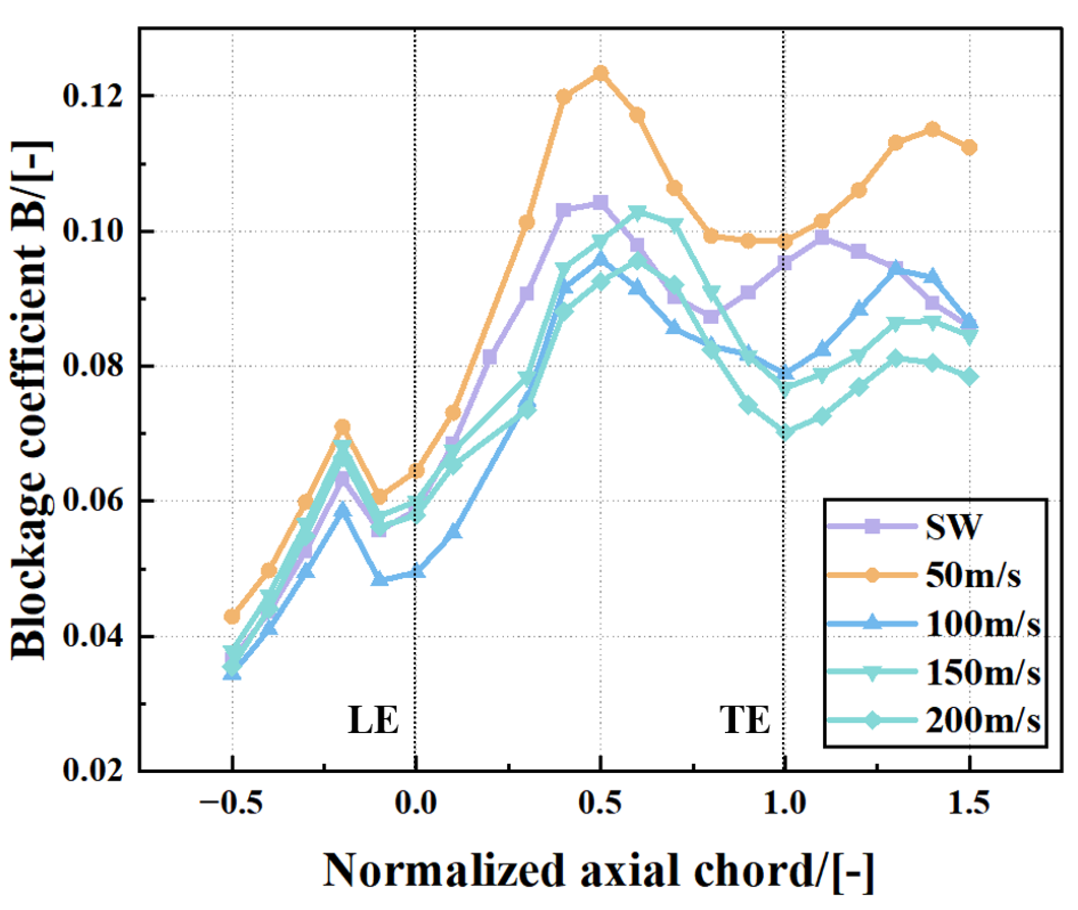
To quantitatively assess the ability of different synthetic jet frequencies to suppress tip passage blockage, Figure 14 presents the streamwise distribution of the tip blockage coefficient at the near-stall operating point m for the different schemes. The low-frequency synthetic jets at 400 Hz and 1200 Hz achieve only a slight reduction in the blockage coefficient, with the streamwise distribution remaining similar to that of the baseline compressor, indicating that flow conditions in the core blockage region are not effectively improved. In contrast, the high-frequency synthetic jet at 2800 Hz reduces the blockage coefficient to the lowest value among all schemes, quantitatively demonstrating that this frequency can continuously remove low-energy fluid from the tip region, eliminate the passage blockage bottleneck, and maximize the flow capacity in the tip region.
The blockage coefficient B characterizes the proportion of blocked area occupied by low-momentum fluid; a larger value of B means more severe blockage.
B = a 1 ρ W Z ρ W Z ¯ d σ S
where B is the blockage coefficient, a denotes the region where the mass flux is lower than the average mass flux, and S represents the cross-sectional area.
Based on the above analysis, within the parameter range examined in this section, 2800 Hz is identified as the optimal excitation frequency for the endwall synthetic jet. The core role of synthetic jet frequency is to regulate the time scale of unsteady perturbations. A higher frequency provides more timely actuation, enabling better matching with the unsteady evolution of the tip leakage vortex, thereby delaying vortex breakdown, reducing the low-velocity blockage region, and lowering passage blockage and energy losses. The optimal excitation frequency identified in this section lays a key unsteady parameter foundation for subsequent research on jet peak velocity and dual-slot synergistic control.

4.2.2. Effect of Peak Jet Velocity on Compressor Performance

Here, with the actuation position fixed at 25% C a x and excitation frequency held constant at 2800 Hz, four peak jet velocities (50 m/s, 100 m/s, 150 m/s, and 200 m/s) are analyzed comparatively. The influence of synthetic jet momentum intensity on the aerodynamic performance of the compressor rotor is analyzed, and the intrinsic relationship between peak velocity and tip flow-field control effectiveness is explored. The optimal peak velocity is identified, and the momentum-driven mechanism of stability enhancement and efficiency improvement is revealed, providing a reference for selecting appropriate jet momentum in engineering applications.
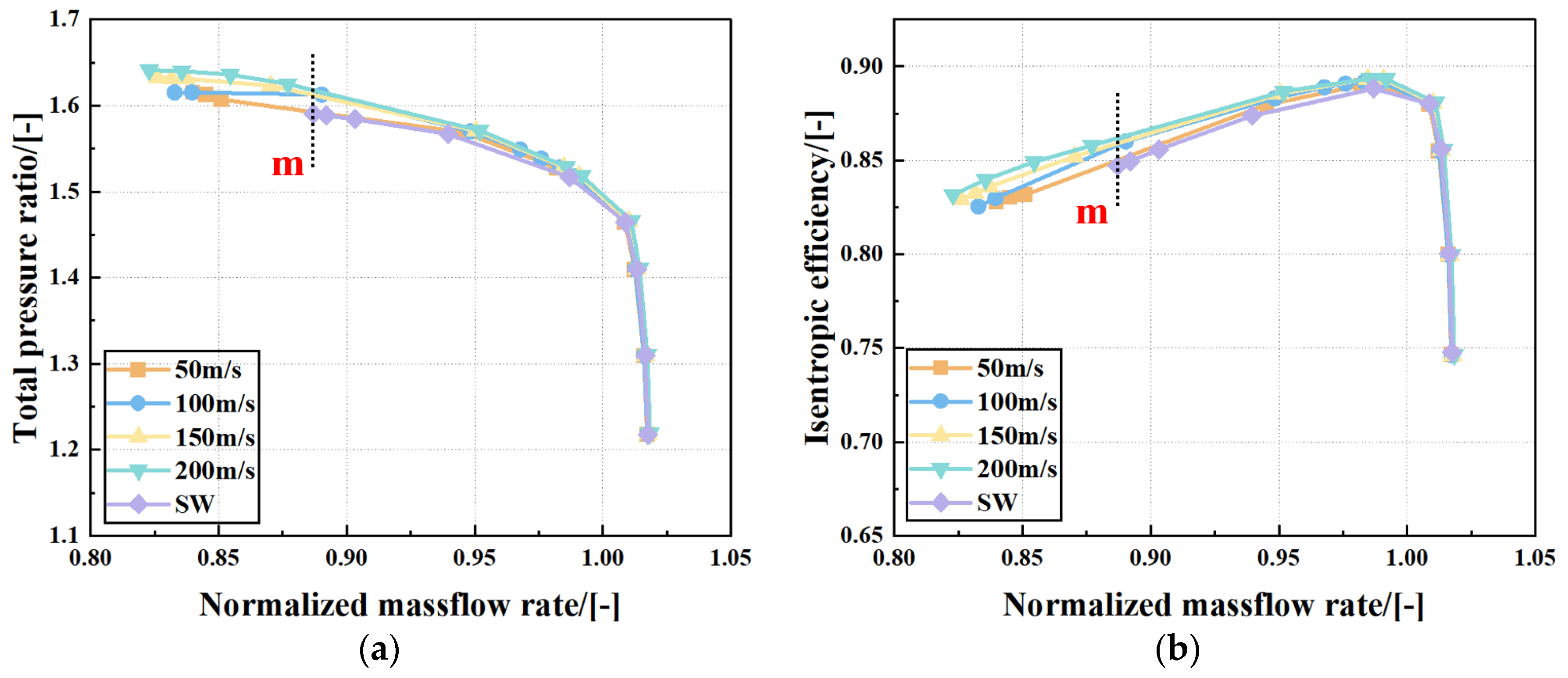
Figure 15 presents the overall compressor performance curves under different synthetic jet peak velocities. Over the entire operating range, the baseline compressor exhibits the largest near-stall mass flow rate. As the peak jet velocity increases, the extension of the compressor stability margin gradually enlarges, and the isentropic efficiency also improves. At the highest peak velocity of 200 m/s, the stable operating range of the compressor reaches its maximum, and the total pressure ratio and efficiency at the near-stall point are also the highest. The control effectiveness at the lowest peak velocity of 50 m/s is the weakest, with only a very limited efficiency improvement. The control effectiveness at 100 m/s and 150 m/s exhibits a stepwise increase, which clearly demonstrates a positive correlation between the momentum intensity of the synthetic jet and the enhancement of flow stability.
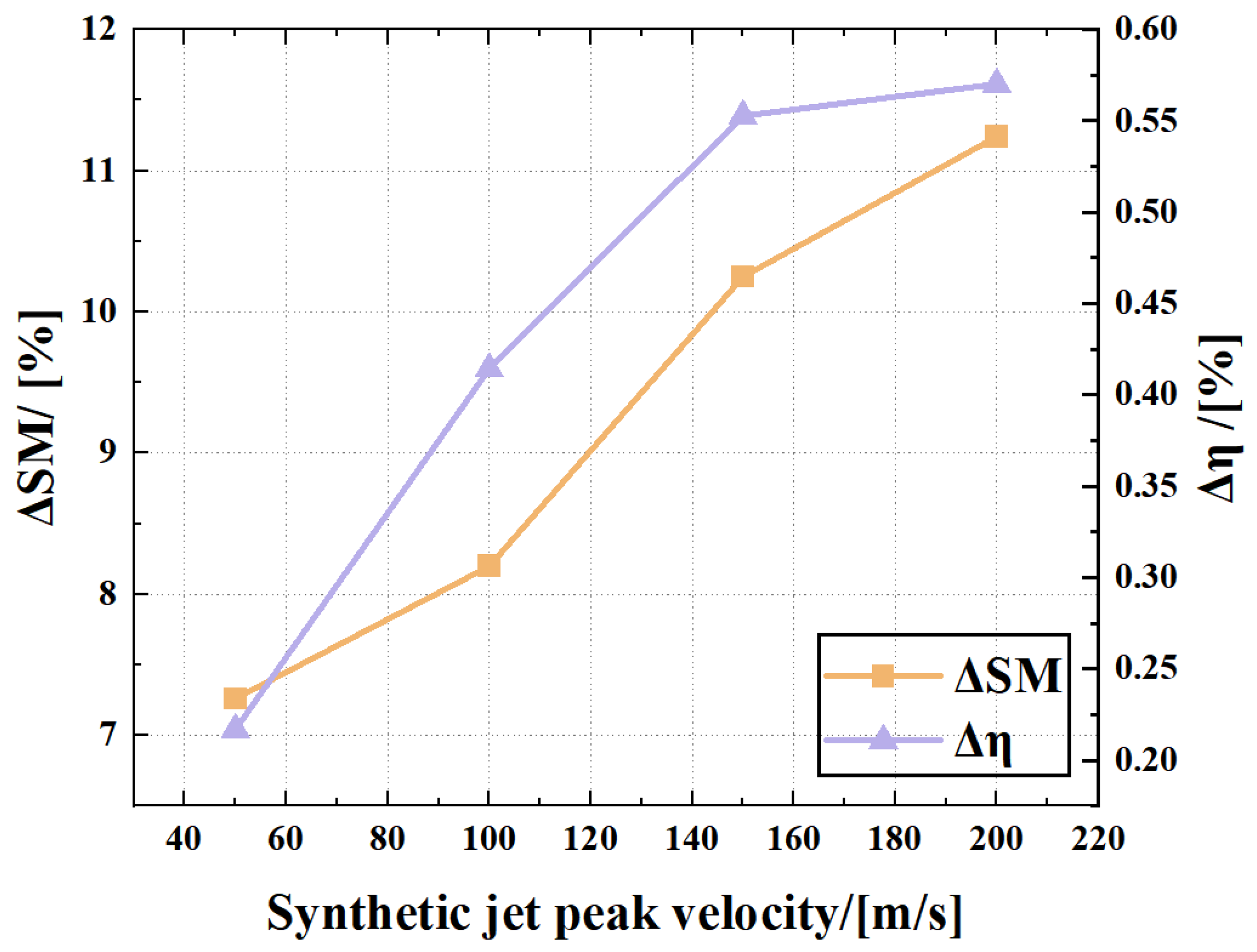
In order to more accurately quantify the control gain of synthetic jets with different peak velocities, Figure 16 shows the stability margin increment and isentropic efficiency increment of each scheme relative to the baseline compressor. Both performance increments increase steadily with the increase of jet peak velocity. At 200 m/s, both performance gains peak within the tested range, with a reduced growth rate, indicating notable momentum saturation. This characteristic also provides an important basis for avoiding excessive increase of synthetic jet momentum and reducing energy consumption of excitation system in engineering.
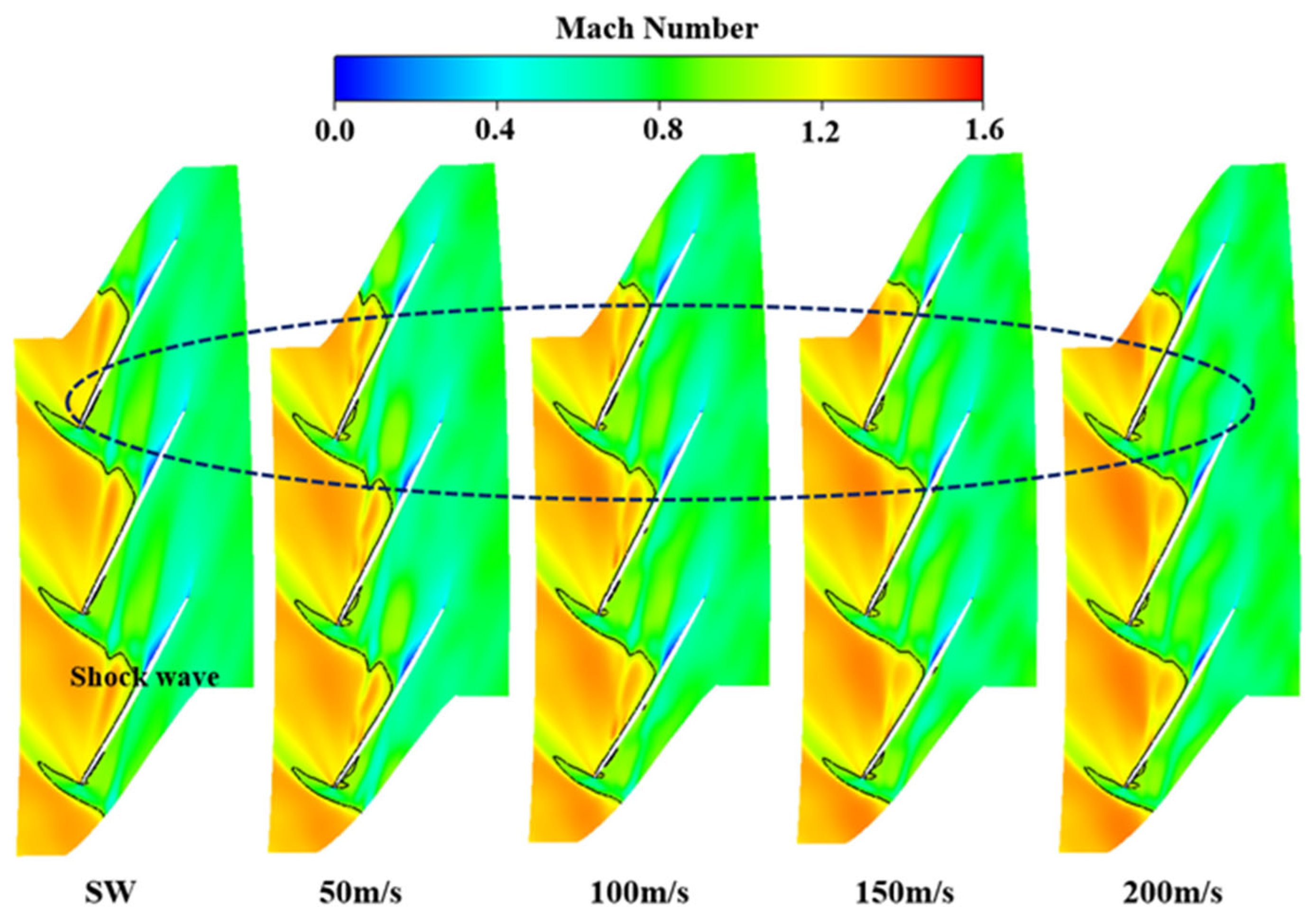
The Figure 17 shows contours of relative Mach number at 99% span under the peak-efficiency condition for synthetic jets with different peak velocities. It can be observed that under control schemes with various jet velocities, the shock wave morphology and distribution of low-Mach-number regions in the tip passage are consistent with those of the baseline compressor, with no obvious disturbance or deterioration in flow-field structure. This indicates that the introduction of synthetic jets does not exert adverse effects on the normal flow capacity of the compressor under the peak-efficiency condition, and favorable through-flow performance is maintained within the blade passage. It also verifies that the proposed control strategy can achieve stable regulation under near-stall conditions without compromising the performance at the design-point condition. The following section focuses on analyzing the regulation performance and underlying mechanism of different jet velocities on the flow field under near-stall conditions.
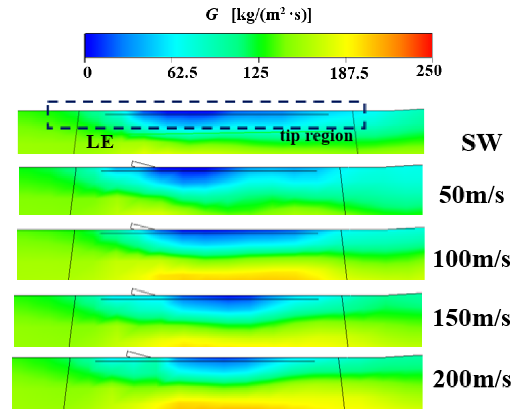
Figure 18 shows the meridional mass flux distribution at m point under different peak velocity synthetic jet excitation. Among them, the mass flux is defined as the product of density and relative axial velocity, and the area with a large decrease in the mass flux can be determined as the position where stall is prone to occur. Through comparison, it can be seen that the mass flux in the tip region is obviously improved after the synthetic jet is applied, which shows that the flow deterioration and loss are effectively alleviated after the synthetic jet is applied, and the stability margin and isentropic efficiency of the baseline compressor are expanded. The larger the peak velocity of the synthetic jet, the more the increase of the tip mass flux, and the better the excitation effect.
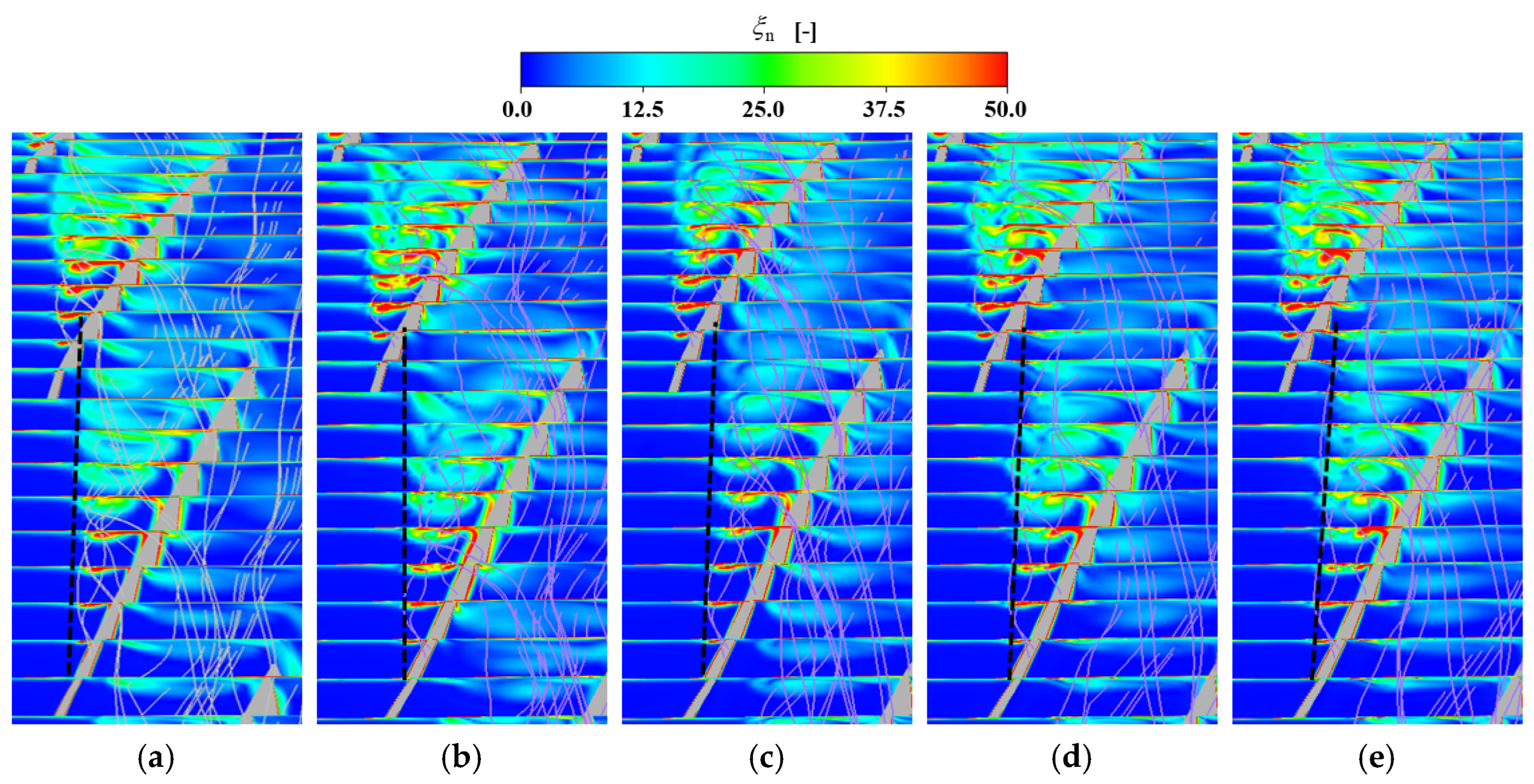
Figure 19 shows five streamwise cross-sections through the leakage vortex, which are colored using dimensionless vorticity. The dimensionless vorticity and streamline diagram of the flow section passing through the leakage vortex intuitively shows the regulation effect of the endwall synthetic jet with different peak velocities on the tip leakage vortex structure of the DTR compressor. Under the near-stall condition of the prototype, the vortex core of the leakage vortex presents a large-scale high vorticity concentration area, with a large structural scale and significant radial diffusion, which is the core cause of the blockage and flow instability of the tip channel. After the synthetic jet is applied, the vorticity distribution and structure of the leakage vortex are optimized. When the peak velocity reaches 200 m/s, the control effect is optimal, which effectively delays the occurrence of vortex breakdown. The position of the vortex core is further close to the suction surface, which reduces the blockage of the tip channel.
Figure 20 presents the streamwise distribution of the tip blockage coefficient, providing quantitative validation of the control effectiveness of different peak jet velocities. At a peak velocity of 50 m/s, the blockage coefficient is higher than that of the baseline compressor. As the peak velocity increases to 100 m/s, the blockage coefficient begins to fall below the baseline level. At a peak velocity of 200 m/s, the blockage is the lowest. This quantitatively demonstrates the strong correlation between peak jet velocity and the degree of tip blockage.

4.3. Dual-Slot Synthetic Jet

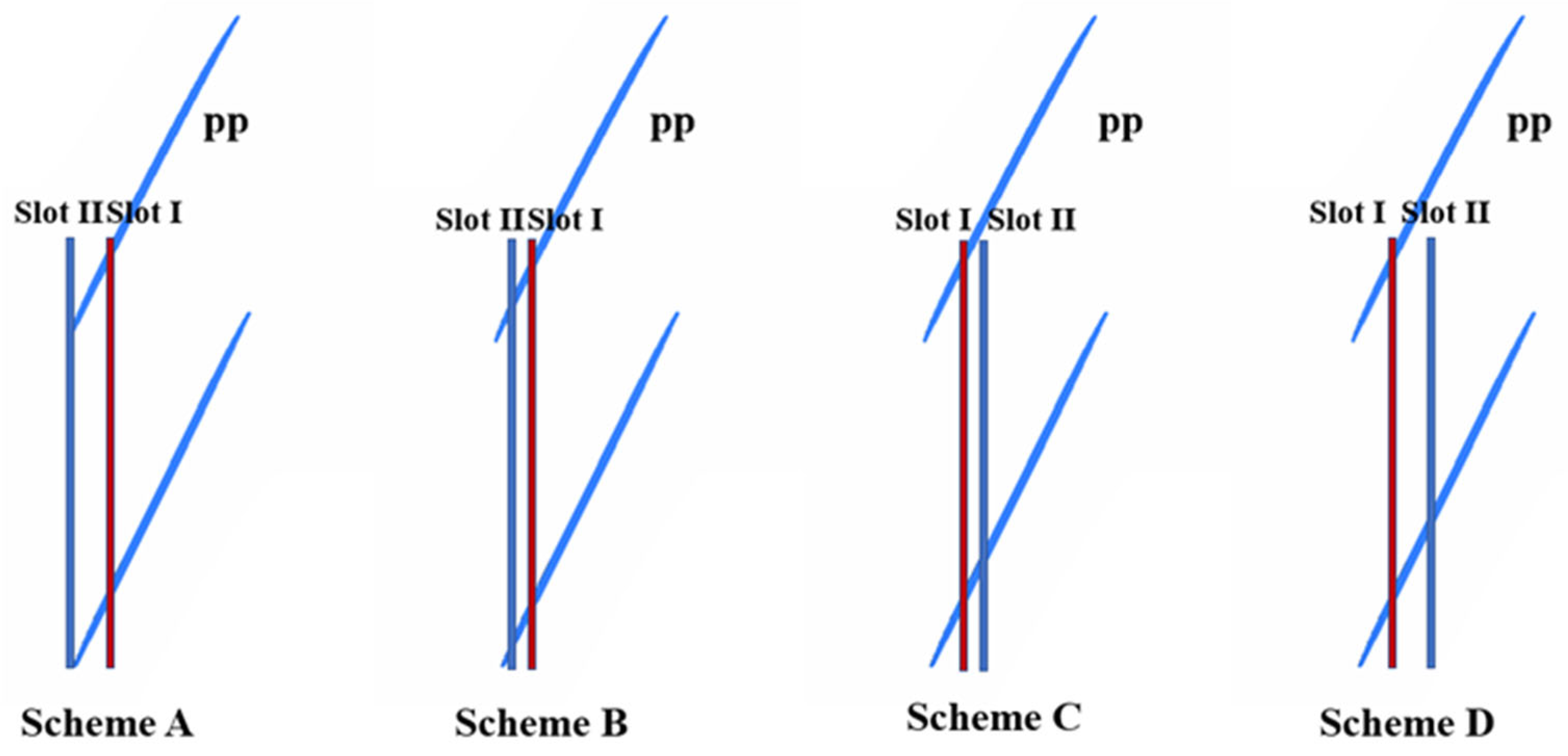
Based on the optimal single-slot synthetic jet parameters (excitation frequency of 2800 Hz, peak velocity of 200 m/s), this section investigates synergistic control using dual-slot endwall synthetic jets. Both slots are operated with the same synthetic jet parameters: a peak velocity of 200 m/s, an injection angle of 15°, and an excitation frequency of 2800 Hz. The front slot is assigned an initial phase angle of 0°, while the rear slot has an initial phase angle of 180°. One actuation position (Slot I) is fixed at 25% C a x , and the other actuation position (Slot II) is placed at different axial locations, namely 0% C a x , 12.5% C a x , 37.5% C a x , and 50% C a x . The effects of the dual-slot configurations on the aerodynamic performance of the compressor rotor are examined, and the control gains of the various dual-slot arrangements relative to the optimal single-slot scheme are compared. The optimal dual-slot configuration is identified, and the underlying synergistic mechanism of stability and efficiency enhancement by dual-slot synthetic jets is revealed. Detailed descriptions of the four schemes are given in Table 2, and Figure 21 presents their schematic diagrams.
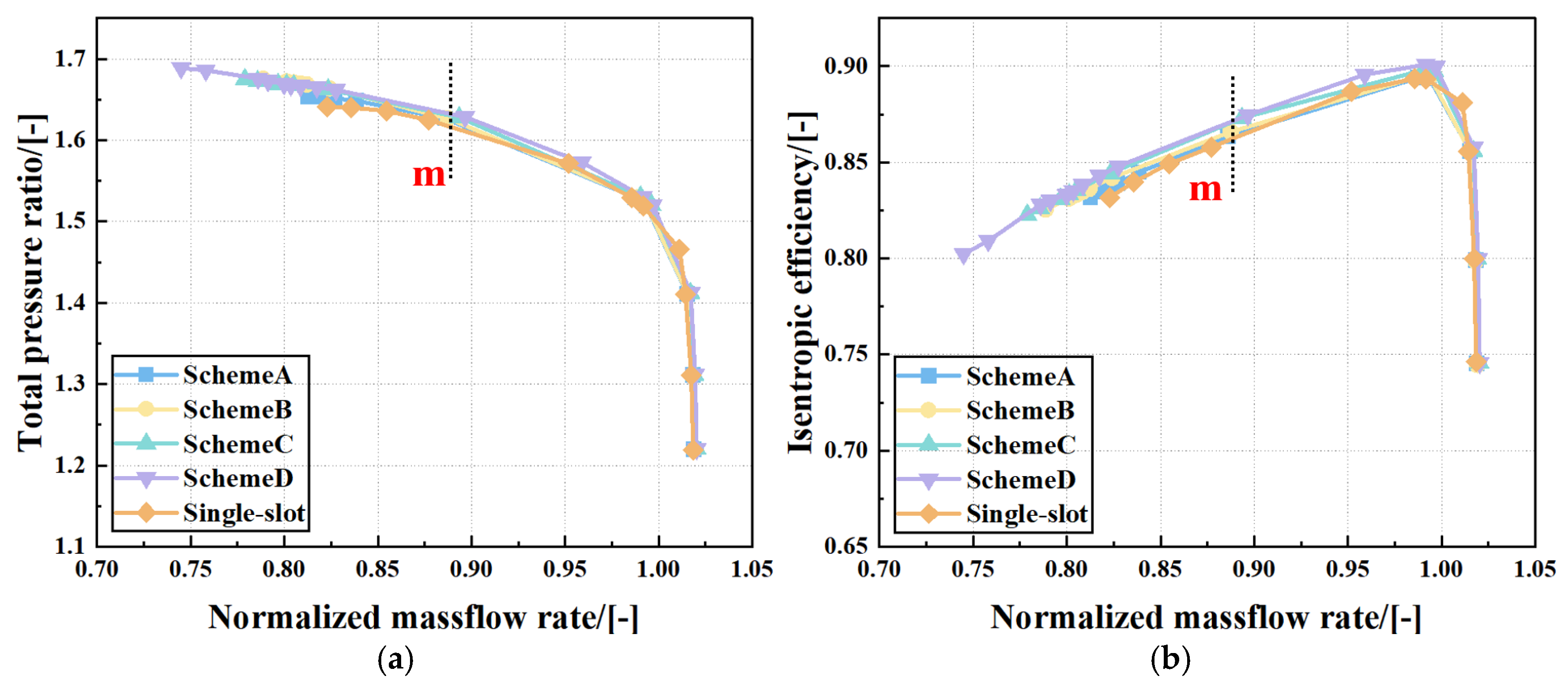
Figure 22 presents the overall compressor performance characteristic curves under different dual-slot synthetic jet configurations. All dual-slot schemes in this section are benchmarked against the optimal single-slot synthetic jet, rather than the baseline compressor. Over the entire operating range, the total pressure ratio and isentropic efficiency of the four dual-slot configurations are all superior to those of the single-slot scheme, with no performance degradation observed. This indicates that dual-slot cooperative actuation does not adversely affect the main flow region, and can further improve aerodynamic performance on the basis of the optimal single-slot control. As the operating point moves into the low-flow, near-stall region, the synergistic effect of the dual-slot synthetic jet becomes more pronounced with Slot II positioned closer to the trailing edge, and the stability margin and efficiency gradually increase. Cooperative regulation by the downstream slot replenishes momentum in the downstream breakdown region of the tip leakage vortex and suppresses the generation of secondary vortices after vortex breakdown. By alternately blowing and suctioning with a 180° phase difference relative to the upstream slot, it eliminates the accumulation of low-momentum fluid at the passage tail, reduces downstream entropy generation loss, and enhances full-path flow regulation. Among the schemes, Scheme D achieves the largest stable operating range and the greatest improvement in isentropic efficiency, demonstrating the best dual-slot synergistic control effect. The figure shows that both total pressure ratio and isentropic efficiency are improved.
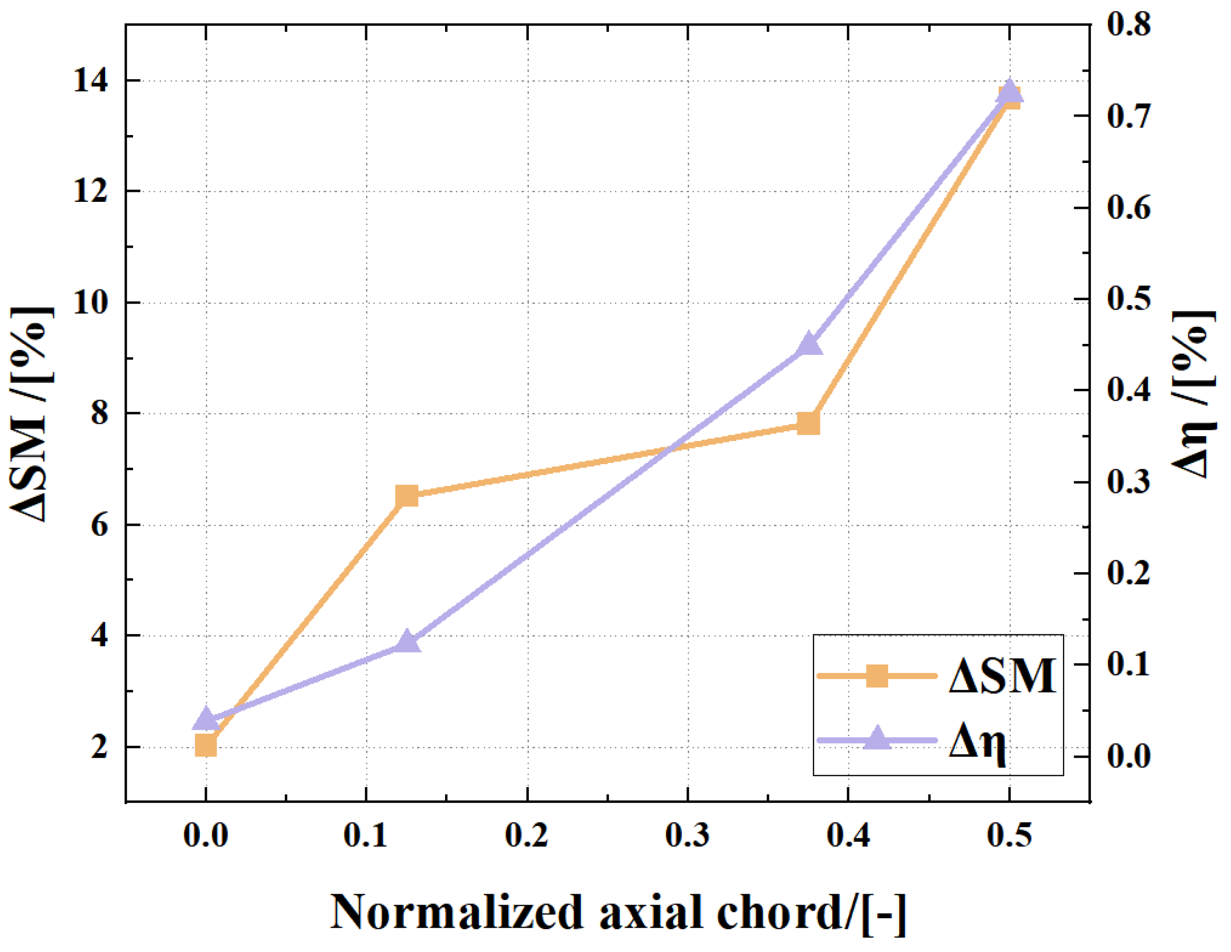
Figure 23 presents the stability margin improvement and isentropic efficiency improvement for each dual-slot configuration. Both improvements increase monotonically as Slot II moves further downstream along the axial direction, and all dual-slot configurations achieve positive gains, demonstrating that dual-slot synthetic jets can further exploit the potential of stability and efficiency enhancement through phase coordination between the front and rear actuations. In Scheme A, the effective regions of the front and rear synthetic jets overlap significantly, failing to generate a synergistic perturbation that covers the entire development path of the leakage flow. As a result, only a modest performance improvement is achieved compared with the single-slot scheme, and the synergistic effect remains unrealized. In Scheme B, the effective region of the synthetic jet begins to cover part of the leakage flow development path. The blowing and suction perturbations from the front and rear jets start to exhibit preliminary synergistic effects, leading to a significantly greater performance improvement than that of Scheme A. In Scheme C, the entire process of leakage flow generation, development, and transport is subject to staged control, with continuously reinforced synergy, resulting in substantially larger improvements in the stability margin and efficiency. In Scheme D, Slot I intervenes in the core region of leakage vortex generation, while Slot II applies terminus control to the downstream breakdown region of the leakage flow. With a 180° phase difference, the front and rear jets produce alternating blowing and suction, forming an unsteady synergistic perturbation that ultimately achieves the maximum performance gain relative to the single-slot synthetic jet.
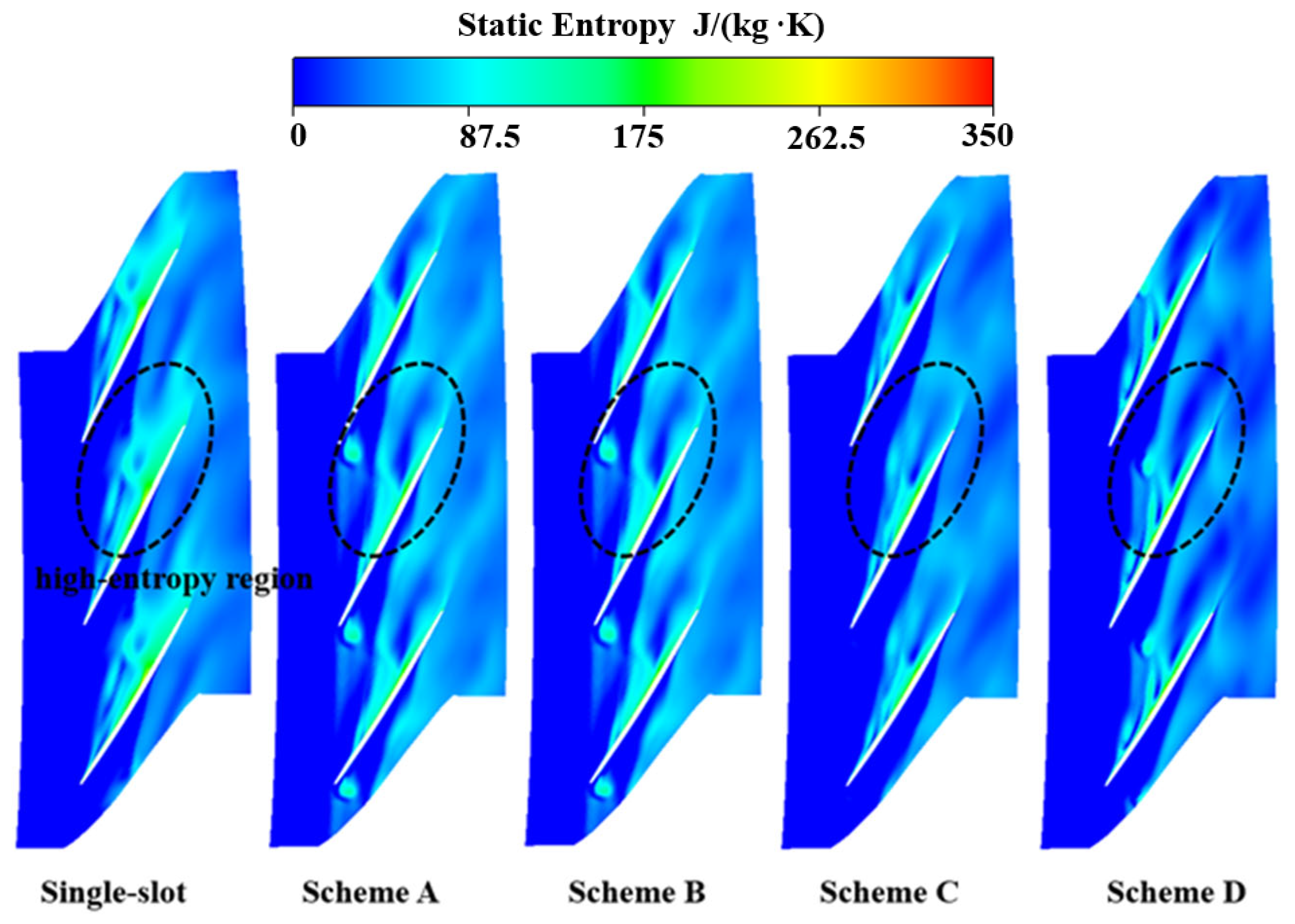
The Figure 24 shows static entropy contours corresponding to the single-slot scheme and various dual-slot synthetic jet schemes under the peak-efficiency condition, where high-entropy regions represent concentrated areas of flow loss. It can be observed that obvious high-loss regions still exist in the blade tip passage under the single-slot control scheme. As the position of Slot II in the dual-slot schemes moves toward the blade trailing edge, the range of high-entropy regions within the passage gradually shrinks with reduced flow loss, and flow loss in the main-flow passage is effectively suppressed. This indicates that the introduction of dual-slot synthetic jets can further improve the passage flow state and slightly enhance the aerodynamic efficiency of the compressor under the design-point peak-efficiency condition. Meanwhile, none of the dual-slot schemes introduce additional high-loss regions into the passage, verifying the adaptability of the proposed dual-slot synthetic jet control strategy under different operating conditions. The following section focuses on analyzing the flow-field regulation mechanism and instability suppression performance of different dual-slot schemes under near-stall conditions.
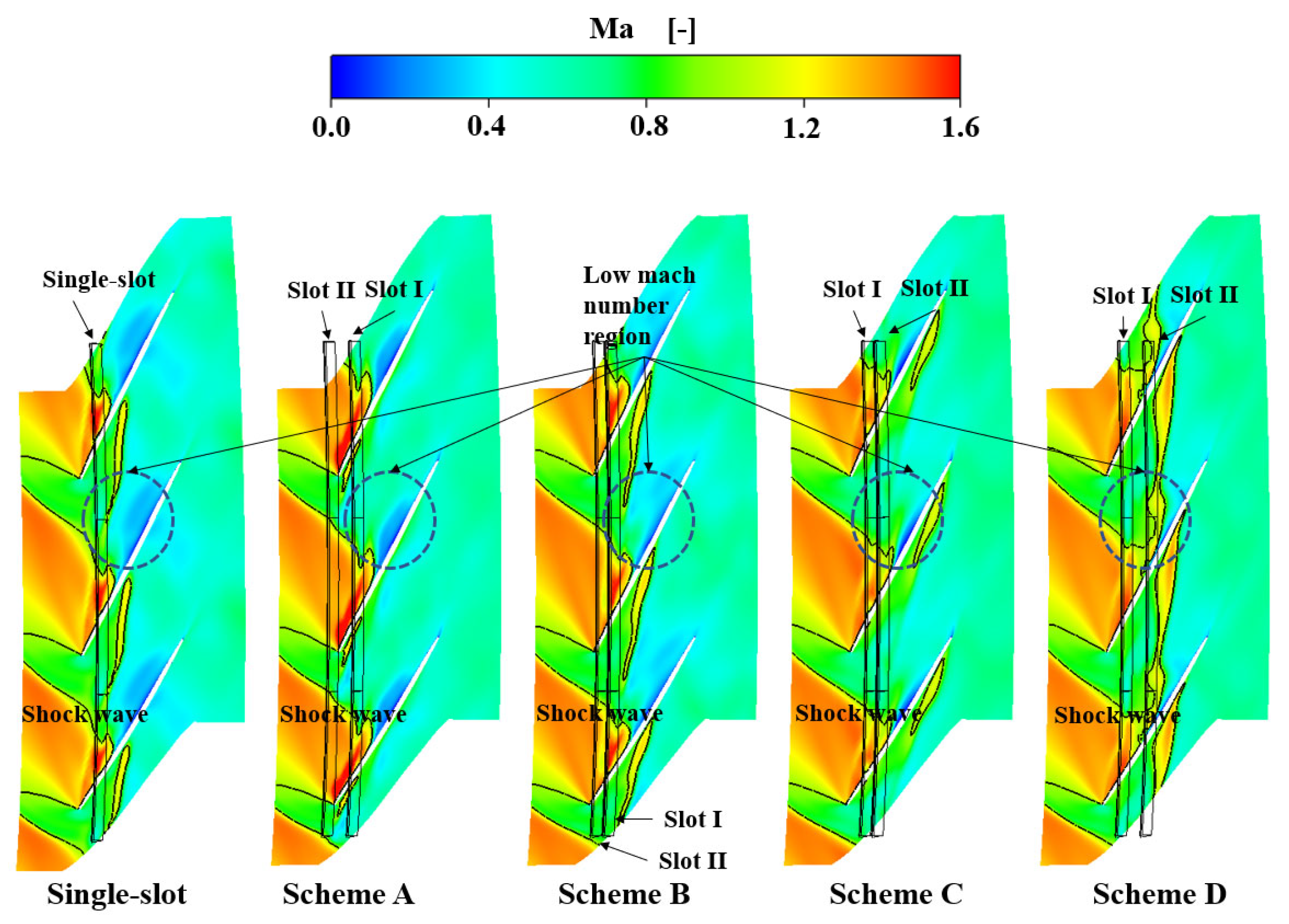
In Figure 25, the relative Mach number contours at 99% span under near-stall conditions intuitively illustrate the synergistic control effect of the dual-slot synthetic jets on the low-velocity blockage region in the tip region. With a single-slot synthetic jet, a small-scale low-velocity blockage region still exists at the tip, indicating that there is still room for further flow-field optimization. In Scheme A, the effective regions of the two slots overlap heavily, and the suppression of the blockage region is only marginally better than that of the single-slot scheme, with no substantial reduction in the extent of the blockage region. In Scheme B, the synergistic effect of the dual slots begins to emerge, the low-velocity blockage region is further reduced, and the proportion of the high-Mach-number mainstream region continues to increase. In Scheme C, the front and rear slots respectively intervene at different stages of leakage flow development; the low-velocity region is broken down into more scattered small patches, and the tip flow capacity is significantly improved. In Scheme D, the low-velocity blockage region at the tip is suppressed to the extent of nearly disappearing, and the entire passage is dominated by high-Mach-number mainstream throughout the unsteady cycle, achieving the optimal flow capacity.
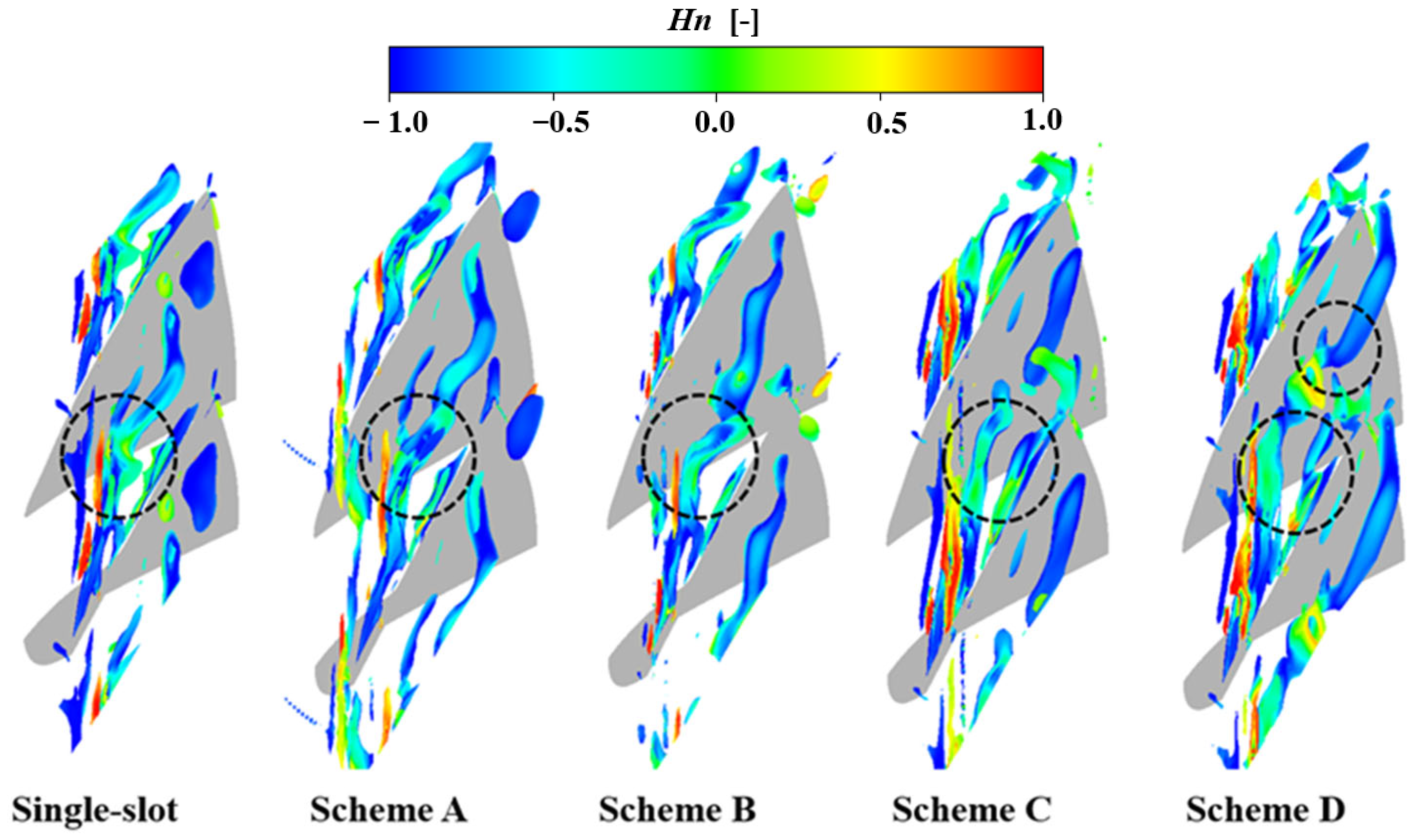
Figure 26 presents schematic diagrams of tip vortex structures under dual-slot synthetic jet excitation with different schemes, intuitively reflecting the cooperative control effect of dual-slot synthetic jets on tip leakage vortices. Under single-slot synthetic jet actuation, tip leakage vortex breakdown is delayed to a certain extent in the blade tip region. For Scheme A, the effective ranges of the two jets highly overlap, resulting in limited cooperative impacts on the leakage vortex; it further delays leakage vortex breakdown and slightly improves tip through-flow capacity. As the excitation position of Slot II moves downstream gradually, the upstream and downstream jets produce segmented unsteady disturbances that continuously act on the core region of leakage vortex breakdown, effectively delaying tip leakage vortex breakdown. In Scheme D, Slot I acts on the vortex breakdown region near 25% axial chord, while Slot II located at 50% axial chord continuously manipulates low-momentum fluid in the downstream area, which significantly enhances tip through-flow capacity. The dual-slot synthetic jets achieve the optimal cooperative suppression effect on leakage vortex breakdown.
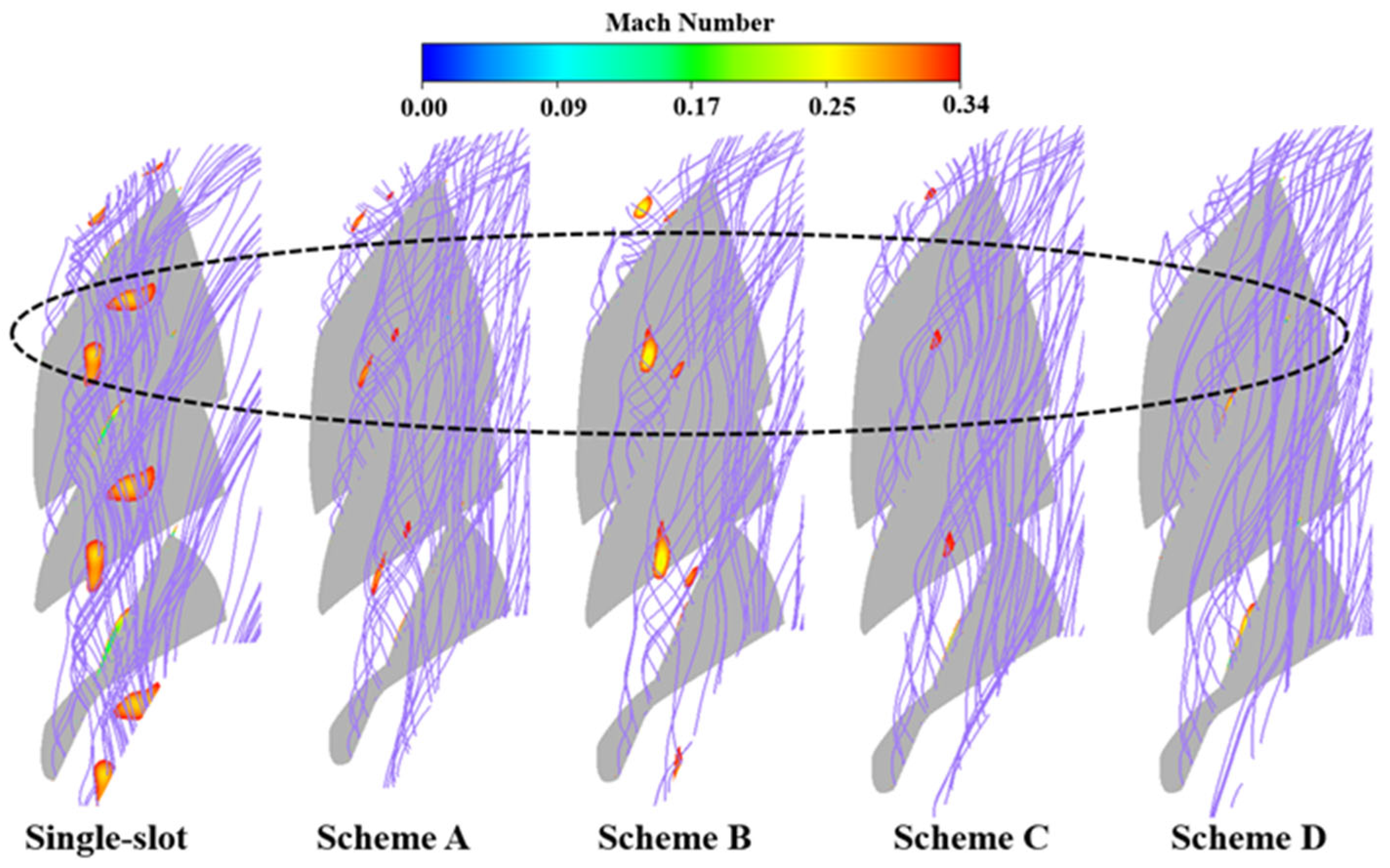
In Figure 27, local low-momentum fluid still exists under single-slot synthetic jet actuation, whereas the extent of low-momentum fluid is reduced in Scheme A. As Slot II moves downstream, the curling intensity of leakage streamlines and the coverage of low-momentum fluid decrease continuously. In Scheme D, the dual-slot jets scavenge most of the low-momentum fluid, yielding the optimal flow performance. The upstream and downstream actuators act on the initial development zone and downstream transport zone of leakage flow, respectively, realizing full-process cooperative regulation.
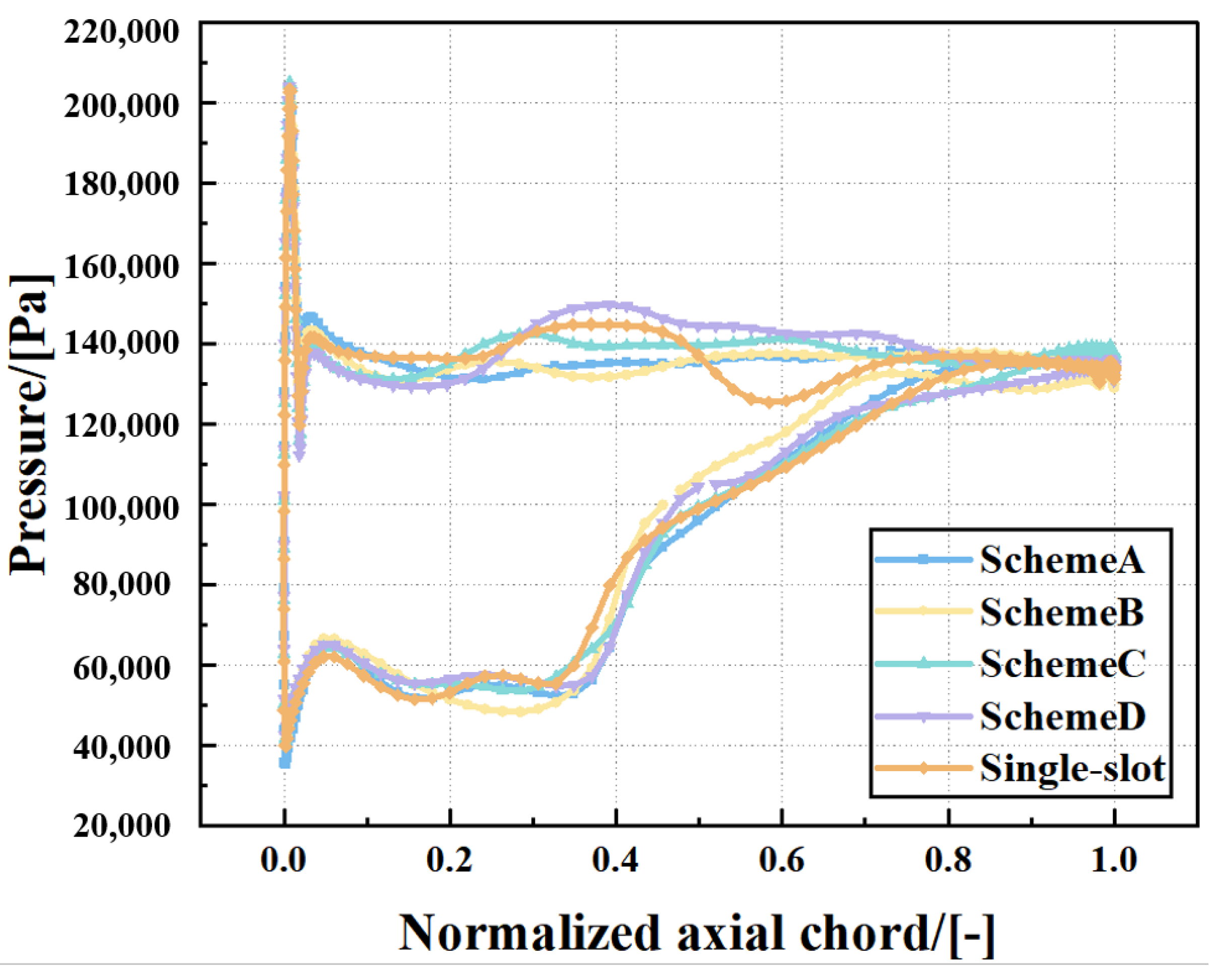
Figure 28 presents the distribution of tip loading along the axial chord for different dual-slot synthetic jet configurations. Compared to the single-slot synthetic jet scheme, the static pressure fluctuations on the pressure side become smoother after dual-slot actuation. It can be observed that the location of the first region with a large static pressure difference remains nearly unchanged, while the second region shifts axially downstream as Slot II is moved further downstream. This indicates that the onset of boundary layer separation on the suction side occurs later, thereby delaying tip leakage vortex breakdown.
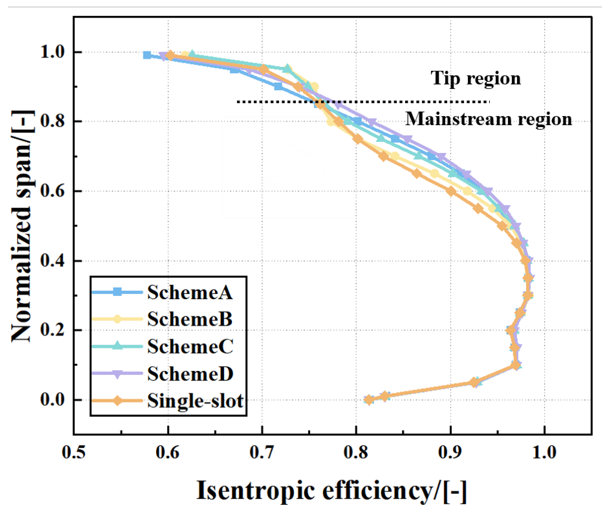
Figure 29 presents the spanwise distribution of isentropic efficiency under control of the dual-slot synthetic jets and the single-slot synthetic jet for the different configurations. Analysis of the four dual-slot schemes reveals that below 80% span, all dual-slot configurations further improve the isentropic efficiency relative to the single-slot scheme, with Scheme D exhibiting the largest increase. In the near-tip region, Scheme D with dual-slot synthetic jets shows basically equivalent efficiency compared with the single-slot scheme. However, the efficiency gain below 80% span is more substantial. The mainstream region below 80% span is the core work-producing zone of the compressor, while the tip region above 80% span is where leakage vortex breakdown, passage blockage, and low-energy fluid accumulation occur, representing the root cause of instability; the flow capacity in this region is marginal. Although Schemes B and C improve isentropic efficiency above 80% span, their efficiency gains below 80% span are relatively small, not as large as those achieved by Scheme D. Scheme D trades off a small reduction in efficiency above 80% span for a larger improvement in mainstream efficiency below 80% span. On the premise that the efficiency in the blade tip region remains basically unchanged, this trade-off conforms to the design priorities of aero-engines. After the tip-region flow field is moderately improved, priority is given to enhancing main-flow efficiency. Simply pursuing efficiency gains only in the tip region, while ignoring the main-flow region yields inferior stall margin extension compared with Scheme D. As the tip region and main-flow region form a coupled integrated system, comprehensive evaluation is essential. Overall, Scheme D outperforms other schemes in improving compressor performance, achieving a final stall margin enhancement of 13.68%.
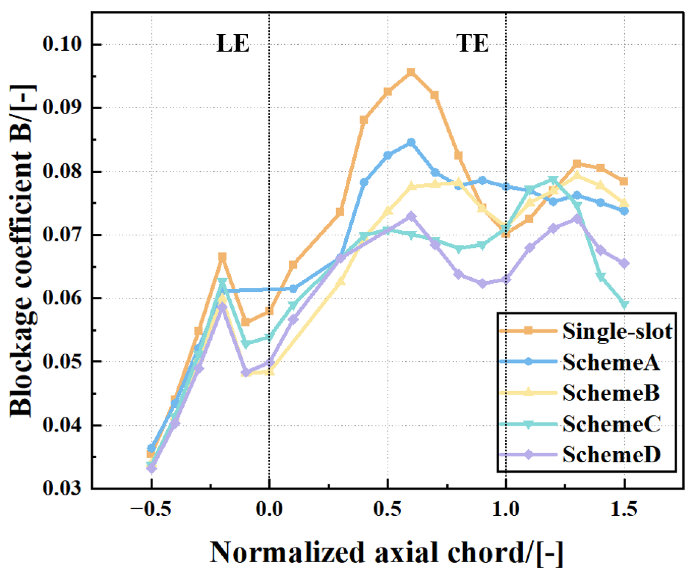
In Figure 30, the distribution curves of the blockage coefficient quantitatively confirm the synergistic improvement in tip passage blockage achieved by the dual-slot synthetic jets. With the single-slot configuration, low-energy fluid accumulation still persists, leaving room for further improvement in through-flow capacity. For Scheme D, the blockage coefficient is reduced to the lowest level across the entire axial chord range, with no pronounced local blockage peaks, quantitatively demonstrating that this dual-slot arrangement can eliminate tip passage blockage to the greatest extent and exhibits the most prominent quantified synergistic control effect.
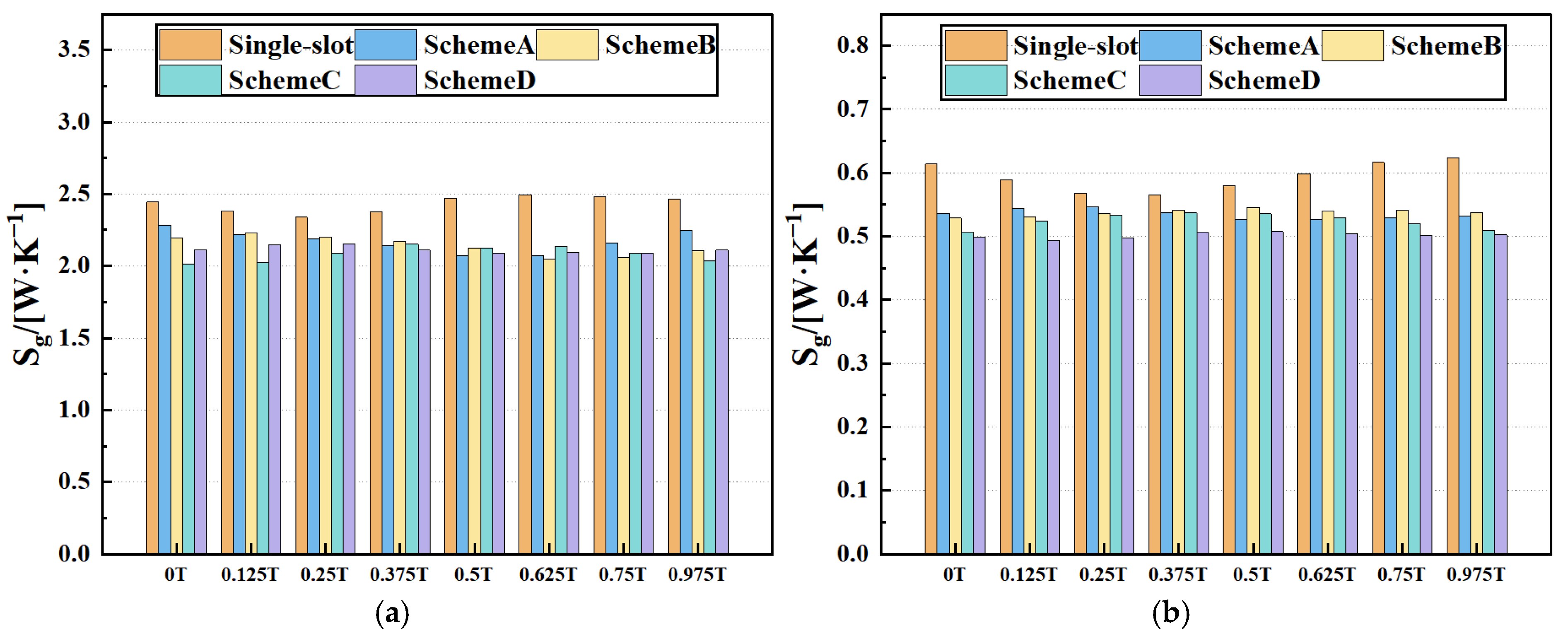
Figure 31 presents the variation of different loss components over one period for the single-slot synthetic jet and the various dual-slot configurations. Compared to the single-slot scheme, the dual-slot synthetic jets have almost no effect on the core loss and inlet loss of the compressor, but substantially reduce the tip leakage loss and outlet loss, with the most pronounced reduction observed in the tip leakage loss.
In the time domain evolution of the tip loss, the tip loss of the single-slot jet maintains the highest level in the whole cycle, corresponding to the persistent small-scale low-speed region and mixing loss. After the dual-slot jet is applied, the tip loss basically decreases with the backward movement of the slot II position. The action area of scheme A overlaps, and the tip loss is only slightly lower than that of the single-slot. The full-cycle loss level is still high, and the synergistic regulation effect is limited. The scheme B and scheme C are dual-slot into a jet to blow off and suck the low-energy fluid at the tip more thoroughly, and the peak and mean value of the tip loss continue to decrease; the tip loss of scheme D is at the lowest level of all schemes at some times; and the outlet loss is at the lowest level in the whole cycle, and the loss suppression effect is the best. The optimal mechanism of stability expansion and efficiency improvement of the scheme is verified from the energy level.
In summary, the dual-slot jet at the appropriate slot II position injects more momentum into the downstream of the fixed position than the single-slot jet, which reduces the downstream loss. This is the obvious advantage of the dual-slot jet relative to the single-slot jet. For the dual-slot jet, the influence of different slot II positions on the flow control of the dual-slot jet is mainly reflected in whether the downstream momentum distribution is effectively improved, thus affecting the final effect of flow control.

5. Conclusions

In this paper, the DTR transonic axial flow compressor is taken as the research object. The numerical simulation method is used to reveal the unsteady evolution law and stall induction mechanism of the tip leakage vortex under near-stall conditions. The active flow control of the endwall single-slot and dual-slot jet is studied, and the internal mechanism of the synthetic jet to suppress instability is revealed. The main conclusions are as follows:
  • For single-slot jets, excitation frequency and peak velocity both significantly affect stability improvement. When the slot is located at 25% axial chord length, it can accurately act on the core area of leakage vortex breakdown. When the excitation frequency is 2800 Hz, the high-frequency disturbance can match the time scale of unsteady tip flow, and the intervention timeliness is the strongest. When the peak speed is 200 m/s, it provides sufficient control strength, and further increases in velocity yield only marginal gains. Under the optimal parameter combination, the compressor stability margin is increased by 11.24%, and the design efficiency is increased by 0.57%.
  • The dual-slot jet relies on the spatial layout and the 180° phase difference to form a synergistic effect, and the control ability is better than that of the single-slot. When the slot I is at 25% axial chord length and the slot II is at 50% axial chord length, the front and rear synthetic jets can cover the full development path of the leakage flow in sections, inhibit the downstream breakup of the leakage vortex, further reduce the channel blockage, vortex strength and energy loss, and the stability margin and efficiency continue to increase by 13.68% and 0.72% on the basis of single-slot optimization.
  • The core mechanism of the synthetic jet is that the blowing stage divides the large-scale leakage vortex and blows away the low-energy blockage region; in the suction stage, fluid trapped in the tip clearance is extracted to prevent the low-energy fluid from gathering again. The whole process only acts on the tip region and does not interfere with the flow of the mainstream channel, so it will not reduce the rated performance. The findings clearly determine the optimal configurations for single-slot and dual-slot jets, which can provide direct references for the engineering design of active flow control in transonic compressors. They also address practical challenges encountered in high-temperature and high-pressure compressor applications, such as high energy consumption of excitation systems and difficulty in identifying the optimal excitation position.

Author Contributions

Conceptualization, Q.W.; methodology, Q.W.; investigation, Q.W.; writing—original draft preparation, Q.W.; writing—review and editing, G.A.; supervision, G.A. All authors have read and agreed to the published version of the manuscript.

Funding

The authors would like to acknowledge the support of the Scientific Research Projects of Higher Education Institutions in Hebei Province (No. QN2025149).

Institutional Review Board Statement

Not applicable.

Informed Consent Statement

Not applicable.

Data Availability Statement

The data presented in this study are available on request from the corresponding author. The data are not publicly available due to privacy.

Conflicts of Interest

The authors declare no conflicts of interest.

Nomenclature

Symbols
BBlockage coefficient
CaxAxial chord length
CpStatic pressure coefficient
GMass flux
HnDimensionless helicity
mMass flow rate
MaMach number
PsStatic pressure
SgEntropy generation rate
VzAxial velocity
y+y plus
φ Phase angle
ξ n Dimensionless vorticity
Δ S M Comprehensive stall margin variation
Δ η Peak adiabatic efficiency variation
Subscripts
CFDComputation fluid dynamics
DTRDarmstadt transonic rotor
EXPExperiment
LELeading edge
PSPressure surface
RPMRevolutions per minute
SJsynthetic jet
SSSuction surface
SSTShear Stress Transport turbulence model
TETrailing edge
TLVTip leakage vortex
TLFTip leakage flow

References

  1. Liu, Y.Q.; Liu, T.Q.; Ji, L.C. Some problems and thoughts in the development of aero-engine fan/compressor. Acta Aeronaut. Astronaut. Sin. 2015, 36, 2563–2576. [Google Scholar]
  2. Li, Q.H.; An, L.P.; Xu, L.; Mi, P.; Pang, C. Design and test verification of high load axial-flow compressor. Acta Aeronaut. Et Astronaut. Sin. 2017, 38, 520990. [Google Scholar]
  3. Day, I.J. Stall, surge, and 75 years of research. J. Turbomach. 2015, 138, 011001. [Google Scholar] [CrossRef]
  4. Wang, B.; Wu, Y.; Yang, F.; Spence, S. Intermittent breakdown of the tip leakage vortex and the resultant flow unsteadiness in the tip-region of a subsonic compressor cascade. Aerosp. Sci. Technol. 2021, 113, 106679. [Google Scholar] [CrossRef]
  5. Xu, D.; Zhu, H.; Dong, X.; Sun, D.; Sun, X. Theoretical and experimental investigation on the stall inception of low-speed axial compressors with swept rotor blades. Aerosp. Sci. Technol. 2023, 142, 108659. [Google Scholar] [CrossRef]
  6. Oh, M.H.; Ko, J.; Park, J.Y.; Choi, M. Optimization of a circumferential groove in a centrifugal compressor. Int. J. Turbo Jet-Engines 2023, 40, 411–424. [Google Scholar]
  7. Chen, X.; Koppe, B.; Lange, M.; Chu, W.; Mailach, R. Rotating instabilities in a low-speed single compressor rotor row with varying blade tip clearance. Energies 2021, 14, 8369. [Google Scholar] [CrossRef]
  8. Brandstetter, C.; Juengst, M.; Schiffer, H.P. Measurements of Radial Vortices, Spill Forward, and Vortex Breakdown in a Transonic Compressor. J. Turbomach. 2018, 140, 061004. [Google Scholar] [CrossRef]
  9. Zhang, J.; Du, J.; Chen, Z.; Li, J.; Zhang, H.; Nie, C. Active flow control concepts of secondary flow on a highly loaded compressor cascade. J. Eng. Thermophys. 2022, 43, 1190–1202. [Google Scholar]
  10. Zhong, J.J.; Wu, W.Y.; Han, S.B. Research Progress of tip winglet technology in compressor. J. Therm. Sci. 2021, 30, 18–31. [Google Scholar] [CrossRef]
  11. Chi, Z.; Chu, W.; Zhang, H.; Zhang, Z. Stall margin evaluation and data mining based multi-objective optimization design of casing treatment for an axial compressor rotor. Phys. Fluids 2023, 35, 086117. [Google Scholar] [CrossRef]
  12. Rajendran, A.K.; Shobhavathy, M.T.; Kumar, R.A. CFD analysis to investigate the effect of vortex generators on a transonic axial flow compressor stage. In ASME 2015 Gas Turbine India Conference; ASME GTINDIA 2015-1313; ASME: New York, NY, USA, 2015. [Google Scholar]
  13. Khan, A.; Irfan, M.; Niazi, U.M.; Shah, I.; Legutko, S.; Rahman, S.; Alwadie, A.S.; Jalalah, M.; Glowacz, A.; Khan, M.K.A. Centrifugal compressor stall control by the application of engineered surface roughness on diffuser shroud using numerical simulations. Materials 2021, 14, 2033. [Google Scholar] [CrossRef]
  14. James, R.D.; Jacobs, J.W.; Glezer, A. A round turbulent jet produced by an oscillating diaphragm. Phys. Fluids 1996, 8, 2484–2495. [Google Scholar] [CrossRef]
  15. Smith, B.L.; Glezer, A. The formation and evolution of synthetic jets. Phys. Fluids 1998, 10, 2281–2297. [Google Scholar] [CrossRef]
  16. Ho, H.H.; Shirinzad, A.; Essel, E.E.; Sullivan, P.E. Synthetic jet actuators for active flow control: A review. Fluids 2024, 9, 290. [Google Scholar] [CrossRef]
  17. Zhang, P.; Wang, J.; Feng, L. Review of zero-net-mass-flux jet and its application in separation flow control. Sci. China Ser. E Technol. Sci. 2008, 51, 1315–1344. [Google Scholar]
  18. Amitay, M.; Glezer, A. Role of actuation frequency in controlled flow reattachment over a stalled airfoil. AIAA J. 2002, 40, 209–216. [Google Scholar]
  19. Matejka, M.; Popelka, L.; Safarik, P.; Nozicka, J. Influence of active methods of flow control on compressor blade cascade flow. In ASME Turbo Expo 2008: Power for Land, Sea, and Air; ASME GT2008-51109; ASME: New York, NY, USA, 2008. [Google Scholar]
  20. Liu, Y.M.; Guan, Z.B.; Sun, T.; Wang, B. The investigation of aerodynamic characteristics in compressor cascade with synthetic jet excitation. J. Eng. Thermophys. 2011, 32, 750–754. [Google Scholar]
  21. Culley, D.E.; Bright, M.M.; Prahst, P.S. Active flow separation control of a stator vane using embedded injection in a multistage compressor experiment. J. Turbomach. 2004, 126, 24–34. [Google Scholar] [CrossRef]
  22. Biollo, R.; Staffieri, E.; Benini, E. On the use of synthetic jets in transonic compressors. In ASME Turbo Expo 2012: Turbine Technical Conference and Exposition; American Society of Mechanical Engineers Digital Collection: New York, NY, USA, 2013; pp. 429–438. [Google Scholar]
  23. Braunscheidel, E.P.; Culley, D.E.; Zaman, K.B.M.Q. Application of synthetic jets to reduce stator flow separation in a low speed axial compressor. In 46th AIAA Aerospace Sciences Meeting and Exhibit; AIAA 2008-602; AIAA: Reston, VA, USA, 2008. [Google Scholar]
  24. Wang, G.; Chu, W.L.; Zhang, H.G.; Guo, Z.T. Effects of the endwall synthetic jet excitation parameters on performance of transonic axial flow compressor. J. Xi’an Jiaotong Univ. 2021, 55, 193–202. [Google Scholar]
  25. De Giorgi, M.G.; Traficante, S.; De Luca, C.; Bello, D.; Ficarella, A. Active flow control techniques on a stator compressor cascade: A comparison between synthetic jet and plasma actuators. In ASME Turbo Expo 2012: Turbine Technical Conference and Exposition; American Society of Mechanical Engineers Digital Collection: New York, NY, USA, 2013; pp. 439–450. [Google Scholar]
  26. Zander, V.; Nitsche, W. Control of secondary flow structures on a highly loaded compressor cascade. Proc. Inst. Mech. Eng. Part A J. Power Energy 2013, 227, 674–682. [Google Scholar] [CrossRef]
  27. Wang, G.; Chu, W.; Zhang, H.; Guo, Z. Effect of active flow control of endwall synthetic jet on the performance of a transonic axial compressor. J. Appl. Fluid Mech. 2020, 14, 963–977. [Google Scholar]
  28. Wang, G.; Chu, W.; Liu, W. Numerical Study on End Wall Synthetic Jet to Improve Performance and Stability Margin of a High-speed Subsonic Axial Compressor Rotor. J. Appl. Fluid Mech. 2023, 16, 1269–1280. [Google Scholar] [CrossRef]
  29. Schulze, G.; Blaha, C.; Hennecke, D.K. The performance of a new axial single stage transonic compressor. In 12th International Symposium on Airbreathing Engines (ISABE); Billig, F., Ed.; AIAA: Washington, DC, USA, 1995; pp. 783–792. [Google Scholar]
  30. Qin, Y.; Wang, R.; Song, Y.; Chen, F.; Liu, H. Active Flow Control on a Highly Loaded Compressor Stator Cascade With Synthetic Jets. In ASME Turbo Expo 2016: Turbomachinery Technical Conference and Exposition; ASME: New York, NY, USA, 2016. [Google Scholar]
  31. Huang, W.; Zhao, H.; Wang, Z.; Xi, G.; Liu, H. Numerical study on interaction of tip synthetic jet with tip leakage flow in centrifugal impeller. In Turbo Expo: Power for Land, Sea, and Air; V02BT44A019; American Society of Mechanical Engineers: New York, NY, USA, 2018. [Google Scholar]
Figure 1. Computational grid. (A: blade tip LE, B: blade tip TE, C: blade root LE, D: blade root TE).
Applsci 16 05447 g001
Figure 2. Grid independence validation. (a) Efficiency-flow rate curve. (b) Pressure ratio-flow curve.
Applsci 16 05447 g002
Figure 3. Comparison of turbulence models in different calculation results. (a) Total pressure ratio characteristic curves. (b) Temperature distribution along the span in PE condition. (c) Absolute flow angle along the span in PE condition.
Applsci 16 05447 g003
Figure 4. Static pressure contour at 99.9% span.
Applsci 16 05447 g004
Figure 5. Relative Mach number distribution at 99% span. (a) Peak-efficiency condition. (b) Near-stall condition.
Applsci 16 05447 g005
Figure 6. Vortex structure and vorticity variation in the tip region. (a) Peak-efficiency condition. (b) Near-stall condition.
Applsci 16 05447 g006
Figure 7. Schematic of tip leakage vortex structure within one cycle under near-stall condition.
Applsci 16 05447 g007
Figure 8. Design parameters and model construction of the synthetic jet.
Applsci 16 05447 g008
Figure 9. Effect of synthetic jet with different excitation frequencies on overall performance of the DTR rotor. (a) Pressure ratio-flow curve. (b) Efficiency-flow rate curve.
Applsci 16 05447 g009
Figure 10. Effect of synthetic jet frequency on stability margin and efficiency improvement.
Applsci 16 05447 g010
Figure 11. Contours of relative Mach number for synthetic jets with different excitation frequencies under peak-efficiency condition.
Applsci 16 05447 g011
Figure 12. Spanwise distribution of axial velocity.
Applsci 16 05447 g012
Figure 13. Results of Fast Fourier transform (FFT).
Applsci 16 05447 g013
Figure 14. Axial distribution of blockage coefficient for synthetic jet with different excitation frequencies.
Applsci 16 05447 g014
Figure 15. Effect of synthetic jet with different peak velocities on overall performance of the DTR rotor. (a) Pressure ratio-flow curve. (b) Efficiency-flow rate curve.
Applsci 16 05447 g015
Figure 16. Improvement in stability margin and efficiency by synthetic jet with different peak velocities.
Applsci 16 05447 g016
Figure 17. Contours of relative Mach number for synthetic jets with different peak velocities under peak-efficiency condition.
Applsci 16 05447 g017
Figure 18. Meridional plane mass flux distribution of the DTR compressor under synthetic jet excitation with different peak velocities.
Applsci 16 05447 g018
Figure 19. Vorticity variation under endwall synthetic jet excitation with different peak velocities. (a) SW. (b) 50 m/s. (c) 100 m/s. (d) 150 m/s. (e) 200 m/s. (The black dashed line in the figure denotes the interface between the mainstream and tip leakage flow).
Applsci 16 05447 g019
Figure 20. Axial distribution of blockage coefficient for synthetic jet with different peak velocities.
Applsci 16 05447 g020
Figure 21. Schematic of Double-Slot Synthetic Jet. (Schemes A–D denote the geometric positions of the four schemes.)
Applsci 16 05447 g021
Figure 22. Effect of dual-slot synthetic jet on overall performance of the DTR rotor. (a) Pressure ratio-flow curve. (b) Efficiency-flow rate curve.
Applsci 16 05447 g022
Figure 23. Improvement of stall margin and efficiency by dual-slot synthetic jet with different slot II positions.
Applsci 16 05447 g023
Figure 24. Static entropy contours under different dual-slot schemes.
Applsci 16 05447 g024
Figure 25. Relative Mach number contour at 99% span of the DTR rotor under dual-slot synthetic jet excitation.
Applsci 16 05447 g025
Figure 26. Tip vortex structures of the DTR rotor under dual-slot endwall synthetic jet excitation with different schemes.
Applsci 16 05447 g026
Figure 27. Variations of tip leakage streamlines of the DTR rotor under dual-slot synthetic jet excitation with different schemes.
Applsci 16 05447 g027
Figure 28. Tip loading curves under dual-slot synthetic jet excitation.
Applsci 16 05447 g028
Figure 29. Spanwise distribution of isentropic efficiency under dual-slot synthetic jet excitation.
Applsci 16 05447 g029
Figure 30. Axial distribution of blockage coefficient under dual-slot synthetic jet excitation.
Applsci 16 05447 g030
Figure 31. Variation of compressor losses under dual-slot synthetic jet excitation with different actuation positions. (a) Tip loss. (b) Outlet loss.
Applsci 16 05447 g031
Table 1. Main parameters of the DTR.
Title 1Title 2
Design mass flow16 (Kg/s)
Total pressure ratio1.5
Design shaft speed20,000 (rpm)
Tip diameter380 (mm)
Rotor blade number16
Rotor chord length94 (mm)
Table 2. Dual-slot synthetic jet configurations.
Slot I LocationSlot II Location
Scheme A25% C a x 0% C a x
Scheme B25% C a x 12.5% C a x
Scheme C25% C a x 37.5% C a x
Scheme D25% C a x 50% C a x
Disclaimer/Publisher’s Note: The statements, opinions and data contained in all publications are solely those of the individual author(s) and contributor(s) and not of MDPI and/or the editor(s). MDPI and/or the editor(s) disclaim responsibility for any injury to people or property resulting from any ideas, methods, instructions or products referred to in the content.