Article

Analysis of the Mechanical Deformation of PVC Sheet Piles and Bank Slope Stability Under Water Level Fluctuations

1
Innovation Demonstration Base of Ecological Environment Geotechnical and Ecological Restoration of Rivers and Lakes, Key Laboratory of Intelligent Health Perception and Ecological Restoration of Rivers and Lakes, Ministry of Education, Hubei University of Technology, No. 28, Nanli Road, Hongshan District, Wuhan 430068, China
2
School of Intelligent Construction, Wuchang University of Technology, Wuhan 430223, China
*
Author to whom correspondence should be addressed.
Appl. Sci. 2026, 16(11), 5443; https://doi.org/10.3390/app16115443 (registering DOI)
Submission received: 16 April 2026 / Revised: 12 May 2026 / Accepted: 14 May 2026 / Published: 30 May 2026

Abstract

To investigate the bank protection performance of polyvinyl chloride (PVC) sheet piles subjected to water level fluctuations, this study systematically examined the mechanical responses of PVC sheet piles with varying stiffnesses and their influence mechanisms on bank slope stability using a custom-designed water level control device. The variation laws of the pile top displacement, lateral earth pressure, bank slope moisture content, and slope top settlement were revealed. Furthermore, the stability of the PVC sheet pile-protected bank slope was analyzed through numerical simulations. The results indicate that the initiation time of the slope top settlement is significantly delayed by the implementation of sheet piles with different stiffnesses. The maximum settlement decreases as the sheet pile stiffness increases; notably, the 12 mm thick sheet pile reduces the ultimate settlement by 52.0%. Correspondingly, the peak horizontal displacement at the pile top decreases from 7.8 mm to 3.4 mm with the increase in stiffness. In addition, the 4 mm thick sheet pile can release soil stress through yielding deformation, resulting in a nonlinear variation in lateral earth pressure characterized by an “initial increase–brief decrease–subsequent increase” pattern. Conversely, the deformation of the 12 mm thick sheet pile is restricted, impeding stress release and causing the lateral earth pressure to increase continuously, reaching 13.3 kPa. Finally, numerical simulations further reveal that a faster water level rising rate leads to a more significant improvement in bank slope stability, yielding a maximum safety factor of 7.088, while the maximum horizontal displacement decreases from 468.2 mm during a slow rise to 124.1 mm during a rapid rise.

1. Introduction

Landslides are among the most common and highly destructive geological disasters. According to statistics, over 80% of slope instabilities are closely related to water activities [1,2,3,4]. In waterfront slopes such as riverbanks, reservoir banks, dams, and seawalls, external water level fluctuations caused by rainfall, floods, tides, and reservoir operations trigger the transition of the slope mass between saturated and unsaturated states. This process alters the mechanical properties of the soil and the distribution of pore water pressure, generating loading and unloading effects of hydrodynamic pressure, which ultimately lead to slope deformation or even failure. Typical cases include the large-scale landslide at the Longyangxia Dam induced by water level changes, as well as the frequent landslides in the Three Gorges Reservoir area (e.g., Qianjiangping, Shuping, Liangshuijing, and Baijiabao landslides) triggered by water level fluctuations between 145–175 m [5,6,7], posing severe threats to the lives and property of residents.
Numerous scholars have conducted extensive research on bank slope stability subjected to water level fluctuations. The primary methods encompass field monitoring, physical model tests, and numerical simulations [8,9,10]. Existing findings indicate that a rising water level alters the pore water pressure distribution within the slope, while a falling water level—especially rapid drawdown—makes the slope more susceptible to sliding [11]. Deng et al. [12] explored the relationship between groundwater seepage and slope stability, elucidating the impact of seepage on slope performance. Jiang et al. [13] revealed the effects of water level fluctuations on slope deformation and instability through model tests of the Three Gorges Reservoir. Berilgen [14] demonstrated that the stability of high slopes primarily depends on soil permeability and the rate of water level change. Using the finite element strength reduction method, Lane [15] comparatively analyzed the differences in slope displacement, deformation, and safety factors under slow and rapid drawdown conditions, comparing the results with those obtained via the limit equilibrium method. Based on the limit equilibrium theory, Viratjandr et al. [16] analyzed slope stability under rapid, slow, and unsaturated drawdown conditions, taking into account slope gradients, soil properties, and hydraulic boundary conditions. Overall, previous studies have successfully revealed the mechanisms by which water level fluctuations induce landslides, providing theoretical support for engineering protection.
To mitigate the risk of bank slope instability induced by water level fluctuations, sheet piles have been widely utilized as an effective protective structure. Traditional sheet piles predominantly consist of timber, steel, and reinforced concrete, for which the relevant theories and construction techniques are relatively mature [17]. However, these traditional materials exhibit certain inherent drawbacks: timber piles possess low strength and are susceptible to biodegradation; steel sheet piles suffer from poor durability and severe corrosion issues; reinforced concrete sheet piles demand high site requirements, involve complex and costly construction processes, and cause significant environmental disruption. In recent years, Polyvinyl Chloride (PVC) sheet piles have gradually emerged as a novel bank protection material due to their advantages of being lightweight, corrosion-resistant, easy to install, recyclable, and cost-effective, aligning with the environmental policy of “replacing steel and wood with plastics.” European and American countries have established relatively comprehensive design specifications for PVC sheet piles, extending their application to levee protection, wharves, and revetment engineering. Nevertheless, the systematic application of PVC sheet piles in many emerging markets is still in its relatively early stages. Current research globally often prioritizes material mechanical properties, long-term creep characteristics, and localized pilot projects, while comprehensive investigations into their hydro-mechanical performance under dynamic hydrological cycles remain an area for further development. In particular, there is a prominent lack of research on the mechanical and deformation characteristics of PVC sheet piles and their influence on bank slope stability under dynamic water level fluctuations. Li et al. [18] investigated the design parameters of PVC sheet piles for foundation pit support, while Wu et al. [19] proposed that plastic-steel composite sheet piles exert a positive effect on the anti-sliding stability of levees. Touchstone [20] conducted experimental and numerical comparisons on the mechanical properties of PVC sheet piles, highlighting that their elastic modulus is significantly influenced by temperature. Through field tests, Xu et al. [21] verified the reliability and deformation-control effectiveness of plastic-steel sheet piles in bank protection. Vaidya et al. [22] combined experiments with numerical models to analyze the loading modes and pile-soil coupling characteristics of PVC sheet piles. In recent years, domestic engineering practices have demonstrated that PVC sheet piles possess the advantages of convenient construction, environmental friendliness, and short project duration, showing strong application potential [23]. Overall, however, existing studies largely concentrate on material properties and isolated engineering cases, lacking a systematic investigation into the mechanical and stability mechanisms under dynamic water level fluctuations.
To address the aforementioned gaps, this study combines indoor physical model tests with numerical simulations to systematically investigate the influence laws of PVC sheet pile supports with varying stiffnesses on the bank slope’s moisture content evolution, pore water pressure distribution, pile mechanical deformation, and slope stability. The findings aim to provide a theoretical basis and engineering reference for the promotion and application of PVC sheet piles in ecological slope protection.

2. Physical Model Test of the Bank Slope

2.1. Soil Used for Model Testing

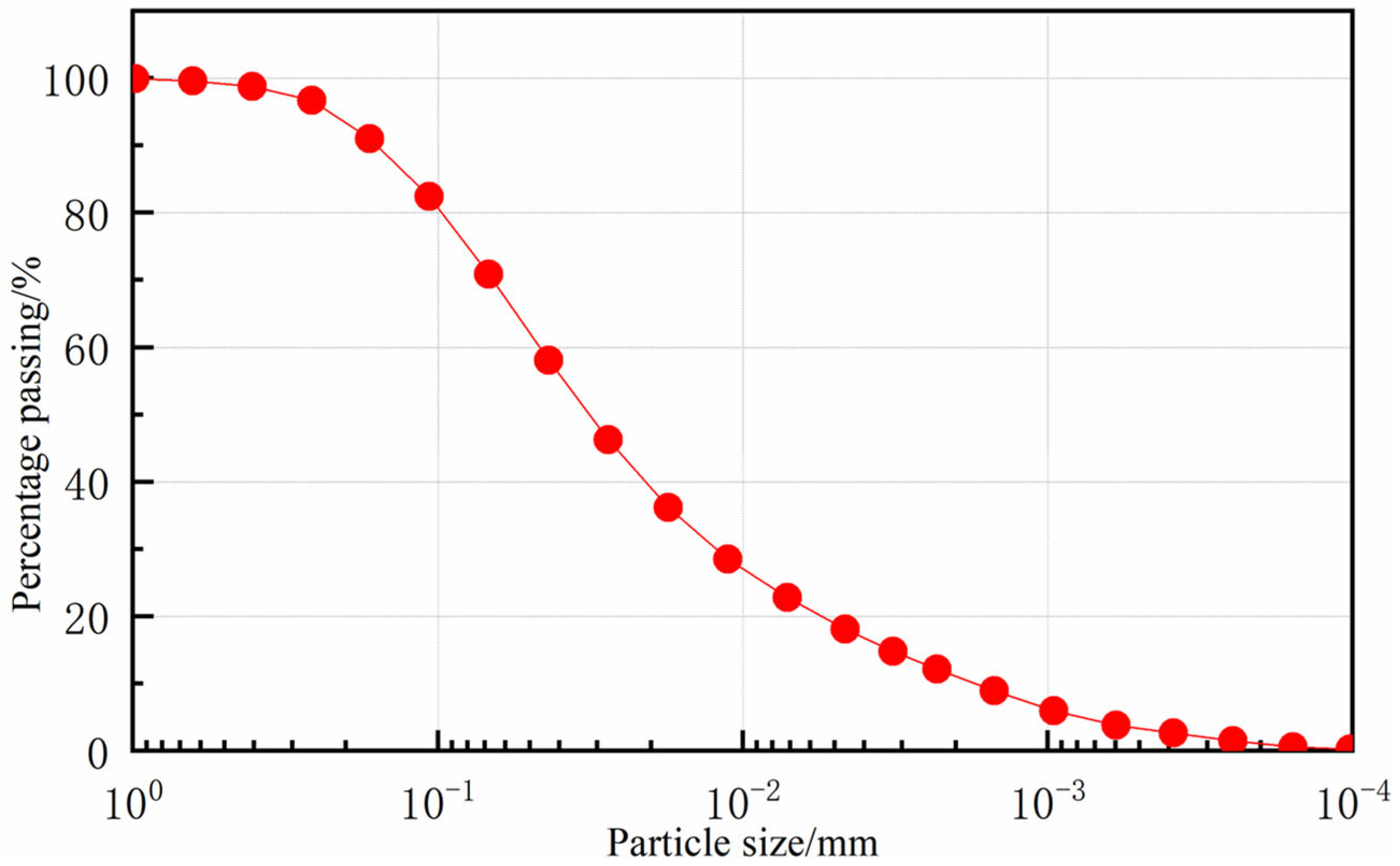
In this study, the soil samples were collected from the Ecological Restoration Base in the South Campus of Hubei University of Technology in Wuhan, Hubei Province (originally excavated from the construction foundation pit of Nanhu Chenggong Garden). Prior to the sheet pile bank protection model test, the soil was air-dried, crushed, and passed through a 2 mm sieve to remove impurities and ensure uniformity. The soil particle size distribution was determined using a laser particle size analyzer, as shown in Figure 1. Although a 2 mm sieve was used for preparation, the laser particle size analysis confirmed that 100% of the tested clay particles were smaller than 1 mm; consequently, the particle size distribution curve in Figure 1 is presented starting from 1 mm to highlight the characteristics of the fine-grained fractions. Subsequently, tests were conducted to determine the basic physical properties of the soil, with the results summarized in Table 1. According to the particle size distribution and Atterberg limits, the tested soil was mainly composed of clay particles and can be classified as clay soil.
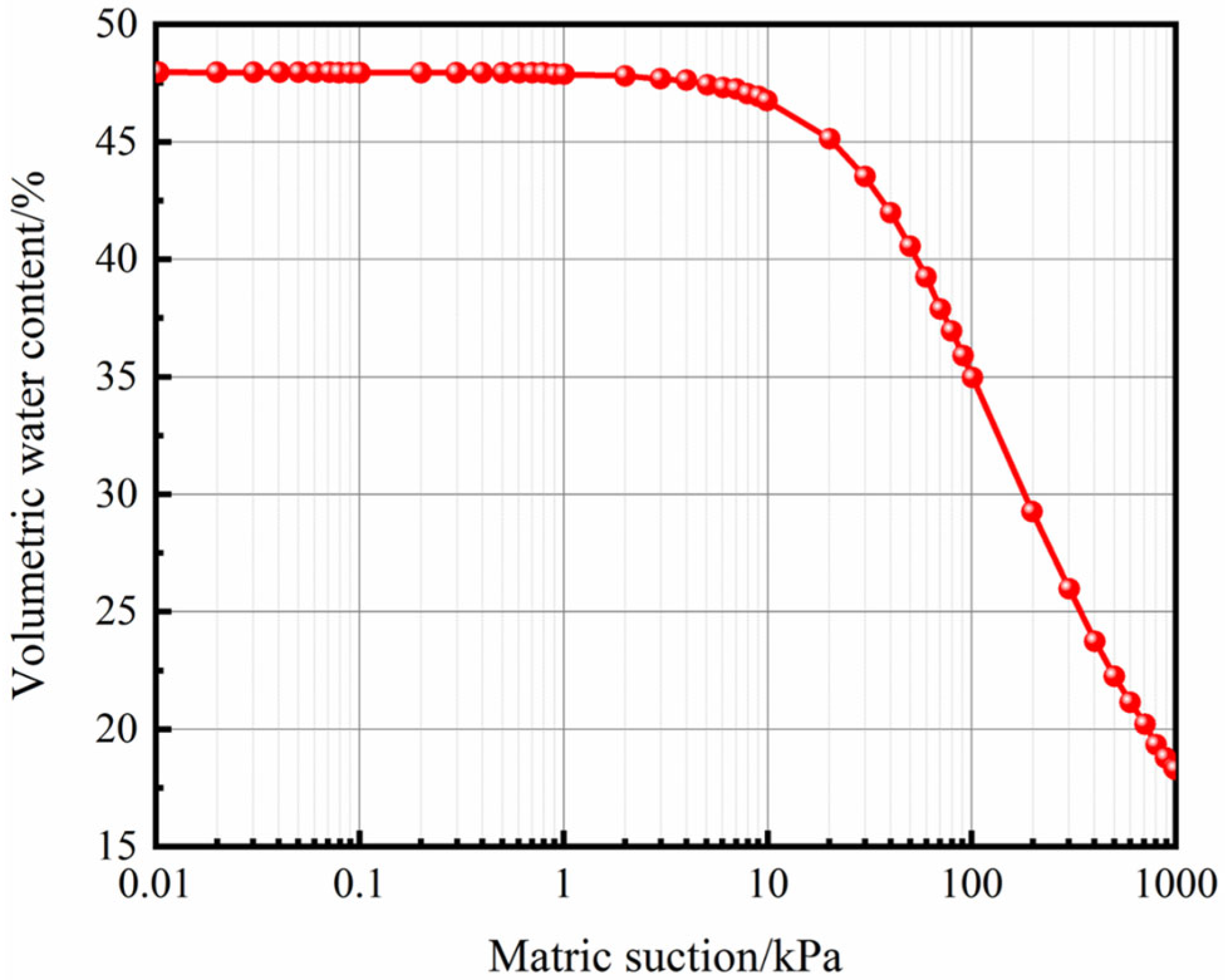
To facilitate the seepage field analysis in the subsequent numerical simulations, the hydraulic characteristics of the test soil were systematically evaluated first. A GCTS Fredlund pressure plate extractor was employed to measure the Soil–Water Characteristic Curve (SWCC). Based on the discrete data points obtained from the test, the Van Genuchten model was utilized for fitting to derive a continuous and complete SWCC, as depicted in Figure 2. The expression for the Van Genuchten model is as follows:
θ = θ r + θ s θ r 1 + a ψ n m ,
where θ represents the volumetric water content of the soil, θ r is the residual water content, θ s is the saturated water content, a , n , and m are fitting parameters, and ψ denotes the matric suction.
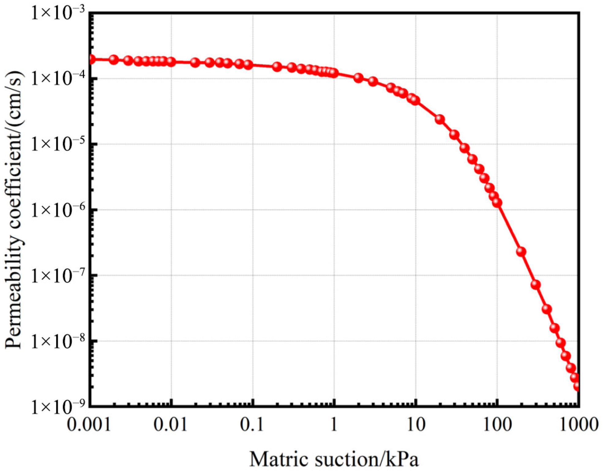
The saturated hydraulic conductivity of the soil was determined using a double-cell variable-head automatic permeameter, which primarily consists of an air pressure source, a water supply device, a seepage pressure gauge, a three-way switch, a water head tube, and a differential pressure sensor. By combining the saturated hydraulic conductivity with the SWCC, the unsaturated hydraulic conductivity was obtained, as shown in Figure 3.

2.2. Bank Slope Test Apparatus and Model Setup

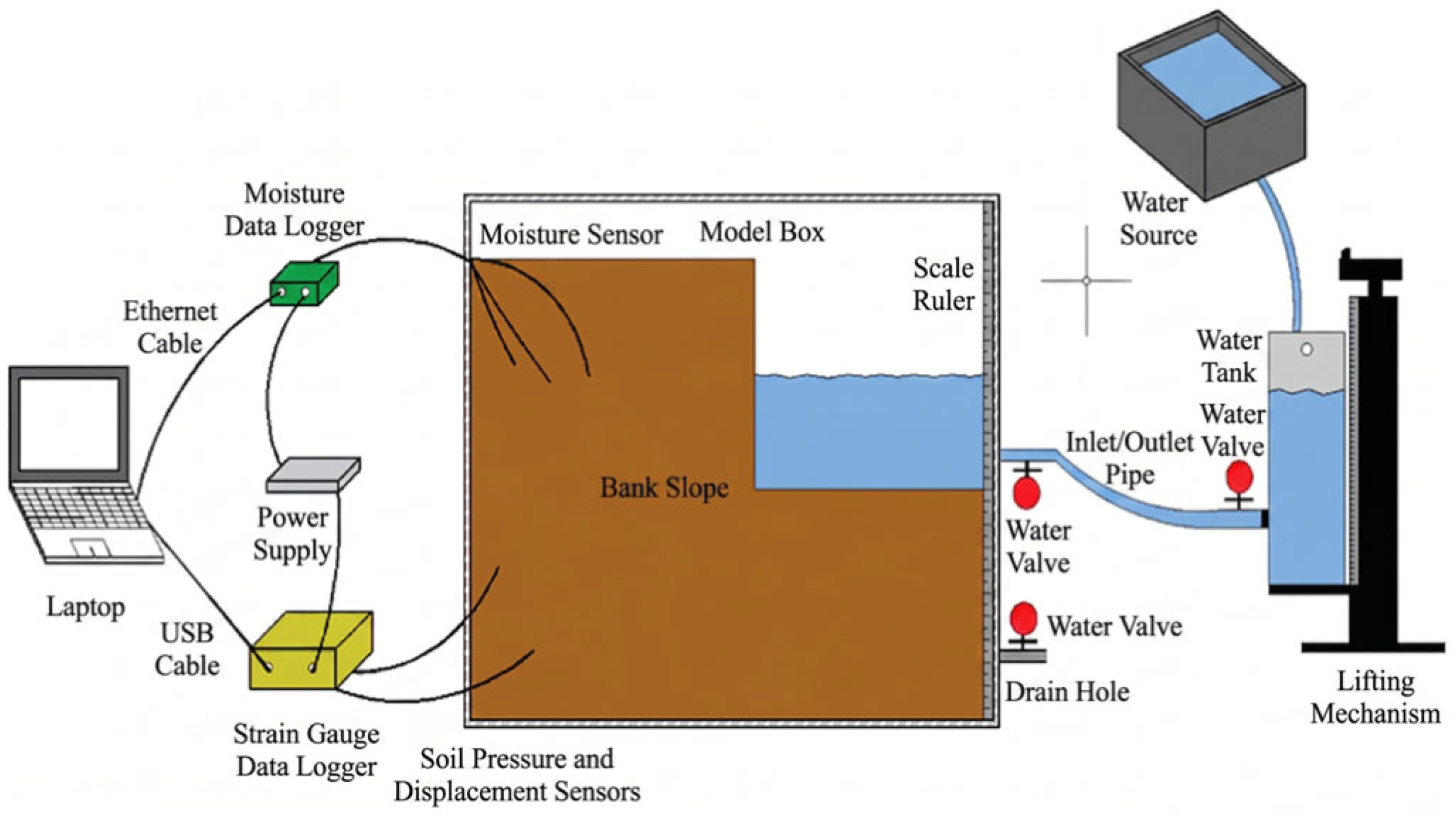
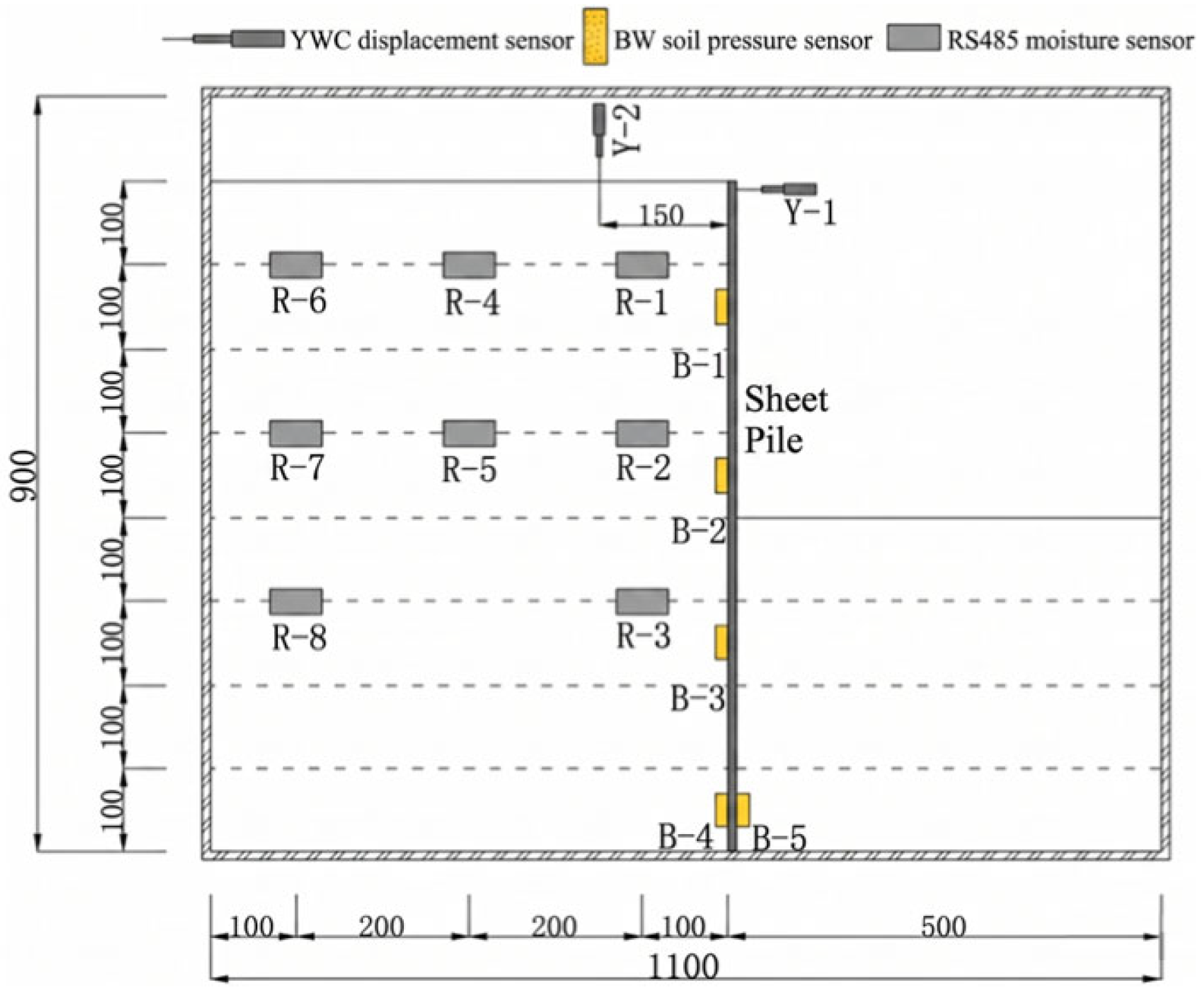
The indoor physical model testing system mainly comprises a model box, a water level control system, a sensor monitoring system, and a bank slope simulation device. The water level control system is a custom-designed apparatus consisting of a lifting platform, a water tank, inlet and outlet pipes, and valves. The water tank is replenished through an external pipeline, and a drainage valve is installed at the top to maintain a constant water level. By adjusting the height of the lifting platform, the gravitational potential energy difference is utilized to drive the water flow, thereby achieving precise control and dynamic simulation of the water level. The model box is constructed from 10 mm thick acrylic glass and reinforced with square steel tubes, allowing for direct visual observation of the deformation and failure of the bank slope soil during the test. All sensors were strictly calibrated prior to the test; their final layout is shown in Figure 4, and the measuring point locations are detailed in Figure 5.
The experimental monitoring system primarily comprises volumetric water content (VWC), earth pressure, and displacement sensors. VWC was monitored using RS485-type temperature and moisture transmitters manufactured by Shandong Jianda Renke (Jinan, China). Eight moisture sensors were connected in parallel to a network data logger via 4-pin interfaces, transferring data to a computer-based monitoring software through an Ethernet cable. Furthermore, earth pressure and displacement were recorded using five BW miniature earth pressure cells and three YWC strain-type displacement sensors, respectively, all supplied by Liyang Jincheng Test Instrument Factory. These sensors were connected to the No. 4–8 and No. 1–3 RS485 ports of a YBY-801 dynamic and static resistance strain indicator via 4-pin interfaces. The indicator was subsequently linked to a computer via a USB cable, facilitating the automated monitoring and data logging of both parameters through dedicated software. The technical parameters of the sensors are summarized in Table 2.
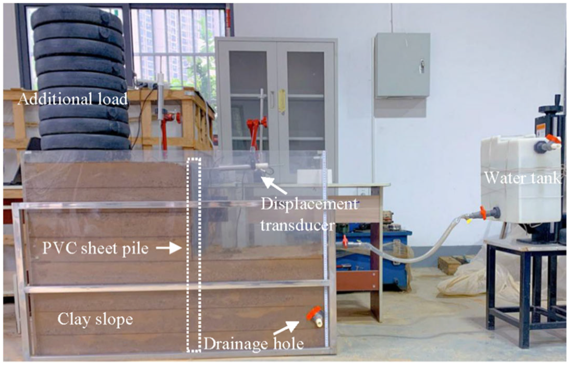
The physical model was partitioned into two rectangular zones for lift-by-lift construction with a layer thickness of 10 cm. Zone I (60 × 40 × 80 cm) comprised 8 layers, with 45 kg of soil prepared per layer to account for material loss, while Zone II (50 × 40 × 40 cm) consisted of 4 layers with 40 kg of soil per layer. During the filling process, the initial volumetric water content and dry density were rigorously controlled at the optimum value of 18% and 1.5 g/cm3, respectively. The specific construction procedure was as follows: the raw soil was crushed and sieved, then mixed with water to reached the target moisture content. The mixture was sealed for 24 h to ensure moisture equilibration, followed by multiple verification tests of the water content. Subsequently, pre-calculated masses of soil were poured into the model box in batches according to elevation marks pre-drawn on the container walls. Each layer was compacted using a tamper following the “low-amplitude and high-frequency” principle until the design elevation was reached. During compaction, moisture and earth pressure sensors were embedded synchronously and integrated with the monitoring system for continuous data acquisition until the bank slope was completed. To ensure significant and observable deformation of the sheet piles, a 200 kg surcharge was applied at the slope crest. Based on the vertical stress equivalence principle widely adopted in physical model tests [24], this surcharge provides an equivalent vertical pressure that accurately simulates the overburden weight of an additional 60 cm-thick overlying soil layer. The final physical model of the bank slope is illustrated in Figure 6.
To ensure the scientific validity and field transferability of the indoor test, the experimental setup was designed with careful consideration of similitude criteria. Geometrically, the 0.8 m sheet pile in the model corresponds to a 12 m prototype support evaluated in subsequent field-scale analyses, representing an implicit geometric scaling factor of n = 15. Mechanically, due to the low-stress limitations of 1-g physical modeling, the aforementioned 200 kg surcharge was essential to compensate for insufficient self-weight, providing an equivalent vertical pressure of an additional 60 cm soil layer and ensuring realistic shear strength mobilization. Hydraulically, the water level fluctuation rates were designed to reliably reproduce the characteristic “transient pore pressure lag” mechanism commonly observed in field applications. Regarding transferability, the physical model serves primarily to elucidate fundamental deformation mechanisms and to validate the numerical modeling framework The quantitative evaluation of field conditions is then reliably achieved by applying this validated numerical approach to full-scale prototype dimensions, effectively bridging laboratory observations with actual engineering practices.

2.3. Design of PVC Sheet Piles

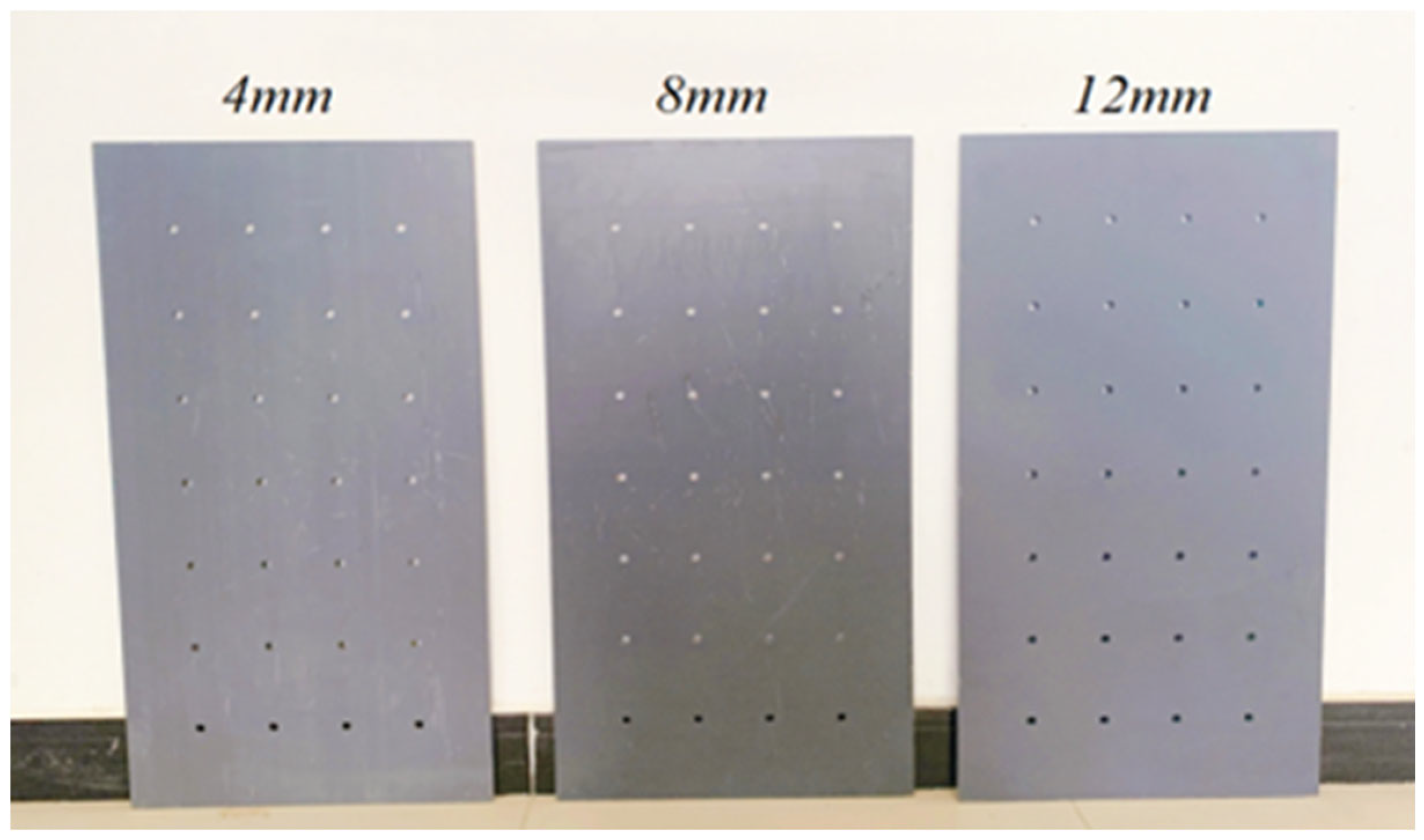
The physical model test in this study aims to explore the dynamic mechanical and deformation behaviors of supporting structures with different stiffnesses during water level fluctuations. Because the dimensions of the physical model are significantly smaller than the actual engineering scales, the material stiffness of the supporting structure must not be excessive, which would otherwise obscure the experimental phenomena and impede result analysis. Therefore, Polyvinyl Chloride (PVC)—the primary component of plastic steel—was selected as the supporting material. Rigid PVC is typically used in independent structures and is widely applied in the manufacture of building formworks. Recently, a few scholars have attempted to utilize it in riverbank and levee protection and anti-seepage projects, such as sheet piles and fences, and have conducted related experimental studies [20,25]. Based on the geometric dimensions of the bank slope model, this study designed rectangular cross-section sheet piles with a length of 80 cm and a width of 40 cm to simulate the protective effect of a single, complete sheet pile unit on the bank slope in actual engineering. To investigate the effects of different stiffness conditions, the thickness of the sheet piles was set to 4 mm, 8 mm, and 12 mm, respectively. The design schematic is illustrated in Figure 7. To ensure the stability of the mechanical properties of the PVC material, all indoor tests were conducted in a temperature-controlled environment at a constant temperature of 22 ± 2 °C.
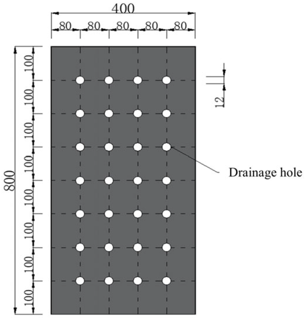
Drainage holes were arranged in rows along the height of the sheet pile, with a spacing of no more than 3.0 m in actual applications. According to the recommended hole diameter of 50–80 mm in the Construction Specifications for Plastic-Steel Sheet Pile Retaining Walls in Water Conservancy Projects, and considering the scale effect of the model, the drainage holes in this study were designed with a diameter of 12 mm, a vertical spacing of 10 cm, and a horizontal spacing of 8 cm. Due to the creep effect of PVC sheet piles, their displacement often reaches the limit state earlier than the internal forces. When utilized as a long-term structure with a designed service life of 30 years, an elastic modulus reduction factor of 0.65 is applied. The relevant design parameters are listed in Table 3, and the sheet pile layout is shown in Figure 8. The drainage hole diameter was standardized at 12 mm across all pile thicknesses to isolate the influence of structural stiffness by ensuring consistent hydraulic boundary conditions. Furthermore, the engineering-grade PVC material used in this study is formulated with impact modifiers to maintain structural quality under diverse environmental conditions, including potential low-temperature exposure in field applications.

2.4. Experimental Condition

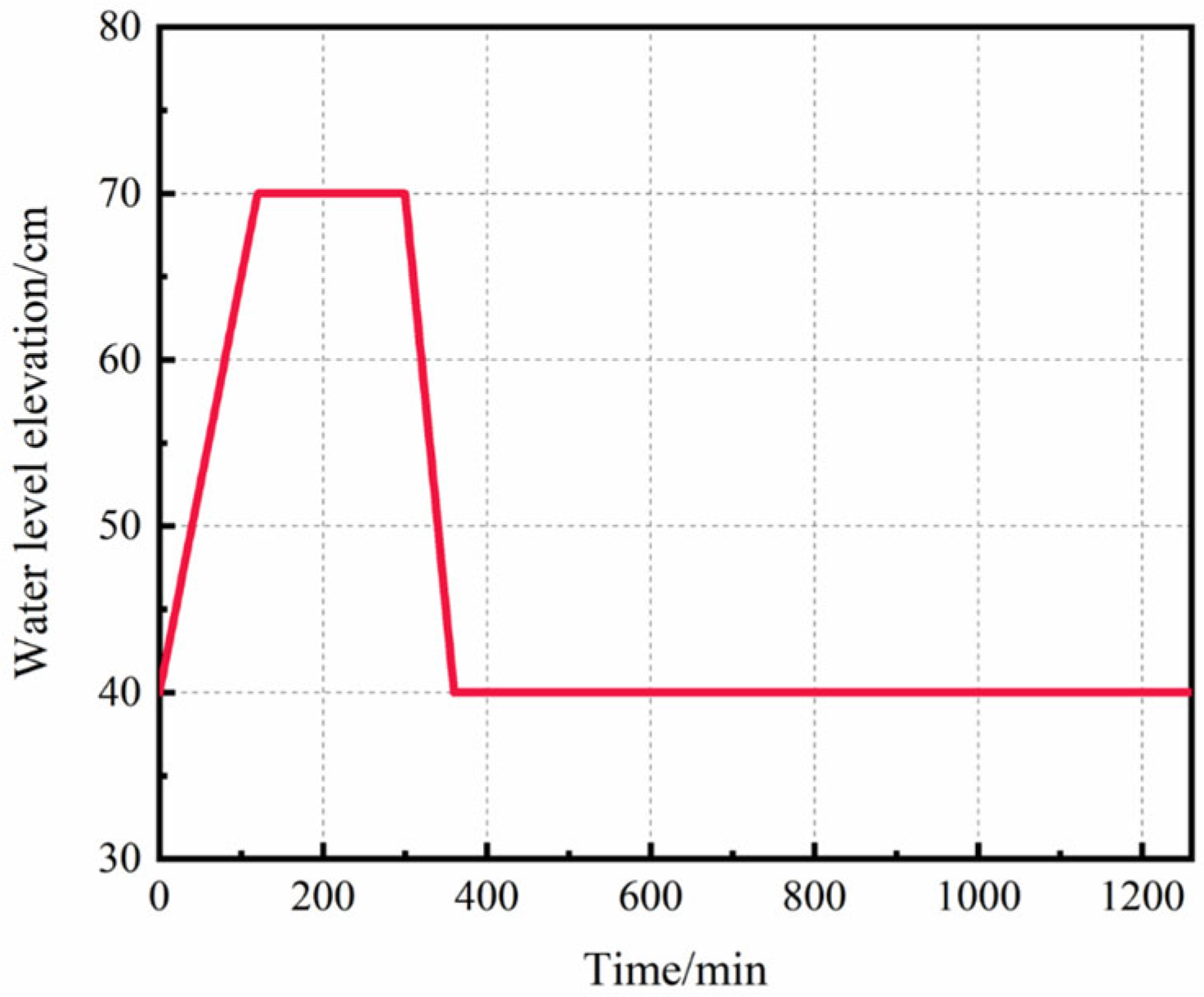
In this study, a water level fluctuation system was utilized to simultaneously control the water elevation and its duration, thereby simulating the field conditions of water level rise, stabilization, and drawdown in bank slopes. Previous studies have demonstrated that bank slope failures predominantly occur during the drawdown phase, and rapid drawdown rates are particularly prone to triggering instability [26,27]. Accordingly, the experimental rates for water level rise and drawdown were set to 0.25 cm/min and 0.5 cm/min, respectively. The variation in the water level over time is illustrated in Figure 9. The primary variable in the physical model tests was the sheet pile stiffness, which was controlled by varying the thickness of the sheet piles. A total of four test cases were established: an unreinforced slope (control group), and slopes reinforced with 4 mm, 8 mm, and 12 mm thick sheet piles. The detailed experimental programs are summarized in Table 4.

3. Experimental Results and Analysis

3.1. Spatiotemporal Variation in Bank Slope Moisture

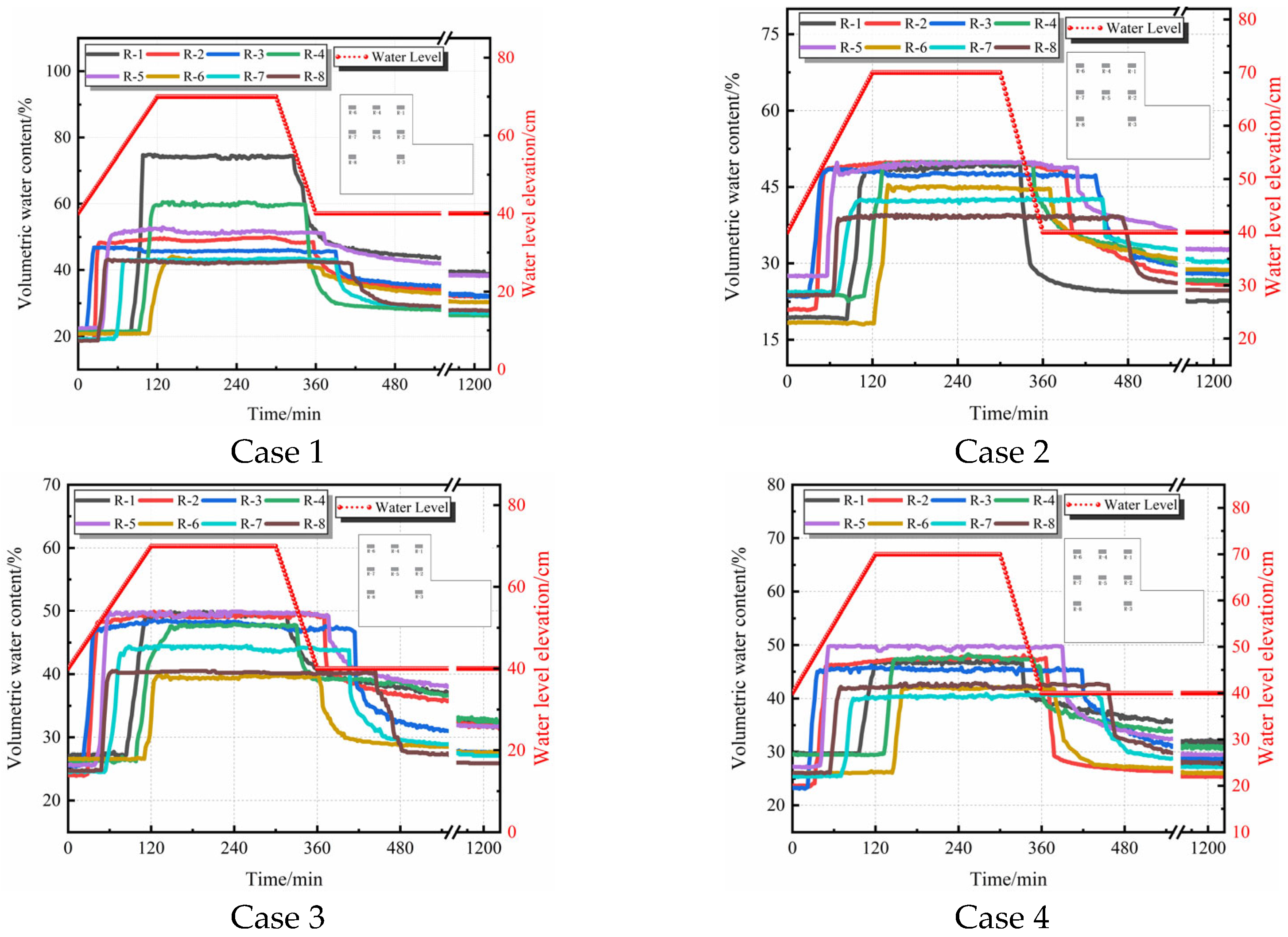
Figure 10 illustrates the variation in the volumetric water content of the bank slope soil over time under the conditions of no sheet pile and sheet pile supports with thicknesses of 4 mm, 8 mm, and 12 mm. Overall, the water content curves are highly consistent with the water level fluctuations: during the water level rising stage, the soil water content increases rapidly and tends to stabilize during the constant water level stage; when the water level drops, the water content decreases accordingly until a new equilibrium state is reached. However, under different support conditions, significant differences exist in the initiation time, growth rate, and decline response of the water content variations.
During the gradual rise in the water level, taking measuring point No. 6 (which exhibited the longest response time) as an example, the water content in the unsupported group began to increase at 108 min, whereas in the 4 mm, 8 mm, and 12 mm sheet pile groups, the initiation was delayed to 112 min, 124 min, and 146 min, respectively. The primary reason is that the sheet piles exerted a direct water-blocking effect, thereby increasing the resistance to inward moisture seepage.
During the gradual drawdown of the water level, conversely, the sheet piles prolonged the time required for internal moisture to drain from the bank slope. Taking the deep measuring point No. 8 as an example, the water content of the unsupported group began to decrease at 416 min. Following the installation of the 4 mm, 8 mm, and 12 mm sheet piles, the decline at measuring point No. 8 lagged to 446 min, 474 min, and 458 min, respectively. This indicates that the sheet piles impeded the outward dissipation of moisture within the slope, resulting in a general delay of 30 to 58 min in the water level drawdown in the middle and deep layers of the slope mass.

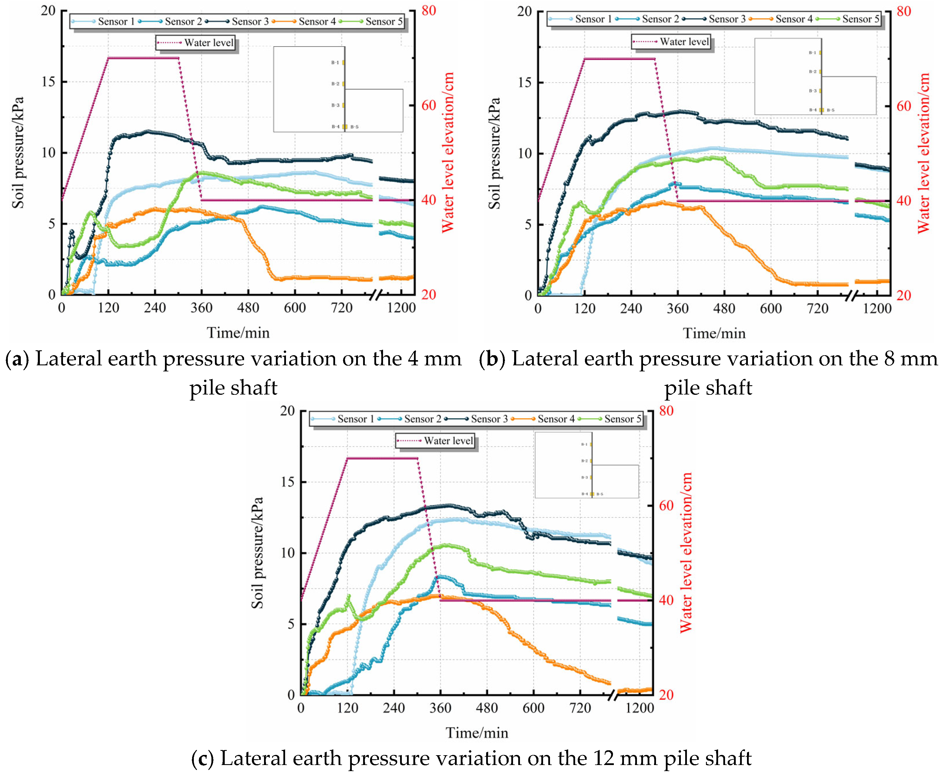
3.2. Variation Law of Lateral Earth Pressure on the Pile Shaft

As shown in Figure 11, during the water level fluctuation cycles, the lateral earth pressure on the pile shaft generally exhibited an evolutionary characteristic of “continuous increase—delayed peak—slow decline.” During the water level rising and maintaining stages, the lateral earth pressure continuously increased. However, during the drawdown stage, because the moisture drainage within the slope was slower than the external water level drop, the lateral earth pressure did not decrease synchronously; instead, it universally lagged, reaching its global peak only after the water level dropped to the initial line (around 360 min). Regarding spatial distribution and stiffness response, the maximum earth pressures were concentrated near the riverbed (measuring point No. 3), and the peak values significantly increased with the greater stiffness of the sheet piles. The maximum values measured for the 4 mm, 8 mm, and 12 mm sheet piles were 11.5 kPa, 12.9 kPa, and 13.3 kPa, respectively. This directly indicates that sheet piles with greater stiffness exert stronger displacement constraints on the soil, thereby passively bearing higher local sliding thrust. Furthermore, the experimental monitoring captured a nonlinear fluctuation of “initial increase—brief decrease—subsequent increase” in the earth pressure in the stressed area (measuring points No. 2, 3, and 5) of the low-stiffness 4 mm sheet pile, a phenomenon essentially absent in the 8 mm and 12 mm sheet piles. This data difference visually confirms the “yielding unloading mechanism” of flexible sheet piles: during the initial loading phase, low-stiffness sheet piles undergo significant elastic yielding deformation, actively releasing the accumulated stress within the soil and creating a macroscopic, temporary depressurization effect. Conversely, medium-to-high stiffness sheet piles, due to their minimal deformation and near-rigid constraint, fail to release stress effectively, causing their earth pressure to remain continuously high.

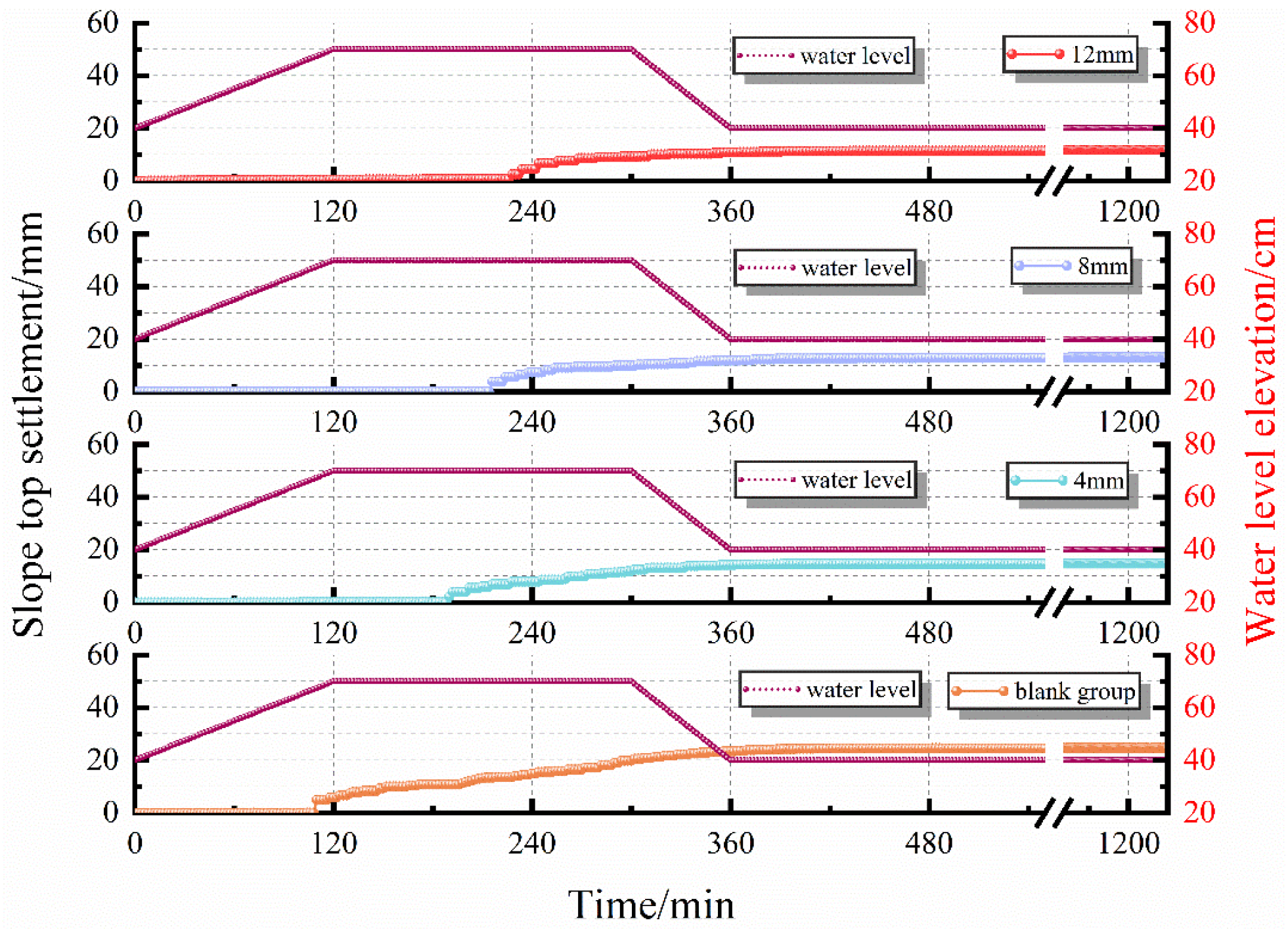
3.3. Variation Law of Bank Slope Top Settlement

Figure 12 illustrates the comparison of the bank slope top settlement under the four sets of experimental conditions. Under the cyclic action of water level fluctuations, the sheet pile stiffness exerted a strong control effect on the initiation time and ultimate displacement of the bank slope settlement. Using a 1 mm settlement as the deformation initiation baseline, the initial settlement of the unsupported group occurred at 110 min during continuous moisture infiltration. However, following the installation of the 4 mm, 8 mm, and 12 mm sheet piles, the settlement initiation times were significantly delayed to 190 min, 216 min, and 228 min, respectively. Regarding the control of ultimate settlement, the maximum settlement at the slope top in the unsupported group reached 24.6 mm. The 4 mm, 8 mm, and 12 mm sheet pile groups effectively reduced this to 14.7 mm, 13.0 mm, and 11.8 mm, respectively, with the 12 mm sheet pile achieving a 52.0% reduction in ultimate settlement. Additionally, when the external water level dropped to its lowest point at 360 min, the slope settlement in all groups did not cease, indicating a significant lag in settlement deformation relative to water level changes. The primary reason for these trends is that the greater the stiffness of the sheet pile, the stronger the reverse structural constraint force it provides, forcing the soil mass to accumulate moisture over a longer period to overcome the resistance and produce macroscopic deformation.

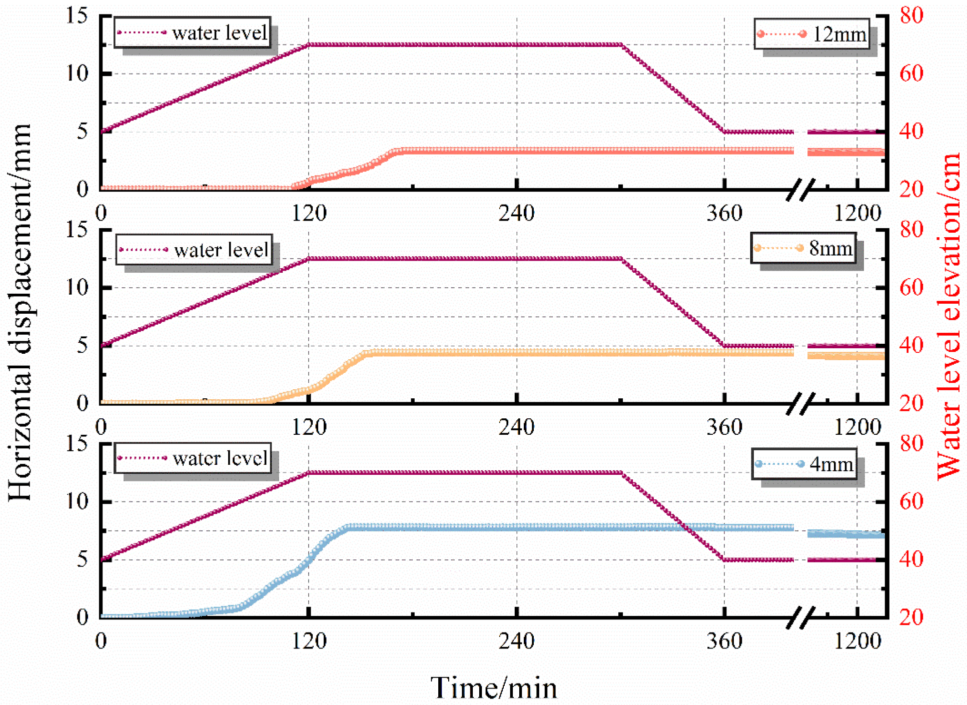
3.4. Variation Law of Horizontal Displacement at the Pile Top

Figure 13 displays the dynamic evolution process of the horizontal displacement at the top of the sheet piles with different stiffnesses. Overall, the horizontal displacement at the pile top presented a trend of “stability—sudden increase—rebound convergence.” As the sheet pile stiffness increased, the displacement initiation time (based on reaching 0.6 mm) was gradually prolonged from 66 min for the 4 mm sheet pile to 104 min and 120 min for the 8 mm and 12 mm sheet piles, respectively. Concurrently, the maximum horizontal displacement was sequentially reduced from 7.8 mm for the 4 mm sheet pile to 4.45 mm and 3.4 mm for the 8 mm and 12 mm sheet piles, respectively. During the moisture dissipation stage after the water level dropped to its lowest point, all three groups of PVC sheet piles exhibited varying degrees of rebound reduction trends. The rebound amounts for the 4 mm, 8 mm, and 12 mm sheet piles were 0.70 mm, 0.37 mm, and 0.17 mm, respectively. This phenomenon indicates that flexible PVC materials are prone to flexural elastic deformation under load, and the lower the stiffness of the sheet pile, the higher the proportion of its elastic deformation. In the later stages of the experiment, as the moisture content in the slope decreased, the effective stress of the soil recovered, and the sliding force diminished, the elastic recovery toward the initial state was more pronounced in the low-stiffness sheet pile. Referring to the allowable mudline horizontal displacement value of 15 mm stipulated in the Technical Code for Plastic-Steel Sheet Pile Retaining Walls of Water Conservancy Projects, none of the three sheet pile groups reached the failure state.

3.5. Numerical Analysis of Bank Slope Seepage Field and Mechanical Deformation Characteristics of Sheet Piles

A three-dimensional numerical model was established based on the dimensions of the physical model and the sensor locations. To verify the accuracy and reliability of the numerical model, the simulated volumetric water content (VWC) of the unsupported bank slope under water level fluctuations was compared with the measured experimental data.
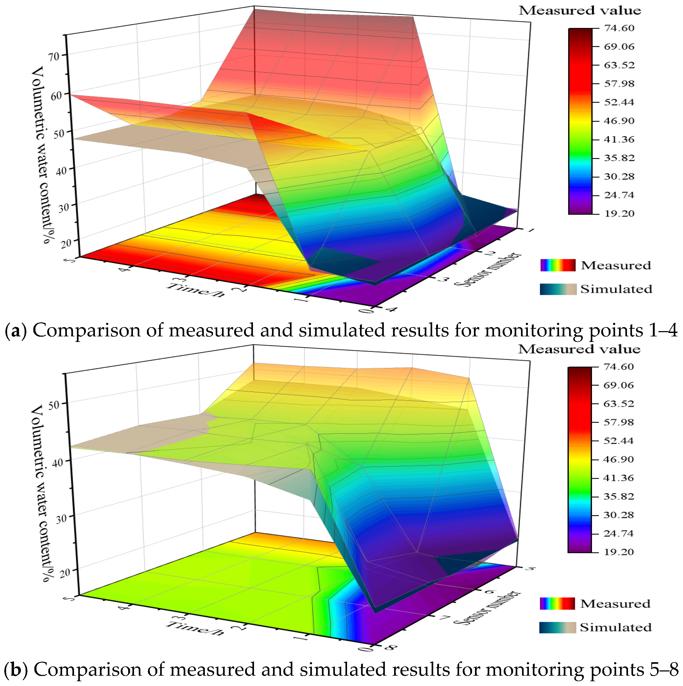
Figure 14 illustrates the comparison between the measured and simulated VWC at monitoring points 1 to 8 for the unsupported group. The overall trends of the two data surfaces are highly consistent. However, notable discrepancies were observed at monitoring points 1 and 4 during the 3–5 h period, with maximum errors reaching 41% and 23%, respectively. This is primarily attributed to a localized landslide at the slope crest during the physical test, which reduced the soil cover over these upper sensors and exposed them to excessive moisture—a physical deformation process that was not accounted for in the numerical simulation. Excluding these specific points, the variations in data at the remaining monitoring points exhibited a high degree of similarity, with errors tightly maintained within 10%. Considering that moisture infiltration in actual bank slopes is also influenced by environmental factors difficult to fully incorporate into the numerical model, such as ambient temperature, humidity, and evaporation, the current discrepancies are deemed entirely acceptable. These results demonstrate that the numerical model is fundamentally reliable and can serve as a robust basis for subsequent extended studies.
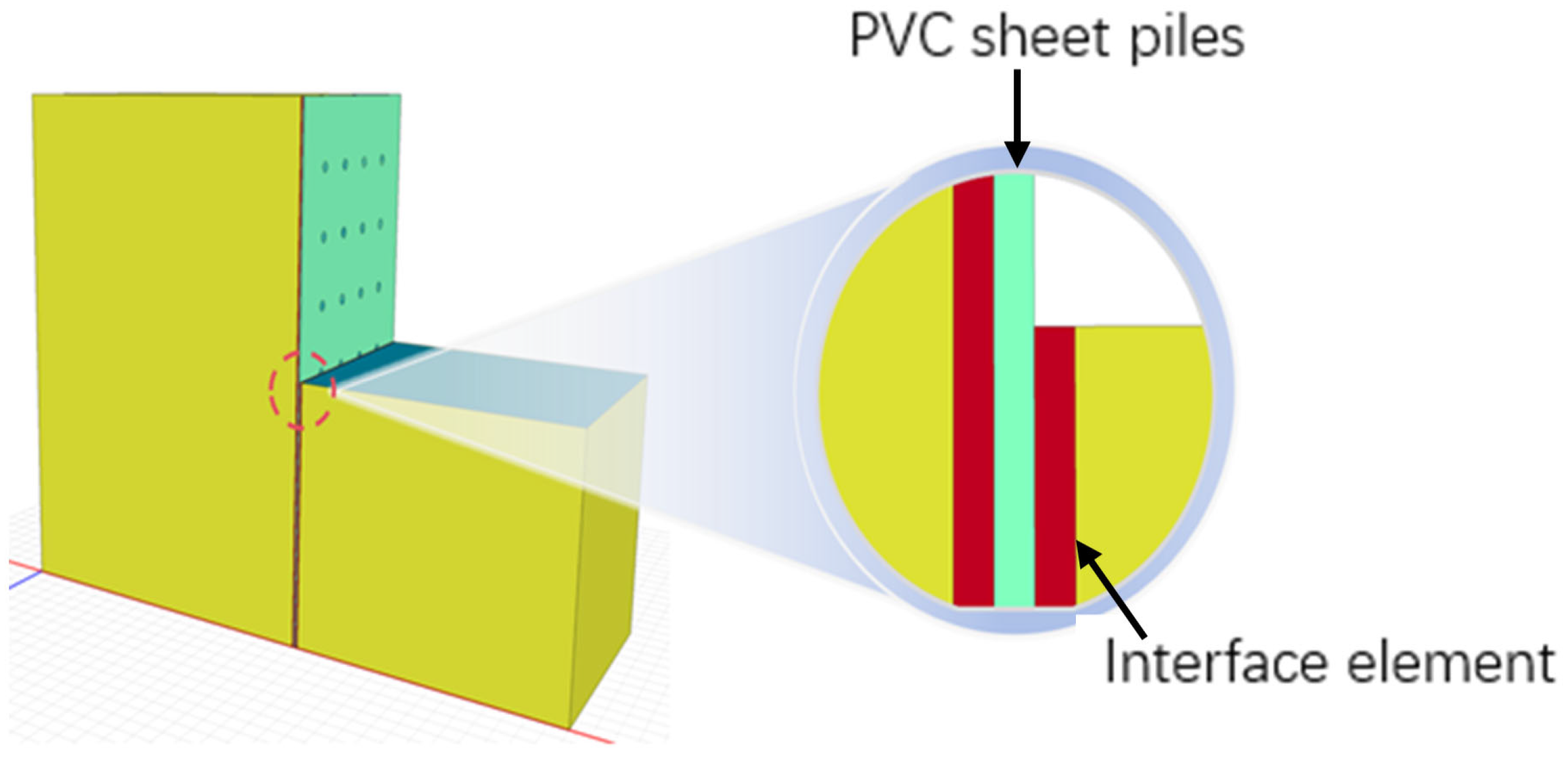
In this study, the Geo-Studio [2022] simulation software was selected to conduct a stability analysis of the bank slope supported by perforated sheet piles under the coupling of transient seepage and stress–strain using a three-dimensional model. The bank slope soil utilized a saturated/unsaturated model, with its hydrological parameters defined by previous VG model fitting and permeability tests. The initial moisture content (18%) was assigned via the corresponding negative pore water pressure. The mechanical properties of the soil all adhered to the Mohr-Coulomb elastoplastic constitutive criterion. The PVC sheet pile was modeled using linear elastic solid elements, with an aquiclude applied to the unperforated areas, while the drainage holes were equivalently modeled as cylindrical elements with high hydraulic conductivity (1 m/s) to simulate local unidirectional seepage. The bottom of the model was fixed and impermeable, and lateral constraints were applied to both sides to eliminate boundary effects. The mechanical parameters of the model are listed in Table 5, and the 3D model diagram is shown in Figure 15.

3.5.1. Dynamic Influence Law of Water Level Fluctuation Rate on the Pore Water Pressure Field of the Bank Slope

This section conducted a multi-scenario parametric study. Given that the numerical model was proportionally scaled up, the water level fluctuation condition parameters were matched and adjusted accordingly to ensure the simulation process could fully represent the response laws of the physical model under complex hydrological conditions (detailed in Table 6). By comparatively analyzing the coupling characteristics of the internal hydraulic response and structural stress–strain of the bank slope under different fluctuation rates, this study aims to reveal the key influence mechanisms of bank slope instability induced by water level fluctuations.
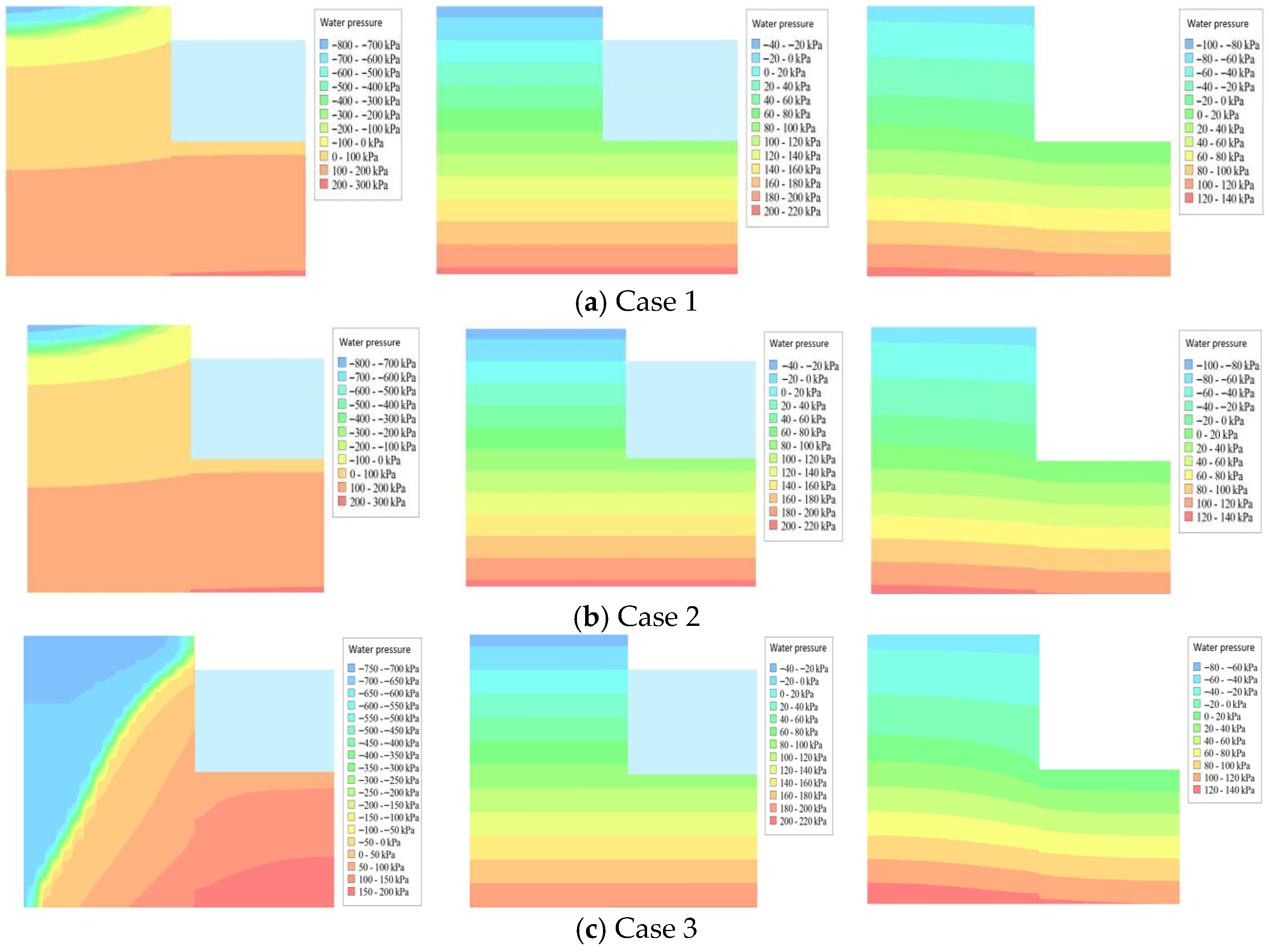
Figure 16 reveals the dynamic influence law of the water level fluctuation rate on the evolution of the bank slope’s pore water pressure field. The study found that the lag effect of the pore pressure response intensified significantly with the accelerated rate of water level change, and it exhibited diametrically opposite control effects on slope stability at different stages of the hydrological cycle. Specifically, during the water level rising stage, rapid elevation led to a severe lag in the internal pore pressure response and steep contour lines. In the short term, this lag effect effectively restricted the inward cumulative diffusion of pore pressure, relatively maintaining a higher effective stress in the soil, which promoted the initial stability of the bank slope. After entering the maximum water level maintaining stage (90 d), with continuous infiltration seepage, the early dynamic lag effect gradually dissipated, and the overall slope mass tended toward saturation. Ultimately, the pore pressure field distribution under various rate conditions trended toward equilibrium and high consistency. However, during the water level drawdown stage, the dissipation of internal pore pressure severely lagged behind the sudden drop in the external water level. More critically, the seepage-blocking effect of the sheet pile itself further deteriorated the drainage conditions of the slope. The sudden change in the soil-water coupling boundary triggered an intense excess pore water pressure within the slope directed toward the water-facing side. The overall law indicates that a faster water level drawdown rate not only results in stronger seepage hysteresis but also induces a higher amplitude of excess pore water pressure. This abnormal pore pressure drastically weakened the effective stress of the soil, significantly increasing the instability risk of outward sliding of the bank slope.

3.5.2. Influence Law of Water Level Fluctuation Rate on the Mechanical Deformation Characteristics of Sheet Piles

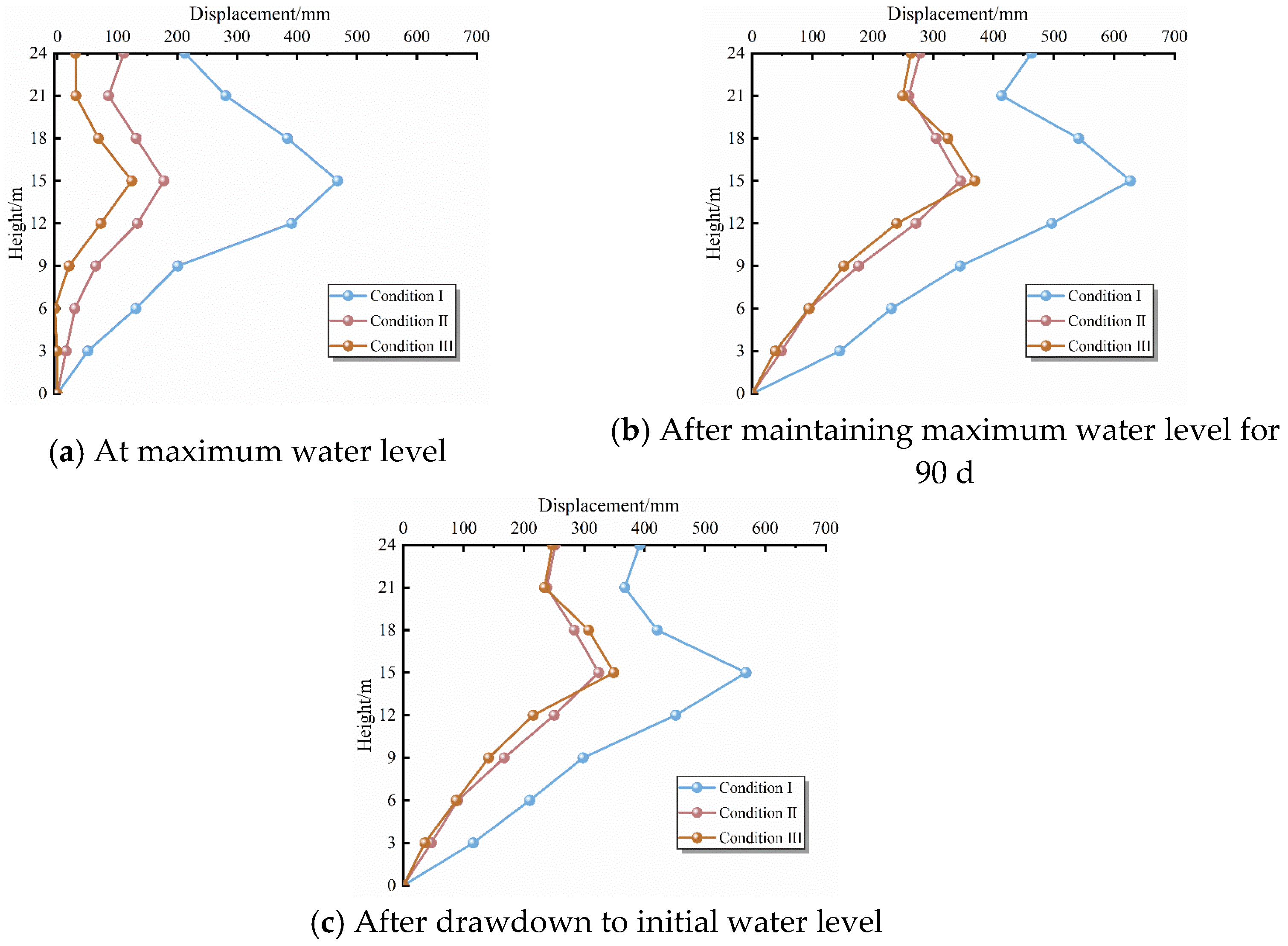
Figure 17 reveals the dynamic driving mechanism of the water level fluctuation rate on the evolution of the horizontal displacement of the PVC sheet pile. Overall, the pile displacement exhibited a “parabolic” distribution along the depth, with the maximum displacement consistently occurring at 15 m (which was taken as the control point for structural failure). Research indicates that the water level fluctuation rate exerted diametrically opposite control effects on pile deformation at different stages: During the water level rising stage, a slower rising rate prolonged the time for moisture infiltration and soil softening. This caused the downward sliding force from the inside of the slope to the outside to far exceed the constraint of the external hydrodynamic pressure, thereby inducing greater positive displacement of the pile. During the maximum water level maintaining stage (90 d), continuous seepage erosion persistently strengthened the downward sliding force, leading to a secondary accumulation of pile displacement under all rate conditions. During the water level drawdown stage, although the dissipation of soil moisture and the sheet pile’s own elasticity prompted an overall reduction in displacement (rebound), the unloading of external hydrodynamic pressure coupled with the superposition of outward excess pore water pressure within the slope significantly weakened the elastic recovery amplitude of the sheet pile. The results indicate that a faster drawdown rate results in a smaller retraction amplitude of the pile displacement.
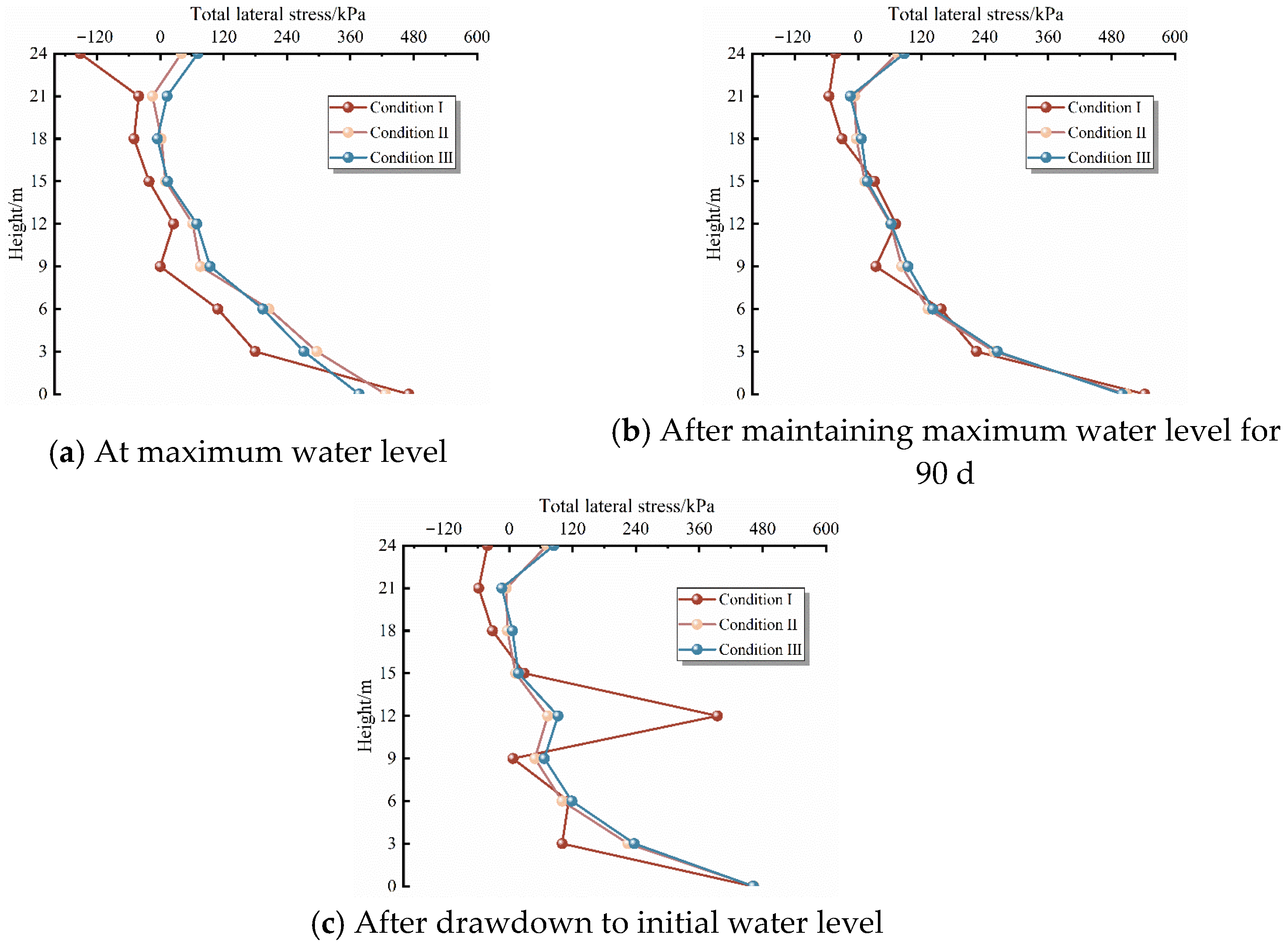
Figure 18 reveals the evolution law of the total horizontal stress on the back-water side of the pile shaft under different water level fluctuation rates. The total horizontal stress of the pile presented a “C”-shaped distribution with increasing buried depth. This stress redistribution is beneficial for reducing the mid-span stress and thereby lowering the bending moment; therefore, the location of maximum horizontal displacement (measuring point at 15 m height) was selected as the representative point for analysis. During the water level rising stage, when the rising rate was relatively fast, the soil was less prone to deform and expand, and the hydrodynamic pressure generated by the water level on the right side increased, resulting in an increase in the stress borne by the pile. During the maximum water level maintaining stage (90 d), moisture continued to infiltrate the bank slope, and the pore water pressure within the slope and the downward sliding force directed toward the water-facing side gradually increased, leading to an increase in the total horizontal stress. During the water level drawdown stage, the unloading of external hydrodynamic pressure caused a decrease in the total horizontal stress of the pile. However, the delayed variation in the groundwater level within the slope generated excess pore water pressure directed from the inside to the outside of the slope. This excess pore water pressure acted to increase the total horizontal stress, and this effect intensified with the accelerated rate of water level drawdown, resulting in a diminished magnitude of decrease in the total horizontal stress compared to the previous stage.

3.6. Numerical Analysis of Overall Stability of Sheet Pile Bank Protection

3.6.1. Effect of Water Level Fluctuation Rate

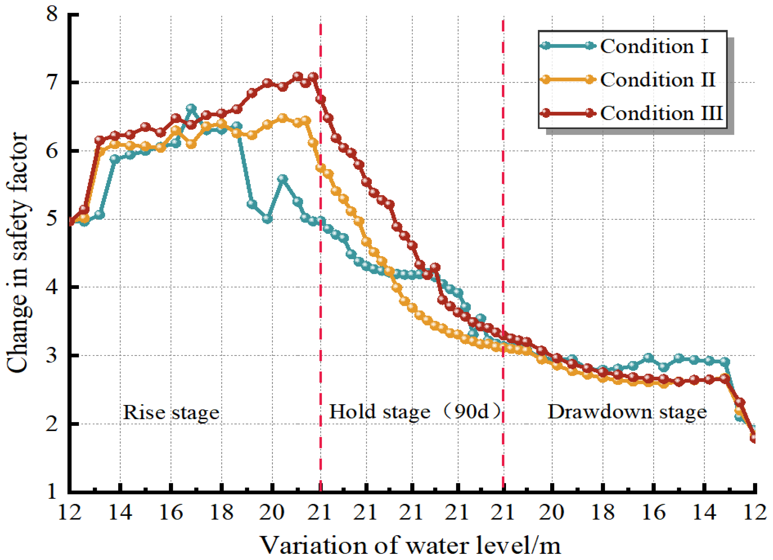
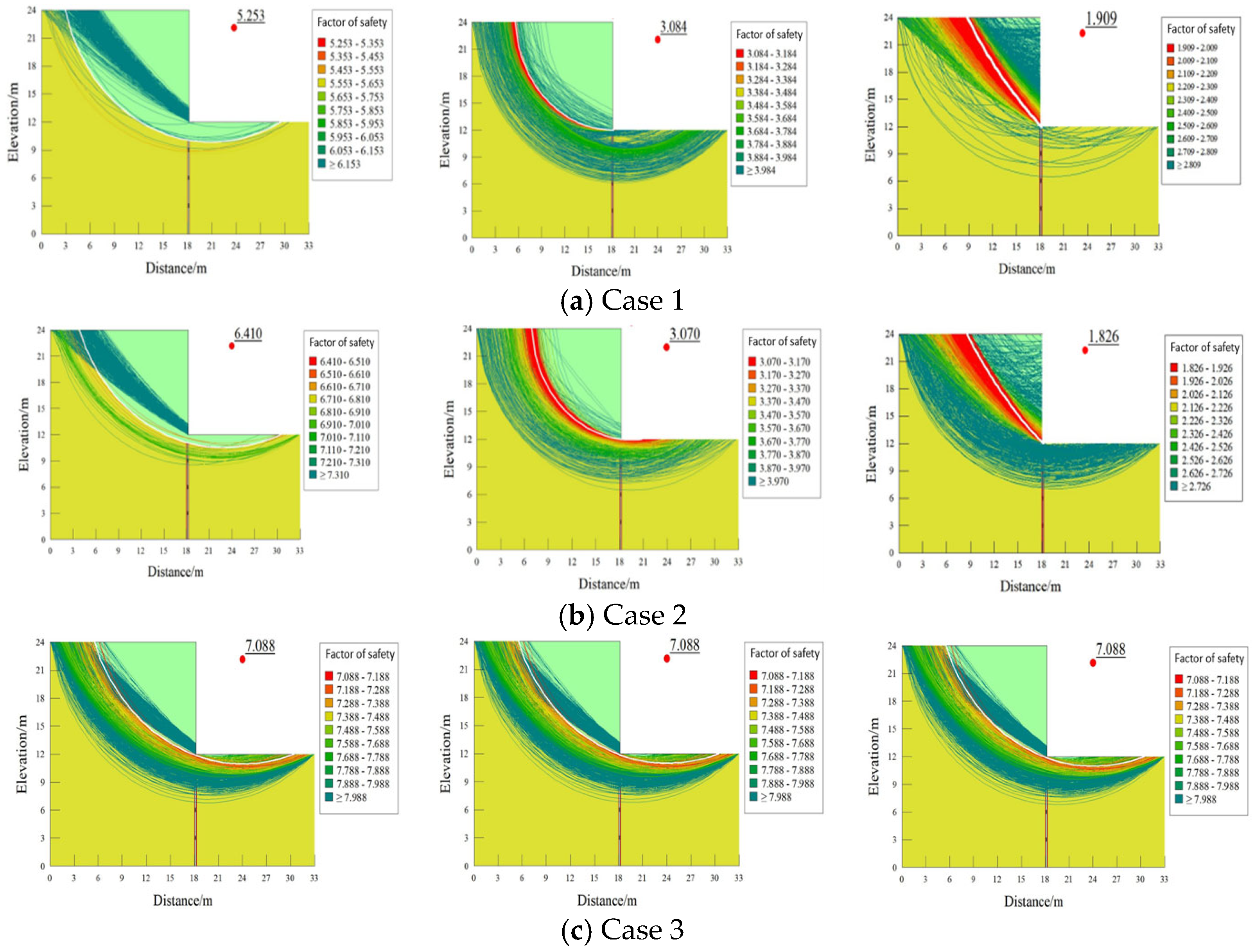
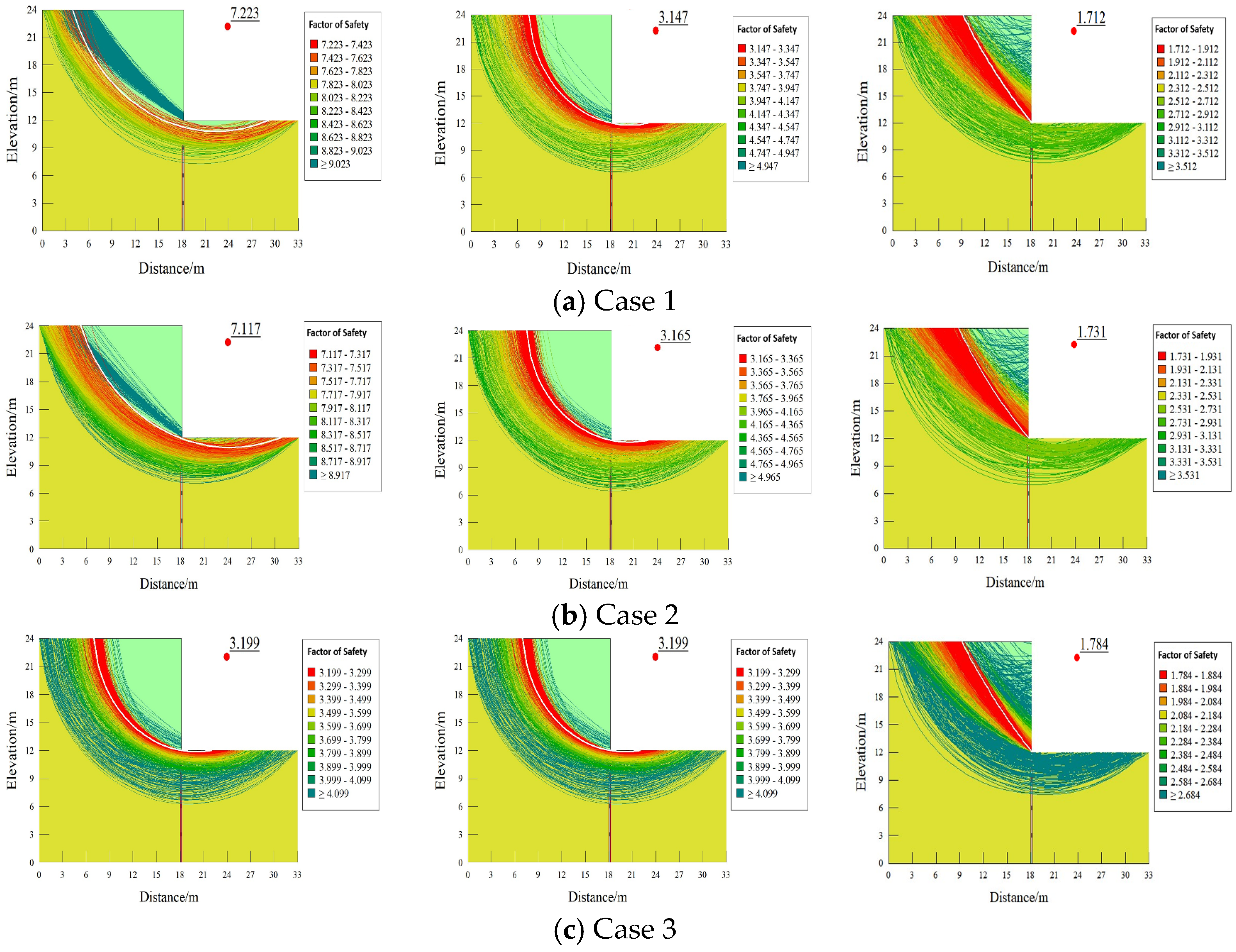
Combining Figure 19 and Figure 20, the dynamic variation laws of the bank slope safety factor and the critical slip surface under different water level fluctuation rates were analyzed. During the water level rising stage, the hydrodynamic pressure generated by the water level, which is directed toward the bank side, exerts a restraining effect on the sliding of the slope. Additionally, the effective unit weight of the soil decreases due to the influence of buoyancy, leading to an improvement in bank slope stability under all operating conditions. As the water level rising rate accelerates, the increment in the safety factor exhibits an increasing trend. The primary reasons are the augmented hydrodynamic pressure and the shorter duration required for a faster rising rate. This makes the lag of the groundwater level within the slope relative to the external water level more pronounced, thereby reducing the degree of moisture erosion experienced by the bank slope. During the water level maintaining stage, moisture infiltrates the bank slope and deteriorates the physical properties of the soil. The differences caused by the lag phenomenon in the previous stage gradually recover, resulting in a continuous decrease in slope stability and a narrowing of the gaps between different conditions. During the water level drawdown stage, because the variation in the groundwater level within the slope lags behind the external water level drop, an excess pore water pressure directed from the inside to the outside of the slope is generated. This causes the slope stability to continue decreasing under all conditions. A faster drawdown rate results in a more obvious lag effect, stronger excess pore water pressure, and a decreasing trend in the safety factor. Therefore, during the water level rising stage, a faster rate significantly enhances bank slope stability, which is beneficial; conversely, during the water level drawdown stage, a faster rate more severely weakens bank slope stability, which is detrimental.

3.6.2. Effect of Sheet Pile Stiffness

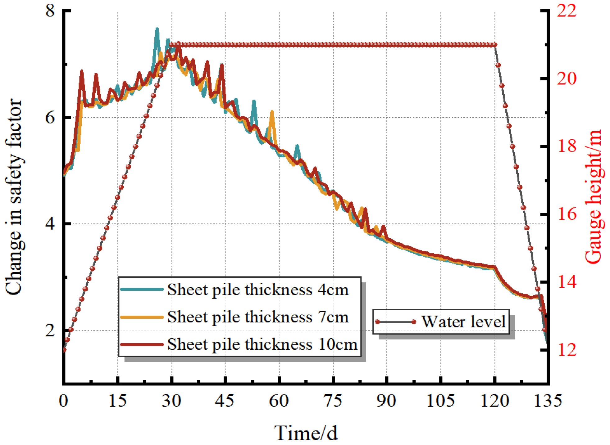
To investigate the influence of PVC sheet piles with different stiffnesses on bank slope stability, the cross-sectional thickness of the sheet pile was set to 4 cm, 7 cm, and 10 cm by altering the moment of inertia. The corresponding moments of inertia were 6400 cm4, 34,300 cm4, and 100,000 cm4, respectively. The sheet pile thickness conditions are shown in Table 7.
Figure 21 analyzes the dynamic variation laws of the bank slope safety factor and the critical slip surface under different sheet pile stiffnesses. Figure 22 demonstrates that, with thicknesses of 4 cm, 7 cm, and 10 cm, the initial stability of the bank slope exhibits an increasing trend with the augmentation of sheet pile stiffness. This is because a greater sheet pile stiffness exerts a stronger inhibitory effect on slope deformation and enhances the capacity to resist earth pressure. During the water level rising stage, the slope stability under all conditions improves; however, the safety factor shows a decreasing trend with the increase in the cross-sectional thickness of the sheet pile. The reason is that the sheet pile is subjected to hydrodynamic pressure, which subsequently disturbs the soil layer. A thicker sheet pile possesses a greater self-weight, leading to more severe disturbance to the soil mass. During the 90-day water level maintaining stage and the drawdown stage, the degree of moisture erosion suffered by the bank slope intensifies. The groundwater level generates an outward excess pore water pressure, resulting in a downward sliding force on the slope. At this stage, the safety factor transitions to an increasing trend with the increase in pile thickness, because thicker sheet piles can provide stronger support to constrain the sliding of the bank slope. Therefore, during the water level rise when moisture erosion is relatively low, thicker sheet piles may be unfavorable to slope stability; however, during the maintenance and drawdown stages, where moisture erosion is extremely severe and significant sliding tends to occur, thicker sheet piles can provide stronger supporting effects to better maintain bank slope stability.


4. Discussion

4.1. Mechanical Behavior and Deformation Mechanism of Slopes Reinforced by PVC Sheet Piles

To deeply elucidate the supporting mechanism of PVC sheet piles under water level fluctuations, this study compared them with high-stiffness traditional supporting structures. During the rapid drawdown period, the lag in pore water pressure dissipation generates a massive outward thrust. Limited by their near-rigid displacement constraints, high-stiffness supports are highly susceptible to severe stress concentration in the embedded section. In contrast, this experiment confirmed the unique “flexible response” characteristics of low-stiffness PVC sheet piles under the adverse condition of an “external drop and internal high” water level. To quantitatively substantiate this “yielding unloading mechanism,” a normalized comparison was conducted by taking the 12 mm sheet pile as the near-rigid baseline. The experimental results demonstrate that the 4 mm flexible pile exhibited a normalized relative displacement of 231% (7.8 mm compared to 3.4 mm), which effectively facilitated a normalized peak earth pressure reduction to 86% (11.5 kPa compared to 13.3 kPa). Actual measurements also indicate that the 4 mm low-stiffness sheet pile underwent an elastic rebound of 0.70 mm during the initial loading phase. This deflection displacement toward the water-facing side effectively squeezed and mobilized the passive earth pressure of the soil in front of the pile [28,29], simultaneously causing the lateral earth pressure to exhibit a nonlinear fluctuation characterized by an “initial increase—brief decrease—subsequent increase”.
This nonlinear evolution can be rigorously interpreted as a mechanical state transition of the soil mass. During the yielding phase, once the relative deflection of the pile exceeds a critical threshold, the adjacent soil transitions from an at-rest state toward an active state, fully mobilizing its shear strength and resulting in the macroscopic “brief decrease” in lateral pressure. As a mechanical control, the displacement-constrained 12 mm high-stiffness sheet pile could not unload, causing the earth pressure to continuously climb to a peak of 13.3 kPa. This stiffness-dominated load differentiation phenomenon indicates that flexible piles can achieve more sufficient “coordinated deformation” with the surrounding soil, thereby actively redistributing internal stress [30]. This confirms that it is precisely through this deformation unloading mechanism that PVC sheet piles promote the remodeling of the soil behind the pile and the formation of an arch-shaped load path, successfully avoiding local shear peaks. Overall, although the low-stiffness PVC sheet piles are accompanied by larger absolute displacements, they effectively reduce the overall stress concentration of the system, significantly enhancing the ductility and long-term service stability of the bank protection structure in coping with hydrological cycles.

4.2. Effect of PVC Sheet Piles on Bank Slope Stability

The measured evolution law of moisture content indicates that during the rapid drawdown stage, PVC sheet piles exhibit a significant anti-seepage and water-blocking effect, resulting in the formation of a retained water zone behind the pile and a severe lag in the dissipation of internal pore water pressure. Although such pore pressure accumulation poses a potential threat to the transient stability of the bank slope, this water-blocking effect is actually a common limitation faced by traditional continuous retaining structures (e.g., timber sheet piles, steel sheet piles, and concrete piles) [28,31]. In this study, drainage holes were arranged on the PVC sheet piles to actively drain the retained water. Although the measured drainage rate was still lower than that of the unsupported natural bank slope, the introduction of drainage holes, while failing to completely eliminate the lag effect, significantly flattened the declining gradient of the pore pressure behind the pile. This effectively weakened the formation of pore pressure concentration zones and substantially shortened the duration of the retained water zone. This indicates that the existing perforation scheme has preliminarily exerted a pressure-relief effect, and the core parameters of the drainage holes in PVC sheet piles (such as perforation rate, hole diameter, and spatial arrangement) have a decisive impact on regulating the unsteady seepage field and bank protection safety. Leveraging the natural advantage of the easy processability of PVC materials, conducting systematic structural and parametric optimizations for drainage holes in the future will provide crucial design bases for novel bank protection engineering in dynamic hydrological environments.
Regarding environmental sensitivity, it should be noted that the elastic modulus of PVC is more susceptible to temperature fluctuations than traditional materials like steel. In actual field applications, high temperatures can reduce material stiffness, potentially promoting the “yielding unloading” effect while increasing absolute deformation. However, to account for these environmental factors and potential aging (e.g., UV exposure and thermal degradation), a conservative reduction factor of 0.65 was applied to the design modulus in this study. This ensures that the conclusions regarding bank protection performance and structural durability remain robust under varying field conditions.

4.3. Role of Transient Pore Pressure Lag in Different Geological Conditions

It is important to note that the observed phenomenon—where a faster-rising water level temporarily improves bank slope stability—must be interpreted with caution, as it is fundamentally governed by the transient pore pressure lag [28]. In this study, the cohesive soil used for the physical model exhibits a relatively low hydraulic conductivity. Consequently, during a rapid water level rise, the increase in external hydrostatic pressure significantly outpaces the infiltration and equalization of the internal pore water pressure. This pronounced lag generates a strong inward-directed hydraulic gradient, which temporarily acts as a stabilizing confining pressure on the slope surface. However, this conclusion may not be applicable under different geological conditions. For soils with high permeability, such as sands or gravels, the internal pore water pressure would respond and equilibrate almost instantaneously with the rising external water level [32]. Under such high-permeability conditions, the transient lag effect would be negligible, and the apparent stabilization benefit brought by a rapid water level rise would be significantly diminished or entirely absent. Therefore, the stabilizing effect induced by a rapid water level rise is highly soil-specific and conditional.

4.4. Discussion on Model Idealization and Boundary Sensitivity

It should be noted that the numerical model employs idealized boundary conditions, specifically the impermeable bottom and lateral boundaries. Theoretically, the pore pressure dissipation is sensitive to soil permeability and boundary drainage efficiency. In scenarios with higher permeability or more permeable boundaries, the pore pressure would dissipate faster, potentially reducing the lateral thrust on the piles. However, the idealized “impermeable” boundaries used in this study simulate the most critical drainage conditions (the worst-case scenario). This conservative approach ensures that the analyzed deformation and safety factors provide a reliable upper-bound for structural stress and a lower-bound for stability, which is essential for the safety of bank protection design.

5. Conclusions

By comprehensively combining physical model tests with numerical simulations, this study systematically investigated the mechanical response characteristics of PVC sheet piles and the evolutionary mechanisms of bank slope stability under the effects of varying supporting structure stiffnesses and water level fluctuation rates. The research findings provide essential theoretical support for the comprehensive optimal design of flexible bank protection systems in complex and dynamic hydrological environments. The main conclusions are drawn as follows:
(1)
The 12 mm high-stiffness sheet pile caused the moisture content response of the deep soil to significantly lag by 35.2% during the water level rising period, and delayed the drainage dissipation by 30~58 min during the rapid drawdown period, thereby greatly reducing the slope’s sensitivity to external water levels.
(2)
The 4 mm low-stiffness sheet pile produced an elastic rebound of 0.70 mm during the initial loading phase to actively release stress, causing the lateral earth pressure to fluctuate in a “large-small-large” pattern (flexible unloading). Conversely, the 12 mm high-stiffness sheet pile, due to strong displacement constraints, caused the peak earth pressure to surge to 13.3 kPa, but simultaneously achieved a substantial 52.0% reduction in the ultimate settlement at the slope top (down to 11.8 mm).
(3)
Numerical simulations additionally revealed that the shoreward hydrodynamic pressure support generated during the rapid rising period caused the bank slope safety factor (Fs) to jump to a maximum of 7.088. However, during the rapid drawdown period, due to the severe drainage lag within the slope, an intense excess pore water pressure directed outward was triggered, causing Fs to plummet to an instability threshold of 1.784.
(4)
Under high-risk conditions of rapid water level fluctuations, the large-stiffness sheet pile effectively resisted the surging excess pore water pressure. During rapid water level rise, it reduced the maximum horizontal displacement of the bank slope from 468.2 mm in the slow-rise scenario to 124.1 mm.
(5)
For bank protection in dynamic hydrological environments, the design should prioritize a “stiffness-flexibility balance” rather than maximum rigidity. Based on our analysis, the 8 mm pile is recommended as the optimal design. It effectively mobilizes the yielding unloading mechanism to reduce structural stress while maintaining horizontal displacement within the acceptable limit (0.7%H), offering a more economical and stable solution than overly rigid (12 mm) or overly flexible (4 mm) alternatives.

Author Contributions

Conceptualization, G.T. and Y.H.; methodology, Y.H. and L.G.; software, Y.H.; validation, Y.H. and L.G.; formal analysis, Y.H.; investigation, Y.H. and L.G.; resources, G.T.; data curation, Y.H.; writing—original draft preparation, Y.H.; writing—review and editing, G.T., Y.H. and L.G.; visualization, Y.H.; supervision, G.T.; project administration, G.T.; funding acquisition, G.T. All authors have read and agreed to the published version of the manuscript.

Funding

This work was financially supported by the Innovation Research Group Project of the Hubei Provincial Department of Education’s Outstanding Mid-aged and Young Technological Innovation Team (Grant No. T2024006), the Joint Funds of the National Natural Science Foundation of China (Grant No. U22A20232), the Hubei Provincial Department of Science and Technology (Grant No. 2025AFA020), the Open Project Funding of Key Laboratory of Intelligent Health Perception and Ecological Restoration of Rivers and Lakes, Ministry of Education (Grant No. HGKFZ07), the National Natural Science Foundation of China (Grant No. 51978249), the Innovation Research Team Project of the Hubei Provincial Department of Science and Technology (Grant No. JCZRQT202500027), and the International Collaborative Research Fund for Young Scholars in the Innovation Demonstration Base of Ecological Environment Geotechnical and Ecological Restoration of Rivers and Lakes.

Institutional Review Board Statement

Not applicable.

Informed Consent Statement

Not applicable.

Data Availability Statement

The data used to support the findings of this study are included within the article and are available from the corresponding author upon reasonable request.

Conflicts of Interest

The authors declare no conflicts of interest.

Abbreviations

The following abbreviations are used in this manuscript.
PVCPolyvinyl chloride
SWCCSoil–Water Characteristic Curve
VGVan Genuchten
FsFactor of Safety
REVRepresentative Elementary Volume

References

  1. Fang, K.; Zhang, J.; Tang, H.; Hu, X.; Yuan, H.; Wang, X.; An, P.; Ding, B. A quick and low-cost smartphone photogrammetry method for obtaining 3D particle size and shape. Eng. Geol. 2023, 322, 107170. [Google Scholar] [CrossRef]
  2. Paronuzzi, P.; Rigo, E.; Bolla, A. Influence of filling–drawdown cycles of the Vajont reservoir on Mt. Toc slope stability. Geomorphology 2013, 191, 75–93. [Google Scholar] [CrossRef]
  3. Wu, Q.; Kulatilake, P.H.S.W. REV and its properties on fracture system and mechanical properties, and an orthotropic constitutive model for a jointed rock mass in a dam site in China. Comput. Geotech. 2012, 43, 124–142. [Google Scholar] [CrossRef]
  4. Wang, F.; Zhang, Y.; Huo, Z.; Peng, X.; Wang, S.; Yamasaki, S. Mechanism for the rapid motion of the Qianjiangping landslide during reactivation by the first impoundment of the Three Gorges Dam reservoir, China. Landslides 2008, 5, 379–386. [Google Scholar] [CrossRef]
  5. Yuan, G.; Wang, H.; Huang, Z.; Zhang, L. Study on the Hysteresis Effect of the Stability of Longyangxia Dam Bank Slope with the Fluctuation of Water Level. Geofluids 2023, 2023, 2476246. [Google Scholar] [CrossRef]
  6. Wu, X.; Benjamin Zhan, F.; Zhang, K.; Deng, Q. Application of a two-step cluster analysis and the Apriori algorithm to classify the deformation states of two typical colluvial landslides in the Three Gorges, China. Environ. Earth Sci. 2016, 75, 146. [Google Scholar] [CrossRef]
  7. Wang, F.-W.; Zhang, Y.-M.; Huo, Z.-T.; Matsumoto, T.; Huang, B.-L. The July 14, 2003 Qianjiangping landslide, Three Gorges Reservoir, China. Landslides 2004, 1, 157–162. [Google Scholar] [CrossRef]
  8. Chen, S.; Xu, W.; Zhang, G.; Wang, R.; Yan, L.; Zhang, H.; Wang, H. Numerical simulation of potential impulse waves generated by the Mogu rock landslide at varying water levels in the Lianghekou Reservoir, China. Landslides 2024, 21, 2289–2305. [Google Scholar] [CrossRef]
  9. Sun, P.; Wang, H.; Wang, G.; Li, R.; Zhang, Z.; Huo, X. Field model experiments and numerical analysis of rainfall-induced shallow loess landslides. Eng. Geol. 2021, 295, 106411. [Google Scholar] [CrossRef]
  10. Chen, M.-L.; Qi, S.-C.; Lv, P.-F.; Yang, X.-G.; Zhou, J.-W. Hydraulic response and stability of a reservoir slope with landslide potential under the combined effect of rainfall and water level fluctuation. Environ. Earth Sci. 2021, 80, 25. [Google Scholar] [CrossRef]
  11. Jia, G.; Zhan, T.L.; Chen, Y.; Fredlund, D. Performance of a large-scale slope model subjected to rising and lowering water levels. Eng. Geol. 2009, 106, 92–103. [Google Scholar] [CrossRef]
  12. Deng, D.; Li, L.; Zhao, L. Stability analysis of slopes under groundwater seepage and application of charts for optimization of drainage design. Geomech. Eng. 2019, 17, 181–194. [Google Scholar]
  13. Qiangqiang, J.; Yuyong, J.; Liang, S.; Hao, W.; Biting, X. Experimental study on reservoir landslideunder rainfall and water-level fluctuation. Rock Soil Mech. 2019, 40, 4361–4370. [Google Scholar] [CrossRef]
  14. Berilgen, M.M. Investigation of stability of slopes under drawdown conditions. Comput. Geotech. 2007, 34, 81–91. [Google Scholar] [CrossRef]
  15. Lane, P.A.; Griffiths, D.V. Assessment of Stability of Slopes under Drawdown Conditions. J. Geotech. Geoenviron. Eng. 2000, 126, 443–450. [Google Scholar] [CrossRef]
  16. Viratjandr, C.; Michalowski, R.L. Limit analysis of submerged slopes subjected to water drawdown. Can. Geotech. J. 2006, 43, 802–814. [Google Scholar] [CrossRef]
  17. Xinquan, W.; Yonghui, C.; Yuqiang, Z.; Hong, Z.; Chunhu, X. Field experimental study of stress mechanism of sheet pile reinforced revetment. Rock Soil Mech. 2011, 32, 1749–1756. [Google Scholar] [CrossRef]
  18. Wei, H.; Zijun, D.; Jianfeng, L.; Na, L.; Pengfei, L. Study on long-term deformation characterisitic and design method of PVC sheet pile support structure. J. Chang. Univ. Sci. Technol. Nat. Sci. 2019, 16, 41–46. [Google Scholar]
  19. Huifang, W.; Jingchao, G.; Liguo, L. Stability Analysis of Slopes Reinforced with Plastic-Steel Sheet Piles in the Ningxia Section of the Yellow River. Water Resour. Plan. Des. 2020, 12, 151–157. [Google Scholar] [CrossRef]
  20. Touchstone, N.E. Deflection and Creep of Polyvinyl Chloride (PVC) Sheet Piling. Master’s Thesis, University of Georgia, Athens, GA, USA, 2010. [Google Scholar]
  21. Jianhua, X.; Yiqiang, Y.; Wei, Z. Mechanical response analysis of asphaltpavement structure based on actual temperature field. Shanxi Archit. 2020, 46, 100–102. [Google Scholar] [CrossRef]
  22. Vaidya, U.K.; Villalobos, A.A.; Serrano-Perez, J.C.; Dutta, P.K. Design And Analysis of a PVC Seawall System For Waterfront Protection. In Proceedings of the Fifteenth International Offshore and Polar Engineering Conference, Seoul, Republic of Korea, 19–24 June 2005; p. ISOPE-I-05-420. [Google Scholar]
  23. Jingchao, G.; Yuehua, Z.; Liguo, L.; Chunhua, Y.; Yongping, W. Application of High Strength Plastic Steel Sheet Pile in Revetment Works of the Yellow River. Yellow River 2019, 41, 22–25+64. [Google Scholar]
  24. Mohamed, M.H.; Ahmed, M.; Mallick, J.; Hoa, P.V. An Experimental Study of a Nailed Soil Slope: Effects of Surcharge Loading and Nails Characteristics. Appl. Sci. 2021, 11, 4842. [Google Scholar] [CrossRef]
  25. Sotayo, A.; Green, S.; Turvey, G. Experimental investigation and Finite Element (FE) analysis of the load-deformation response of PVC fencing structures. Structures 2019, 19, 424–435. [Google Scholar] [CrossRef]
  26. Xiuwen, H.; Huiming, T.; Yourong, L. Physical model studies on stability of ZhaoShuLing landslide in area of Three Georges Reservoir. Chin. J. Rock Mech. Eng. 2005, 24, 2089–2095. [Google Scholar]
  27. Xiuli, D.; Jing, F.; Qihua, Z. Stability analysis of landsilide in the south end of fengjie highway bridge with fluctuation of water level of three gorges reservoir. Chin. J. Rock Mech. Eng. 2004, 23, 2913–2919. [Google Scholar]
  28. Zhang, C.; Yin, Y.; Yan, H.; Zhu, S.; Zhang, M.; Wang, L. Centrifuge modeling of unreinforced and multi-row stabilizing piles reinforced landslides subjected to reservoir water level fluctuation. J. Rock Mech. Geotech. Eng. 2024, 16, 1600–1614. [Google Scholar] [CrossRef]
  29. Liu, S.; Luo, F.; Zhang, G. Centrifuge model tests on pile-reinforced slopes subjected to drawdown. J. Rock Mech. Geotech. Eng. 2020, 12, 1290–1300. [Google Scholar] [CrossRef]
  30. Hu, X.; Zhou, C.; Xu, C.; Liu, D.; Wu, S.; Li, L. Model tests of the response of landslide-stabilizing piles to piles with different stiffness. Landslides 2019, 16, 2187–2200. [Google Scholar] [CrossRef]
  31. Xiao, M.; Guan, D.-S.; Zhang, W.-F.; Chen, W.; Lin, X.-K.; Zeng, M.-Y. Investigation on Dewatering Scheme Optimization, Water Levels, and Support Layout Influences for Steel Sheet Pile Cofferdams. Buildings 2025, 15, 3526. [Google Scholar] [CrossRef]
  32. Tang, H.; Wasowski, J.; Juang, C.H. Geohazards in the three Gorges Reservoir Area, China–Lessons learned from decades of research. Eng. Geol. 2019, 261, 105267. [Google Scholar] [CrossRef]
Figure 1. Particle size distribution curve of the soil.
Applsci 16 05443 g001
Figure 2. Soil-water characteristic curve.
Applsci 16 05443 g002
Figure 3. Unsaturated hydraulic conductivity curve.
Applsci 16 05443 g003
Figure 4. Schematic diagram of the experimental setup.
Applsci 16 05443 g004
Figure 5. Locations of sensor measuring points (unit: mm).
Applsci 16 05443 g005
Figure 6. Photograph of the physical model.
Applsci 16 05443 g006
Figure 7. Sheet piles of different thicknesses.
Applsci 16 05443 g007
Figure 8. Schematic diagram of the sheet pile model (unit: mm).
Applsci 16 05443 g008
Figure 9. Time history of the water level.
Applsci 16 05443 g009
Figure 10. Volumetric water content variation with time for Cases 1–4.
Applsci 16 05443 g010
Figure 11. Variations in lateral earth pressure on sheet piles with three different stiffnesses.
Applsci 16 05443 g011
Figure 12. Variation in settlement at the slope crest.
Applsci 16 05443 g012
Figure 13. Variation in horizontal displacement at the pile top.
Applsci 16 05443 g013
Figure 14. Comparison between measured and simulated volumetric water content.
Applsci 16 05443 g014
Figure 15. Three-dimensional numerical model of the expanded sheet pile revetment.
Applsci 16 05443 g015
Figure 16. Contours of the pore water pressure field in the bank slope under different water level fluctuation rates (left: rising to 21 m; middle: constant water level for 90 days; right: drawdown to 12 m).
Applsci 16 05443 g016
Figure 17. Distributions of horizontal displacement along the pile shaft under different water level fluctuation rates.
Applsci 16 05443 g017
Figure 18. Distributions of horizontal total stress along the landward side of the pile shaft under different water level fluctuation rates.
Applsci 16 05443 g018
Figure 19. Dynamic variation in the bank slope factor of safety under different water level fluctuation rates.
Applsci 16 05443 g019
Figure 20. Contours of the slip surfaces in the bank slope under different water level fluctuation rates (left: rising to 21 m; middle: constant water level for 90 days; right: drawdown to 12 m).
Applsci 16 05443 g020
Figure 21. Dynamic variation in the bank slope factor of safety under different sheet pile thicknesses.
Applsci 16 05443 g021
Figure 22. Contours of slip surfaces in the bank slope under different sheet pile thicknesses (left: rising to 21 m; middle: constant water level for 90 days; right: drawdown to 12 m).
Applsci 16 05443 g022
Table 1. Basic physical properties of the tested soil.
PropertyLiquid Limit/%Plastic Limit/%Optimum Moisture Content/%Maximum Dry Density/(g·cm−3)Natural Moisture Content/%
Clay4123181.7515.3
Table 2. Technical parameters of monitoring sensors.
ItemMeasuring RangeMeasurement AccuracyResolution
Moisture sensor0~100%±2.5%0.1%
Soil pressure sensor0.01~20 MPa≤0.5%FS
Displacement sensor0~100 mm≤0.5%FS0.01 mm
Table 3. Related parameters of the sheet piles.
Thickness/mmElastic Modulus/MPaDensity (g·cm−3)Cross-Sectional Area/cm2Moment of Inertia/mm4
414411.46162133
83217,067
124857,600
Table 4. Experimental conditions of the control group.
CaseSheet Pile Thickness (t)/mmWater Level Fluctuation Rate/(cm⋅min−1)Water Level Fluctuation ProcessDuration (T)/h
Case 10Rising → 0.25Rising to 70 cm (2 h), holding at 70 cm (3 h), rapid drawdown to 40 cm (1 h), and steady recovery (15 h)21
Case 24
Case 38Drawdown → 0.5
Case 412
Table 5. Mechanical parameters of the model.
CategoryElastic Modulus/MPaPoisson’s RatioCohesion/kPaInternal Friction Angle/°Unit Weight/kN·m−3
Clay bank slope200.358.6431.3820
Interface element200.335.182120
PVC sheet pile14410.414.6
Table 6. Water level fluctuation cases for numerical analysis.
CaseSheet Pile Thickness/cmDrainage Hole Diameter/cmEmbedment Depth/mRising Rate (m·d−1)Drawdown Rate (m·d−1)Water Level Fluctuation Process
Case 110 cm24 cm12 m0.0750.1512 m → 21 m (90 d) → 12 m
Case 20.150.3
Case 30.30.6
Table 7. Sheet pile thickness cases for numerical analysis.
CaseSheet PileDrainage Hole Diameter/cmEmbedment Depth/mRising Rate (m·d−1)Drawdown Rate (m·d−1)Water Level Fluctuation Process
Case14 cm24 cm12 m0.30.612 m → 21 m (90 d) → 12 m
Case27 cm
Case310 cm
Disclaimer/Publisher’s Note: The statements, opinions and data contained in all publications are solely those of the individual author(s) and contributor(s) and not of MDPI and/or the editor(s). MDPI and/or the editor(s) disclaim responsibility for any injury to people or property resulting from any ideas, methods, instructions or products referred to in the content.