1. Introduction
The Internet of Vehicles (IoV) is a key component of the Internet of Things (IoT) in transportation [
1]. With the rapid development of IoV, many vehicular applications have been combined with artificial intelligence (AI), such as autonomous driving and vehicular entertainment [
2,
3]. These combinations leverage the strengths of AI in data processing and real-time decision-making, improve efficiency, safety, and comfort while also providing personalized service. At the same time, the need for efficient perception and reliable communication in complex dynamic scenarios is becoming increasingly urgent. Vehicle-to-everything (V2X) can effectively meet this challenge by providing stable wireless communication services, enabling seamless connectivity across vehicle-to-vehicle (V2V), vehicle-to-infrastructure (V2I), vehicle-to-network (V2N), and vehicle-to-pedestrian (V2P) [
4,
5]. In the future, with the further integration of IoV and AI, V2X-based IoV systems are poised to become increasingly critical in achieving the goals of intelligent transportation and smart cities [
6].
The rapid development of wireless communication technologies provides key technical support for intelligent vehicles in IoT. Vehicles need to realize accurate environment sensing through multi-sensor fusion, and at the same time rely on high-speed communication networks to interact with other traffic participants to build a dynamic sensing system integrating vehicle, road, and cloud. Researchers have increasingly focused on innovative technologies that integrate communication and sensing [
7]. Integrated sensing and communication (ISAC) enables simultaneous communication and sensing, thereby enhancing spectrum efficiency and improving overall system performance [
8]. Notably, incorporating sensing eliminates the need for pilots and feedback loops typically required in conventional millimeter wave (mmWave) beam tracking schemes, thereby minimizing processing delays [
9,
10].
In actual application scenarios, communication between the base station (BS) and the vehicle is often obstructed by various obstacles, highlighting the urgent need for relay technologies to reconstruct the communication link. Many researchers have begun exploring relay technologies in IoV [
11]. In this field, Reconfigurable Intelligent Surface (RIS), as an innovative passive relay technology, has demonstrated its unique potential. RIS contains numerous passive reflective units that can dynamically modify the trajectory of reflected signals, thereby improving the wireless signal propagation environment [
12]. For IoV systems that are highly susceptible to blockage, RIS offers an effective solution to significantly enhance signal quality and expand coverage. Especially in complex urban environments, the application of this technology is expected to greatly improve communication reliability and efficiency [
13]. In current research on RIS-assisted ISAC, communication users and sensing targets are often considered as separate entities. The optimization of sensing and communication performance often involves designing the transmit beams for a single BS and the RIS phase shift matrix, or configuring sensing beam patterns to improve the sensing signal-to-noise ratio (SNR) [
14,
15,
16].
As the complexity of IoV environments increases, the coverage and functionality of a single BS become limited. The multi-base station (MBS) system not only significantly expands the coverage area, but also greatly improves the sensing capabilities of the BSs for vehicles and further enhances the overall communication performance of the system [
17,
18]. When obstacles interrupt BS-vehicle communication, robust mobility management is needed to reduce signal interruptions and costs associated with frequent switching, ensuring stable communication [
19]. Attaining seamless switching and lowering switching failure rates during BS changeover are major priorities.
In addition, research has shown that RIS can significantly improve ISAC network performance [
20,
21]. In particular, in scenarios where line-of-sight (LOS) links are subject to obstruction between BSs and communication users, RIS can help to establish virtual LOS links to support communication [
22]. This paper focuses on the RIS-assisted MBS ISAC scenario with the aim of exploring how this technology improves traffic efficiency and safety in urban environments. This technology not only addresses the challenges of signal attenuation and interference encountered by traditional IoV in complex environments but also enhances the stability of communication links and further expands signal coverage. It offers vehicles more stable and efficient communication services. The key contributions of this paper are outlined as follows.
This problem is a mixed integer nonlinear programming (MINLP) problem [
23]. We formulate it as a Markov Decision Process (MDP) and propose two algorithms—Multi-Factor Decision Deep Deterministic Policy Gradient (MFD-DDPG) and Mixed Discrete and Continuous Action DDPG (MDCA-DDPG). In the first algorithm, we consider multiple factors to decide whether to switch or not, and use the DDPG to solve the other optimization variables. In the second algorithm design, we propose an improved DDPG strategy that can simultaneously support the joint processing of discrete and continuous action spaces, where a discrete action is determined by a specific judgment threshold.
The simulation findings support the effectiveness and convergence of the proposed algorithms. These algorithms achieve higher performance compared to the benchmark algorithms, and the communication rate increases with the number of RISs and BSs. Although the MDCA-DDPG works better than the MFD-DDPG, it leads to more frequent BS switching.
The outline of the remaining sections is as follows.
Section 2 presents the related work.
Section 3 presents the system model.
Section 4 proposes two algorithms to address the formulated problem.
Section 5 provides numerical results, and conclusions are drawn in
Section 6.
2. Related Work
Many scholars have performed research on ISAC. Yu et al. improved radar signal-to-interference-plus-noise ratios (SINRs) and ensured communication quality of service (QoS) by optimizing beamforming and RIS reflection coefficients [
24]. The author of [
25] proposed two alternating optimization methods for cooperative optimization of target illumination power and communication SINR, demonstrating notable advantages in scenarios with blocked LOS links. Long et al. introduced the Federated Learning-DDPG (FL-DDPG) algorithm to optimize beamforming and phase control to improve positioning accuracy and communication performance [
26]. Xia et al. explored predictive beamforming strategies for RIS-assisted V2I systems, proposed two deep learning-based algorithms that leverage sensing information to reduce channel estimation overhead and optimize communication performance, addressing uncertainties in highly dynamic scenarios [
27]. The author of [
28] proposed a RIS-assisted ISAC system that integrates beam training with target sensing, optimizing beam training and target localization algorithms to improve sensing and communication performance while significantly reducing channel training overhead. These studies have made significant progress in RIS-assisted ISAC system optimization, especially in algorithm design and performance enhancement. However, they lack sufficient focus on the need for MBS collaboration in complex scenarios.
For MBS scenarios, designing a reasonable switching decision is essential [
29]. Tang et al. proposed a scheme for mmWave communication blockage prediction and fast BS switching based on the received signal reference power of mobile terminals and the BS transmission beam index, achieving seamless switching through neighborhood beam search and LSTM neural networks [
30]. Zhang et al. proposed an enhanced switching scheme based on beamforming for 5G heterogeneous networks, improved signal strength and switching success rates by dynamically adjusting switching parameters [
31]. The authors of [
32] proposed a multi-agent Q-learning framework for load balancing, user association, and seamless switching in mobile networks, which enhanced network throughput and reduced switching costs. Kose et al. developed an analytical model to predict vehicle dwell time in beam coverage, designed a distributed beam-centric switching algorithm to extend dwell time and reduce switching [
33]. For resource allocation in MBS systems, Zhao et al. proposed a rate maximization scheme for multi-RIS-assisted mmWave downlink systems by optimizing RIS, power allocation, and user association [
34]. Han et al. addressed BS energy consumption and introduced a hybrid optimization algorithm to maximize user SINR in a heterogeneous MBS network [
35]. In MBS sensing positioning, Tong et al. developed a multi-layer factor graph iterative estimation method for environmental sensing, achieving breakthroughs in detecting scattering coefficients and occlusions in wireless cellular networks [
36]. Recent studies on MBS ISAC scenarios include a cooperative sensing framework proposed by Wei et al., which overcame a single BS limitations and a symbol-level sensing fusion algorithm for precise target tracking [
37], and Zhang et al. utilized Kalman filtering-based resource allocation to balance sensing and communication [
38]. These studies investigate switching, resource allocation, and sensing localization issues in MBS scenarios, proposing intelligent algorithms such as LSTM, Q-learning, and Kalman filtering to optimize wireless communication performance and advance related technologies.
Although previous studies have explored MBS systems with ISAC, they have not adequately addressed the challenges in dynamic MBS environments and relay devices. This paper fills this gap by introducing adaptive beamforming and switching strategies. It considers obstacles and introduces a novel reinforcement learning-based beam switching mechanism to enhance performance.
3. System Model
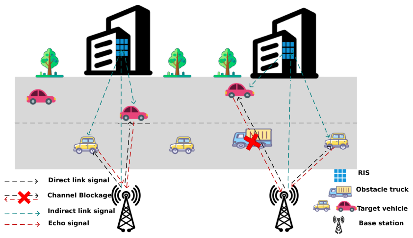
In this paper, we propose a RIS-assisted MBS scenario that includes multiple BSs, multiple RISs, and multiple vehicles, as shown in
Figure 1. The frequency bands used by different BSs are orthogonal, eliminating interference between the BSs. Each BS exclusively receives the corresponding RIS signal, and the BSs share information through time synchronization managed by a control center. We directly adopt a number of widely used clock synchronization techniques in this paper [
37].
, , denote the RIS set, the BS set, and the vehicle set, respectively. Each BS is integrated with an RIS. Considering the deployment heights of the BS and the RIS, the links between the BS and the RIS are not affected by the obstacles. The BS is equipped with a specific number of transmit and receive antennas, which can be expressed as , and , and satisfy . The number of RIS elements are, respectively, denoted as .
3.1. The Association Model Between BSs and Vehicles
The association between BSs and vehicles is represented by the association matrix
[
34]
represents the association vector of the
k-th vehicle with all BS, defined as
, implies that each vehicle is exclusively served by one BS and only one BS.
represents the association coefficient between the
k-th vehicle and the
b-th BS.
indicates an association, and
indicates no association. For each vehicle, the BS associated with it over a period of time can be represented as
represents the association within the
t-th time slot, the index of the BS associated with the
k-th vehicle,
.
If the association matrix at a given time differs from that of the previous time, it indicates BS switching. Therefore, the number of BS switches for this vehicle during the time period can be denoted as
satisfies the following condition:
and represent the association vector of BS b and the number of vehicles it serves. In this paper, BS b serves the vehicles in the set .
3.2. Communication Model
During each time slot, the BS sends ISAC signals to the served vehicles [
33], represented as
represents the beamforming transmitted by BS
b to the
k-th vehicle, and
represents the data symbol to be transmitted.
represents the transmission matrix of BS
b.
represents the data symbol transmitted by BS
b, and it satisfies the constraint
[
39].
The communication signal that the
k-th vehicle receives from the serving BS
b can be formulated as
represents the noise signal, which follows the distribution of
.
refers to the cascaded channel matrix linking the BS and the vehicle, and is represented as
represents the blocking coefficient for the link between the BS and the
k-th vehicle, when the channel is not blocked
, and when it is blocked by obstacles
.
represents the channel matrix for the BS-vehicle link, can be expressed as
d and
represent the distance between elements and the wavelength of the signal, respectively.
denotes the angle of departure between the serving BS and the
k-th vehicle, and
is the channel gain from BS
b and the
k-th vehicle [
40]. They can be represented as follows:
represents the distance from the serving BS
b and the
k-th vehicle,
denotes the path loss factor for the link of serving BS
b and the
k-th vehicle, and
represents the path loss at
m.
represents the channel matrix between the serving RIS
r and the
k-th vehicle, which can be stated by
represents the angle of arrival between the serving RIS and the
k-th vehicle, and
signifies the channel gain of the link between the RIS and the
k-th vehicle, which is shown as
represents the distance from RIS
r to the
k-th vehicle, and
denotes the path loss factor between RIS
r and the
k-th vehicle.
represents the matrix representing the phase shift of the
r-th RIS, and is indicated as
The reflection coefficients that satisfy the unit modulus constraint
.
represents the channel matrix between BS
b and RIS
r.
In this paper, this channel is modeled as a Rician channel [
39]
represents the Rician factor.
represents the NLOS component, which is modeled as a circularly symmetric complex Gaussian random variable with zero mean, where both the amplitude and phase are random.
represents the LOS component and is stated as
and
represent the transmit steering vector from BS
b to RIS
r and the receive steering vector from RIS
r to BS
b, respectively. Expressed as
Thus, the SINR at the receiver of the
k-th vehicle can be written as
The interference received by vehicle
k mainly comes from other vehicles served by the same BS
b. Since orthogonal frequency bands are used between BSs, the interference from non-serving BSs to the vehicle is not considered in this formula. The total communication rate of all vehicles in this scenario can be obtained as
3.3. Sensing Model
After the BS sends downlink communication signals to the vehicles, it will receive echo signals bounced back from the vehicles. Owing to the substantial path loss associated with multiple reflection paths through the RIS, we only consider the direct reflection path. This assumption is consistent with mmWave IoV scenarios, where high path loss and strong directionality cause most of the received power to concentrate in the LOS and the strongest NLOS component, while other weak reflections are typically 15–20 dB lower and can be neglected. Moreover, the RIS phase matrix is designed to focus the reflected energy toward the dominant path direction, making the equivalent channel effectively single-path dominated. Nevertheless, the proposed optimization framework can be readily extended to multipath channels by introducing independent angle and gain parameters for each path. When the LOS link is not blocked, the signal reflected back to the BS
b from the
k-th vehicle it serves can be written as [
14]
represents the time delay of the echo signal reflected from the
k-th vehicle to the BS, where
is the sensing channel fading coefficient from the BS to the
k-th vehicle [
41], and can be expressed as
represents the Radar Cross Section (RCS), and
represents the Doppler shift of the echo signal from the
k-th vehicle, expressed as
represents the velocity of the
k-th vehicle,
represents the carrier frequency, with
c representing the speed of light.
and
stand for the transmit and receive steering vectors at the BS, respectively, and are expressed as
represents the echo noise signal, which follows the distribution of
, where
represents the noise variance.
3.4. Inter-BS Switching Model
Initialization Phase: The BS establishes a connection with the vehicles by transmitting pilot signals and determines their initial positions using beam scanning technology [
42].
ISAC Signal Transmission: After determining the position of the vehicles, the BS transmits ISAC signals to them. This technology enables simultaneous downlink communication and sensing, allowing real-time acquisition of the motion state of the vehicles and Channel State Information (CSI). The echo signal is shown in Equation (
19).
BS Switching Decision: The BS obtains vehicle motion status and position prediction information by analyzing the echo signals, and evaluates whether an inter-BS switching decision is necessary. If the result indicates that a switch is required, the current serving BS transmits a signal to notify the next BS that it is ready to communicate with the vehicle. The switching decision process of the BS can be represented as
p represents the switching decision index, where
indicates no switching and
indicates an inter-BS switching. On the right side of the expression,
v represents the current travel direction of the vehicle,
represents the angle between the BS and the vehicle.
represents the channel blockage coefficient,
E represents the communication rate, and
is a decision function that comprehensively considers multiple factors to determine whether to perform the BS switching.
Although orthogonal frequency bands are allocated to different base stations (BSs) to eliminate inter-cell interference, the multi-BS (MBS) scenario still differs essentially from the single-BS (SBS) case. Specifically, the MBS architecture provides multiple candidate links for each vehicle, enabling dynamic BS switching when the current link experiences blockage or degradation, thereby ensuring continuous and reliable communication. Moreover, MBS systems allow cooperative beamforming and RIS control among BSs, extending the coverage area and improving sensing accuracy. In addition, the handover frequency and decision strategy under high-mobility conditions represent a dynamic optimization challenge that does not exist in the SBS case. Therefore, the focus of this work is on cooperative sensing and dynamic switching among multiple BSs rather than interference mitigation through spectrum reuse.
3.5. Problem Formulation
We define a problem that aims to maximize the communication rate while minimizing the BS sensing error and the number of BS switches. Where
,
, and
represent the weighting values for communication, sensing, and the number of switches, respectively. This objective is set to balance communication performance, sensing accuracy, and the number of BS switching, ensuring that the IoV system can accurately sense the state of the vehicles and minimize switching while transmitting data. We have
C1 ensures that the communication rate of each vehicle meets the minimum communication threshold
. C2 requires that the sensed angle error of the vehicle relative to the BS stays within the maximum threshold
. Specifically, the sensing error is formally defined as the Absolute Angular Error between the estimated and true angles. Note that this error is minimized independently via the LSTM loss function rather than the DDPG reward. C3 ensures that the link status switches only between blockage and connectivity. C4 constrains the phase shift matrix of the RIS, ensuring that its absolute value is always 1. C5 limits the total transmission power of the BS, ensuring it does not exceed the maximum threshold
. C6 indicates that each vehicle communicates with only one BS at any given time. C7 ensures that the number of vehicles served by each BS is non-negative.
4. Proposed Algorithm
We model the problem as an MDP, which primarily consists of the following key elements: an agent, a set of environmental states, a reward function, and a set of actions. This paper proposes two improved DDPG-based algorithms to solve this problem. The MFD-DDPG focuses on reducing switching frequency by considering signal strength and blockage conditions, while the MDCA-DDPG integrates both discrete and continuous actions to achieve optimal beamforming. In the V2X, CSI exhibits significant time-varying characteristics due to the high-speed mobility of vehicles and the complex propagation environment. In order to improve the reliability of the communication system, this paper adopts the LSTM network to construct a CSI prediction model, which realizes the accurate estimation of the dynamic channel by capturing the time-dependent characteristics of the channel parameters, so as to provide the system with accurate CSI assistance.
4.1. LSTM-Based Prediction Algorithm
LSTM is an improved recursive network that bridges historical information and current tasks. In this research, vehicles are constantly moving, and the channel state changes dynamically with their movement. The historical information is defined as a time-dependent dynamic sequence when predicting the position information for the next time. This sequence is the input of the LSTM along the forward chain structure and can be interpreted as
represents the duration of the time series—the time span considered for each dynamic sequence.
represents the set of all vehicle states in the IoV at time
t,
denotes the input information of the LSTM network for the
k-th vehicle, which mainly includes the following:
We use the traditional LSTM network structure, which consists of a chain of repeating modules. Each module contains several major interacting components that work together to enable the network to preserve important information while processing long-term sequential data. The first layer is the forget gate
, which primarily determines which parts of the previous cell state
will be maintained in the current state
. It incorporates the previous hidden state
along with the current input
, and calculates through the weights
,
, and
as
f represents the weights and biases of the forget gate, and
denotes the gate activation function, which is typically a this sequence is composed of the vehicle states from time
, the Sigmoid function. The forget gate helps the LSTM maintain historical information.
The input gate regulates the flow of the current input
, ensuring that only relevant content is updated into the LSTM state
. The Sigmoid function is used to implement the input gate, while the new candidate state
is generated using the tanh function. The expressions are as [
43]
i and
d represent the weights and biases associated with the input gate and the candidate memory cell state.
The output gate determines the portion of the cell state
that contributes to the output. The formula is given by
o represents the weights and biases of the output gate. Therefore, the update for the cell state
at time
t is given by
Based on the control mechanisms of the gates mentioned above, LSTM can effectively predict the next vehicle position by leveraging real-time communication information and previous state estimates. The estimated information
for the next time step, can be given by
j represents the mapping composed of a fully connected layer and an activation function. The estimated output of the LSTM at time
t is
,
. Additionally, the observed real information at this time is depicted as
,
.
Given the discrete nature of the blocking coefficient, the model adopts the Sigmoid activation function. With 0.5 set as the threshold for judgment, if the output of the Sigmoid function is greater than 0.5, it is considered that the channel is in a non-blocking state, and the blocking coefficient is set to 1. Conversely, the blocking coefficient is accordingly set to 0. In summary, the loss function needs to consider both the accuracy of position prediction and the estimation of the blocking state. This paper adopts a weighted summation method to balance the error representation of these two aspects, which can be shown as
represents the parameter set of the LSTM network;
and
are the weight coefficients used to adjust the importance of different types of errors. Algorithm 1 presents a summary of the training and application phases of the LSTM-based prediction algorithm. The proposed system adopts a “periodic sensing + continuous tracking” strategy. Initially, a full sensing stage is performed through beam scanning to estimate the vehicle angle and blockage state. Afterwards, an LSTM-based tracker predicts these parameters in subsequent time slots using historical observations, avoiding the need for sensing in every slot. When the prediction uncertainty exceeds a predefined threshold or the confidence score drops below a limit, a new sensing phase is triggered to recalibrate the estimated CSI. Hence, sensing is adaptively executed rather than slot-by-slot, significantly reducing pilot overhead while maintaining reliable tracking accuracy.
| Algorithm 1 LSTM-Based Prediction Algorithm |
- 1:
procedure TrainingProcess - 2:
Input: Dynamic CSI - 3:
Output: Optimal network parameter - 4:
Initialization: Network parameter - 5:
for each training iteration do - 6:
Sample the observed training data and input it into the network - 7:
Obtain the final layer output of the LSTM network and compute the estimated output - 8:
Calculate the loss function - 9:
Minimize the loss function to update the network parameters - 10:
end for - 11:
return trained model - 12:
end procedure - 13:
procedure
ApplicationProcess - 14:
Input: CSI and vehicle parameters from the previous 10 time slots - 15:
Output: CSI and vehicle parameters for the next time slot - 16:
for each test sample do - 17:
Input the CSI from the previous 10 time slots into the LSTM network - 18:
The LSTM network outputs the estimated value - 19:
end for - 20:
return application results - 21:
end procedure
|
4.2. Multi-Factor Decision DDPG Algorithm (MFD-DDPG)
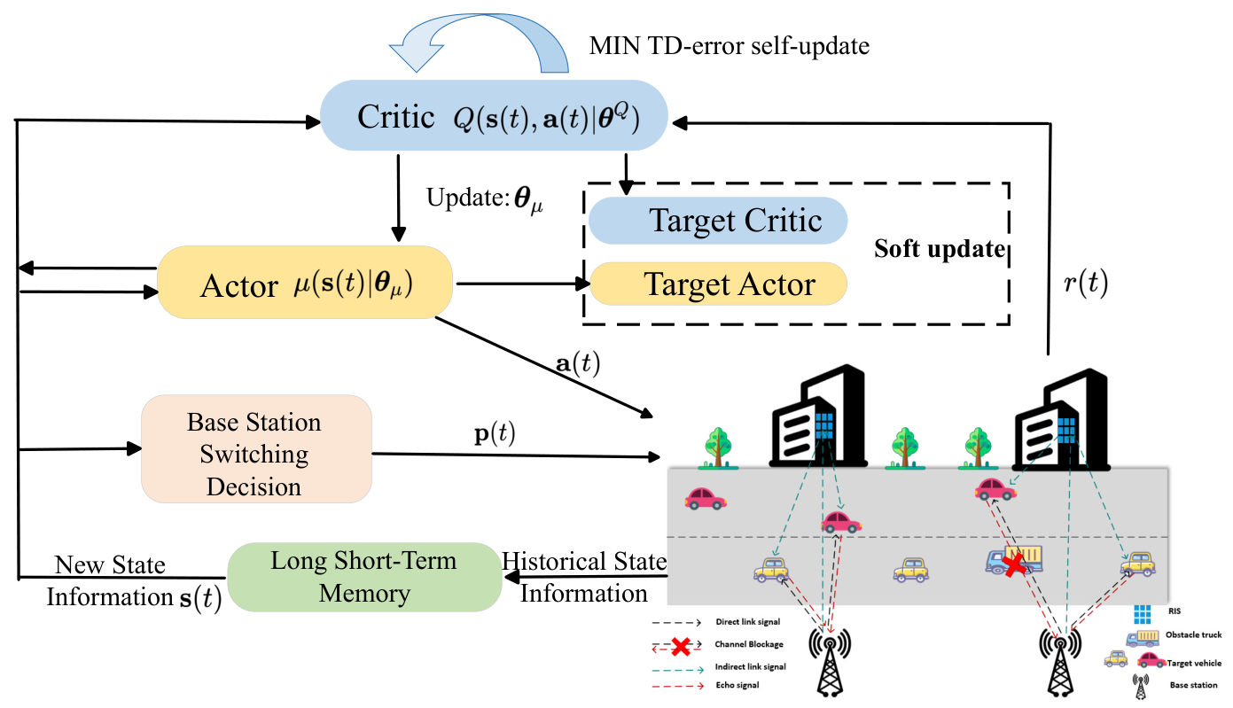
The algorithm architecture shown in
Figure 2 consists of two parts: BS switching decision and DDPG-based beamforming optimization. First, the decision of whether to switch the BS or not is made by considering the vehicle moving direction, the channel blocking condition, and the received signal strength in the IoV, based on which the beamforming and phase shift matrix design are optimized using DDPG.
The BS needs to be analyzed at each point in time to determine whether a service vehicle requires BS switching. At time
t, the communication signal received by vehicle
k from the serving BS
b is indicated as
The signal strength and communication rate of BS
b for vehicle
k can be calculated as
In addition to signal strength, this paper introduces the blockage coefficient between the BS and the k-th vehicle, as well as the travel direction coefficient of the k-th vehicle, as key considerations.
The blockage coefficient is used to describe the blockage condition of the BS-vehicle link. A blockage coefficient of 1 indicates that the link is not blocked, while a coefficient of 0 indicates that the link is blocked. The direction coefficient equals 1 indicates that at time t, the k-th vehicle is moving towards BS b. Conversely, the direction coefficient equals −1 indicates that the k-th vehicle is moving away from BS b.
Through this multi-factor integrated decision-making approach, it is possible to more accurately formulate a BS switching algorithm that meets the demands of the IoV. Consequently, this improves the overall communication effectiveness and dependability. Therefore, incorporating this BS switching decision algorithm into the beamforming design process allows the DDPG network to better learn strategies as the vehicle-BS association matrix changes, ultimately maximizing the total performance of the communication system. The complete algorithm steps are presented in Algorithm 2.
| Algorithm 2 Training procedure of the MFD-DDPG algorithm |
- 1:
Input: LSTM-optimized policy, network configuration, and minimum switching threshold . - 2:
Output: Actor and Critic network parameters , , and the optimal switching policy. - 3:
Initialization: Clear the experience replay buffer and initialize the network parameters and . - 4:
for each episode do - 5:
Reset the relationship state among the RIS-assisted IoV system, the vehicle, and the BS. - 6:
for each step do - 7:
Use the LSTM network to predict the channel state and vehicle state at the next time step. - 8:
Obtain the current state and action , add exploration noise, calculate the reward , and transition to the next state . - 9:
Store in the experience replay buffer . - 10:
Determine a potential switching BS with the highest reward according to the current state information, and obtain the details of the current BS and the vehicle. - 11:
Use (37) to calculate the signal strength and estimate for the vehicle at the current time step. - 12:
Initialize the switching state as . - 13:
if then - 14:
if then - 15:
if and then - 16:
Perform base station handover, ; - 17:
end if - 18:
else - 19:
if and then - 20:
Perform base station handover, ; - 21:
else if then - 22:
Perform base station handover, ; - 23:
end if - 24:
end if - 25:
end if - 26:
Update the Critic and Actor networks, and softly update the target networks. - 27:
end for - 28:
end for
|
4.3. Mixed Discrete and Continuous Action DDPG (MDCA-DDPG)
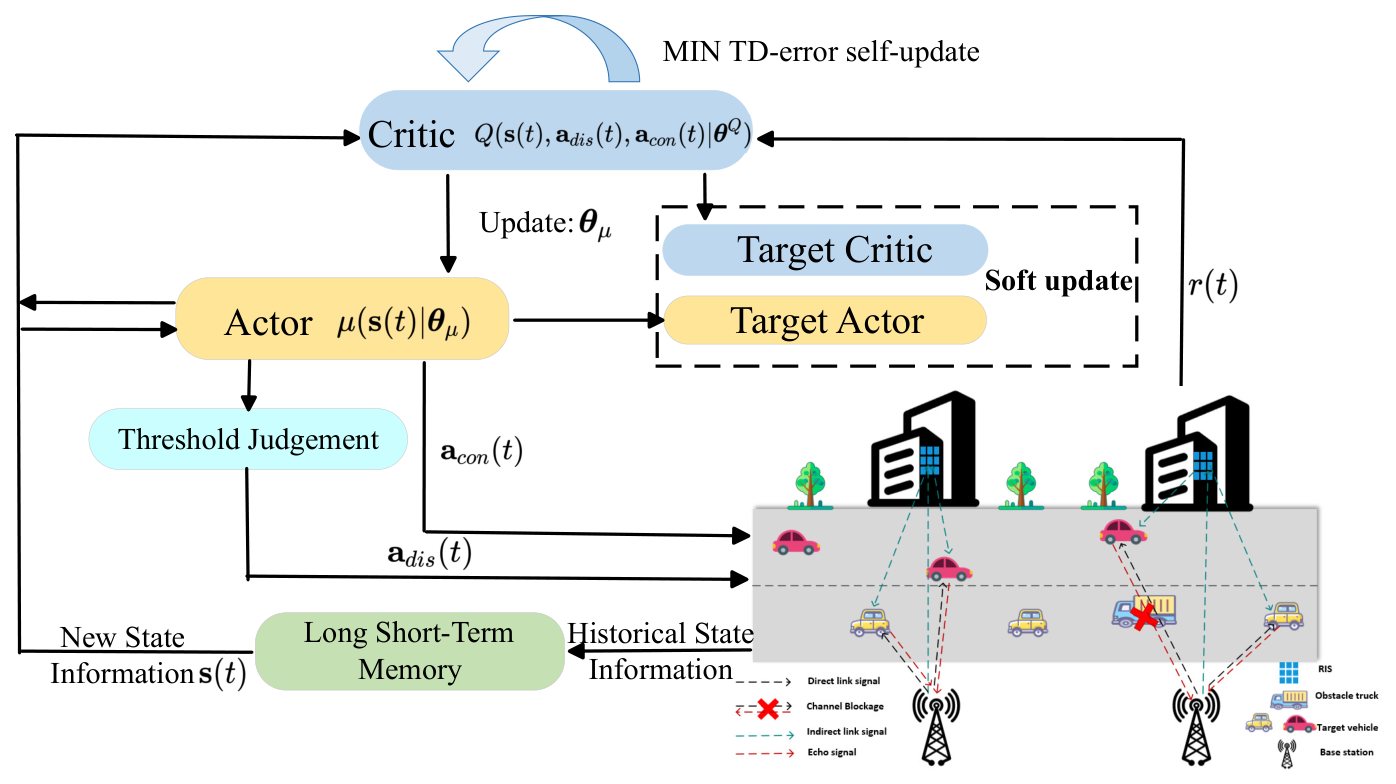
The above algorithm focuses on comprehensively considering multiple factors in each training step to decide whether BS switching is necessary. This section presents an improved algorithm called MDCA-DDPG, as shown in
Figure 3, which generates discrete and continuous actions simultaneously. DDPG is a policy-based method that can learn an optimal policy in a continuous action space. In complex IoV scenarios, the decisions faced include not only the continuous optimization but also discrete decisions such as whether to execute BS switching. The core of this algorithm lies in integrating discrete action into the action decision process. This enables a more flexible switching decision and beamforming design process.
The state space in this paper includes all channel matrices, received communication signals, sensing echo signals, the reward value from the preceding time step, and the prediction outputs of the LSTM network. It can be characterized as
represents information related to BS
b, covering the channel matrices between each serviced vehicle and the BS, the matrices between the vehicles and the serving RIS, the communication signals received by the vehicles, and the echo signals detected at the BS. It can be represented as
Based on the aforementioned state information, the Actor network provides action outputs. Specifically, in the algorithm implementation, the MDCA-DDPG processes the decision-making for both discrete and continuous actions through the Actor network. The discrete action component is determined by the output of the Actor network using a specific threshold. This threshold is used to map the output of the network into a discrete action space, the BS switching decision. Since the output values are normalized by the tanh activation function during the implementation of the Actor network, this mapping can be performed based on the sign of the output values, with a discrete action set to 1 (base station switching) when the output is greater than 0, and a discrete action set to 0 (no switching) when the output is less than 0.
For continuous action, the Actor network outputs a value directly, which is also normalized by the tanh activation function to ensure that the output action is within the appropriate range. These continuous action values are then used to adjust continuous control variables such as beamforming parameters. This hybrid action output mechanism allows MDCA-DDPG to flexibly handle complex problems of BS switching and communication optimization in IoV.
The Actor network produces an action vector
as its output that includes both discrete action
and continuous action
. Therefore, the output model of the Actor network can be represented as
represents the ongoing condition of the environment, and
represents the parameters of the Actor network policy. The discrete action
is output by the Actor network and then undergoes a threshold decision to determine whether the vehicle should perform a BS switching. It is represented as
The continuous action
is directly output by the Actor network, representing the beamforming associated with all BSs, as well as the RIS matrix for phase shift. It is depicted as
The Critic network is used to assess the current policy, providing the expected return given the , , and . The input of the Critic network also needs to consider both discrete and continuous actions, and can be represented as , where represents the Critic network parameters.
In this study, it is necessary to achieve better communication and sensing performance while minimizing the number of switches. Therefore, the reward function must consider these factors, as well as the power limit and the lowest communication threshold, to meet the hardware limit of the BS and ensure the stability of communication. The reward function is set as
The reward function comprehensively considers the performance evaluation of both discrete and continuous actions. The first three terms represent continuous action, while the fourth term represents discrete action.
,
,
, and
represent the weight distribution of each part of the reward.
reflects the communication penalty. If the communication rate of a vehicle falls below the threshold, the reward function imposes a penalty as
The limitation on the transmission power is also constrained by the reward function to ensure that the total transmission power does not surpass the maximum allowable threshold, which can be expressed as
represents the total number of current BS switching. The purpose is to reduce the number of switches as much as possible. In this way, the aim is to enhance communication performance while minimizing the number of switches and ensuring that the power remains within an acceptable range, thereby maintaining the stability of the communication connection. A penalty is imposed whenever a switch occurs. The precise steps of training the MDCA-DDPG are provided in Algorithm 3.
To avoid optimization bias caused by differences in the magnitude of various physical quantities, we normalized each sub-objective in our implementation, expressed as
,
,
and
.
| Algorithm 3 Training Procedure of the MDCA-DDPG Algorithm |
- 1:
Input: LSTM-optimized output strategy and network parameters. - 2:
Output: Optimal Actor and Critic network parameters and , and the optimal switching decision. - 3:
Initialization: Clear the experience replay buffer and initialize the network parameters and . - 4:
for each episode do - 5:
Reset the RIS-assisted MBS-IoV system and randomly initialize the association state between vehicles and BSs. - 6:
for each step do - 7:
Use the fully trained LSTM network to predict the channel state and vehicle state at the next moment. - 8:
Observe the current state , feed it into the Actor network, and identify the candidate BS q closest to the vehicle. - 9:
The Actor network outputs the hybrid action , where determines whether to switch from the current BS b to the candidate BS q, and is used for beamforming design. Exploration noise is added to . - 10:
Based on the switching decision and hybrid beamforming design at the BS, the agent calculates the current reward by jointly considering the performance of the discrete and continuous actions. - 11:
After executing the action , the agent transitions to the next state and stores in the experience replay buffer . - 12:
Sample mini-batches from , update the Critic and Actor networks by minimizing the loss function, and softly update the target networks. - 13:
end for - 14:
end for
|
5. Numerical Results
The road center is defined as the coordinate origin (0 m, 0 m) to establish a coordinate system. It is assumed that there are
K vehicles traveling along the x-axis, with their initial positions randomly determined and represented as
to
. The noise level is set to −80 dBm. The parameters used in the simulation are shown in
Table 1.
First, we explore the consequences of different BS numbers on a single-vehicle scenario. Describe the single-vehicle scenario as SU, the multi-vehicle scenario as MU, the single-base station as SB, and the multi-base station as MB. The power constraint is set to 27 dBm. Each BS has 32 antennas, while each RIS contains 96 elements. The vehicle is initially positioned at (−100 m, 0 m), with BSs located at (−50 m, −50 m) and (50 m, −50 m). The RIS positions are set at (−50 m, 50 m) and (50 m, 50 m).
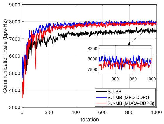
Figure 4 shows that the communication rate in the MB scenario is significantly higher than that in the SB scenario due to the larger coverage area. In the MB, the performance achieved by the proposed MFD-DDPG and MDCA-DDPG is similar, and as the iterations progress, the communication rate gradually increases and tends to stabilize. Because MFD-DDPG primarily determines BS switching based on signal strength, it makes a switching decision once the signal strength of a candidate BS is greater. On the other hand, MDCA-DDPG employs a hybrid action approach to enable the BS to make switching decisions while jointly optimizing beamforming strategies based on the overall environment.
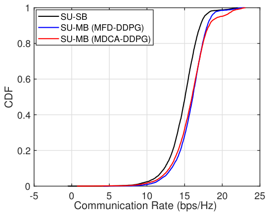
We use the cumulative distribution function (CDF) to represent the communication performance after convergence. As shown in
Figure 5, in the MB scenario, the performance of both algorithms is nearly the same, and both perform better than in the SB scenario, especially in the higher communication rate region. This demonstrates that the performance in the MB scenario is significantly better than in the SB scenario.
Secondly, the relationship between the number of BSs in an MB system and its effect is shown in
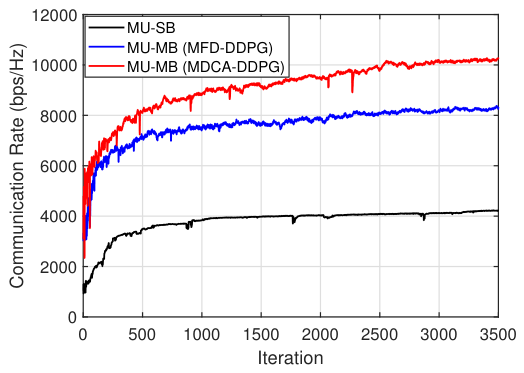
Figure 6. It is assumed that there are three vehicles with initial positions at (−100 m, 0 m), (−50 m, 0 m), and (0 m, 0 m), respectively. The number of BS antennas and RIS elements is both set to 8, and the power constraint for a single vehicle is 27.8 dBm.
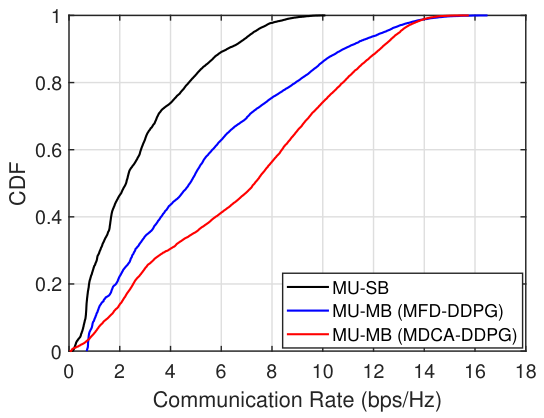
Figure 6 shows that the performance in MB scenarios is significantly better than in SB scenarios. However, the performance of the MFD-DDPG is far inferior to that of the MDCA-DDPG. In BS switching, it is not enough to consider factors such as signal strength. Interference between vehicles is also an important factor. The MDCA-DDPG meets the needs of such scenarios but also leads to more switching. According to the results after convergence, the MFD-DDPG requires only 3 switches, while the MDCA-DDPG results in as many as 25 switches after training convergence. Therefore, each of these algorithms has its own advantages. To analyze the effect of multiple BSs compared to a single BS, the communication rates of all vehicles are represented using the CDF. Each curve represents the combined communication rate distribution of all vehicles, as shown in
Figure 7.
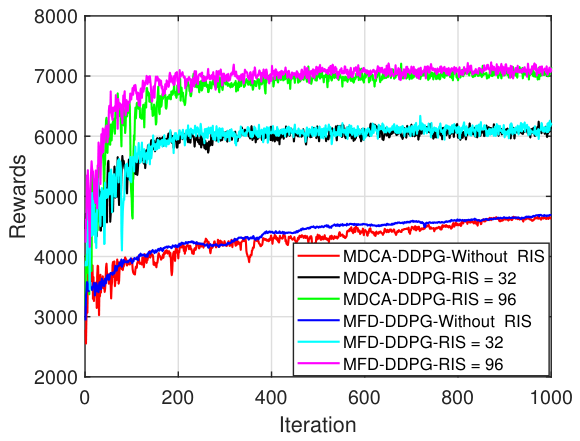
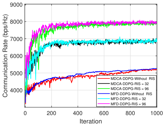
Thirdly, we investigate the effect of RIS on system performance in a dual-BS scenario, temporarily disregarding vehicle interference and link blockage. The BSs are configured with 32 antennas, and the transmission power is set to 27 dBm. The starting point of the vehicle is (−100 m, 0 m), with the BSs located at (−50 m, −50 m) and (50 m, −50 m), and the corresponding RIS positions at (−50 m, 50 m) and (50 m, 50 m). A thorough analysis is performed on the impact of having 0, 32, and 96 RIS elements on the system reward value and communication rate. As shown in
Figure 8, the system reward gradually increases and eventually stabilizes with iterations. From
Figure 9, it can be observed that as the number of RIS elements increases, the system communication rate shows an upward trend. Without RIS, the communication rates of the two algorithms are approximately 5.2 Kbps/Hz. However, with the introduction of RIS, even with 32 RIS elements, the system communication rate can reach 6.9 Kbps/Hz, representing an improvement of about 32.6%. With 96 RIS elements, the communication rate can reach as high as 8.0 Kbps/Hz, which is an improvement of over 50% compared to the scenario without RIS.
Fourth, to consider the practicality of the BS switching algorithms discussed in this paper, the proposed algorithm is compared with two other common algorithms. ‘Distance’ refers to the distance-based algorithm [
44], which performs a switch when the candidate BS is closer to the vehicle than the serving BS. ‘Block’ refers to the blockage-based switching algorithm, which performs a BS switching when the BS detects that the channel to the vehicle is interrupted. Based on these two comparison algorithms, the paper conducts a comparison of BS switching algorithms in both single-user and multi-user scenarios.
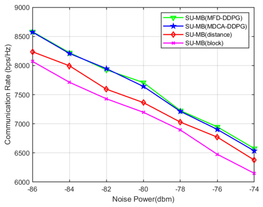
The system configuration includes 32 BS antennas, 96 RIS elements, and a transmission power of 27 dBm. The starting point of the vehicle is (−100 m, 0 m). The BSs are placed at (−50 m, −50 m) and (50 m, −50 m), with the corresponding RIS positions at (−50 m, 50 m) and (50 m, 50 m). Additionally, the paper introduces the interference of obstacles in this scenario by placing a stationary large truck with a length of 5 m at the road position (−20 m, −3 m) as an obstacle. Under these parameter settings, the paper compares the communication rate variations in these algorithms with changes in noise levels, as outlined in
Figure 10.
From the analysis, it is clear that the proposed algorithms improve communication performance by 6.25% and 5% compared to the block and distance algorithms, respectively. In this scenario, RIS is introduced to allow link reconstruction even when there is blockage. Switching to another, more distant BS due to blockage can actually degrade system performance, making the capabilities of the block-based algorithm the poorest among these options. The distance-based switching algorithm, while considering the impact of distance on communication, neglects factors such as blockage, making the resulting switching decision suboptimal as well.
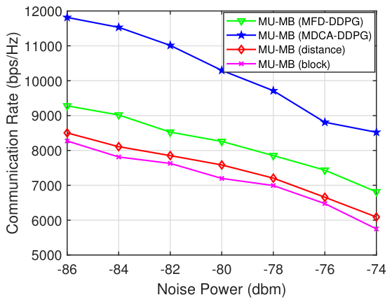
Next, simulations are conducted for a multi-vehicle scenario. The placements of the three vehicles are (−100 m, 0 m), (−50 m, 0 m), and (0 m, 0 m). The placements of the BSs are (−100 m, −50 m) and (100 m, −50 m), with the corresponding RIS positions at (−100 m, 50 m) and (100 m, 50 m). As seen in
Figure 11, the MDCA-DDPG outperforms the two benchmark algorithms by 42.2% and 39.6%, respectively. This is because the MDCA-DDPG incorporates the switching decision into the actions of the DDPG network, allowing the agent to comprehensively consider factors such as interference between multiple vehicles to make more optimal decisions. In contrast, the other three algorithms make decisions solely based on the environmental state at a given moment. Additionally, the results demonstrate that the proposed MFD-DDPG excels compared to the distance and block algorithms. This is because, unlike the other two algorithms, the MFD-DDPG takes into account more factors, such as signal strength, channel blockage, and vehicle travel direction. Specifically, the frequent handovers in MDCA-DDPG increase signaling overhead and risk network stability, making it preferable for high-throughput multimedia applications. Conversely, MFD-DDPG ensures stable connectivity with minimal overhead, making it ideal for mission-critical IoV services like autonomous driving.