Article

Coordinated Low-Voltage Ride-Through Control Strategy for Flywheel Energy Storage Systems

1
College of Energy and Power Engineering, Inner Mongolia University of Technology, Hohhot 010080, China
2
Engineering Research Center of Large Energy Storage Technology, Ministry of Education, Hohhot 010080, China
3
College of Electric Power, Inner Mongolia University of Technology, Hohhot 010080, China
*
Author to whom correspondence should be addressed.
Appl. Sci. 2026, 16(11), 5388; https://doi.org/10.3390/app16115388
Submission received: 24 April 2026 / Revised: 16 May 2026 / Accepted: 24 May 2026 / Published: 28 May 2026
(This article belongs to the Special Issue Energy and Power Systems: Control and Management)

Abstract

To address DC-link voltage fluctuation, active-power imbalance between the machine side and the grid side, and double-frequency distortion in the grid current of a flywheel energy storage system (FESS) under symmetrical and asymmetrical voltage sag faults, this paper proposes a coordinated control strategy for the machine-side and grid-side converters to enhance low-voltage ride-through (LVRT) capability. Taking the DC-side energy imbalance as the coordination criterion, the machine-side converter adopts an online active-current-command reconstruction method based on cascaded limiting of DC-link voltage deviation. Under reactive-power-priority support and constrained active-power output on the grid side, the FESS can actively adjust its active-current command according to the DC-side energy state, thereby suppressing DC-link overvoltage/undervoltage and restoring the power balance between the machine side and the grid side. On the grid side, an improved linear active disturbance rejection control (LADRC) is introduced into the current inner loop. By optimizing the structure of the extended state observer, the observation and compensation capability for double-frequency disturbances is enhanced, thus improving grid-current quality under asymmetrical faults. In this way, power rebalancing between the machine side and the grid side, DC-link voltage stabilization, and grid-current disturbance suppression are incorporated into a unified coordinated control framework. Hardware-in-the-loop experimental results show that the proposed strategy can maintain DC-link voltage stability during both symmetrical and asymmetrical voltage sags, while keeping the maximum grid-current total harmonic distortion (THD) below 0.13%. Under asymmetrical voltage sag, the improved LADRC reduces the maximum interphase peak-current deviation from approximately 52 A under conventional PI control to 4.57 A, corresponding to a reduction of about 91.2%. These results indicate that the proposed strategy can effectively enhance DC-link voltage stabilization and improve grid-current quality during faults.

1. Introduction

With the ongoing global energy transition, the large-scale integration of renewable energy has become a key trend in the evolution of modern power systems [1]. As one of the world’s largest markets for renewable energy deployment, China had, by the end of 2025, accumulated more than 1800 GW of installed wind and photovoltaic capacity, accounting for 47.3% of its total installed power generation capacity. At the same time, the installed capacity of newly deployed energy storage systems in operation nationwide reached 136 GW/351 GWh. New energy storage is therefore emerging as an important infrastructure for facilitating renewable energy integration and enhancing the regulation capability of power systems. Compared with electrochemical energy storage technologies, flywheel energy storage systems (FESSs) offer distinct advantages, including high power density, fast response, long cycle life, and environmental friendliness [2,3]. Accordingly, FESSs have shown considerable potential in high-frequency power regulation, short-term inertial support, and transient support during faults [4,5]. With the continued advancement of FESS demonstration projects and standardization efforts, grid-connected operation under complex grid-fault conditions—especially low-voltage ride-through (LVRT) capability—has become a key factor limiting the wider deployment of FESSs.
Existing LVRT studies mainly follow two technical routes, namely hardware-assisted methods and control-oriented methods [6,7]. Hardware-assisted methods usually introduce energy storage or dissipation units to buffer the energy impact during faults [8,9], whereas control-oriented methods improve converter capacity utilization by optimizing current allocation, reactive power support, and power regulation strategies [10,11]. Although these studies have provided useful theoretical and technical references for fault ride-through control, most of them focus on wind turbines or wind–storage hybrid systems, while specific investigations on coordinated control between the machine-side and grid-side converters of a standalone grid-connected FESS during faults remain limited. As the role of energy storage devices in fault support continues to expand, increasing attention has also been paid to their own grid-connected operating characteristics and LVRT control under voltage sag conditions [12,13]. Relevant studies indicate that research on energy storage is gradually extending from the ride-through control of the storage device itself to its participation in fault support and transient stability enhancement of external renewable energy systems [14,15].
Owing to its rapid power response and favorable transient-support characteristics, the FESS has recently attracted growing interest in fault ride-through studies of renewable-energy systems. Existing studies have shown that the FESS can enhance the transient stability and fault support capability of wind farms and renewable energy transmission systems [16,17]. Meanwhile, some researchers have started to investigate the grid-fault ride-through performance of standalone FESSs. Zhai et al. established an early grid-connected FESS model and proposed a basic ride-through control strategy for three-phase short-circuit faults, thereby verifying the feasibility of fault support by the FESS. However, their work mainly focused on symmetrical faults, with insufficient attention given to disturbance suppression under asymmetrical faults [18]. On this basis, Zheng et al. further proposed an LVRT strategy based on coordinated machine-side and grid-side control, which is applicable to both symmetrical and asymmetrical faults and improves current tracking and reactive power support during faults. However, their study did not sufficiently address machine-side electromagnetic transients and torque impacts [19]. To overcome this limitation, Sturm et al. investigated machine-side electromagnetic characteristics and suppressed torque shock and flux fluctuations during faults through resonant current control and flux regulation [20]. At present, research on LVRT control of standalone FESSs is still at a developing stage. Existing studies mainly focus on validating basic fault-support capability and conventional coordination between the machine-side and grid-side converters. Further efforts are still needed to formulate the key issues under symmetrical and asymmetrical faults in a unified manner and to improve coordinated machine-side and grid-side control.
In summary, most existing LVRT schemes for standalone FESSs adopt a control mode that combines conventional closed-loop machine-side control with grid-side reactive power support. Under such schemes, machine-side power regulation mainly follows external commands passively, lacking active coordination and online reconstruction based on DC-side energy imbalance. Consequently, grid voltage faults can easily lead to active-power imbalance between the machine side and the grid side, resulting in DC-link overvoltage. In addition, although existing methods for asymmetrical faults have involved positive- and negative-sequence decoupling, current limiting, and power ripple suppression, relatively few studies have systematically addressed the coordination among double-frequency disturbance suppression, grid-current quality improvement, and converter capacity constraints from the perspective of grid-side current-loop disturbance rejection. Therefore, this paper investigates the coordinated LVRT control of a standalone grid-connected FESS under symmetrical and asymmetrical voltage sag faults. Based on the mathematical models of the machine-side and grid-side converters, the mechanisms of active-power imbalance between the machine side and the grid side, DC-link voltage fluctuation, and double-frequency disturbances caused by negative-sequence components during faults are analyzed, and a coordinated fault ride-through control framework for the machine-side and grid-side converters is established. Specifically, to cope with DC-side energy accumulation and DC-link overvoltage caused by reactive-power-priority support and constrained active-power output on the grid side under low-voltage faults, a coordinated regulation method based on cascaded limiting of DC-link voltage deviation is adopted on the machine side to restore the power balance between the machine side and the grid side and suppress DC-link overvoltage. Meanwhile, an improved linear active disturbance rejection control (LADRC) is introduced into the grid-side current inner loop. By optimizing the structure of the extended state observer, the observation and compensation capability for double-frequency disturbances is enhanced, thereby improving grid-current quality under asymmetrical faults. In this way, power rebalancing between the machine side and the grid side, DC-link voltage stabilization, and grid-current disturbance suppression are incorporated into a unified coordinated control objective.
The contributions of this study are summarized as follows:
(1)
A coordinated LVRT control framework for the machine-side and grid-side converters is established for standalone grid-connected FESSs. Different from conventional control methods in which the machine-side power command mainly passively follows an external reference, the proposed framework takes the DC-side energy imbalance as the coordination criterion and introduces the DC-link voltage deviation into the regulation of the machine-side active-current command.
(2)
An online reconstruction strategy for the machine-side active-current command based on cascaded limiting of DC-link voltage deviation is proposed. This strategy enables the machine-side converter to actively adjust its power response when the grid-side active-power output is constrained, thereby suppressing DC-link overvoltage or undervoltage and restoring the power balance between the machine side and the grid side.
(3)
An improved LADRC-based grid-side current inner-loop control strategy is proposed for asymmetrical voltage sags. By optimizing the linear extended state observer (LESO) structure, the proposed method enhances the observation and compensation capability for the double-frequency disturbance caused by negative-sequence components, thereby improving grid-current quality and disturbance rejection performance.
Finally, hardware-in-the-loop (HIL) experiments are conducted to verify the effectiveness of the proposed coordinated control strategy in DC-link voltage stabilization, grid-current quality improvement, and LVRT performance enhancement.

2. Grid-Connected Topology and Steady-State Control of FESS

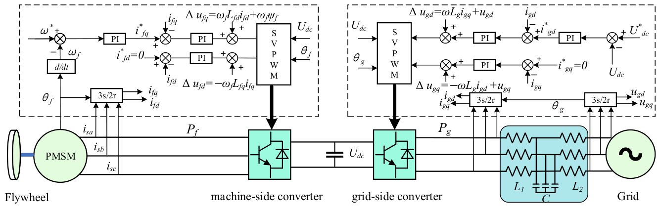
The grid-connected topology of the FESS is shown in Figure 1. It mainly consists of a flywheel rotor, a permanent magnet synchronous machine (PMSM), a machine-side converter, a grid-side converter, a DC-link capacitor, and an LCL filter [21]. The flywheel rotor is rigidly coupled to the shaft of the PMSM. The machine-side and grid-side converters form a back-to-back structure through the DC link, while the grid-side converter is connected to the AC grid through the LCL filter [22]. According to the direction of power flow, the FESS can operate in two modes: charging and discharging. In the charging mode, the grid-side converter absorbs power from the AC grid and transfers it to the machine side through the DC link, driving the PMSM to accelerate the flywheel and store energy. In the discharging mode, the flywheel releases mechanical energy, which is delivered to the grid through the machine-side and grid-side converters [23]. Under steady-state operation, the machine side is responsible for flywheel speed and electromagnetic power regulation, whereas the grid side is responsible for DC-link voltage stabilization and grid power control.
Under steady-state conditions, the machine-side converter adopts a rotor-flux-oriented vector control scheme. The q-axis current is used to regulate the electromagnetic torque and the charge/discharge power, while the d-axis current reference is set to i f d = 0. The dq-axis current inner loop of the machine-side converter employs a voltage control law with cross-coupling compensation and permanent-magnet back-EMF feedforward [24], which can be expressed as:
u f d = ( K p + K i s ) ( i f d i f d ) ω f L q i f q u f q = ( K p + K i s ) ( i f q i f q ) ω f L d i f d + ω f ψ f
where i f d and i f q are the d- and q-axis current references, respectively, i f d and i f q are the corresponding actual currents, L d   and L q are the d- and q-axis inductances of the PMSM, ψ f is the permanent-magnet flux linkage, ω is the reference value of the electrical angular speed of the machine, ω f is the electrical angular speed of the machine, and K p and K i are the proportional and integral gains of the machine-side current inner loop. Under the condition of i f d = 0 and neglecting machine losses, the machine-side electromagnetic power can be written as:
P f = 3 2 ω f ψ f i f q
which indicates that the machine-side active power is ultimately regulated through the q-axis current.
The grid-side converter adopts a double-loop control structure composed of an outer voltage loop and an inner current loop [25]. The outer loop regulates the DC-link voltage and generates the active-current reference, while the inner current loop ensures fast tracking of the grid-current reference, thereby stabilizing the DC-link voltage and regulating the grid-side active and reactive power. In the grid-voltage-oriented synchronous rotating dq reference frame, the d- and q-axis voltage equations of the grid-side converter are given by:
u g d = e d + R g i g d + L g d i g d d t ω g L g i g q u g q = e q + R g i g q + L g d i g q d t + ω g L g i g d
where U d c is DC-link voltage reference, e d and e q are the d- and q-axis components of the grid voltage, i g d and i g q are the d- and q-axis components of the grid current reference, i g d and i g q are the d- and q-axis components of the grid current, L g and R g are the equivalent grid-side filter inductance and resistance, respectively, and ω g is the synchronous angular frequency. Accordingly, the active and reactive power delivered by the grid-side converter can be expressed as:
P g = 3 2 u g d i g d + u g q i g q Q g = 3 2 u g d i g q u g q i g d

3. Conventional LVRT Control Strategy of FESS

When grid faults cause the point-of-common-coupling voltage to sag or swell, the FESS is still required to remain connected to the grid within the specified time and to provide the necessary reactive power support in accordance with fault ride-through requirements [26,27], so as to assist the grid voltage in recovering to a stable operating state.
During steady-state operation of the FESS, as shown in Figure 1, the machine-side electromagnetic power P f and the active power P g delivered by the grid-side converter satisfy the energy balance relationship:
P f P g = 1 2 C d U d c 2 d t
where U d c is the voltage across the DC-link capacitor, and C is the DC-link capacitance. When the machine-side power and grid-side power are balanced, i.e., P f P g , the DC-link voltage remains stable. During a grid voltage sag, if the FESS operates in the discharging mode, the power imbalance caused by the fault leads to an increase in the DC-link voltage; conversely, if the system operates in the charging mode, the power imbalance causes the DC-link voltage to decrease. Considering the voltage withstand capability of the converters and DC-link components, the upper and lower protection thresholds of the DC-link voltage are set to 1.1 pu and 0.9 pu of the rated value, respectively.

3.1. Machine-Side Control Strategy During Grid Voltage Faults

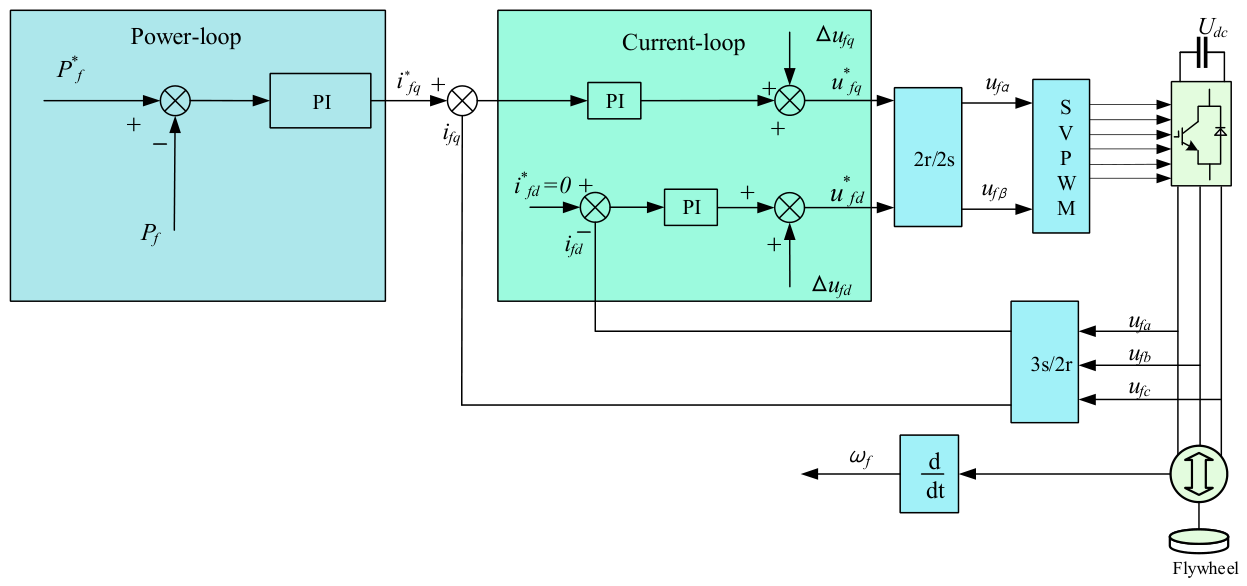
When the grid voltage sags, the active power output capability of the grid-side converter decreases, resulting in a transient imbalance between the machine-side electromagnetic power and the grid-side active power, which further causes DC-link voltage fluctuations [28]. For a standalone FESS, the core objective of machine-side control during faults is to rebalance the power between the machine side and the grid side by regulating the electromagnetic power, thereby suppressing DC-link overvoltage. To this end, the machine-side converter adopts a power outer-loop and current inner-loop control strategy, as shown in Figure 2.
According to the machine-side power relationship in Section 2, under rotor-flux-oriented control and with i f d = 0 , the q-axis reference current of the machine side can be obtained from the output of the power outer loop as:
i f q = 2 3 ω f ψ f K p + K i s P P f
where P f is the machine-side power reference, K p and K i are the proportional and integral gains of the power outer loop, respectively. It can be seen that the regulation of machine-side active power is ultimately achieved through the q-axis current reference command.
The machine-side controller parameters are tuned according to the bandwidth-separation principle of “fast tracking in the current inner loop and slow regulation in the power outer loop”. The current inner loop is designed using the pole-zero cancelation method. After voltage feedforward and cross-coupling compensation, the d- and q-axis current channels can be approximately regarded as first-order plants in the form of 1 / ( L s + R ) , where L and R denote the equivalent inductance and equivalent resistance of the corresponding axis, respectively. By matching the zero of the PI controller with the pole of the controlled plant, the proportional gain and integral gain can be determined as K p = L ω c i and K i = R ω c i , respectively, where ω c i is the desired current-loop bandwidth. The bandwidth of the power outer loop is set lower than that of the current inner loop. Its PI parameters are initially tuned according to the relationship between the electromagnetic power and the q-axis current, and are further verified and corrected through simulation and HIL experiments to ensure the dynamic response and smoothness of the power regulation process.

3.2. Grid-Side Control Strategy During Grid Voltage Faults

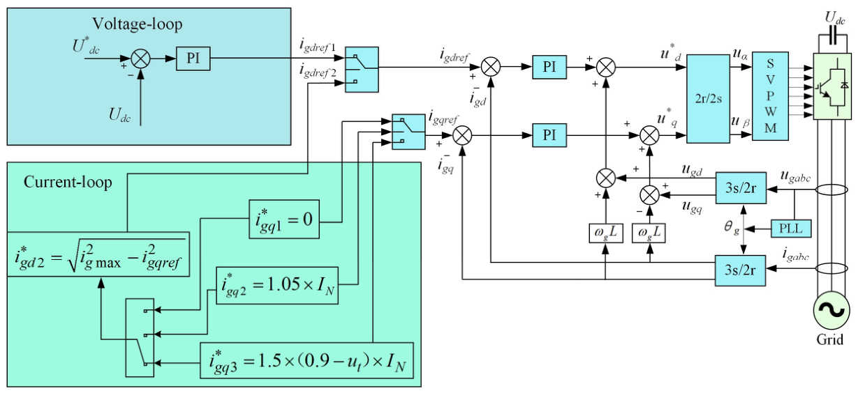
During steady-state operation, the grid-side converter adopts a grid-voltage-oriented vector control scheme to maintain the stability of the DC-link voltage. According to the grid-side power relationship in Section 2, the d-axis current determines active power exchange, while the q-axis current determines reactive power output. Therefore, under LVRT conditions, the control of the grid-side converter is constrained not only by the energy balance requirement on the DC side of the system, but also by grid connection codes. The control scheme of the grid-side converter is shown in Figure 3.
According to the voltage sag depth at the point of common coupling, the relationship between the reactive current required for voltage recovery and the voltage sag depth [29,30,31] is given by:
i g r e f = 0 ( u t > 0.9 ) , i g r e f = 1.5 × ( 0.9 u t ) × I N ( 0.9 u t 0.2 ) , i g r e f = 1.05 × I N ( u t < 0.2 ) .
where u t is the per-unit voltage at the point of common coupling, and I N is the rated current of the converter. When the voltage at the point of common coupling drops deeply, the converter capacity of the grid-side converter limits the active-current output, and the maximum allowable active-current reference can be expressed as:
i g d r e f 2 = i g max 2 i g q r e f 2
where i g m a x is the maximum current magnitude allowed for the grid-side converter output. The DC-link voltage deviation is regulated by a PI controller to obtain the active-current reference   i g d r e f 1 . The active-current limit i g d r e f 2 is calculated from (8), and the smaller one is selected as the active-current output command of the grid-side converter. When i g d r e f 1 < i g d r e f 2 , the DC-link voltage can be kept stable by the outer-loop control alone. When i g d r e f 1 > i g d r e f 2 , the active-power output of the grid-side converter is limited by the converter capacity. In this case, the DC-link voltage cannot be effectively restored by grid-side control alone; therefore, coordinated regulation between the machine-side and grid-side converters is required.
The tuning method of the grid-side PI controller parameters is similar to that of the machine-side controller. The PI parameters of the grid-side current inner loop are determined using a method that combines pole-zero cancelation and bandwidth design. The proportional and integral gains are initially selected according to the equivalent inductance L g , equivalent resistance R g , and desired current-loop bandwidth of the grid-side filter. After the current inner loop is stably tuned, the grid-side DC-link voltage outer loop is further designed with a bandwidth lower than that of the current inner loop, so as to avoid current shocks and DC-link voltage oscillations caused by overly rapid variations in the active-current reference generated by the outer loop. The final PI parameters are verified through simulation and HIL experiments by considering current limiting, DC-link voltage fluctuation, and the fault-switching process.

4. LVRT Control Strategy of FESS Based on DC Voltage Deviation Control and Improved LADRC

4.1. Machine-Side Power Regulation Strategy Based on DC Voltage Deviation

According to Equations (4) and (5), when the grid voltage drops, the active power output capability of the grid-side converter decreases significantly, resulting in an instantaneous power mismatch between the machine-side electromagnetic power P f and the grid-side active power P g , which further causes DC-link voltage fluctuation. The machine-side active power command mainly depends on a fixed power reference or a slowly varying external command, making it difficult to respond promptly to the energy imbalance at the initial stage of the fault. If the instantaneous grid-side power signal is directly used as the machine-side reference, the transient fault fluctuation may be coupled into the machine-side regulation process, thereby aggravating electromagnetic torque oscillation.
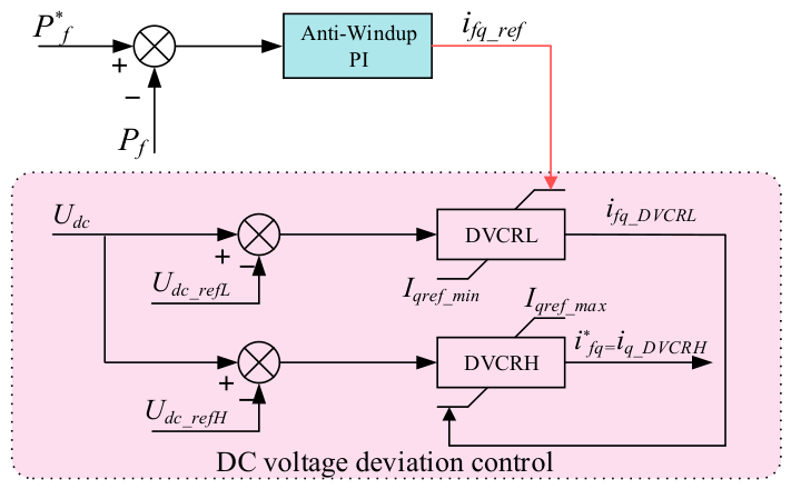
Based on the above analysis, the real-time grid-side power, which is susceptible to fault transients, is no longer used as the machine-side reference in this paper. Instead, while retaining the steady-state regulation function of the original power outer loop, a fast coordination channel reflecting the degree of DC-side energy imbalance is introduced into the q-axis active-current command. Accordingly, a machine-side coordinated control strategy based on cascaded limiting of DC-link voltage deviation is proposed, and its control block diagram is shown in Figure 4.
In Figure 4, DVCRH and DVCRL denote the high-voltage coordinator and the low-voltage coordinator, respectively. Both are regulated by anti-windup PI controllers, and their outputs, i f q , D V C R L and i f q , D V C R H are subject to upper and lower limits. The upper and lower limits of the DVCRH output are I q r e f _ m a x and I q r e f _ m i n , corresponding to the maximum and minimum currents allowed by the machine-side converter. The DVCRH output is taken as the adjusted q-axis reference current command, with its lower limit determined by the DVCRL output, whereas the upper limit of the DVCRL output is determined by the power outer loop. Therefore, the output logic of the active reference current generated by the deviation controllers can be written as:
i f q = sat i f q , D V C R L , I q , max i f q , D V C R H
where I q , m a x is the maximum q-axis current allowed for the machine-side converter, and sat (⋅) denotes the saturation function. To avoid directly introducing grid-side transient disturbances into the machine side, the machine-side power reference is latched to its steady-state fixed value during the fault. When U d c < U d c _ r e f L , it indicates insufficient input energy on the DC side. In this case, the output of DVCRH remains at its lower limit, while DVCRL comes out of saturation and resumes integral regulation. Since the lower limit of DVCRH is determined by DVCRL, the final current reference command is taken over by DVCRL, which compensates the transient energy deficit by generating a negative compensation current, thereby rebalancing the machine-side and grid-side power and stabilizing the voltage at the lower limit U d c _ r e f L . When U d c > U d c _ r e f H , it indicates that the power injected from the machine side into the DC side exceeds the power that can be delivered by the grid side. In this case, DVCRL remains saturated at its upper limit i f q _ r e f , while DVCRH instantaneously exits saturation and starts reverse regulation. Since DVCRH directly determines the final output of the command in the multi-level nested limiting structure, the high-voltage coordinator actively reduces the machine-side active-current command, thereby restricting excessive energy flow into the DC side, rebuilding the dynamic balance between the machine side and the grid side, and clamping the DC-link voltage at the upper limit U d c _ r e f H . Therefore, when a grid fault causes the DC-link voltage to exceed its preset limits, the high-voltage and low-voltage coordinators respond rapidly. Through the two-layer command generation mechanism of “power base value + voltage-deviation limiting”, the machine-side coordinated control preserves the original power control characteristics under normal operating conditions and automatically switches to a DC-link-voltage-priority mode when the preset voltage limits are exceeded during faults, thereby taking both steady-state control accuracy and transient fault response speed into account.
The PI parameters of DVCRH and DVCRL in Figure 4 are further verified based on the tuning results of the power outer loop and corrected together with the limiting and anti-windup mechanisms. In this way, the coordination controllers intervene only when the DC-link voltage exceeds the preset thresholds, while ensuring smooth control commands during fault transitions.

4.2. Grid-Side Current Control Strategy Based on Improved LADRC

The machine-side coordinated control mainly addresses the rebalancing of DC-side power during faults. Under asymmetrical voltage sags, however, the grid-side converter must also cope with current distortion and power pulsation caused by grid imbalance [32]. The conventional PI current inner loop has limited capability in suppressing periodic disturbances, making it difficult to simultaneously ensure dynamic response and current quality. To improve current tracking performance and enhance the fault ride-through capability under asymmetrical faults, an improved LADRC is adopted in the grid-side current inner loop to replace the conventional PI controller [33].
The core idea of LADRC is to treat all factors outside the standard system form as a lumped disturbance and to perform online estimation and feedforward compensation through an ESO [34]. Taking a first-order system as an example, its standard form can be expressed as:
x ˙ 1 = f x 1 , γ t , t + b u y = x 1
where x 1 is the state variable, b is the system parameter, u is the control input, y is the control output, γ ( t ) represents the external disturbance, and f ( ) denotes the lumped disturbance.
In the synchronous rotating reference frame, the d- and q-axis components of the grid-side current of the flywheel energy storage system are given by:
L d i g d d t = u g d R i g d + ω g L i g q e g d L d i g q d t = u g q R i g q ω g L i g d e g q
where e g d and e g q are the d- and q-axis components of the grid voltage at the point of common coupling, and R and L are the equivalent resistance and inductance of the grid-side filter. Under unbalanced grid-voltage conditions, the three-phase unbalanced voltage and current can be separated into positive- and negative-sequence components by the delayed signal cancelation (DSC) method [35]. In the synchronous rotating dq frame, the positive-sequence component appears as a DC quantity, whereas the negative-sequence component appears as an AC quantity at twice the fundamental frequency, which can be expressed as:
e g d e g q = E g d 0 E g q 0 + E d 2 ω cos ( 2 ω t ) + E q 2 ω sin ( 2 ω t ) E d 2 ω sin ( 2 ω t ) + E q 2 ω cos ( 2 ω t )
where E g d 0 and E g q 0 are the DC components generated by the positive-sequence voltage, and E g d 2 ω and E g q 2 ω are the amplitudes of the double-frequency oscillatory components generated by the negative-sequence voltage. It follows from (12) that, due to the cross-coupling characteristic and the asymmetrical voltage, double-frequency AC distortion terms are also induced in the d- and q-axis currents on the grid side. If a PI controller is still adopted, it can only achieve zero steady-state error tracking for DC quantities and is therefore unable to effectively regulate the AC components.
Accordingly, (11) can be further rewritten into the first-order extended-state form as:
z ˙ 1 = z 2 + β 1 ( i g d z 1 ) + b 0 u g d z ˙ 2 = β 2 ( i g d z 1 )
where
f d = R L i g d + ω i g q 1 L e g d + 1 L b 0 u g d f q = R L i g q ω i g d 1 L e g q + 1 L b 0 u g q
In (14), b 0 is the estimated input gain of the controlled plant. As can be seen from (13), the generalized lumped disturbances f d and f q mainly consist of the equivalent impedance voltage drop, current-loop coupling terms, parameter perturbations, and known external disturbances containing double-frequency voltage components. Therefore, the current distortion under asymmetrical faults can be uniformly transformed into a problem of lumped disturbance observation and compensation. Taking the grid-side d-axis current as an example, a first-order LESO is constructed as follows:
z ˙ 1 = z 2 + β 1 ( i g d z 1 ) + b 0 u g d z ˙ 2 = β 2 ( i g d z 1 )
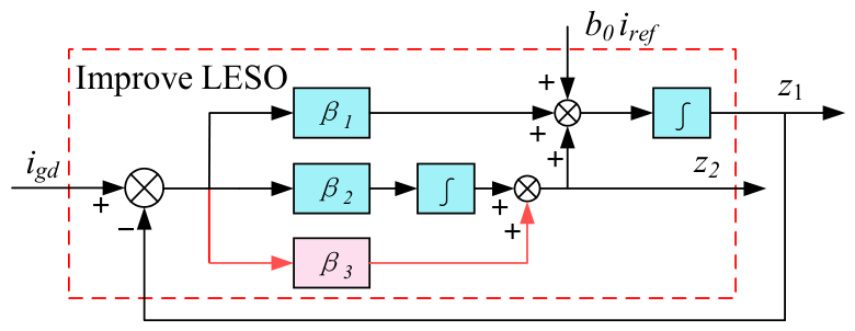
where z 1 and z 2 are the estimated values of the grid-side current and the lumped disturbance, respectively, and β 1 and β 2 are the observer gains. As can be seen from (15), the state estimates z 1 and z 2 of the LESO are both regulated by the estimation error e 1 in a negative-feedback manner. This regulation mechanism essentially reflects the passive nature of disturbance observation, and the observer gain usually needs to satisfy β 2 β 1 to compensate for the insufficient tracking capability. However, since the lumped disturbance contains severe double-frequency alternating components, the passive integral regulation mechanism of the LESO under limited gain cannot simultaneously guarantee observation bandwidth and phase margin. Therefore, an additional proportional branch β 3 is connected in parallel in the feedback loop of LESO disturbance estimation to improve the utilization of the estimation error e 1 , as shown in Figure 5.
The improved LESO is then constructed as follows:
z ˙ 1 = z 2 + β 1 ( i g d z 1 ) + b 0 u g d z ˙ 2 = β 2 e 1 + β 3 ( i ˙ g d z ˙ 1 )
The characteristic equation of the improved LESO is given by:
λ ( s ) = s 2 + ( β 1 + β 3 ) s + β 2
Letting it satisfy the desired characteristic equation yields:
β 2 = ω 0 2 β 1 + β 3 = 2 ω 0
where ω 0 is the observer bandwidth. For convenient parameter tuning, β 1 = β 3 = ω 0 is selected. If the disturbance estimation is accurate, the system is equivalently compensated into a first-order integral plant, and the state error feedback control law is given by:
u g d = k p i g d z 1 z 2 b 0
where i g d is the reference current command generated by the voltage outer loop, and k p is the gain of the linear state error feedback (LSEF).

4.3. Frequency-Domain Characteristic Analysis of the Improved LADRC Strategy

Since the inner current loops of the d- and q-axes share the same controller structure and parameter design, the d-axis is taken here as an example to analyze the frequency-domain characteristics of the improved LADRC. The key to disturbance compensation in LADRC lies in whether the LESO can accurately estimate the dynamics of the total disturbance. By applying the Laplace transform to Equations (15) and (16), the output transfer functions of the observer can be obtained. For the conventional LESO, the outputs are expressed as:
Z 1 ( s ) = β 1 s + β 2 s 2 + β 1 s + β 2 I g d ( s ) + b 0 s s 2 + β 1 s + β 2 U g d ( s ) Z 2 ( s ) = β 2 s s 2 + β 1 s + β 2 I g d ( s ) β 2 b 0 s 2 + β 1 s + β 2 U g d ( s )
The outputs of the improved LESO are given by:
Z 1 ( s ) = ( β 1 + β 3 ) s + β 2 s 2 + ( β 1 + β 3 ) s + β 2 I g d ( s ) + b 0 s s 2 + ( β 1 + β 3 ) s + β 2 U g d ( s ) Z 2 ( s ) = β 3 s 2 + β 2 s s 2 + ( β 1 + β 3 ) s + β 2 I g d ( s ) ( β 3 s + β 2 ) b 0 s 2 + ( β 1 + β 3 ) s + β 2 U g d ( s )
To analyze the convergence of the proposed improved LESO, let the tracking errors be defined as e 1 = z 1 i g d and e 2 = z 2 f . Then,
e 1 ( s ) = s 2 s 2 + s ( β 1 + β 3 ) + β 2 I g d ( s ) + b 0 s s 2 + s ( β 1 + β 3 ) + β 2 U g d ( s ) e 2 ( s ) = s 2 ( s + β 1 ) s 2 + s ( β 1 + β 3 ) + β 2 I g d ( s ) + b 0 s ( s + β 1 ) s 2 + s ( β 1 + β 3 ) + β 2 U g d ( s )
By selecting I g d ( s ) and U g d ( s ) as typical step signals and applying the final value theorem, the steady-state errors can be obtained as:
e 1 s = lim s 0 s e 1 = 0 e 2 s = lim s 0 s e 2 = 0
Combining Equations (10), (20) and (21), the total-disturbance estimation transfer function of the conventional LESO can be derived as:
G f _ t r a d ( s ) = Z 2 ( s ) F ( s ) = β 2 s 2 + β 1 s + β 2
The corresponding total-disturbance estimation transfer function of the improved LESO is given by:
G f _ i m p ( s ) = Z 2 ( s ) F ( s ) = β 3 s + β 2 s 2 + ( β 1 + β 3 ) s + β 2
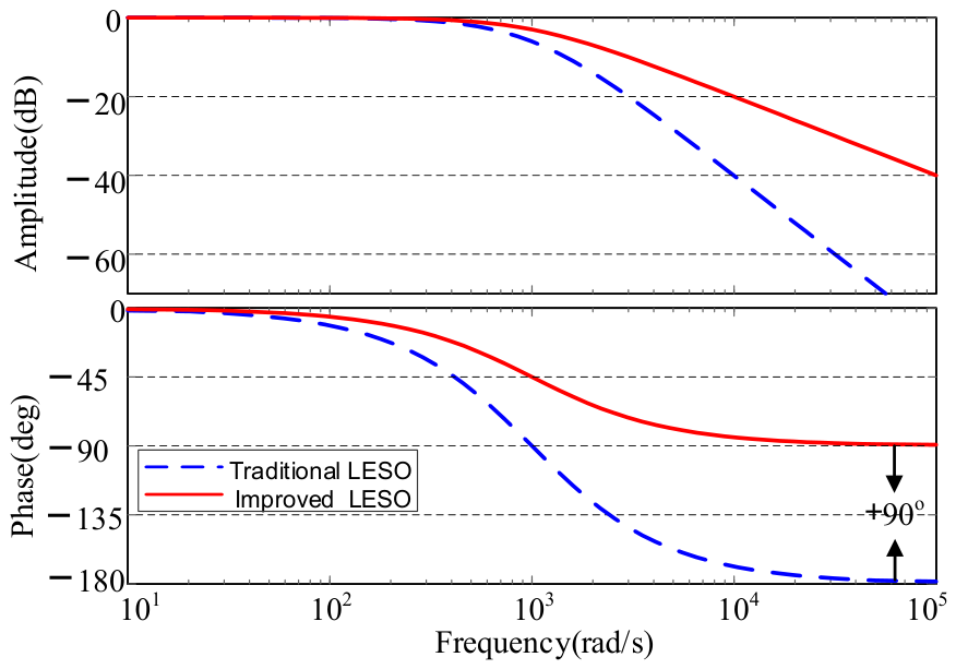
Based on the above analysis, the Bode plots of the conventional LESO and the improved LESO for total-disturbance estimation under the same bandwidth, ω 0 = 1000 rad/s, are shown in Figure 6.
It can be seen that both observers exhibit the typical characteristics of a second-order low-pass filter. Compared with the conventional LESO, the improved LESO provides a higher magnitude gain in the medium- and high-frequency ranges, while its phase advances by approximately 90°. This indicates that the improved observer not only enhances the estimation capability for high-frequency disturbances, but also effectively reduces dynamic response delay. Furthermore, for the analysis of double-frequency AC distortion under unbalanced faults, the improved LESO exhibits a magnitude gain of 0 dB and a phase delay of only 17.4°. This indicates that the improved LESO provides a higher disturbance observation gain and a smaller phase lag around the double-frequency region, thereby allowing more accurate estimation of the dominant double-frequency disturbance component induced by the negative-sequence voltage and enhancing the overall disturbance compensation capability of the system.
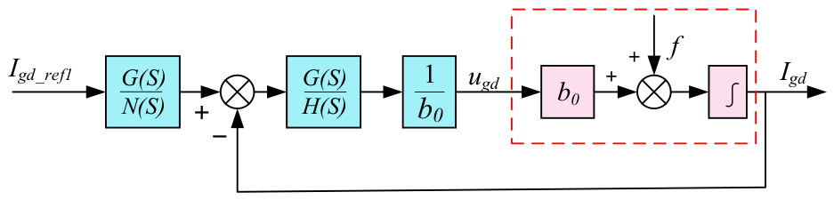
By combining Equation (11), the control block diagram of the improved LADRC model can be constructed, as shown in Figure 7.
In Figure 7, G ( s ) , N ( s ) and H ( s ) denote the transfer functions of the controller components, which satisfy:
G ( s ) = k p s 2 + k p ( β 1 + β 3 ) s + k p β 2 H ( s ) = β 3 s 2 + ( k p β 1 + k p β 3 + β 2 ) s + k p β 2 N ( s ) = s 2 + ( β 1 + k p ) s
According to Figure 7, the transfer function of the inner current-loop output of the improved LADRC with respect to the reference input I g d _ r e f ( s ) and the total disturbance F ( s ) can be derived as:
I g d _ i m p ( s ) = k p s + k p I g d _ r e f 1 ( s ) + s s + k p + ω 0 ( s + k p ) ( s + ω 0 ) 2 F ( s )
Similarly, the system output transfer function under the conventional LADRC can be obtained as:
I g d _ t r a d ( s ) = k p s + k p I g d _ r e f 2 ( s ) + s ( s + k p + 2 ω 0 ) ( s + k p ) ( s + ω 0 ) 2 F ( s )
The system output essentially consists of two components: a tracking term and a disturbance term. The tracking term depends solely on the proportional controller bandwidth k p , whereas the disturbance term mainly reflects the transient voltage shock at the instant of asymmetrical faults and the sustained double-frequency AC distortion caused by the negative-sequence component. The LADRC performance is therefore primarily determined by the influence of the disturbance term [36,37]. Accordingly, the disturbance terms in Equations (27) and (28) are analyzed in the frequency domain, as shown in Figure 8, where the control parameters are selected as ω 0 = 1000 and k p = 1000.
As can be observed from Figure 8, within the low- and medium-frequency ranges, as well as within the core ride-through frequency band, the improved LADRC exhibits significantly reduced magnitude gain and phase lag. It can effectively cover and suppress the double-frequency AC distortion induced by asymmetrical faults, demonstrating stronger disturbance rejection capability. When the frequency exceeds 1000 rad/s, its anti-disturbance performance is mainly constrained by the observer bandwidth.
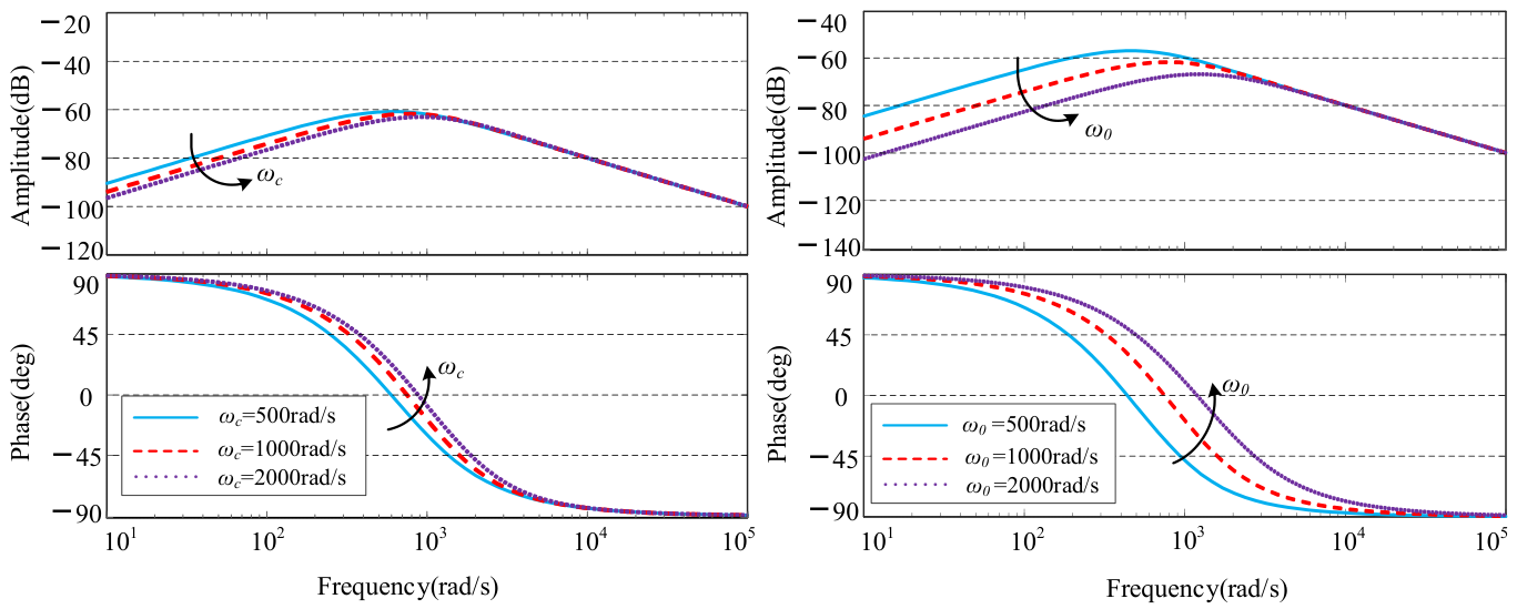
Since the input term depends only on the bandwidth of the LSEF, whereas the disturbance term is affected by both the LESO bandwidth and the LSEF bandwidth, two cases are further considered: fixing ω 0 while varying ω c , and fixing ω c while varying ω 0 . In Figure 9a, the LESO bandwidth is fixed at 1000, while the LSEF bandwidth is increased uniformly from 500 to 2000. In Figure 9b, the LSEF bandwidth is fixed at 1000, while the LESO bandwidth is increased uniformly from 500 to 2000. It is evident that, in the low-frequency range, the disturbance rejection capability and steady-state robustness of the system are enhanced as the bandwidth increases. In the medium-frequency range, the phase margin increases with bandwidth, indicating improved system stability. However, in the high-frequency range, the insensitivity to parameter variations remains similar, whereas the capability to suppress high-frequency noise decreases.
According to Equations (17) and (18), the characteristic polynomial of the improved LESO is determined by the observer parameters β 1 , β 2 and β 3 . When the conditions β 2 = ω 0 2 , β 1 + β 3 = 2 ω 0 and ω 0 > 0 are satisfied, the observer poles are located in the left half of the complex plane. Consequently, the estimation error of the total disturbance is convergent. After the lumped disturbance is estimated and compensated by the improved LESO, the grid-side current inner loop can be regarded as a closed-loop tracking system regulated by linear state error feedback. Its dominant pole is mainly determined by the feedback gain k p . When k p > 0 , the current-tracking error converges under bounded disturbances. Therefore, under the parameter conditions ω 0 > 0 and k p > 0 , the improved LADRC-based grid-side current inner loop satisfies the closed-loop stability requirement. The grid-side voltage outer loop generates the active-current reference according to the DC-link voltage deviation. This reference is constrained within an achievable range by the device current-capacity limit and the current-limiting mechanism, thereby avoiding excessive current commands during LVRT faults. Because the bandwidth of the current inner loop is higher than that of the voltage outer loop, the inner loop can track the current reference within the relatively slower time scale of the outer-loop regulation. This reduces the coupling between voltage outer-loop regulation and current inner-loop dynamics, thereby lowering the risk of oscillation in the cascaded system. The bandwidth parameters are selected according to the principle of covering the dominant fault-related disturbance frequency while considering high-frequency noise suppression. For a 50 Hz grid, the negative-sequence component under asymmetrical faults appears as a 100 Hz disturbance in the synchronous rotating dq reference frame, corresponding to an angular frequency of approximately 628 rad/s. Therefore, the LESO bandwidth should cover this frequency range to ensure sufficient observation and compensation capability for double-frequency disturbances, and the final bandwidth parameters are determined as a compromise based on the frequency-domain response and HIL experimental results. Combined with the frequency-domain responses shown in Figure 8 and Figure 9, the selected parameters reduce the disturbance gain and phase lag in the fault-related frequency range without introducing significant high-frequency noise amplification. These results support the stable operation of the grid-side closed-loop system under LVRT conditions.

5. Experimental Validation

To verify the effectiveness of the proposed coordinated fault ride-through control strategy for the FESS based on DC-link voltage deviation control and the improved LADRC, a standalone grid-connected FESS model was established on a hardware-in-the-loop (HIL) experimental platform, as shown in Figure 10. Experimental studies were carried out under two operating conditions: symmetrical and asymmetrical grid faults. Furthermore, conventional PI control, conventional LADRC, and the improved LADRC were employed to conduct a comparative analysis of the proposed LVRT scheme and the associated control strategies. The main system parameters are listed in Table 1, where the upper and lower limits of the DC-link voltage are set to 1.1 pu and 0.9 pu, respectively.
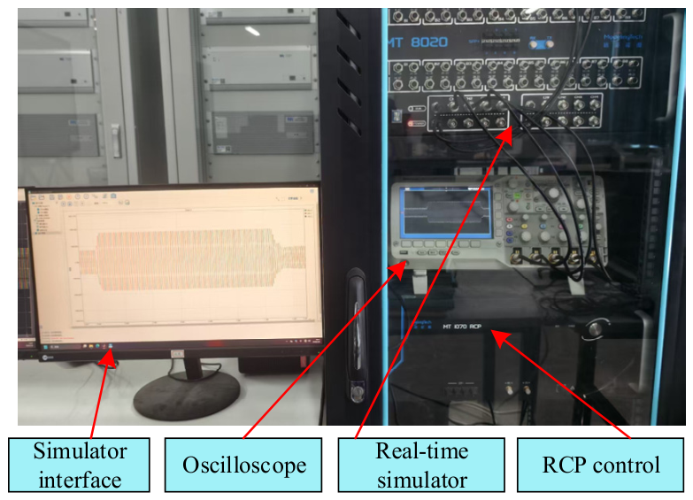
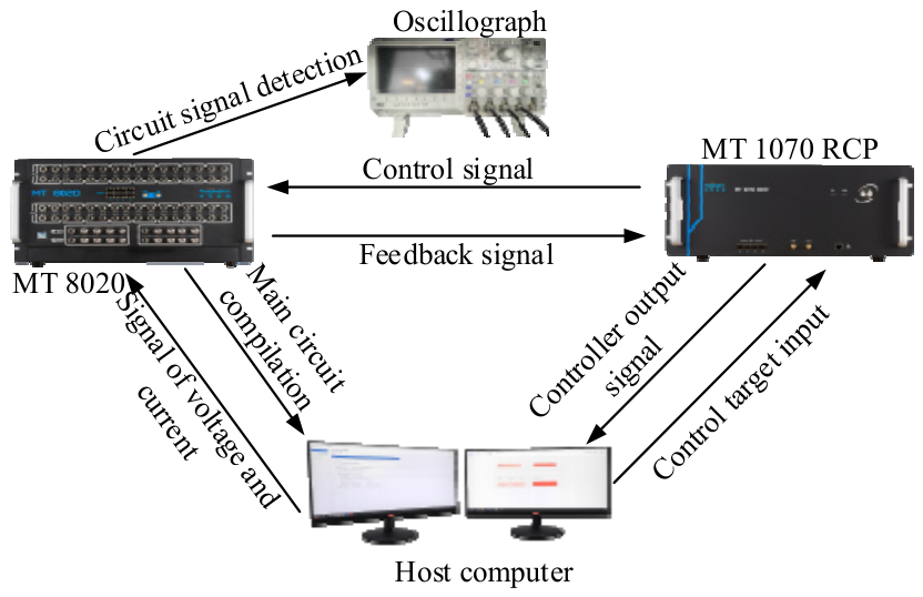
The experimental validation was conducted on a HIL platform consisting of a host computer, an MT 8020 real-time simulator (ModelingTech, Shanghai, China), an MT 1070 rapid control prototyping (RCP) controller (ModelingTech, Shanghai, China), and an oscilloscope (Tektronix, Beaverton, OR, USA), as shown in Figure 10. The overall configuration and signal flow of the HIL experimental platform are shown in Figure 11. The main power circuit of the grid-connected flywheel energy storage system was implemented on the MT 8020 real-time simulator. The main circuit model was executed in real time with a fixed simulation step of 1 μs, which enables the fast switching dynamics of the power electronic converters and the transient characteristics under grid faults to be represented. The proposed control algorithm was implemented on the MT 1070 RCP controller. The controller receives the analog signals from the real-time simulator, performs real-time computation of the control law, and generates PWM signals that are fed back to the simulator to drive the power converters, thereby forming a closed-loop HIL configuration. In the experiments, the converter switching frequency was set to 10 kHz, and the control sampling frequency was also set to 10 kHz, corresponding to a control step of 100 μs. The signal acquisition, control computation, and data transmission processes were completed within one control sampling period. The analog signals were scaled to ±10 V and processed with 16-bit resolution. An oscilloscope was used to record key experimental waveforms, including the DC-link voltage, grid-side voltage, grid-side current, and power responses. The quality of the recorded signals and the reliability of subsequent quantitative analysis depend strongly on measurement-data quality and noise characteristics [38,39]. Compared with offline simulation, the HIL platform incorporates practical factors such as sampling, computation, interface transmission, and digital control implementation under real-time closed-loop conditions. Recent studies on HIL real-time simulation also indicate that this approach is suitable for evaluating the interaction among power-electronic plant models, controller hardware, and interface processes under closed-loop operating conditions [40]. Therefore, it provides support for the real-time feasibility of the proposed LVRT control strategy and the reliability of the experimental results.
Although the improved LADRC has a more complex observer structure than conventional PI control, it does not involve online optimization, iterative calculation, or high-order matrix operations. Compared with the conventional LESO, only one proportional compensation branch is added in the disturbance-estimation feedback path, so the additional computational burden mainly consists of only a few multiplications and additions. Under the 10 kHz control sampling frequency used in the HIL experiment, the control-law calculation and PWM update can be completed within one control period. Therefore, the improved LADRC can meet the real-time implementation requirements of high-speed digital control systems.
The grid-side line-to-line voltage is set to 690 V according to the rated low-voltage AC-side voltage of the HIL experimental system and the MW-class grid-connected FESS converter. This voltage level matches the 1.0 MW power rating of the FESS and the current capacity of the grid-side converter, allowing the grid-side voltage, current, and power parameters to remain within a reasonable engineering range. Meanwhile, the 690 V line-to-line voltage is also used as a basic parameter for grid-side current reference calculation, converter capacity constraint, and current limiting during faults, and the main controller parameters are provided in Appendix A.
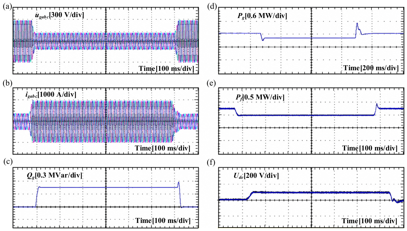
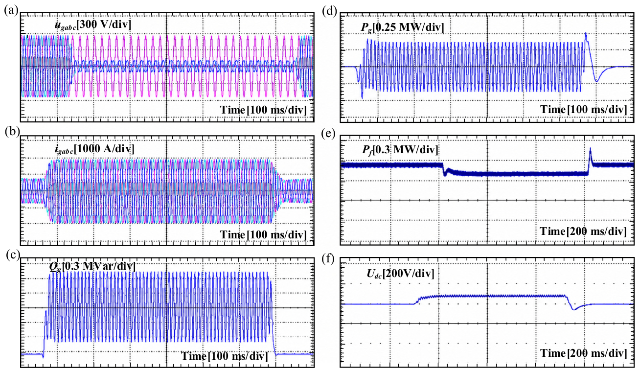
As shown in Figure 12a, the flywheel energy storage system (FESS) initially operates in the discharging mode at 650 kW. At t = 0.5 s, the grid voltage drops to 40% of its rated value and recovers to normal at t = 1.125 s after a duration of 0.625 s. It can be observed from Figure 12b that during the voltage sag, the grid-side output current amplitude increases significantly, reaching a peak of approximately 1800 A, while the three-phase currents maintain good symmetry. As shown in Figure 12c,d, the grid-side reactive power rapidly rises to about 450 kvar at t = 0.5 s. Meanwhile, due to converter capacity constraints, the grid-side active power decreases from 600 kW to 400 kW. Because the machine-side output power exceeds the power delivered by the grid-side converter at the onset of the fault, a transient active power imbalance occurs, causing the DC-link voltage to rise rapidly. When the DC-link voltage reaches the preset upper threshold, the DVCRH exits saturation and takes over the regulation of the machine-side active-current command, as shown in Figure 12e. Under its action, the machine-side power is rapidly reduced to approximately 400 kW, thereby re-establishing the power balance and stabilizing the DC-link voltage near 1650 V, as shown in Figure 12f. During the voltage sag, the proposed coordinated control strategy promptly regulates the machine-side power and maintains DC-link voltage stability, thereby ensuring continuous LVRT operation.
Figure 13 presents the experimental results for an asymmetrical grid fault where the voltages of phases A and B drop to 20% of their rated values at t = 0.5 s, with all other operating parameters remaining identical to those in the symmetrical fault experiment. As shown in Figure 13b, following the onset of the asymmetrical fault, the grid-side current increases briefly but maintains stability, with the three-phase currents reaching a steady state after approximately 25 ms. Observations from Figure 13c,d indicate that the grid-side converter responds to the LVRT command during the voltage sag, leading to a rapid rise in reactive power and a constrained reduction in active power. However, due to the influence of the negative-sequence component in the grid voltage, pronounced double-frequency pulsations are superimposed on both the active and reactive powers. As illustrated in Figure 13e, the machine-side output power decreases accordingly. Owing to the initial power imbalance, the DC-link voltage rises rapidly; once its average value reaches the preset upper safety threshold, the DVCRH exits saturation and takes over the regulation of the active-current command. Consequently, the average DC-link voltage is stabilized around 1650 V, as shown in Figure 13f.
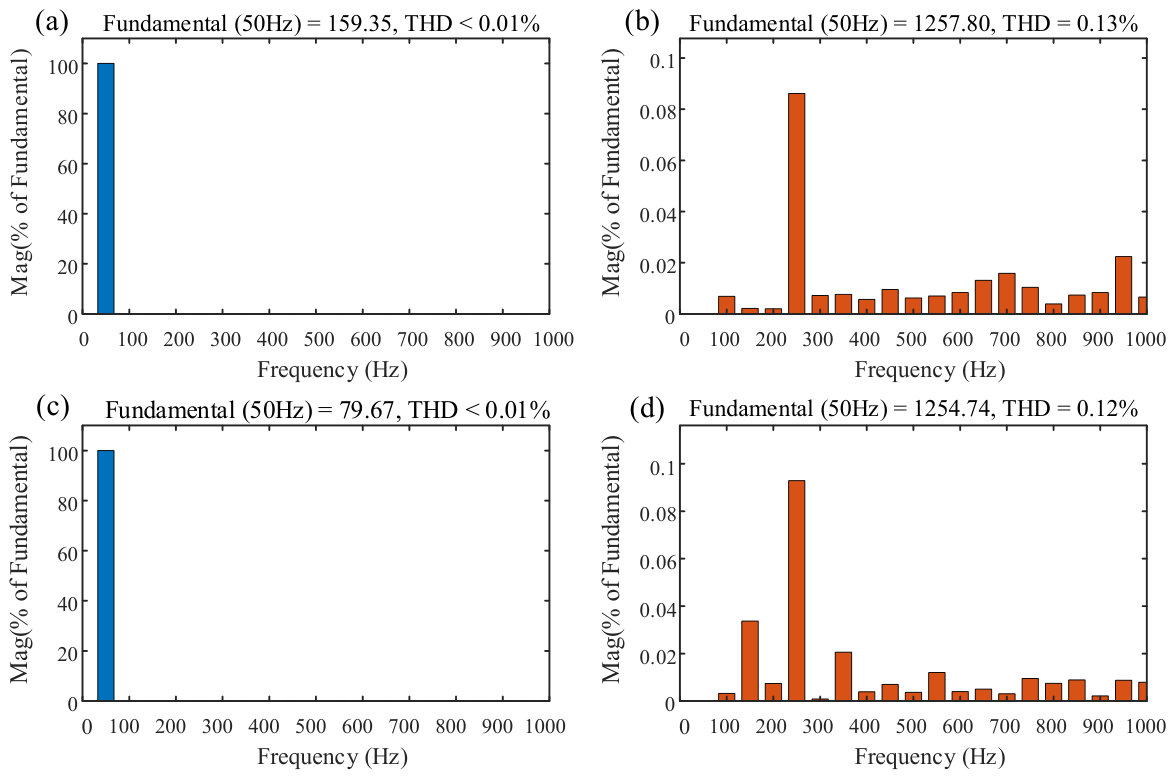
Figure 14 presents the fast Fourier transform (FFT)-based harmonic spectra of the grid-side voltage and current during the fault interval of 0.6–1.1 s. The voltage spectra are mainly concentrated at the 50 Hz fundamental component, while the high-order harmonic components are relatively small. This indicates that the voltage sag mainly changes the fundamental amplitude rather than introducing significant high-order harmonic distortion. Under both symmetrical and asymmetrical voltage sag conditions, the voltage THD values are lower than 0.01%, which is below the voltage THD limit specified in IEEE 519-2022 [41]. As shown in Figure 14b,d, the high-order harmonic components of the grid-side current remain at a low level under both symmetrical and asymmetrical voltage sag conditions, with maximum current THD values of 0.13% and 0.12%, respectively. The total demand distortion (TDD) was calculated using the rated line current of 836.74 A as the reference current, which was determined from the 1.0 MW rated power of the FESS and the 690 V grid-side line-to-line RMS voltage. Based on this reference current, the maximum current TDD values under symmetrical and asymmetrical voltage sag conditions are 0.20% and 0.18%, respectively, both of which are lower than the conservative 5% current TDD limit specified in IEEE 519-2022. These results indicate that the proposed control strategy can maintain good grid-side power quality during LVRT.
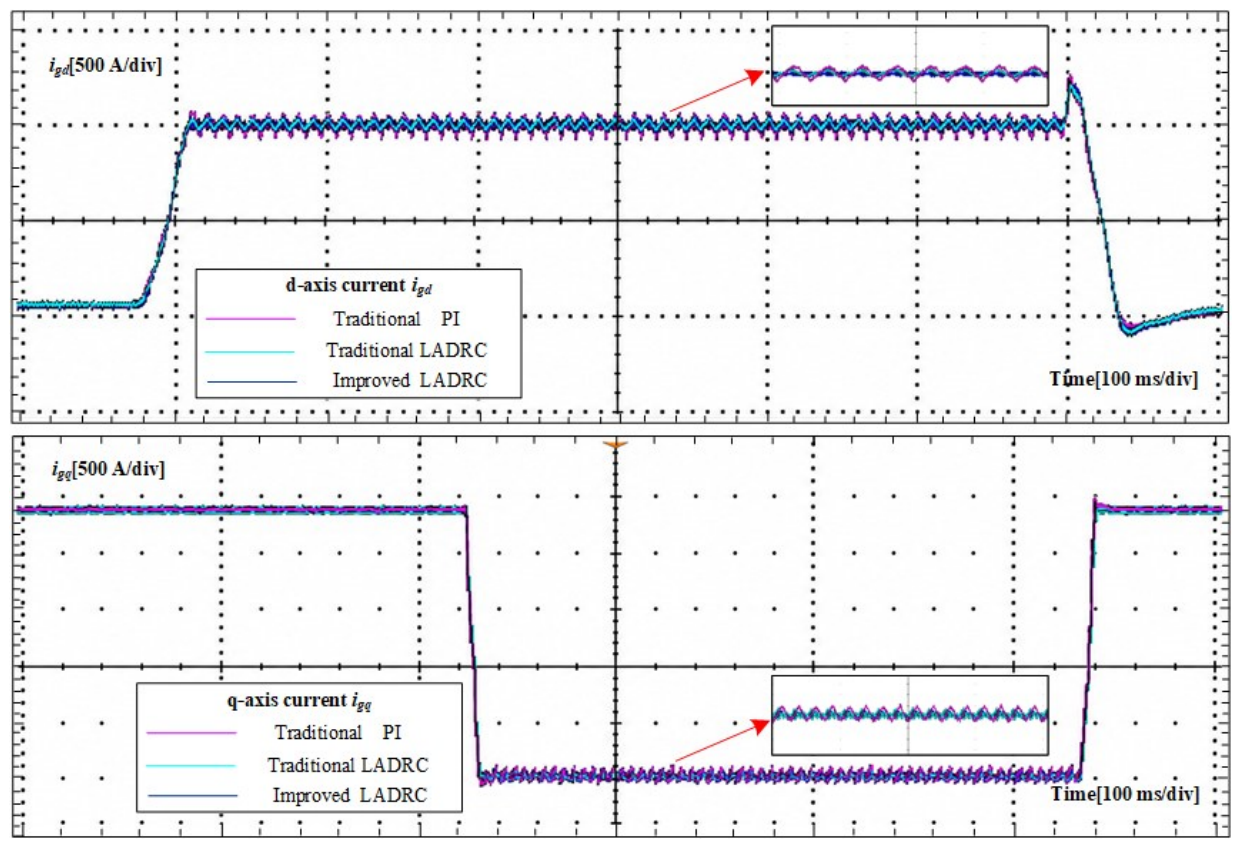
Figure 15 compares the grid-side d- and q-axis current responses under asymmetrical faults using conventional PI control, conventional LADRC, and the improved LADRC. It can be observed that, during the fault interval of 0.6–1.1 s, the peak-to-peak ripples of i g d and i g q under conventional PI control are 87.12 A and 77.00 A, respectively, while the corresponding RMS ripples are 24.18 A and 19.95 A. With conventional LADRC, the peak-to-peak ripples of i g d and i g q are reduced to 43.17 A and 41.49 A, respectively, and the RMS ripples are reduced to 10.33 A and 8.79 A, respectively. After adopting the improved LADRC, the peak-to-peak ripple and RMS ripple of i g d are further reduced to 34.35 A and 7.67 A, corresponding to reductions of 60.6% and 68.3% compared with conventional PI control, respectively. For i g q , the peak-to-peak ripple and RMS ripple under the improved LADRC are 53.22 A and 11.51 A, respectively, which are reduced by 30.9% and 42.3% compared with conventional PI control. Therefore, while maintaining a fast current-tracking response, the improved LADRC can significantly suppress the double-frequency ripple of the dq-axis currents and exhibits superior dynamic disturbance rejection capability.
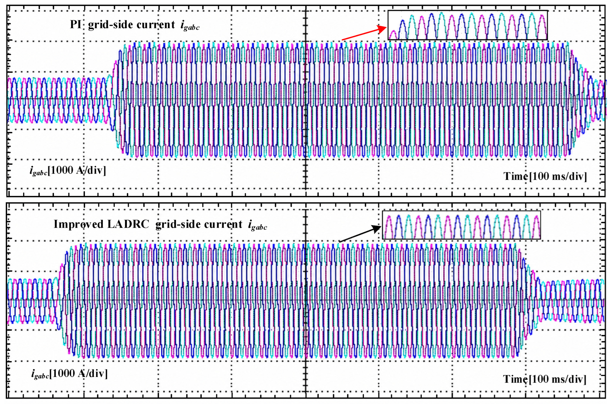
Figure 16 further compares the output waveforms of the grid-side three-phase currents under conventional PI control and the improved LADRC during the asymmetrical voltage sag. Under conventional PI control, the three-phase grid currents exhibit obvious imbalance and distortion due to the double-frequency disturbance induced by the asymmetrical fault. In particular, the amplitudes of the phase-B and phase-C currents are approximately 1815 A and 1763 A, respectively, yielding a maximum interphase peak-current deviation of about 52 A. After adopting the improved LADRC, the peak currents of phases A, B, and C are approximately 1787.9 A, 1791.7 A, and 1787.1 A, respectively, and the maximum interphase peak-current deviation is reduced to about 4.57 A, corresponding to a reduction of approximately 91.2% compared with conventional PI control. Meanwhile, the maximum RMS deviation among the three-phase currents is only 3.33 A. Therefore, the improved LADRC can effectively suppress the interphase current imbalance and current distortion caused by the asymmetrical voltage sag, allowing the three-phase currents to maintain good symmetry and sinusoidal characteristics during the fault period, thereby improving the grid-current quality of the FESS during LVRT.

6. Conclusions

This study focuses on the LVRT capability of FESS and investigates the operating mechanism and control issues under symmetrical and asymmetrical grid-voltage sag conditions. The results show that, during low-voltage faults, the reactive-power-priority support of the grid-side converter compresses its active power output capability, thereby causing an active-power imbalance between the machine side and the grid side and resulting in DC-link voltage limit violations. Under asymmetrical faults, the negative-sequence component further induces double-frequency oscillations in the grid current and power, which weaken the transient stability and degrade the grid power quality of the system. To address these issues, a coordinated fault ride-through control framework for the machine-side and grid-side converters is established. On the machine side, a coordinated regulation strategy based on cascaded limiting of the DC-link voltage deviation is adopted to achieve the adaptive reconstruction of the active-current command. On the grid side, an improved LADRC is employed to enhance the observation and compensation of double-frequency disturbances. In this way, DC-link voltage stabilization, power rebalancing between the machine side and the grid side, and grid-side disturbance rejection are achieved in a coordinated manner.
Experimental results show that the proposed coordinated control strategy exhibits strong fault adaptability and dynamic coordination capability during LVRT. Under both symmetrical and asymmetrical voltage sags, the DC-link voltage can be stabilized at approximately 1650 V, indicating that the proposed strategy can effectively re-establish the power balance between the machine side and the grid side. Under symmetrical and asymmetrical voltage sag conditions, the voltage THD values are both lower than 0.01%, while the maximum grid-current THD values are 0.13% and 0.12%, respectively, with corresponding TDD values of 0.20% and 0.18%, indicating that the harmonic distortion of the grid current is effectively suppressed. Under asymmetrical faults, the improved LADRC reduces the RMS ripples of i g d and i g q by 68.3% and 42.3%, respectively, compared with conventional PI control, and reduces the maximum interphase peak-current deviation from approximately 52 A to 4.57 A, corresponding to a reduction of about 91.2%. Therefore, the proposed strategy shows good effectiveness in DC-link voltage stabilization, double-frequency disturbance suppression, and grid-current quality improvement.
At present, the operation of practical flywheel energy storage systems is constrained by factors such as mechanical stress, motor losses, temperature conditions, and energy capacity. However, the LVRT process in the experiments of this study lasts only 0.625 s and belongs to a short-term electrical transient process. Within this time scale, the influence of these slow dynamic physical factors on the proposed high-speed coordinated electrical control is relatively limited; therefore, they are not included in the current model. Future work will establish a multi-physics comprehensive model considering mechanical constraints, loss models, thermal characteristics, and capacity limitations, so as to further evaluate the comprehensive ride-through performance of FESSs under long-duration and consecutive fault conditions.


Author Contributions

Conceptualization, D.G. and G.L.; methodology, D.G.; software, G.L.; validation, D.G., J.Z., Z.H. and G.T.; formal analysis, S.W.; investigation, G.L. and Z.H.; resources, D.G.; data curation, Y.W.; writing—original draft preparation, D.G.; writing—review and editing, J.Z.; visualization, G.T.; supervision, J.Z.; project administration, G.L.; funding acquisition, G.L. All authors have read and agreed to the published version of the manuscript.

Funding

This research was funded by the National Key R&D Program of China under the project “Hundred-Megawatt-Scale Hybrid Energy Storage Technology with Active Grid Support for Power Systems with High Renewable Energy Penetration” (Grant No. 2024YFB2408400).

Institutional Review Board Statement

Not applicable.

Informed Consent Statement

Not applicable.

Data Availability Statement

The original contributions presented in this study are included in the article. Further inquiries can be directed to the corresponding author.

Conflicts of Interest

The authors declare no conflicts of interest.

Abbreviations

The following abbreviations are used in this manuscript:
AbbreviationFull Name
FESSFlywheel energy storage system
LVRTLow-voltage ride-through
PMSMPermanent magnet synchronous machine
LADRCLinear active disturbance rejection control
LESOLinear extended state observer
LSEFLinear state error feedback
DSCDelayed signal cancelation
HILHardware-in-the-loop
RCPRapid control prototyping
FFTFast Fourier transform
THDTotal harmonic distortion
TDDTotal demand distortion
RMSRoot mean square
DVCRHHigh-voltage DC-link voltage deviation coordinator
DVCRLLow-voltage DC-link voltage deviation coordinator

Appendix A

Table A1. Main controller parameters used in the HIL experiments.
ControllerParametersValue
Machine-side current-loop PI K p , f i ,   K i , f i 1, 200
Machine-side power outer-loop PI K p , f p ,   K i , f p 0.001, 1
Grid-side current-loop PI K p , g c ,   K i , g c 2, 200
Grid-side voltage-loop PI K p , g v ,   K i , g v 4, 120
DVCRH/DVCRL PI coordinators K p , H ,   K i , H ,
K p , L ,   K i , L
10, 200,
10, 200
Improved LADRC ω 0 , K ,   b 0 1000, 1000, 500

References

  1. Lim, S.; Kim, T.; Lee, K.Y.; Choi, D.; Park, J.W. Impact of high penetration of renewables on power system frequency response: A review and verification. Renew. Sustain. Energy Rev. 2025, 217, 115728. [Google Scholar] [CrossRef]
  2. Li, X.; Palazzolo, A. A review of flywheel energy storage systems: State of the art and opportunities. J. Energy Storage 2022, 46, 103576. [Google Scholar] [CrossRef]
  3. Ji, W.; Hong, F.; Zhao, Y.; Liang, L.; Du, H.; Hao, J.; Fang, F.; Liu, J. Applications of flywheel energy storage system on load frequency regulation combined with various power generations: A review. Renew. Energy 2024, 223, 119975. [Google Scholar] [CrossRef]
  4. Akram, U.; Nadarajah, M.; Shah, R.; Milano, F. A review on rapid responsive energy storage technologies for frequency regulation in modern power systems. Renew. Sustain. Energy Rev. 2020, 120, 109626. [Google Scholar] [CrossRef]
  5. Matos, C.; Rosales-Asensio, E.; Carta, J.A.; Cabrera, P. Flywheels in renewable energy systems: An analysis of their role in managing intermittency. J. Energy Storage 2025, 122, 116674. [Google Scholar] [CrossRef]
  6. Qin, B.; Li, H.; Zhou, X.; Li, J.; Liu, W. Low-voltage ride-through techniques in DFIG-based wind turbines: A review. Appl. Sci. 2020, 10, 2154. [Google Scholar] [CrossRef]
  7. Rincon, D.J.; Mantilla, M.A.; Rey, J.M.; Garnica, M.; Guilbert, D. An overview of flexible current control strategies applied to LVRT capability for grid-connected inverters. Energies 2023, 16, 1052. [Google Scholar] [CrossRef]
  8. Wang, J.; Ben, Y.; Zhang, J.; Feng, H. Low voltage ride-through control strategy for a wind turbine with permanent magnet synchronous generator based on operating simultaneously of rotor energy storage and a discharging resistance. Energy Rep. 2022, 8, 5861–5870. [Google Scholar] [CrossRef]
  9. Li, C.; Cao, Y.; Li, B.; Liu, B.; Qiao, F.; Chen, P. A novel low voltage ride-through scheme for DFIG based on the cooperation of hybrid energy storage system and crowbar circuit. J. Energy Storage 2023, 73, 108879. [Google Scholar] [CrossRef]
  10. Yang, Z.; Gao, B.; Cao, Z. Low-voltage ride-through strategy for offshore wind turbines based on current relaxation region. Electr. Power Syst. Res. 2023, 223, 109704. [Google Scholar] [CrossRef]
  11. Hassan, Z.; Amir, A.; Selvaraj, J.; Rahim, N.A. A review on current injection techniques for low-voltage ride-through and grid fault conditions in grid-connected photovoltaic system. Sol. Energy 2020, 207, 851–873. [Google Scholar] [CrossRef]
  12. Bo, L.; Wang, J.; Zhang, X.; Su, Y.; Cheng, X.; Zhang, Z.; Ma, S.; Wang, J.; Fang, X. Research on the data-driven identification of control parameters for voltage ride-through in energy storage systems. Appl. Sci. 2025, 15, 8249. [Google Scholar] [CrossRef]
  13. Espinosa Domínguez, J.; Serban, I.; Torres Breffe, O.E. Adaptive voltage fault ride-through control of a battery energy storage system according to the Cuban grid code. Energy 360 2025, 4, 100033. [Google Scholar] [CrossRef]
  14. De Carne, G.; Maroufi, S.M.; Beiranvand, H.; De Angelis, V.; D’Arco, S.; Gevorgian, V.; Waczowicz, S.; Mather, B.; Liserre, M.; Hagenmeyer, V. The role of energy storage systems for a secure energy supply: A comprehensive review of system needs and technology solutions. Electr. Power Syst. Res. 2024, 236, 110963. [Google Scholar] [CrossRef]
  15. Daoud, M.I.; Massoud, A.M.; Abdel-Khalik, A.S.; Elserougi, A.; Ahmed, S. A flywheel energy storage system for fault ride through support of grid-connected VSC HVDC-based offshore wind farms. IEEE Trans. Power Syst. 2016, 31, 1671–1680. [Google Scholar] [CrossRef]
  16. Hasanien, H.M.; Tostado-Véliz, M.; Turky, R.A.; Jurado, F. Hybrid adaptive controlled flywheel energy storage units for transient stability improvement of wind farms. J. Energy Storage 2022, 54, 105262. [Google Scholar] [CrossRef]
  17. Hossain, M.I.; Hamanah, W.M.; Alam, M.S.; Shafiullah, M.; Abido, M.A. Fault ride through and intermittency improvement of renewable energy integrated MMC-HVDC system employing flywheel energy storage. IEEE Access 2023, 11, 50528–50546. [Google Scholar] [CrossRef]
  18. Zhai, D.; Yao, L.; Liao, S.; Xu, J.; Mao, B.; Xie, B. Modeling and control of flywheel energy storage system. In Proceedings of the 2023 6th International Conference on Electronics Technology (ICET), Chengdu, China, 12–15 May 2023; pp. 1289–1293. [Google Scholar] [CrossRef]
  19. Zheng, X.; Wu, Z.; Song, G.; Zhang, J.; Yang, P.; Zhang, Z.; Lu, X. Low-voltage ride-through control strategy for flywheel energy storage system. Energy Sci. Eng. 2024, 12, 1486–1502. [Google Scholar] [CrossRef]
  20. Sturm, G.; Hofmann, W.; Kienast, J. Low voltage ride through of a flywheel energy storage system with doubly fed induction machine and modular multilevel matrix converter. Electr. Eng. 2025, 107, 10661–10677. [Google Scholar] [CrossRef]
  21. Xu, K.; Guo, Y.; Lei, G.; Zhu, J. A review of flywheel energy storage system technologies. Energies 2023, 16, 6462. [Google Scholar] [CrossRef]
  22. Wu, F.; Sun, Z.; Xu, W.; Li, Z.; Lyu, J. A control parameters design method with multi-constrains for an LCL-filtered grid-connected inverter in a weak grid. Front. Energy Res. 2022, 10, 798793. [Google Scholar] [CrossRef]
  23. Yang, L.; Zhao, Q. Hardware-in-the-loop simulation of flywheel energy storage systems for power control in wind farms. Electronics 2024, 13, 3610. [Google Scholar] [CrossRef]
  24. Jia, Y.; Wu, Z.; Zhang, J.; Yang, P.; Zhang, Z. Control strategy of flywheel energy storage system based on primary frequency modulation of wind power. Energies 2022, 15, 1850. [Google Scholar] [CrossRef]
  25. Khan, D.; Zhu, K.; Hu, P.; Waseem, M.; Ahmed, E.M.; Lin, Z. Active damping of LCL-filtered grid-connected inverter based on parallel feedforward compensation strategy. Ain Shams Eng. J. 2023, 14, 101902. [Google Scholar] [CrossRef]
  26. Nguyen Huy, T.; Le Hanh, D.; Takano, H.; Nguyen Duc, T. Cooperative LVRT control for protecting PMSG-based WTGs using battery energy storage system. Energy Rep. 2023, 9, 590–598. [Google Scholar] [CrossRef]
  27. Yadav, M.; Pal, N.; Saini, D.K. Low voltage ride through capability for resilient electrical distribution system integrated with renewable energy resources. Energy Rep. 2023, 9, 833–858. [Google Scholar] [CrossRef]
  28. Berger, M.; Kocar, I.; Farantatos, E.; Haddadi, A. Dual control strategy for grid-tied battery energy storage systems to comply with emerging grid codes and fault ride through requirements. J. Mod. Power Syst. Clean Energy 2022, 10, 977–988. [Google Scholar] [CrossRef]
  29. Mei, H.; Jia, C.; Fu, J.; Luan, X. Low voltage ride through control strategy for MMC photovoltaic system based on model predictive control. Int. J. Electr. Power Energy Syst. 2021, 125, 106530. [Google Scholar] [CrossRef]
  30. Fang, H.; Zhang, X.; Wei, Y. Supercapacitor energy storage system based coordinative low-voltage-ride-through control for wind energy conversion system. In Proceedings of the 2021 24th International Conference on Electrical Machines and Systems (ICEMS), Gyeongju, Republic of Korea, 31 October–3 November 2021; pp. 276–280. [Google Scholar] [CrossRef]
  31. Zeb, K.; Islam, S.U.; Khan, I.; Uddin, W.; Ishfaq, M.; Busarello, T.D.C.; Muyeen, S.M.; Ahmad, I.; Kim, H.J. Faults and fault ride through strategies for grid-connected photovoltaic system: A comprehensive review. Renew. Sustain. Energy Rev. 2022, 158, 112125. [Google Scholar] [CrossRef]
  32. Rachi, M.R.K.; Awal, M.A.; Husain, I. Asymmetrical fault ride-through and power oscillation characterization for grid-tied voltage source converters. IEEE Trans. Ind. Appl. 2023, 59, 4550–4561. [Google Scholar] [CrossRef]
  33. Zhou, X.; Liu, Q.; Ma, Y.; Xie, B. DC-link voltage research of photovoltaic grid-connected inverter using improved active disturbance rejection control. IEEE Access 2021, 9, 9884–9894. [Google Scholar] [CrossRef]
  34. Su, Z.; Sun, L.; Xue, W.; Lee, K.Y. A review on active disturbance rejection control of power generation systems: Fundamentals, tunings and practices. Control Eng. Pract. 2023, 141, 105716. [Google Scholar] [CrossRef]
  35. Ahmed, H.; Ushirobira, R.; Efimov, D. Arbitrarily fast delayed signal cancellation PLL for grid-integration of renewable energy sources. IET Renew. Power Gener. 2025, 19, e12657. [Google Scholar] [CrossRef]
  36. He, G.; Chen, G.; Dong, Y.; Li, G.; Zhang, W. Research on LADRC of Grid-Connected Inverter Based on LCCL. Energies 2022, 15, 4686. [Google Scholar] [CrossRef]
  37. Feng, Z.; Zhou, X.; Wang, C.; Huang, W.; Chen, Z. LADRC-Based Grid-Connected Control Strategy for Single-Phase LCL-Type Inverters. PLoS ONE 2024, 19, e0303591. [Google Scholar] [CrossRef]
  38. Babak, V.; Zaporozhets, A.; Kuts, Y.; Fryz, M.; Scherbak, L. Examples of Stochastic Noise Signals Identification. In Noise Signals: Modelling and Analyses; Springer: Cham, Switzerland, 2024; pp. 171–196. [Google Scholar] [CrossRef]
  39. Babak, V.; Babak, S.; Eremenko, V.; Kuts, Y.; Zaporozhets, A. Quantitative Evaluations of Measurement Information. In Information-Measuring Systems: Theory and Application; Springer: Cham, Switzerland, 2025; pp. 25–61. [Google Scholar] [CrossRef]
  40. Lauss, G.; Strunz, K. Accurate and stable Hardware-in-the-Loop (HIL) real-time simulation of integrated power electronics and power systems. IEEE Trans. Power Electron. 2021, 36, 10920–10932. [Google Scholar] [CrossRef]
  41. IEEE Std 519-2022; IEEE Standard for Harmonic Control in Electric Power Systems. IEEE: New York, NY, USA, 2022. [CrossRef]
Figure 1. Grid-connected topology and steady-state control of FESS.
Applsci 16 05388 g001
Figure 2. Conventional machine-side control scheme during grid-voltage faults.
Applsci 16 05388 g002
Figure 3. Conventional grid-side control scheme during grid-voltage faults.
Applsci 16 05388 g003
Figure 4. Machine-side coordinated control based on DC voltage deviation.
Applsci 16 05388 g004
Figure 5. Improved LESO structure.
Applsci 16 05388 g005
Figure 6. Bode plot of the disturbance estimation capability of the two LESOs.
Applsci 16 05388 g006
Figure 7. Control block diagram of the improved LADRC model.
Applsci 16 05388 g007
Figure 8. Bode plots of the disturbance term under different LADRC schemes.
Applsci 16 05388 g008
Figure 9. Bode plots of the frequency-domain characteristics of the disturbance term of the improved LADRC: (a) fixed ω 0 with increasing ω c ; (b) fixed ω c with increasing ω 0 .
Applsci 16 05388 g009
Figure 10. HIL experimental platform.
Applsci 16 05388 g010
Figure 11. Block diagram of the HIL experimental platform.
Applsci 16 05388 g011
Figure 12. LVRT experimental results under symmetrical voltage sag. (a) grid-side three-phase voltage; (b) grid-side three-phase current; (c) grid-side reactive power; (d) grid-side active power; (e) flywheel-side active power; (f) DC-link voltage.
Applsci 16 05388 g012
Figure 13. LVRT experimental results under asymmetrical voltage sag. (a) grid-side three-phase voltage; (b) grid-side three-phase current; (c) grid-side reactive power; (d) grid-side active power; (e) flywheel-side active power; (f) DC-link voltage.
Applsci 16 05388 g013
Figure 14. FFT-based harmonic spectra of grid voltage and grid current during the fault interval. (a) grid-voltage harmonic spectrum under symmetrical voltage sag; (b) grid-current harmonic spectrum under symmetrical voltage sag; (c) grid-voltage harmonic spectrum under asymmetrical voltage sag; (d) grid-current harmonic spectrum under asymmetrical voltage sag.
Applsci 16 05388 g014
Figure 15. Comparison of three control strategies for dq-axis currents under asymmetrical faults.
Applsci 16 05388 g015
Figure 16. Comparison of grid-side three-phase currents under conventional PI control and improved LADRC during asymmetrical faults.
Applsci 16 05388 g016
Table 1. Main System Parameters.
Main ParameterValue
Rated Power of Flywheel P f (MW)1.0
Rated DC-link Voltage U d c (V)1500
Stator Resistance of Flywheel Motor R (Ω)0.006
Number of Pole Pairs P n 4
Inductance L d (mH)3.95
Inductance L q (mH)3.95
Grid line voltage RMS U g (V)690
Grid normal frequency f g (Hz)50
Inverter side filter inductor L 1 (mH)0.8
Grid side filter inductor L 2 (mH)0.1
Filter capacitor C ( μ F )50
Disclaimer/Publisher’s Note: The statements, opinions and data contained in all publications are solely those of the individual author(s) and contributor(s) and not of MDPI and/or the editor(s). MDPI and/or the editor(s) disclaim responsibility for any injury to people or property resulting from any ideas, methods, instructions or products referred to in the content.