1. Introduction
Amid the continuous progress in China’s shipping industry and the management of rivers, lakes, and seas, dredging projects generate a substantial amount of dredged soil annually [
1,
2,
3,
4,
5]. Dredged soil typically exhibits elevated moisture levels and a substantial proportion of clay particles, rendering it unsuitable for direct application in earthwork projects due to its inadequate strength and pronounced deformability, which pose risks to structural stability [
6,
7]. The use of traditional curing agents like cement and lime in low dosages to treat poor engineering soils such as dredged soil (referred to as “semi-cured improved soil” in this study), combined with compaction, can make it suitable for use as subgrade filling material [
8,
9]. As an alternative to conventional binders, a novel curing agent designated as CGF—composed of calcium carbide slag, blast furnace slag, and fly ash—has been developed from industrial by-products. This material can be effectively employed in the semi-curing treatment of soft soils [
10,
11]. However, in seasonally frozen regions, subgrade filling materials often experience strength degradation due to freeze–thaw cycles, which can affect the long-term stability of the subgrade [
12,
13]. Therefore, investigating the mechanical properties and micro-mechanisms of CGF semi-cured improved soil under freeze–thaw cycles holds significant scientific importance for promoting the safe and efficient utilization of multi-source industrial solid waste and dredged soil in subgrade engineering.
Previous studies have demonstrated that the addition of cement or lime markedly enhances the physical and mechanical behavior of problematic soils, including dredged materials [
14,
15,
16,
17]. In terms of the improvement mechanism, the reaction mechanism of semi-curing improvement is essentially consistent with that of solidification. The semi-curing improvement with cement is primarily achieved through hydration reactions and ion exchange reactions, while the semi-curing improvement with lime is mainly accomplished through flocculation and agglomeration reactions [
18,
19]. Unlike solidification, semi-curing improvement is often accompanied by compaction. After the application of compaction energy, the semi-cured improved soil gradually becomes denser, leading to an increase in strength.
In research on the freeze–thaw cycle resistance characteristics of semi-cured improved soil, scholars have conducted freeze–thaw cycle tests to investigate changes in the macro- and micro-properties of semi-cured improved soil under the influence of freeze–thaw cycles. After undergoing freeze–thaw cycles, the mass of semi-cured improved soil shows a decreasing trend, with the mass loss primarily concentrated in the first five freeze–thaw cycles [
20]. The unconfined compressive strength and resilience modulus of semi-cured improved soil gradually decrease with an increase in the number of freeze–thaw cycles [
21,
22,
23,
24]. Regarding the microstructure of semi-cured improved soil under freeze–thaw cycles, nuclear magnetic resonance and computed tomography tests have confirmed that freeze–thaw cycles alter the micro-pore structure of semi-cured improved soil. As the number of freeze–thaw cycles increases, small pores (10–100 nm) and voids continuously develop and connect, leading to a reduction in their proportion, while the proportions of mesopores (100–1000 nm) and macropores (>1000 nm) gradually increase [
25,
26].
This study utilizes compaction tests to investigate the variation in compaction characteristics of CGF semi-cured improved dredged soil with different curing agent contents. For semi-cured improved dredged soil samples prepared at optimal moisture content, freeze–thaw cycle tests, unconfined compressive strength tests, X-ray diffraction (XRD), scanning electron microscopy (SEM), and mercury intrusion porosimetry (MIP) tests are conducted. The aim is to examine the macroscopic properties of semi-cured improved dredged soil under freeze–thaw cycles and their intrinsic relationship with microscopic characteristics.
2. Materials and Methods
2.1. Materials
2.1.1. Test Soil
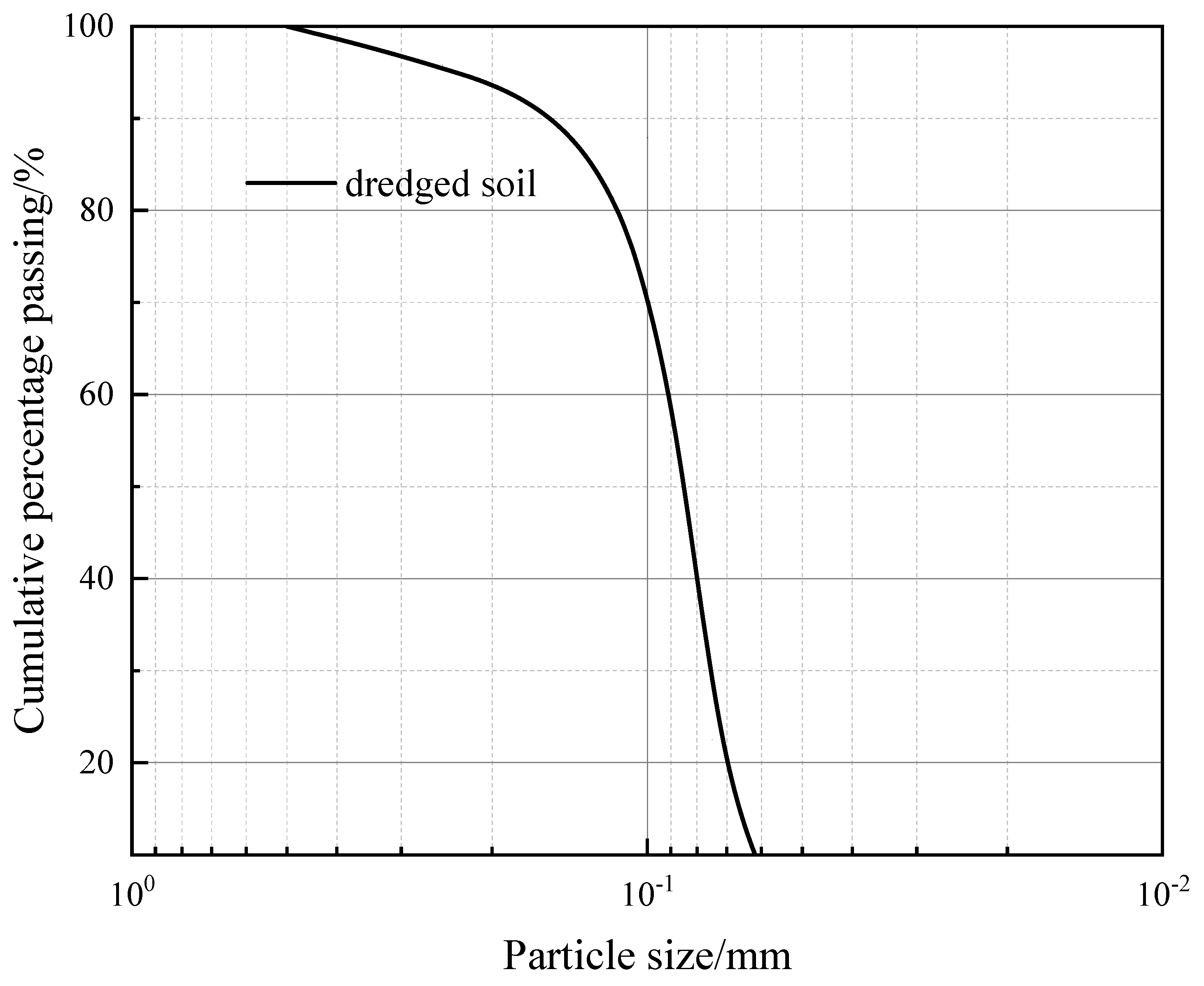
The dredged soil used in the test was sourced from the West Operation Area of Weifang Port in Weifang City, Shandong Province. The soil sample was yellowish-brown and contained a small amount of plant debris. The sample was dried, crushed, and ground, had impurities removed, and was passed through a 0.5 mm sieve. Basic physical property tests were conducted on the soil sample in accordance with the “Standard for Geotechnical Testing Methods” (GB/T 50123—2019) [
27]. The cumulative particle size distribution curve of the soil sample is shown in
Figure 1. The uniformity coefficient of the soil sample is 5.29, and the curvature coefficient is 4.18, indicating poorly graded soil with poor engineering properties. According to the “Code for Design of Building Foundations” (GB 50007-2011) [
28], the dredged soil from Weifang Port is classified as silty sand.
2.1.2. Curing Agent
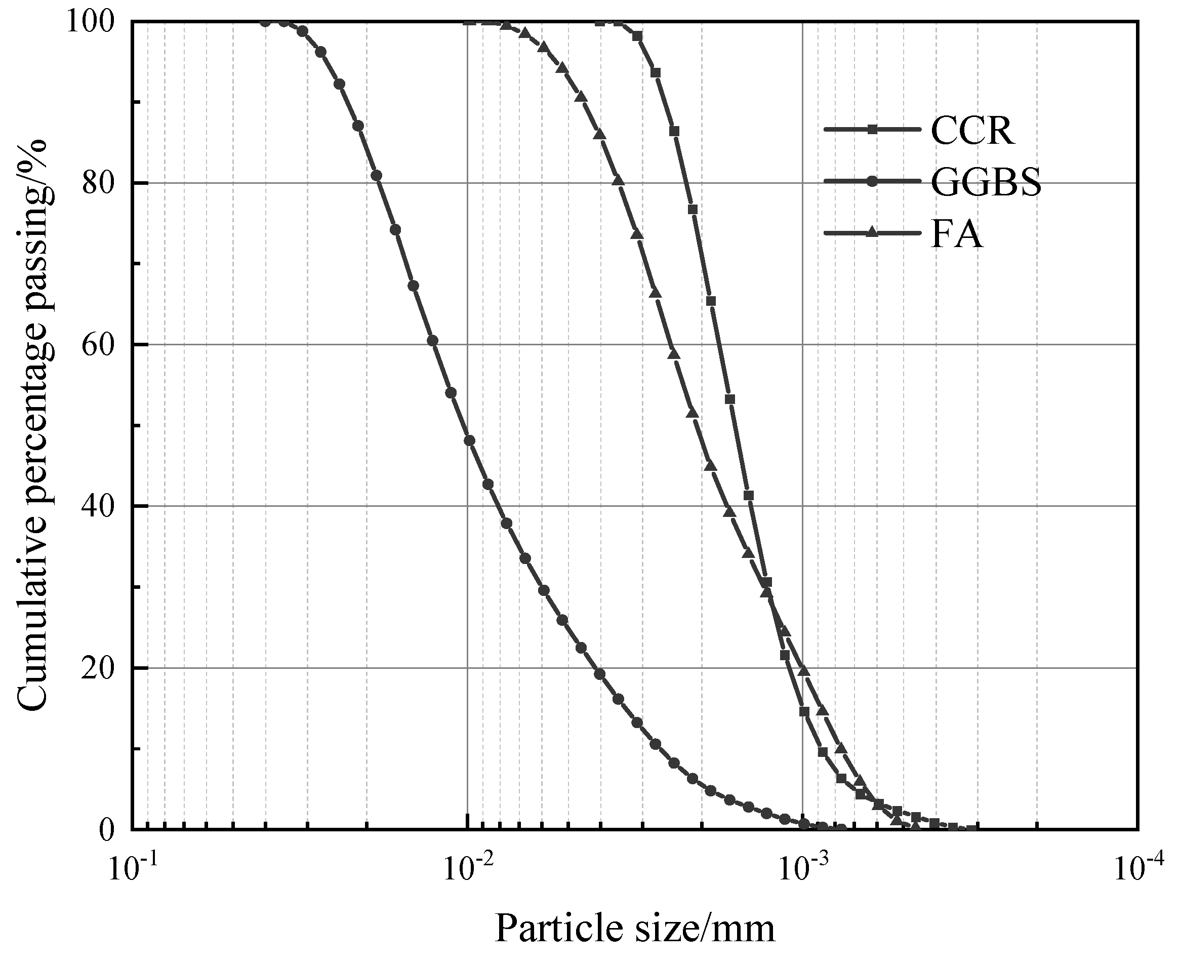
The CGF curing agent used in the test was independently developed by the research group and was prepared by mixing calcium carbide residue (CCR), ground granulated blast furnace slag (GGBS), and fly ash (FA) in a mass ratio of 4:4:2. CCR was sourced from an acetylene production plant in Huangdao, Qingdao City, Shandong Province, with a pH value of 13.5, providing an alkaline environment and serving as the alkali activator in the CGF curing agent. GGBS was obtained from a steel plant in Jinan, Shandong Province, and is a pozzolanic material with high reactivity. FA was sourced from a power plant in Qingdao, Shandong Province, and is classified as Class I fly ash. The cumulative particle size distribution curves of the components of the CGF curing agent are presented in
Figure 2. The chemical compositions of each component of the CGF solidifying agent are shown in
Table 1.
2.2. Preparation of Freeze–Thaw Cycle Test Samples
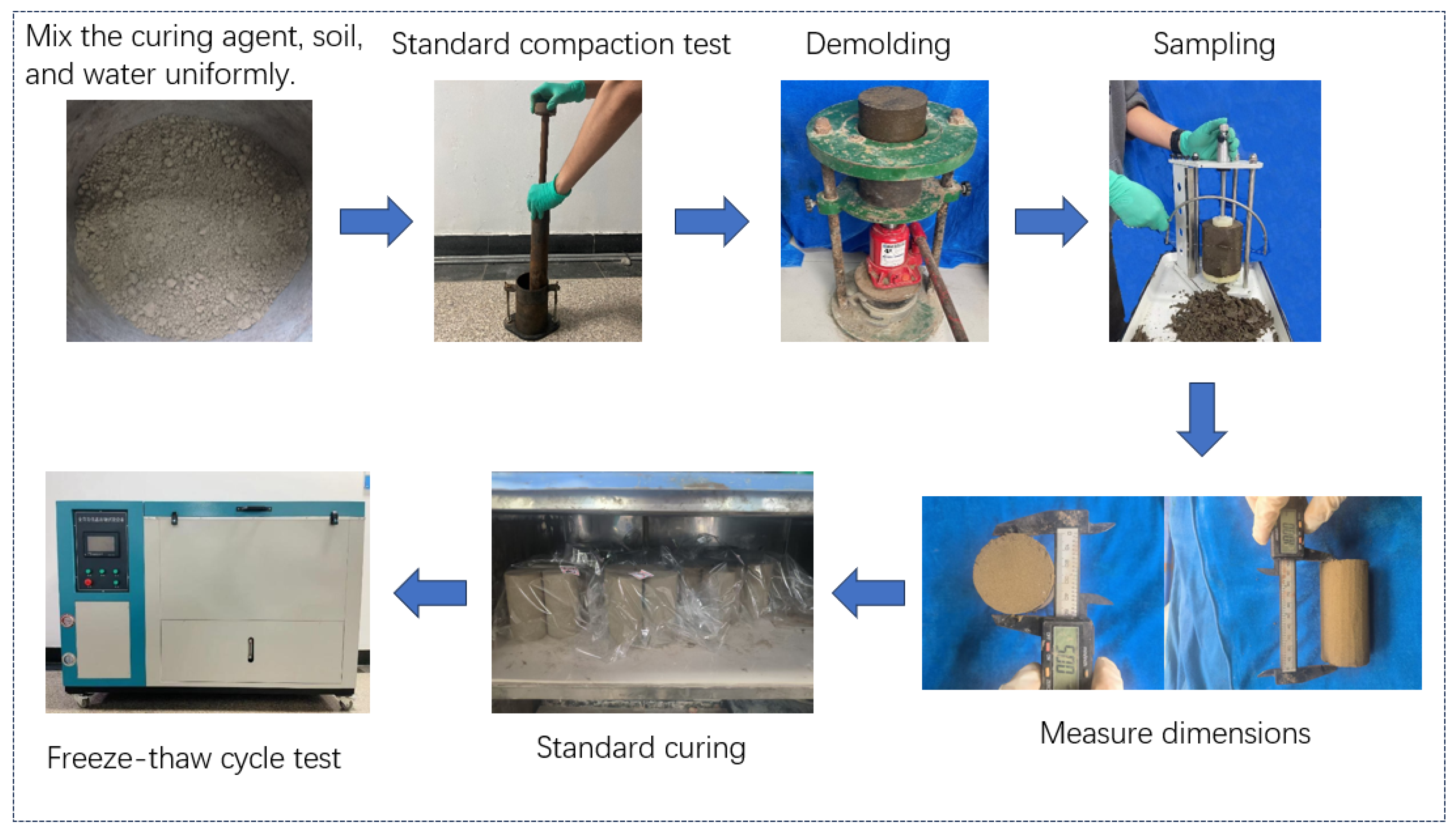
Based on the results of the compaction test, samples for the freeze–thaw cycle test were prepared at the optimal moisture content. The test soil, curing agent, and water were homogeneously blended before being compacted into molds. Following compaction, the specimens were extracted from the molds and trimmed with a soil knife to achieve cylindrical dimensions of 50 mm in diameter and 100 mm in height. These specimens were then placed in a standard curing chamber for curing (temperature: 20 ± 2 °C, humidity: ≥95%) for 28 days. The specific sample preparation plan is shown in
Table 2, and the sample preparation process is illustrated in
Figure 3.
2.3. Methods
2.3.1. Compaction Test
A compaction test was conducted by mixing the test soil, curing agent, and water in a certain proportion and stirring them uniformly. The test instrument used was a light manual compactor (
Figure 3). First, a thin layer of Vaseline was applied to the inner wall of the compaction mold, and the mold was weighed. The test was carried out in three layers, with each layer compacted 25 times. The surface between layers was scored to prevent separation. After compaction, the soil sample was leveled and weighed. Subsequently, the compacted soil sample was demolded, and finally, the central part of the compacted soil sample was taken to determine its moisture content.
2.3.2. Freeze–Thaw Cycle Test
Freeze–thaw cycle tests were performed on specimens that had undergone 28 days of standard curing. A fully automatic freeze–thaw testing apparatus was used throughout the experiment. The temperature regime was set to alternate between −20 °C and +20 °C. Each complete freeze–thaw cycle consisted of a 24 h freezing phase at −20 °C, followed immediately by a 23 h thawing phase at +20 °C, after which the temperature was reduced back to −20 °C to initiate the subsequent cycle. This procedure is consistent with the general principles outlined in ASTM D560-03. Specimens were subjected to 0, 2, 4, 6, 8, and 10 freeze–thaw cycles. After completing each designated number of cycles, the specimens were removed from the apparatus for mass measurement and unconfined compressive strength testing.
2.3.3. Unconfined Compressive Strength Test
The unconfined compressive strength test was conducted on specimens that had undergone the specified number of freeze–thaw cycles. The unconfined compressive strength testing apparatus used was the WCY-1 model, with a loading rate of 1 mm/min. The stress–strain curve of the specimen was obtained, and the peak stress was taken as the unconfined compressive strength of the semi-cured improved dredged soil.
2.3.4. Microscopic Test
(1) XRD test
The XRD test was conducted using an X’Pert Powder X-ray diffractometer (manufactured by Malvern Panalytical, Almelo, Netherlands). The test range was set to 5–75°, with a scanning speed of 5°/min. The scanning method employed a 2θ goniometer. The anode target material was Cu, and the X-ray generator operated at a tube voltage of 40 kV and a tube current of 40 mA. After the unconfined compressive strength test, fresh fractured surfaces were collected, ground, and passed through a 0.075 mm sieve. The mineral phases of the samples were then tested.
(2) SEM test
For the SEM test, the microstructure of the CGF semi-solidified improved dredged soil was investigated using a Zeiss GeminiSEM 300 field emission scanning electron microscope (manufactured by Carl Zeiss AG, Oberkochen, Germany). The magnifications employed in this study were 5000×, 10,000×, and 20,000×.
(3) MIP test
The MIP test was conducted using a MicroActive AutoPore V9600 mercury intrusion porosimeter (manufactured by Micromeritics Instrument Corporation, Norcross, GA, USA). The surface tension of mercury was 0.48 N/m, the contact angle was 140°, and the maximum pressure applied was 265 MPa.
Statement on Generative Artificial Intelligence: The authors declare that no generative artificial intelligence (GenAI) tools were used in the writing of this manuscript, including the generation of text, data, graphics, or any other content. All analyses, interpretations, and conclusions are the sole work of the authors.
3. Performance of CGF Semi-Solidified Improved Soil Under Freeze–Thaw Cycles
3.1. Compaction Characteristics
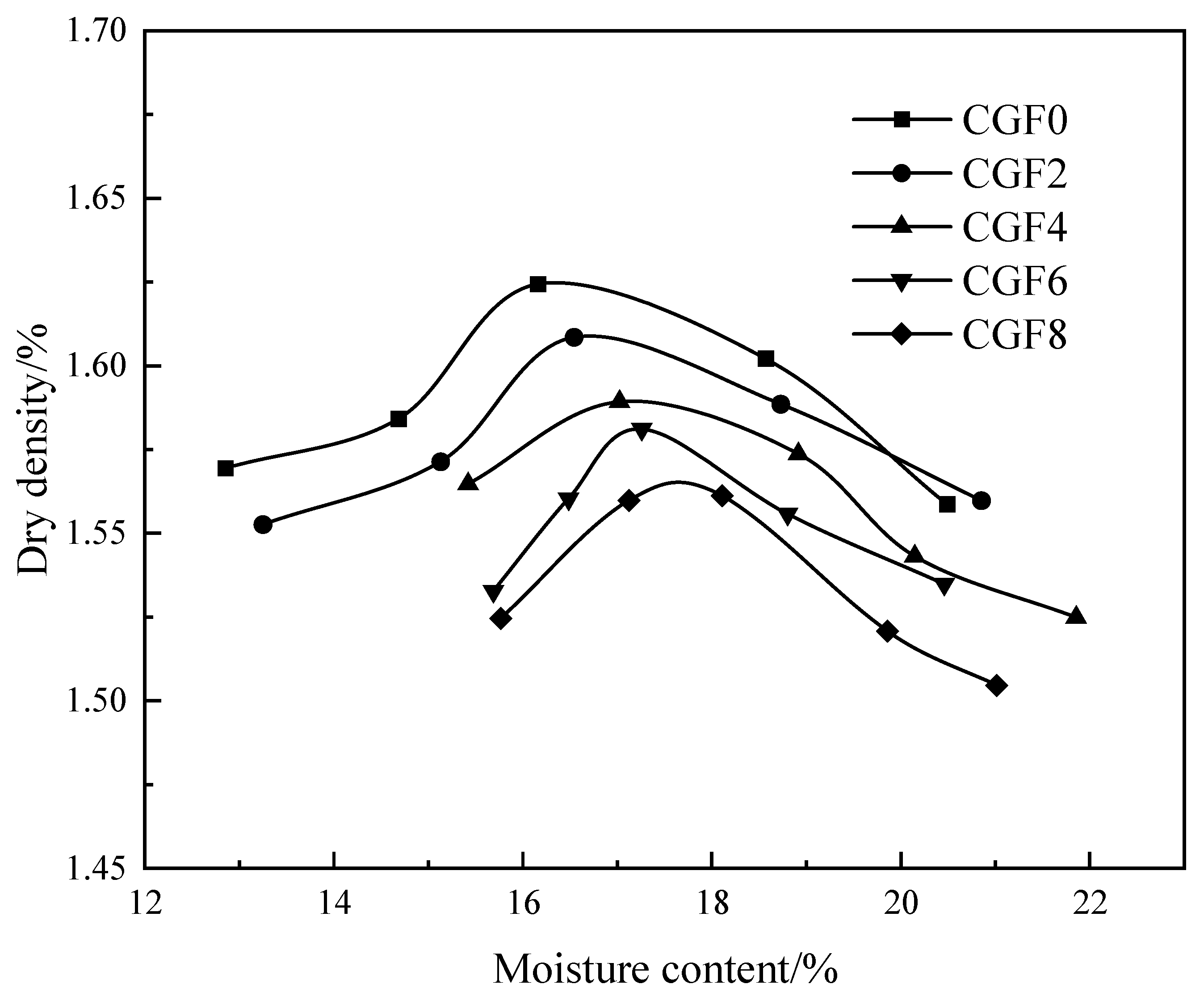
Figure 4 shows the compaction curves of the CGF semi-cured improved dredged soil. The dry density of the semi-cured improved dredged soil increases with increasing moisture content, reaches a maximum value, and then decreases as the moisture content continues to increase, exhibiting a peak value. As the curing agent content increases, the compaction curve shifts downward and to the right overall.
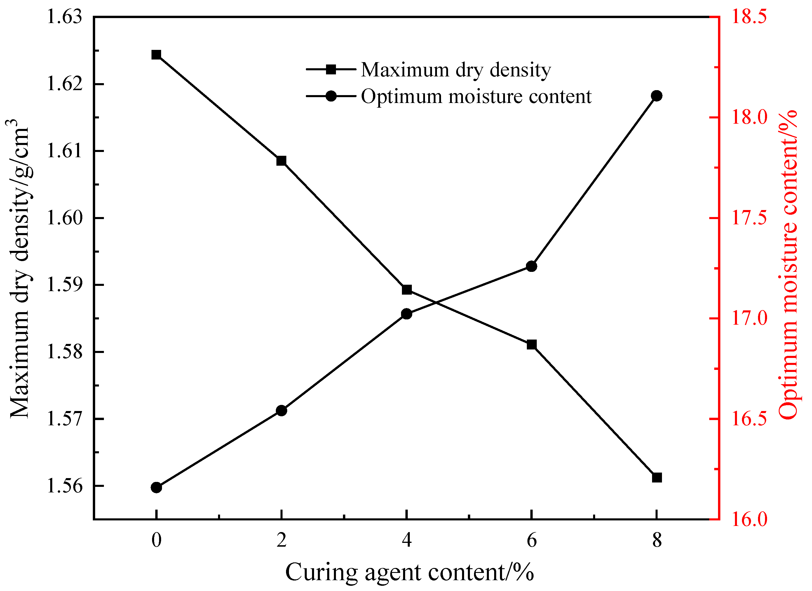
Figure 5 presents the variation curves of the maximum dry density and optimal moisture content of the CGF semi-cured improved dredged soil with different curing agent contents. It can be observed from the figure that, compared to the unimproved dredged soil, the maximum dry density of the semi-cured improved dredged soil decreases, while the optimal moisture content increases. With the increase in curing agent content, the maximum dry density of the semi-cured improved dredged soil further decreases, and the optimal moisture content further increases. Specifically, the maximum dry density decreases from 1.62 g/cm
3 at 0% content to 1.56 g/cm
3 at 8% content, and the optimal moisture content increases from 16.16% at 0% content to 18.11% at 8% content. This is because the incorporation of the curing agent triggers alkali-activated reactions that consume a portion of the water, leading to an increase in the optimal moisture content. Simultaneously, the cementitious products generated by the alkali-activated reactions not only make the soil more compact but also enhance the soil’s resistance to external forces, reducing the effectiveness of compaction and resulting in a decrease in the maximum dry density of the semi-cured improved dredged soil.
3.2. Changes in the Properties of Semi-Cured Improved Dredged Soil Under Freeze–Thaw Cycles
3.2.1. Mass Change
By measuring the mass change in the semi-cured improved dredged soil after freeze–thaw cycles, the influence of freeze–thaw cycles on the integrity of the semi-cured improved dredged soil was studied, and its freeze–thaw cycle resistance characteristics were further investigated. The mass loss rate was used to evaluate the effect of the number of cycles on the mass change in the semi-cured improved dredged soil. The mass loss rate was calculated according to the following Formula (1):
In the formula, Kₘ is the mass loss rate, %; m0 is the mass of the specimen before the freeze–thaw cycles, g; mₙ is the mass of the specimen after the nth freeze–thaw cycle, g.
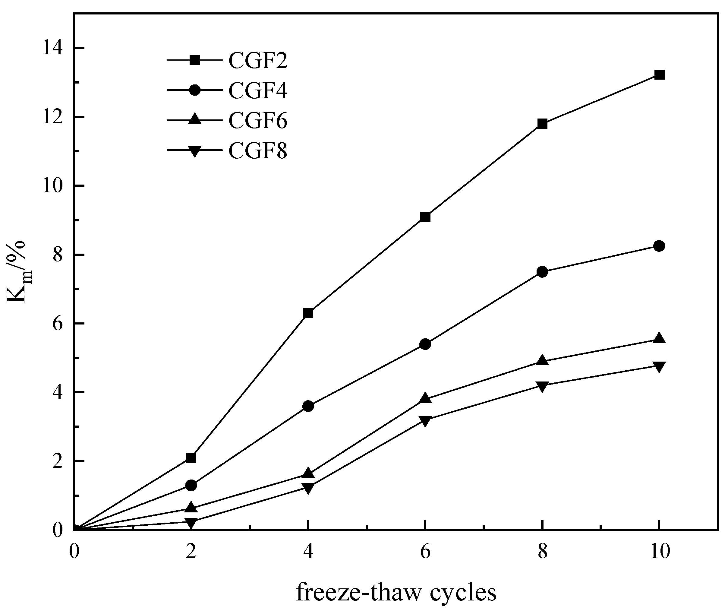
The variation in the mass loss rate of CGF semi-cured improved dredged soil with the number of freeze–thaw cycles is shown in
Figure 6. As the number of freeze–thaw cycles increases, the mass of the CGF semi-cured improved soil gradually decreases, and the mass loss rate gradually increases. It can also be seen from
Figure 6 that before undergoing 6 freeze–thaw cycles, the slope of the curve is relatively steep, indicating that the mass loss caused by freeze–thaw cycles is significant. After six freeze–thaw cycles, the curve gradually flattens, and the mass of the semi-cured improved soil tends to stabilize. After 10 freeze–thaw cycles, the mass loss rates of the CGF semi-cured improved dredged soil with curing agent contents of 2%, 4%, 6%, and 8% reached 13.22%, 8.25%, 5.54%, and 4.78%, respectively. This indicates that an increase in the curing agent content reduces the mass loss of the semi-cured improved soil, helping the specimen maintain its integrity. The change in the internal pore water of the semi-cured improved dredged soil under freeze–thaw cycles is the main reason for its mass loss. During the freezing process of the specimen, the freezing of internal pore water causes the volume of the specimen to increase, leading to deformation and structural damage. During the thawing process, the melting of internal pore water causes volume shrinkage. After repeated freezing and thawing, the internal pores of the specimen gradually enlarge, causing soil detachment and resulting in mass loss.
3.2.2. Change in Unconfined Compressive Strength
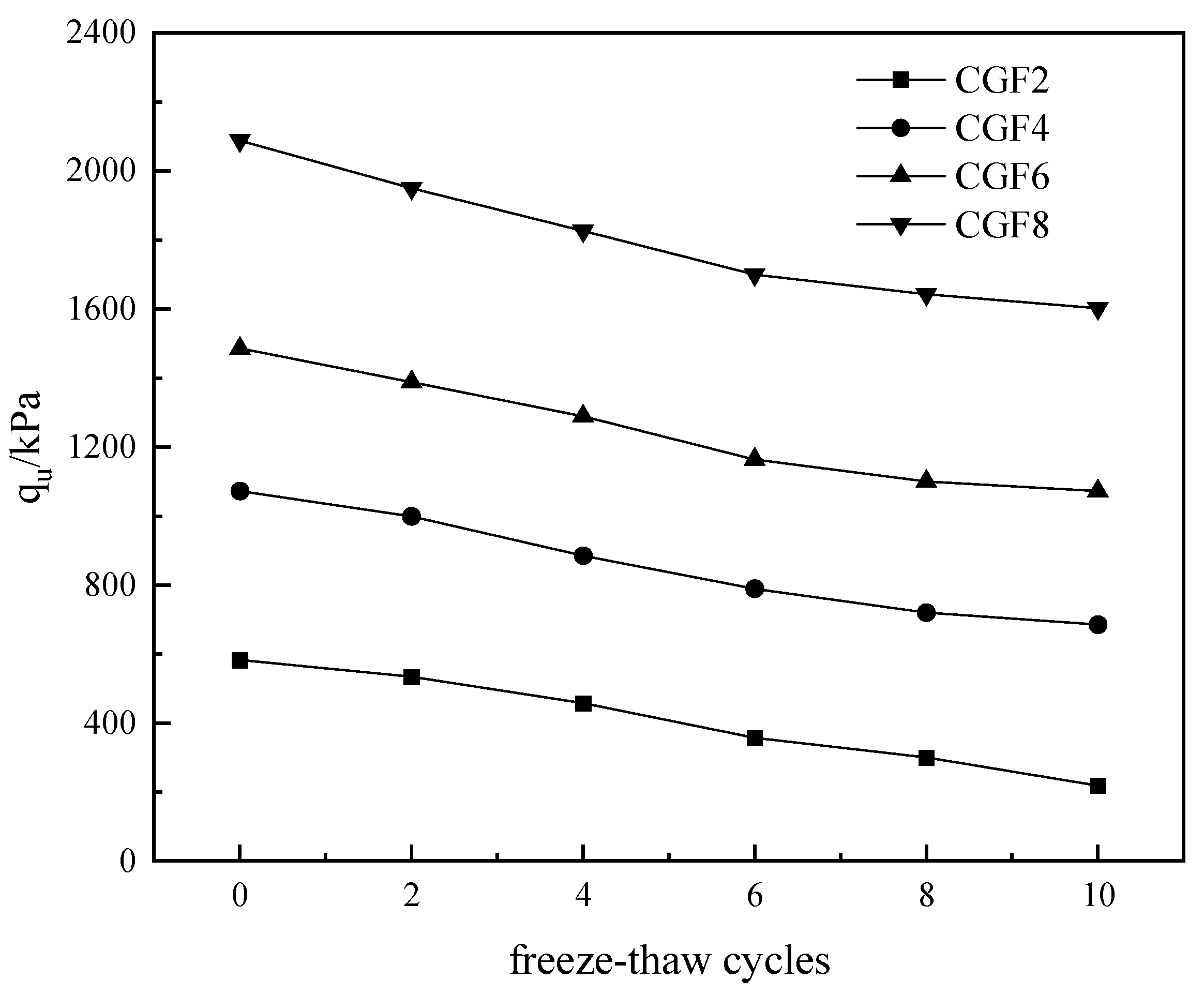
The variation pattern of the unconfined compressive strength of CGF semi-cured improved dredged soil with the number of freeze–thaw cycles is shown in
Figure 7. As the number of freeze–thaw cycles increases, the unconfined compressive strength of the semi-cured improved dredged soil gradually decreases. After 10 freeze–thaw cycles, the unconfined compressive strength of the specimens with curing agent contents of 2%, 4%, 6%, and 8% decreased from 582.4 kPa to 218.5 kPa, from 1072.5 kPa to 685.4 kPa, from 1486.1 kPa to 1072.4 kPa, and from 2088.7 kPa to 1602.3 kPa, respectively. This is because the freeze–thaw cycles cause the repeated freezing and thawing of bound water and free water within the specimen, which weakens the thickness of the bound water film, leads to pore development, and damages the internal structure, ultimately resulting in a decrease in strength. Additionally, the freeze–thaw cycles inhibit the alkali-activated reaction, which also contributes to the reduction in strength.
The strength loss rate was used to further evaluate the effect of freeze–thaw cycles on the strength of the semi-cured improved dredged soil. The strength loss rate of the specimen was calculated according to the following Formula (2):
In the formula, Kq is the strength loss rate of the specimen, %; q0 is the unconfined compressive strength of the specimen before freeze–thaw cycles, kPa; and qn is the unconfined compressive strength of the specimen after the nth freeze–thaw cycle, kPa.
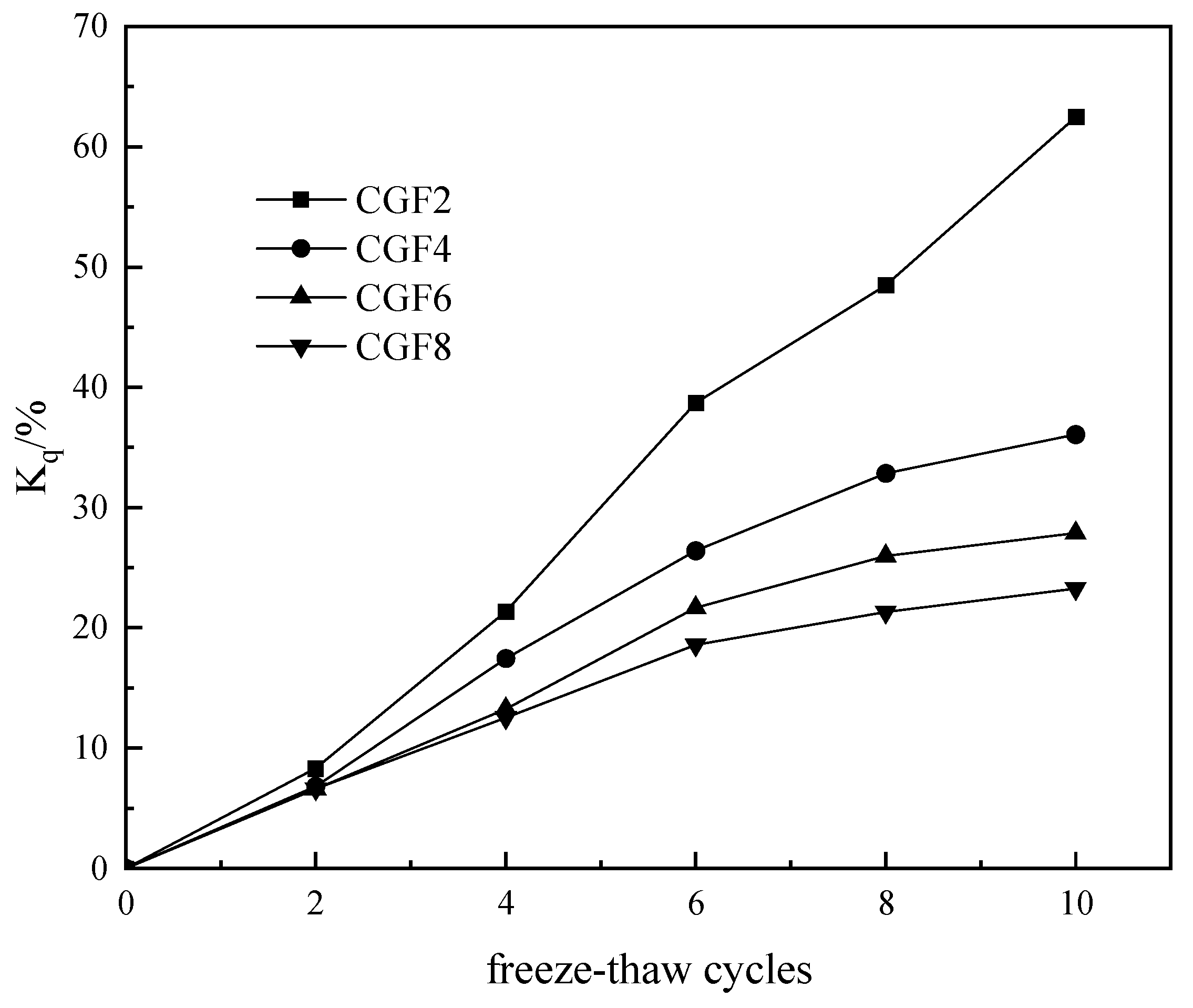
The variation pattern of the strength loss rate of semi-cured improved dredged soil with the number of freeze–thaw cycles is shown in
Figure 8. It can be observed from the figure that as the number of freeze–thaw cycles increases, the strength loss rate of the semi-cured improved dredged soil gradually increases, while the increasing trend gradually slows down. This indicates that increasing the curing agent content can enhance the frost resistance of the semi-cured improved dredged soil. After 10 freeze–thaw cycles, the strength loss rates of the specimens with curing agent contents of 2%, 4%, 6%, and 8% were 62.48%, 36.06%, 27.86%, and 23.27%, respectively. This demonstrates that the higher the curing agent content, the smaller the strength loss rate of the semi-cured improved dredged soil, and the stronger the frost resistance of the specimen.
3.3. Microscopic Results
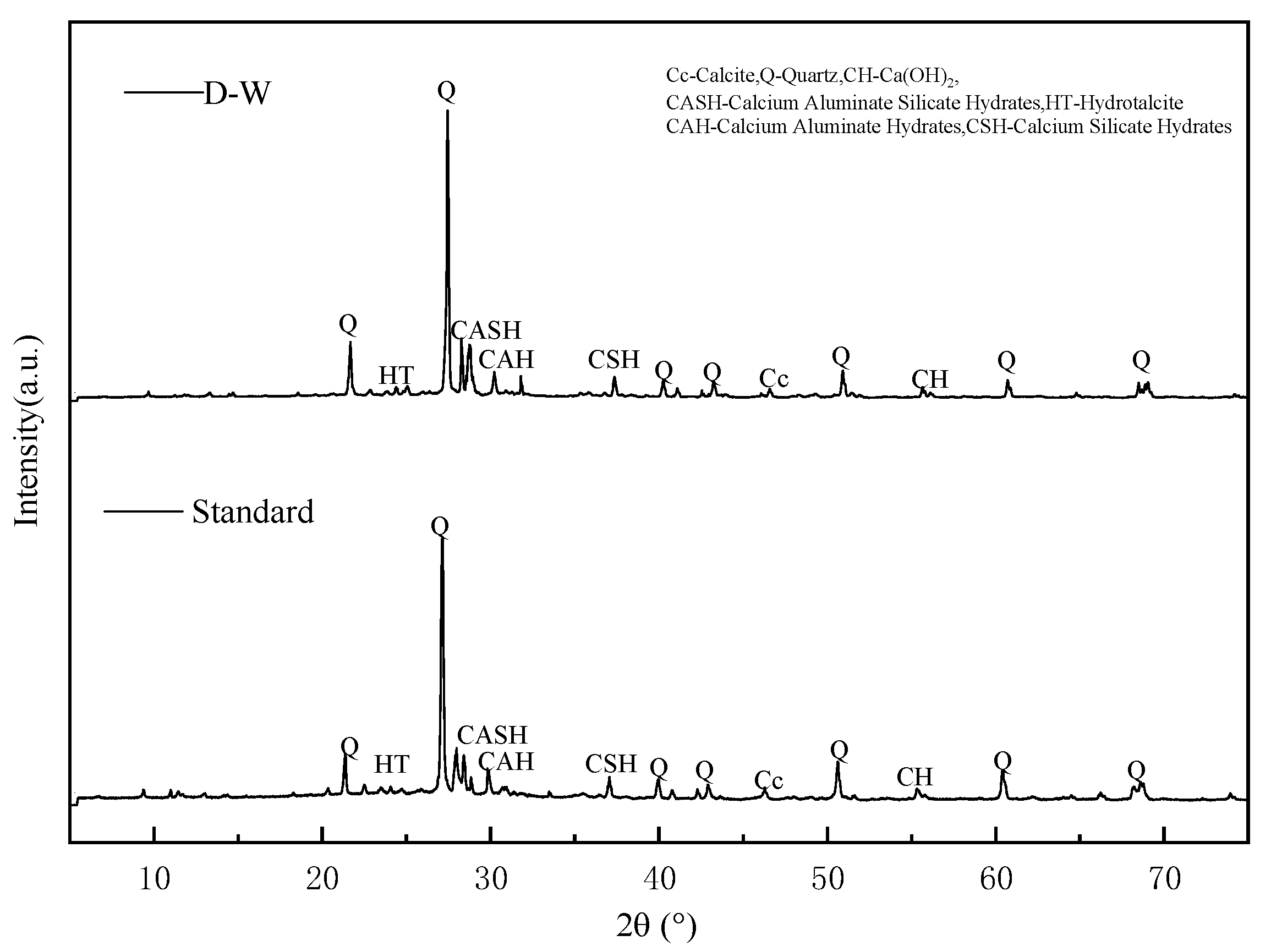
3.3.1. XRD Test
Figure 9 shows the XRD patterns of CGF semi-cured improved dredged soil under standard curing for 28 days and after 10 freeze–thaw cycles. It can be seen from the figure that the mineral composition of the specimen after 10 freeze–thaw cycles is essentially the same as that after 28 days of standard curing, primarily consisting of Quartz, C-A-H, C-S-H, and C-A-S-H, among others. Quartz can be clearly identified in the patterns; it is chemically stable and does not participate in the reaction process. C-A-H, C-S-H, and C-A-S-H are the main products of the alkali-activated reaction, enhancing soil strength by cementing soil particles and filling soil pores. Compared to the standard curing condition, the diffraction peak intensities of C-A-H, C-S-H, and C-A-S-H in the CGF semi-cured improved dredged soil after freeze–thaw cycles are slightly reduced, indicating that the freeze–thaw action damages the internal structure of the specimen, leading to a decrease in their content and also contributing to the attenuation of the specimen’s strength.
3.3.2. SEM Test
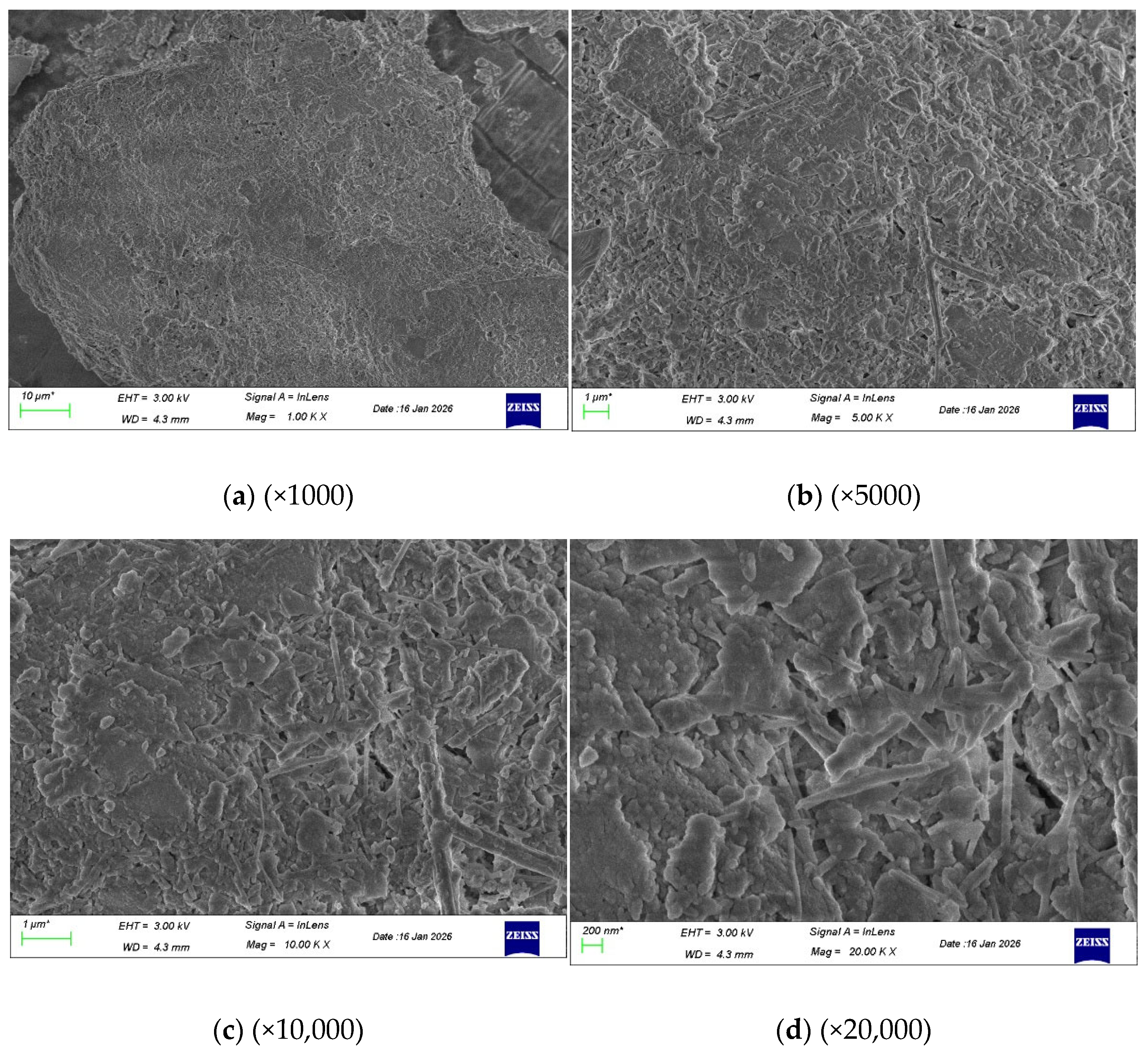
Figure 10 shows the SEM image of CGF semi-cured improved dredged soil with 8% curing agent content after 28 days of standard curing. It can be observed from the figure that a large number of alkali-activated products in flake form are distributed throughout the CGF semi-cured improved dredged soil. These hydration products interconnect and fill the pores, resulting in a dense soil structure and an increase in its strength.
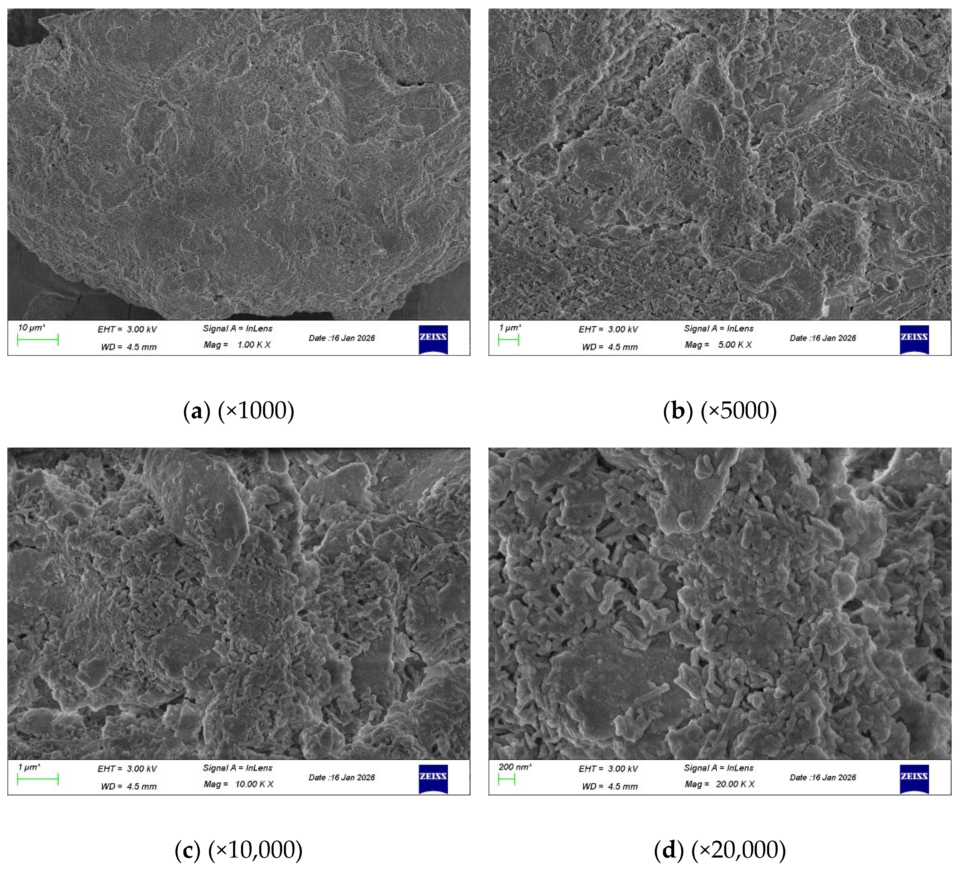
Figure 11 presents the SEM image of CGF semi-cured improved dredged soil with 8% curing agent content under the action of freeze–thaw cycles. Compared to the flake-shaped hydration products under standard curing conditions, the hydration products in the CGF semi-cured improved dredged soil after freeze–thaw cycles have transformed into a flocculent form. Additionally, the number of internal pores has increased, and the overall integrity has decreased. This is due to the repeated freezing and thawing of moisture inside the specimen during the freeze–thaw cycles. The frost heave pressure squeezes the soil particles, leading to an increase in soil porosity and ultimately causing damage to the specimen’s structure. Macroscopically, this is manifested as a reduction in the unconfined compressive strength of the specimen.
3.3.3. MIP Test
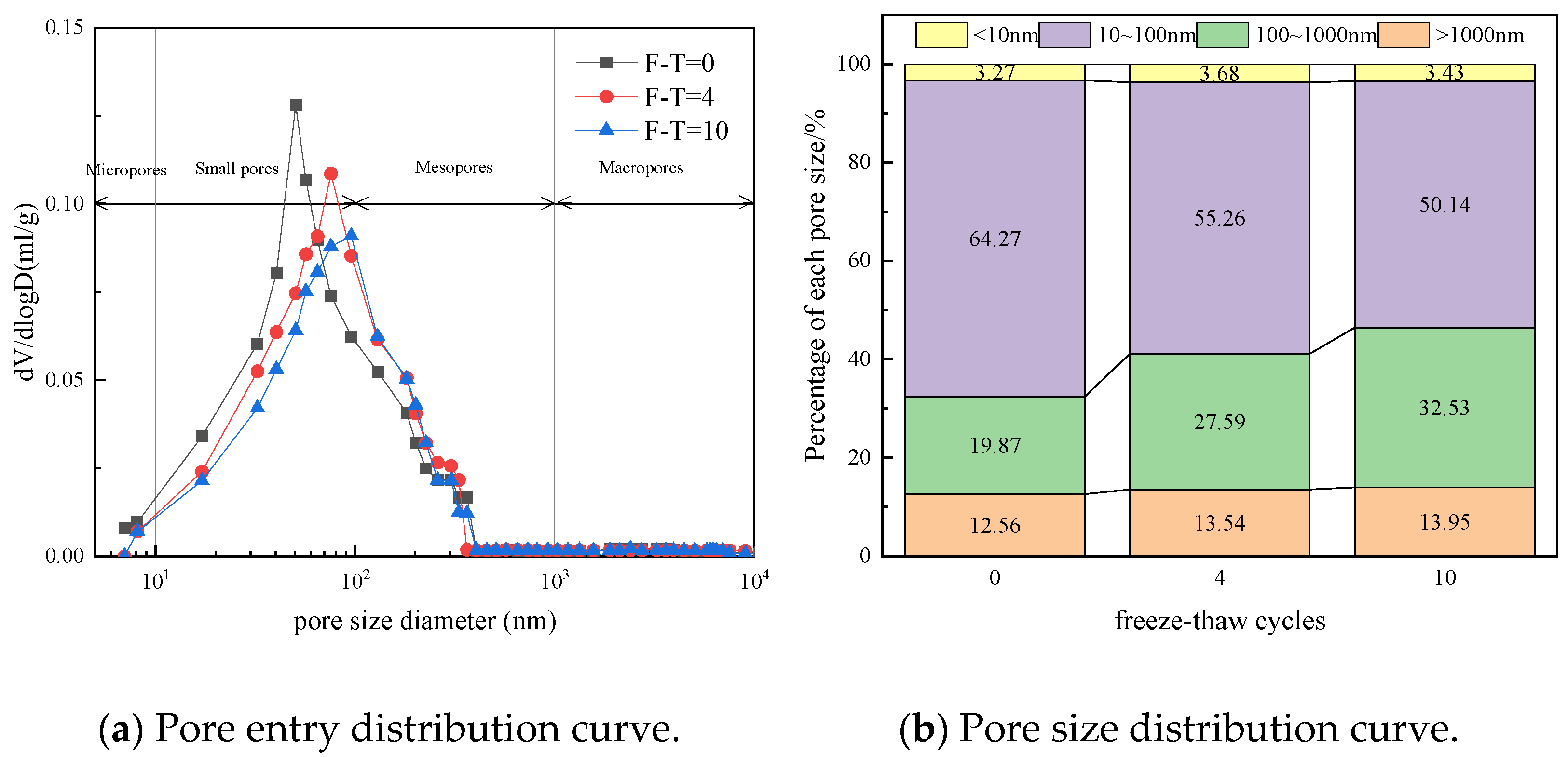
The pore size distribution curves of CGF semi-cured improved dredged soil are shown in
Figure 12. It can be seen from
Figure 12a that each curve has a main peak, and the pore size corresponding to the main peak is dominant. As the number of freeze–thaw cycles increases, the pore size of the main peak gradually increases. The main peak pore sizes after 4 freeze–thaw cycles and 10 freeze–thaw cycles are 75.65 nm and 95.59 nm, respectively, indicating that the freeze–thaw action leads to an increase in the pore size of the specimen and structural damage. This is consistent with the SEM results and is macroscopically manifested as a decrease in the strength of the specimen.
In this paper, the pore structure of the soil is divided into four categories based on pore size: micropores (<10 nm), small pores (10–100 nm), mesopores (100–1000 nm), and macropores (>1000 nm) [
29].
Figure 12b shows the pore size distribution of CGF semi-cured improved dredged soil under different numbers of freeze–thaw cycles. It can be seen from the figure that the pore structure of CGF semi-cured improved dredged soil is mainly composed of small pores and mesopores, with micropores accounting for 3.27%, small pores accounting for 64.27%, mesopores accounting for 19.87%, and macropores accounting for 12.56%. As the number of freeze–thaw cycles increases, the volume of small pores decreases, the volume of mesopores increases, and the volume of macropores does not change significantly. This indicates that freeze–thaw cycles enlarge the internal pores of the specimen, thereby affecting the internal pore distribution, which is consistent with the SEM results.
4. Conclusions
This study investigated the performance of CGF (calcium carbide slag, ground granulated blast furnace slag, and fly ash) semi-cured improved dredged soil under freeze–thaw cycles. The main findings and their practical implications are summarized as follows:
(1) Compaction behavior: Increasing the CGF content from 0% to 8% reduces the maximum dry density from 1.62 g/cm3 to 1.56 g/cm3 and raises the optimum moisture content from 16.16% to 18.11%. Practical implication: Field compaction of CGF-treated dredged soil requires higher moisture content and greater compactive energy than untreated soil.
(2) Mass stability under freeze–thaw: Mass loss rate increases with the number of freeze–thaw cycles but decreases with higher CGF content. After 10 cycles, mass loss rates for 2%, 4%, 6%, and 8% CGF specimens are 13.22%, 8.25%, 5.54%, and 4.78%, respectively. Practical implication: A minimum CGF content of 6% is recommended for applications where mass integrity is critical under seasonal freezing conditions.
(3) Strength retention: Unconfined compressive strength decreases progressively with freeze–thaw cycles, while strength loss rate decreases with higher binder content. After 10 cycles, strength loss rates for 2%, 4%, 6%, and 8% CGF specimens are 62.48%, 36.06%, 27.86%, and 23.27%, respectively. Practical implication: The CGF binder significantly enhances frost resistance; 8% CGF content provides optimal strength retention, reducing strength loss by approximately 39 percentage points compared to 2% CGF.
(4) Microstructural mechanism: Pore structure degradation—specifically, the decrease in small pores (10–100 nm) and increase in mesopores (100–1000 nm)—is the underlying cause of macroscopic strength loss. Practical implication: The frost resistance of CGF-treated soil is governed by the stability of its pore network; mix designs targeting pore refinement will yield better durability.
In summary, the CGF all-solid-waste binder offers an environmentally sustainable alternative to conventional cement/lime stabilization for dredged soil in seasonally frozen regions, with 6–8% CGF content recommended for subgrade applications requiring frost resistance.
Author Contributions
Conceptualization, T.H.; methodology, J.Y.; formal analysis, Y.W.; investigation, T.H.; resources, J.Y.; data curation, T.H.; writing—original draft preparation, T.H.; writing—review and editing, T.H., J.Y. and Y.W.; supervision, J.Y. and T.H.; project administration, Y.W.; funding acquisition, J.Y. All authors have read and agreed to the published version of the manuscript.
Funding
Supported by the National Natural Science Foundation of China (42507220, 52378380, 52078474).
Institutional Review Board Statement
Not applicable.
Informed Consent Statement
Not applicable.
Data Availability Statement
The data presented in this study are available upon request from the corresponding author. The data are not publicly available due to the confidentiality of the research subject.
Conflicts of Interest
The authors declare no conflicts of interest.
References
- Wu, W.; Gu, L.; Wang, S.; Wu, Z.; Zhang, Q.; Zhu, F.; Hai, T. Experimental Study on Mechanical Properties of Dredged River Sediments Solidified by Industrial Solid Waste-Based Geopolymer. J. Disaster Prev. Mitig. Eng. 2025, 45, 643–651. [Google Scholar]
- Zhu, W.; Zhang, C.; Gao, Y.; Fan, Z. Fundamental mechanical properties of solidified dredged marine soil. J. Zhejiang Univ. (Eng. Sci.) 2005, 39, 103–107. [Google Scholar]
- Xiao, W.; Chen, Y.; Zhang, W.; Wang, T. Application research on treatment of waterway dredged soil as subgrade filling. Constr. Technol. 2016, 45, 356–359. [Google Scholar]
- Shi, C.; Tang, X.; Lin, T. Study on Dredged Soil as Anti-Seepage Material for Clay Liner of Landfill. Chin. J. Rock Mech. Eng. 2004, 23, 4418–4421. [Google Scholar]
- Cheng, H.; Liu, J.; Chen, F.; Zhao, D. Comprehensive utilization of dredged soil from the Yangtze Estuary waterway during the 14th Five-Year Plan period. Resour. Environ. Yangtze Basin 2023, 32, 331–338. [Google Scholar]
- Rajasekaran, G.; Narasimha Rao, S. Compressibility behaviour of lime-treated marine clay. Ocean Eng. 2002, 29, 545–559. [Google Scholar] [CrossRef]
- Kang, G.; Tsuchida, T.; Athapaththu, A.M.R.G. Engineering behavior of cement-treated marine dredged clay during early and later stages of curing. Eng. Geol. 2016, 209, 163–174. [Google Scholar] [CrossRef]
- Liu, Q.; Yang, J.; Wu, Y.; Wang, Z.; Qiu, X.; Yan, L. Physical and Mechanical Properties of All-Solid-Waste-Based Binder-Modified Abandoned Marine Soft Soil. J. Mar. Sci. Eng. 2024, 12, 393. [Google Scholar] [CrossRef]
- Su, X.; Yang, J.; Dong, M.; Wu, W. Study on engineering properties of cement semi-solidified soil. Period. Ocean Univ. China. 2020, 50, 134–140. [Google Scholar]
- Wu, Y.; Yang, J.; Chang, R.; Li, S.; Kou, H. Strength, leaching characteristics and microstructure of CGF plus P all-solid-waste binder solidification/stabilization Cu(II) contaminated soil. Constr. Build. Mater. 2024, 411, 134431. [Google Scholar] [CrossRef]
- Wu, Y.; Yang, J.; Chang, R. The design of ternary all-solid-waste binder for solidified soil and the mechanical properties, mechanism and environmental benefits of CGF solidified soil. J. Clean. Prod. 2023, 429, 139439. [Google Scholar] [CrossRef]
- Hou, X.; Fan, H.; Huang, J. Study on long-term strength deterioration law and micro-mechanism of solidified plateau soft soil under freeze-thaw cycles. Chin. J. Rock Mech. Eng. 2025, 44, 1–13. [Google Scholar]
- Jin, H.S.; Li, F.H.; He, X.Y.F.; Wang, J.S.; Hu, D.H.; Hu, Z.M. Study on frost resistance of polypropylene fiber cement-based composites. Mater. Rep. 2020, 34, 8071–8076. [Google Scholar]
- Zhu, Y.; Yu, H.; Yang, Y. Laboratory experimental study on properties of improved red mudstone soil. Chin. J. Rock Mech. Eng. 2013, 32, 425–432. [Google Scholar]
- Dong, C.; Leng, W.; Li, Z. Experimental study of dynamic resilient modulus of cement-improved high liquid limit clay. Rock Soil Mech. 2013, 34, 133–138. [Google Scholar]
- Zhang, Y.; Wang, X.; Yin, Y. Experimental research on cement-improved phyllite spoil as railway subgrade filling. J. China Railw. Soc. 2014, 36, 81–86. [Google Scholar]
- Shang, Y.; Xu, L.; Liu, W. Engineering characteristics and road performance of cement-improved expansive soil for heavy haul railway. J. Southwest Jiaotong Univ. 2020, 55, 1044–1051. [Google Scholar]
- Cao, J.; He, Q.; Ge, X. Study on strength characteristics and microscopic mechanism of lime-improved clay. J. Nat. Disasters 2025, 34, 159–170. [Google Scholar]
- Cui, W.; Li, H.; Mu, N. Experimental study on engineering properties of lime-modified expansive soil. Rock Soil Mech. 2003, 24, 606–609. [Google Scholar]
- Li, X.; Zhang, H.; Wu, D. Freeze-thaw cycling effect on strength deterioration characteristics of lime-metakaolin modified relic soil. Rock Soil Mech. 2023, 44, 1593–1603. [Google Scholar]
- Tao, Z.; Zhang, Y.; Chen, X.; Gu, X. Effects of freeze-thaw cycles on the mechanical properties of cement-fiber composite treated silty clay. Constr. Build. Mater. 2022, 316, 125867. [Google Scholar] [CrossRef]
- Yousefi, A.; Jahanian, H.; Azadi, M. The effect of freeze-thaw cycles on mechanical properties of fine-grained soil modified by cement and nanocement. Sci. Iran. 2022, 29, 2940–2952. [Google Scholar]
- Rong, S.; Yan, Z.; Yang, L. Effect of freeze-thaw cycles on strength of cement-improved weathered sand. Jiangxi Build. Mater. 2021, 8, 19–20. [Google Scholar]
- Ruan, B.; Shen, Y.; Zhang, X. Dynamic characteristics of fiber-cement improved aeolian sand under freeze-thaw cycles. J. Railw. Sci. Eng. 2025, 22, 1614–1621. [Google Scholar]
- Xu, C.; Ruan, B. NMR experimental study on fiber-cement improved aeolian sand under freeze-thaw cycles. J. Railw. Sci. Eng. 2021, 18, 2289–2298. [Google Scholar]
- Zhang, S.; Shao, S.; Shao, S. Three-dimensional mechanical properties of saline cement-improved aeolian sand under freeze-thaw cycles. J. Basic Sci. Eng. 2024, 32, 1648–1658. [Google Scholar]
- GB/T50123-2019; Ministry of Housing and Urban-Rural Development of the People’s Republic of China. Standard for Geotechnical Testing Method. China Planning Press: Beijing, China, 2019.
- GB/50007-2011; Ministry of Housing and Urban-Rural Development of the People’s Republic of China. Code for Design of Building Foundation. China Architecture & Building Press: Beijing, China, 2011.
- Huang, J.; Zhang, Y.; Sun, Y.; Ren, J.; Zhao, Z.; Zhang, J. Evaluation of pore size distribution and permeability reduction behavior in pervious concrete. Constr. Build. Mater. 2021, 290, 123228. [Google Scholar] [CrossRef]
| Disclaimer/Publisher’s Note: The statements, opinions and data contained in all publications are solely those of the individual author(s) and contributor(s) and not of MDPI and/or the editor(s). MDPI and/or the editor(s) disclaim responsibility for any injury to people or property resulting from any ideas, methods, instructions or products referred to in the content. |