Article

Multi-Objective Optimization of Variable-Pitch Domino Wireless Power Transfer Coils for 66 kV High-Voltage Insulator Strings

1
School of Electrical Engineering, China University of Mining and Technology, Xuzhou 221116, China
2
Sustainable Energy and Environment Thrust, Hong Kong University of Science and Technology (Guangzhou), Guangzhou 511453, China
3
Department of Electrical Engineering, Qingdao University, Qingdao 266000, China
4
School of Electrical Engineering, Southwest Jiaotong University, Chengdu 611756, China
5
Department of Electrical Engineering, Federal University of Campina Grande, Campina Grande 58429-900, Paraiba, Brazil
*
Author to whom correspondence should be addressed.
These authors contributed equally to this work.
Appl. Sci. 2026, 16(11), 5241; https://doi.org/10.3390/app16115241
Submission received: 1 April 2026 / Revised: 15 May 2026 / Accepted: 21 May 2026 / Published: 23 May 2026

Abstract

Wireless power transfer (WPT), characterized by its excellent insulation properties and ease of maintenance, has recently emerged as a promising solution to the power supply challenges faced by online monitoring equipment on high-voltage transmission towers in complex environments. Existing research primarily relies on regular, closely wound solenoids to power these monitoring devices; however, this approach often makes it difficult to optimize the magnetic field distribution to maximize mutual inductance, thereby limiting transmission efficiency and power and hindering lightweight design. To address these issues, this paper proposes an optimized design scheme for variable-pitch (non-uniform) domino WPT coils based on insulator string structures. First, a parameter calculation model utilizing segmented current analysis is constructed to accurately determine the inductance of non-uniform solenoids, with simulations confirming an error rate below 5%. Subsequently, by integrating domino multi-coil theory into an elitist non-dominated sorting genetic algorithm (NSGA-II), dual-objective optimization is performed. Targeting maximum transmission efficiency and output power under spatial and insulation constraints, a set of Pareto optimal solutions is derived. Ultimately, a 113.7 W insulator domino coil WPT system prototype is constructed to validate the design’s stability. The proposed system achieves a maximum efficiency of 85.73%, with a single-stage load delivering up to 97.48 W.

1. Introduction

With the rapid advancement of smart grid digitalization, online monitoring technology for high-voltage transmission towers and lines has become a core pillar for ensuring the safe and stable operation of power grids [1]. As monitoring equipment operates continuously in complex high-voltage outdoor environments, achieving reliable and sustained power supply has emerged as a critical bottleneck for technological implementation [2]. Current power supply solutions, such as solar energy and batteries, suffer from significant environmental susceptibility or high maintenance costs [3]. Furthermore, strict insulation distance requirements between high-voltage and low-voltage sides preclude the direct application of traditional wired power supply methods [4].
Studies have shown that the Domino Resonant Inductive Coupling wireless power transfer (DR-IPT) system, leveraging relay coil-based energy transfer and contactless power delivery, has emerged as the preferred solution for long-distance insulated power supply [5,6]. The technology’s core lies in embedding coils within insulator strings to establish an energy pathway from the high-voltage side to monitoring equipment [7]. Research confirms that this topology, when integrated with insulators, does not significantly alter the original electric and magnetic field distributions, making it highly compatible with high-voltage transmission environments [8,9].
In recent years, researchers worldwide have conducted extensive research on domino insulator string coils: Cai et al. proposed embedding resonant coils within 110 kV composite insulators, simplifying the structure using PCB technology and passing high-voltage testing [10]; Qu et al. designed a domino system based on PCB resonators, achieving effective energy transmission over a 1.14 m distance [11]; Li et al. optimized single-layer uniformly spaced coils using a particle swarm optimization algorithm, achieving 85.94% transmission efficiency at 50 cm [12]; Yazdi et al. addressed interference from external metallic objects (EMOs) by establishing corresponding circuit models and optimization methods [13].
However, while the aforementioned research has laid the foundation for engineering applications, significant limitations remain. Existing designs predominantly rely on regular, closely wound solenoid coils [14]; this uniform approach struggles to optimize the magnetic field distribution and coupling between the coils, thereby limiting the system’s overall power transmission capacity and efficiency. Theoretically, employing non-uniform pitch designs can effectively improve the magnetic field distribution, enhancing both power transmission capacity and efficiency while facilitating a more lightweight design [15]. However, systematic modeling and experimental validation for such variable-pitch coils applied within domino insulator strings are still lacking.
Furthermore, computational models for key parameters such as resonance frequency and resistance of irregular structures [16] have yet to be effectively integrated with the coupling characteristics of domino multi-coils, limiting further system performance optimization. Previous work can be broadly categorized into three streams in mutual inductance and ef-ficiency optimization for WPT relay chains. The first stream focuses on analytical and numerical methods for inductance characterization, including Neumann’s formula [15], the Biot-Savart-based segmented current approach [16], and FEM-assisted surrogate mod-eling. The second stream covers system-level optimization, such as adjusting relay coil spacing [11], compensation network design [17], and operating frequency selection to maximize transmission efficiency or output power under fixed coil geometries. The third stream addresses coil geometry optimization, including studies on pitch modulation in solenoid coils for general inductive power transfer and DD-type coil designs for biomedi-cal WPT [15].
For a multi-stage domino relay chain, the critical coupling region for inter-stage en-ergy transfer is precisely the air gap between adjacent coils, which corresponds to the low-flux midpoint region of each coil. By redistributing the wire density in a non-uniform pitch pattern—concentrating turns at the axial ends where coupling to the adjacent relay coil is geometrically strongest—a variable-pitch geometry can actively shape the spatial magnetic flux distribution to maximize inter-stage mutual inductance within a fixed axial envelope. This fundamentally distinguishes it from conventional uniform-pitch designs, which offer no geometric degree of freedom for flux management once the total wire length and winding radius are fixed.
Against this backdrop, this paper proposes an optimization design scheme for non-uniform solenoid coils in insulator strings based on the elitist non-dominated sorting genetic algorithm (NSGA-II) algorithm [18]. The core research approach is as follows: First, construct a parameter calculation model suitable for irregular solenoids [16] to precisely determine the coil inductance (L) and distributed parameters under non-uniform structures, overcoming the shortcomings of traditional empirical formulas such as poor adaptability and high computational cost; Second, by integrating domino multi-coil transmission theory, a dual-objective optimization function is established with “maximizing transmission efficiency” and “maximizing output power” as targets, incorporating spatial dimensional constraints of the insulator string and high-voltage insulation clearances as boundary conditions; Finally, the NSGA-II algorithm is employed to obtain the Pareto front, identifying the optimal coil distribution scheme that balances efficiency and power. This enables precise layout of each coil turn on the insulator string, with experimental validation confirming the feasibility and superiority of this approach.
This work has systematically integrated a physics-accurate analytical model for var-iable-pitch inductance with a multi-objective optimization framework under the unique dual constraints of 66 kV insulator strings, namely strict creepage distances and rigid shed-to-shed spatial boundaries. This constitutes the primary research gap addressed by the present paper.
The specific contributions of this paper are summarized as follows:
(1)
A novel numerical integration model based on segmented current analysis is devel-oped to accurately compute the self-inductance, mutual inductance, and AC resistance of non-uniform variable-pitch solenoid coils, achieving a calculation error below 5% across the full operational parameter space—a capability not achievable with conventional em-pirical formulas.
(2)
This physics-accurate model is systematically integrated into an NSGA-II mul-ti-objective optimization framework specifically tailored for the dual constraints of 66 kV insulator strings, yielding a Pareto-optimal pitch distribution that simultaneously max-imizes transmission efficiency and output power.
(3)
Experimental validation on a five-stage prototype confirms 85.73% transmission effi-ciency and 97.48 W output power, with errors of only 1.1% and 2.4% relative to theoretical predictions, demonstrating both the accuracy of the analytical model and the engineering feasibility of the proposed design methodology.

2. Wireless Power Supply System for High-Voltage Transmission Towers

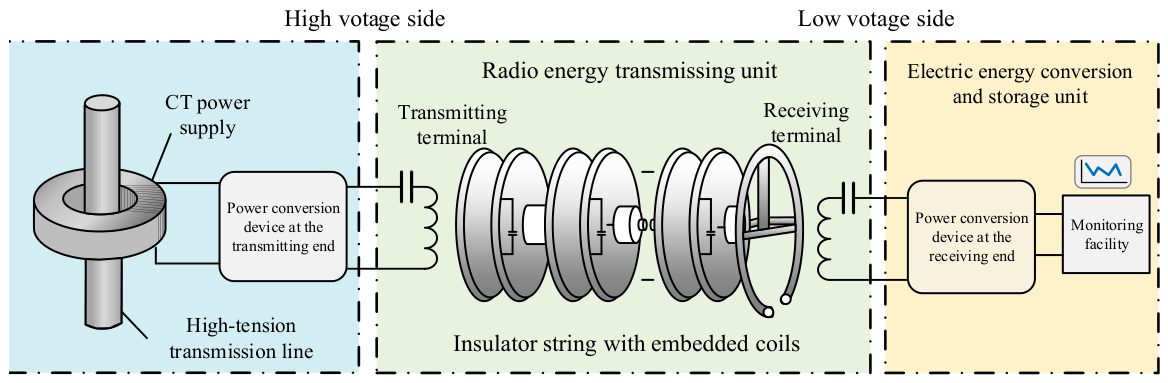
The wireless power supply system architecture for online monitoring equipment on high-voltage transmission towers is shown in Figure 1.
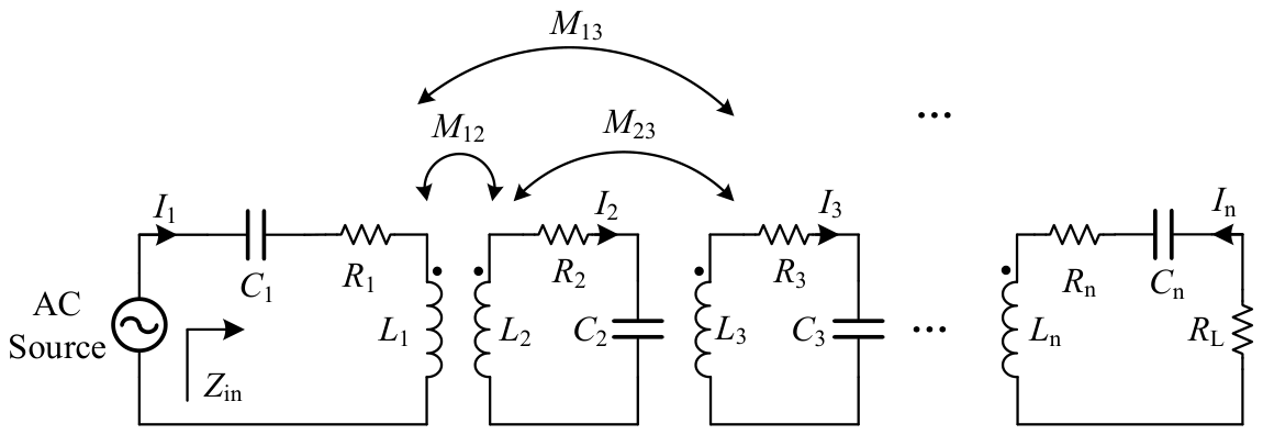
The system captures electrical energy from high-voltage transmission lines via current transformer (CT) power extraction devices. After converting power from utility frequency to high-frequency through the transmitter-side power conversion unit, wireless power transmission is achieved by a unit comprising a transmitter coil, multiple relay coils, and a receiver coil. Upon reaching the receiving end, the energy is processed by the receiving-end power conversion unit, transforming it into a stable and reliable low-voltage DC power supply to provide continuous power to monitoring equipment. The system utilizes insulator strings as the load-bearing carrier for the wireless power supply system coupling mechanism between the CT power extraction device and the online monitoring equipment, with each resonant coil wound around the outer skirt of the insulator. This paper focuses exclusively on the wireless power transmission unit within the wireless power supply system. Research on the high-voltage power extraction and conversion unit and the power conversion and storage unit will be addressed in subsequent work. To simplify the analysis process, this study models the CT power extraction device and the transmitter-side power conversion device as an equivalent high-frequency AC voltage source Uin . Simultaneously, the receiver-side power conversion device and the monitoring equipment are modeled as an equivalent load RL. The equivalent circuit is shown in Figure 2.

3. Theoretical Analysis of the Domino Unit WPT System

To evaluate the transmission performance of variable-pitch coils in a domino system, this paper establishes an equivalent circuit model based on mutual coupling theory. This model transforms complex electromagnetic field problems into circuit network problems, enabling rapid determination of the system’s current distribution, output power, and transmission efficiency by solving the KVL (Kirchhoff’s Voltage Law) matrix equations.

3.1. Equivalent Circuit Topology of the Multi-Coil Domino System

The system consists of a transmitter, multiple relay coils, and a receiver. To compensate for the inductive reactive power of the coils, a series-series (S-S) compensation topology [19] is employed. This topology exhibits insensitivity to load variations and features capacitance values dependent solely on self-inductance and frequency, making it suitable for fixed-structure applications such as high-voltage insulator strings.
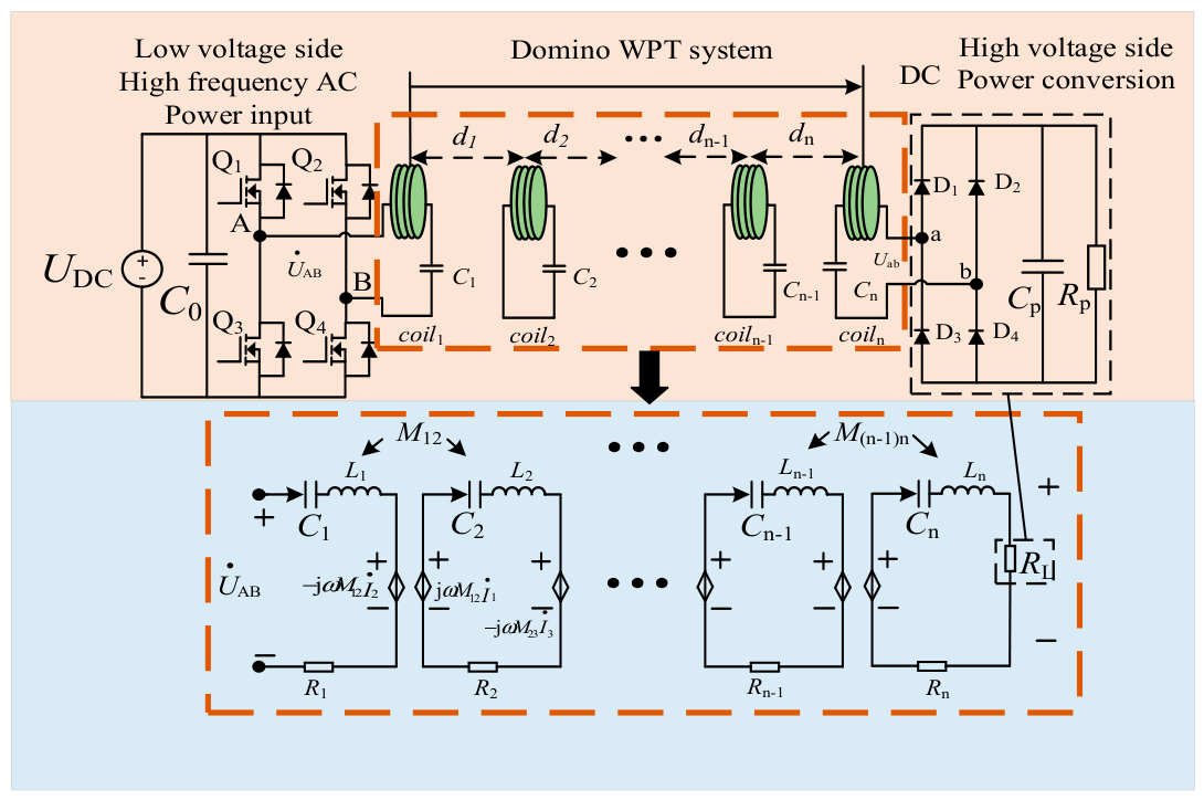
Figure 3 shows Schematic Diagram of Domino Resonant WPT System. The equivalent circuit of the system consists of three main sections. Loop 1 includes the power source, source internal and coil resistance R 1 , transmitter coil L 1 , compensation capacitor C 1 , and the coil’s internal resistance. Loop i acts as the relay loop, comprising the relay coil Li, compensation capacitor Ci, and internal resistance R i . Finally, Loop n represents the receiver loop, containing the receiver coil L n , compensation capacitor C n , internal resistance R n , and the equivalent load resistance RL.

3.2. Construction of KVL Matrix Equations

Based on KVL, the loop current equations are established for the n coil loops. Considering that the domino system features not only strong coupling between adjacent coils ( M i , i + 1 ) but also weak cross-coupling between non-adjacent coils ( M i , j ,   i j > 1 ), the system impedance matrix equation can be expressed as:
U ˙ i n 0 0 = Z 1 j ω M 12 j ω M 1 n j ω M 21 Z 2 j ω M 2 n j ω M n 1 j ω M n 2 Z n + R L I ˙ 1 I ˙ 2 I ˙ n ,
where ω = 2 π f is the operating angular frequency of the system. It should be noted that the self-impedance Z i and mutual impedance jωMij are complex measures. Furthermore, to standardize the rigorous representation of complex quantities, the phasor input voltage U ˙ i n and phasor currents I ˙ i are properly represented with dot notation. Z i is the self-impedance of the i -th loop, expressed as:
Z i = R i + j ω L i 1 ω C i .
For the transmitter loop ( i = 1 ), R 1 must include the internal resistance of the power source R d ; for other loops, R i is the internal resistance of the coil. M i j is the mutual inductance between coil i and coil j .

3.3. Simplified Solution in Resonance State

To achieve efficient transmission, the optimization algorithm is configured to ensure that the system consistently operates in a fully resonant state. According to Equation (2), the inductive reactance and capacitive reactance of each circuit cancel each other out at this point:
ω L i 1 ω C i = 0 Z i R i .

3.4. Performance Metrics

After obtaining the RMS value of each loop current I i = I i ˙ , the performance metrics of each candidate solution in the current iteration can be calculated and used as the objective function inputs for NSGA-II:
Output Power P o u t : Defined as the received power obtained on the load resistance R L .
P o u t = I n 2 R L .
This metric reflects the system’s power supply capacity for monitoring equipment and is one of the core objectives of optimization.
Transmission Efficiency η : Defined as the ratio of output power to the total input power of the system. The input power P i n is equal to the sum of the resistance losses of all loops and the output power.
P i n = i = 1 n I i 2 R i + I n 2 R L .
The transmission efficiency expression is:
η = I n 2 R L i = 1 n I i 2 R i + I n 2 R L × 100 % .

4. Modeling and Parameter Calculation of Variable Pitch Domino Coils

The fundamental novelty of the proposed numerical integration model must be highlighted. Traditional WPT optimization heavily relies on empirical formulas that are exclusively applicable to uniform, closely wound solenoids. These conventional models inherently fail to accurately capture the highly complex, non-linear magnetic field distributions generated by irregular structures. In contrast, the methodology developed in this study utilizes segmented current analysis to precisely compute the internal/external inductance and the spatial magnetic flux mapping of non-uniform, variable-pitch structures. This theoretical breakthrough breaks the geometric limitations of conventional WPT designs.

4.1. Geometric Characterization of Spiral Tubes

4.1.1. Physical Model Definition

The variable-pitch solenoid studied in this paper is defined as a cylindrical structure where the coil radius R c remains constant, but the pitch p between adjacent turns changes with the axial position, resulting in a non-uniform wire distribution. Unlike traditional uniformly wound solenoids, variable-pitch solenoids possess greater geometric freedom. The physical model is constructed based on two primary assumptions. First, the geometric central axis of the coil coincides with the z -axis, with the magnetic field analysis focusing primarily on the axial component B z . Second, the coil consists of N turns, where the pitch p i of each individual turn serves as an independently adjustable design variable.

4.1.2. Parametric Equations of a Spiral Curve

To precisely describe the spatial morphology of a helical tube, a cylindrical coordinate system is established. For a multi-turn coil with radius r, its spatial geometric trajectory can be described by the following parametric equations:
x ( t ) = R c cos ( t ) , y ( t ) = R c sin ( t ) .
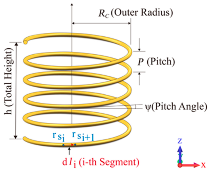
Geometric Configuration and Key Parameters of Coils with Fixed Pitch p is shown in Figure 4. In the axial direction, the equation for a traditional uniform solenoid is z ( t ) = p t / ( 2 π ) . However, for variable-pitch solenoids, the pitch p is no longer a constant but a function that varies with the number of turns. This paper employs a discrete segmented description method, dividing the coil into independent pitch segments. The axial height increase in the i -th turn coil is determined by the local pitch p i of that turn. The spatial geometric trajectory of the i -th turn coil can be described by the following piecewise parametric equation:
C i ( θ ) = x ( θ ) = R c cos ( θ ) y ( θ ) = R c sin ( θ ) z ( θ ) = Z i 1 + p i / 2 π [ θ 2 π ( i 1 ) ] ,
where θ denotes the cumulative rotation angle. For the i -th turn of the coil, the range of θ is defined as 2 π i 1 ,   2 π i .
The parameter Z i 1 represents the initial axial height of the i -th turn, which is equivalent to the cumulative sum of the local pitches of the preceding i 1 turns. This relationship can be mathematically expressed as:
Z i 1 = k = 1 i 1 p k .

4.1.3. Discretization of Pitch Distribution and Design Variables

To apply the geometric representation to the NSGA-II optimization algorithm, the continuous helical geometry must be discretized into a finite set of optimization variables.
Assuming the total number of coil turns is N , the complete coil structure is uniquely determined by N independent pitches: p 1 ,   p 2 ,   ,   p N . Taking into account both the space constraints of the insulator skirt and the coupling requirements, this model sets the total number of turns for a single coil to 10. This choice was validated through a parametric sensitivity analysis for N ranging from 6 to 14. For N < 8, the total ampere-turn product is insufficient to sustain the requisite mag-netic flux linkage across the inter-stage air gap, causing the mutual inductance to fall be-low the threshold for effective resonant power transfer. For N > 12, using commercially available Litz wire (0.5 mm outer diameter including insulation), the minimum pitch constraint p i Dwire cannot be satisfied for all turns within the fixed axial height h of the insulator shed, violating both geometric feasibility and high-voltage creepage distance requirements. The N = 10 configuration maximizes the effective pitch design freedom while remaining fully compatible with the insulator geometry; sensitivity analysis con-firms that N = 10 yields near-optimal performance across the full TOPSIS-weighted objective space. To guarantee the convergence of the optimization process while satisfying geometric constraints, a set of dimensionless free variables, X i ( i = 1 ,   2 ,   ,   N ), is introduced. The domain of these variables is constrained to the interval 0 , 100 .
The actual pitch p i for the i -th turn of the coil is calculated using the following normalization equation:
p i = h X i k = 1 N X k ,
where h denotes the total axial length of the coil. This formulation guarantees that the sum of all individual segment pitches is strictly equal to the predefined total length, i.e., p i   =   h .

4.1.4. Geometric Constraints

In practical engineering design, the geometric parameters of variable-pitch coils are subject to strict physical size constraints. The following geometric constraints must be imposed during the optimization process:
Wire Diameter Constraint: To prevent wire overlap and potential damage to the insulation layer, the pitch of each turn p i must be greater than or equal to the wire diameter D w i r e , which is expressed as:
p i D w i r e .
Maximum Pitch Constraint: To ensure the continuity of the magnetic field and maintain sufficient coupling strength, the pitch of a single turn should not be excessively large. The upper bound is defined as half of the total coil length, which is expressed as:
p i h / 2 .
Through the geometric representation described above, the physical morphology of the variable-pitch solenoid is transformed into a mathematical vector x = x 1 ,   x 2 ,   ,   x N that can be directly evaluated by the optimization algorithm.

4.2. Calculation Model for Inductance and Mutual Inductance of Variable Pitch Helical Tubes

Due to the non-periodic axial geometry of variable-pitch helical coils, traditional inductance calculation formulas designed for uniform closely wound helical coils are no longer applicable. To achieve precise characterization of non-uniform structures, this paper employs a computational model based on current segmentation and magnetic field numerical integration. Unlike traditional empirical formulas limited to uniform solenoids, the fundamental novelty of our proposed numerical integration model lies in its ability to precisely compute the internal/external inductance and spatial magnetic flux of irregular, non-uniform variable-pitch structures using advanced segmented current analysis. This model decomposes the total inductance into internal inductance and external inductance components while accounting for the influence of the high-frequency skin effect.

4.2.1. Model Assumptions and Fundamental Definitions

To simplify calculations while ensuring engineering accuracy, the computational model is based on two primary physical assumptions. First, due to the dominance of the axial magnetic field, the calculation of magnetic flux primarily considers the axial component of the magnetic flux density, denoted as B z . Second, through geometric discretization, the continuous helical coil is approximated as an equivalent superposition of N independent single-turn loops.

4.2.2. Calculation of Internal Inductance

The internal inductance is primarily generated by the magnetic flux within the conductor. Under high-frequency conditions, the current tends to concentrate and flow along the surface of the conductor (a phenomenon known as the skin effect), which consequently leads to a variation in the internal inductance [16]. Defining the wire radius as r w , the magnetic permeability of the material as μ 0 , and the skin depth as δ , the internal inductance per unit length, denoted as l i , H F , is calculated by the following formula:
l i , d c = μ 0 8 π    δ > 0.5 r w , l i , H F = 2 δ r ω l i , d c δ < 0.5 r ω ( H / m ) .
The total internal inductance, L i n t , is subsequently obtained by integrating this value along the entire length of the conductor.

4.2.3. Numerical Integration Method for External Self-Inductance

For non-uniform helical coils, traditional analytical formulas become inapplicable due to the irregularity of their geometric structure. Therefore, this model employs a numerical integration method based on the Biot-Savart law [16], calculating inductance by determining the magnetic flux passing through a specific surface. This approach unifies the calculation of self-inductance and mutual inductance [20].
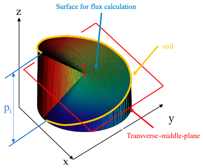
Figure 5 shows Schematic Diagram of the Specialized Numerical Integration Surface for Magnetic Flux Calculation of Variable-Pitch Coils.During the specific calculation process, the helical coil is first discretized into s infinitesimal segments along the trajectory of the wire. The current I i and the position vector r si for the i -th segment are strictly determined by the parametric equations of the helical tube. Subsequently, the Biot-Savart law is employed to calculate the axial magnetic flux density, B z , generated by all infinitesimal segments at an arbitrary point P x p , y p , z p in space. For point P, the total magnetic field is obtained through the superposition of the fields produced by all s discrete coil segments, expressed as:
B z = i = 1 s B z s i ,
where B z s i denotes the z-component of the magnetic field generated by the i-th current element at point P.
To accurately capture the magnetic flux generated by sparse or geometrically irregular coils, the conventional “transverse mid-plane” approximation is inadequate, as it fails to account for the strong magnetic field regions in the immediate vicinity of the wire under large pitch conditions. To address this, a specialized surface connecting the coil loop to its central axis is defined. For the k -th turn of the coil, this surface is constructed by connecting the physical trajectory of the coil to its corresponding projected points along the central axis. For a variable-pitch cylindrical solenoid, the z-coordinate, z 1 , of an arbitrary point P 1 x 1 , y 1 on this defined surface is calculated via linear interpolation based on its polar angle and the corresponding z-coordinate on the wire.
By discretizing the constructed surface for the k -th turn into a mesh grid, the single-turn magnetic flux ϕ k is obtained through the numerical integration of the axial magnetic field B z over this surface:
ϕ k = S k B z d S ( B z k Δ A 2 ) .
Next, the equivalent single-turn inductance of the k-th turn, L k , is calculated utilizing the current, i c k , flowing through the central infinitesimal element of that specific turn, with the relationship:
L k = ϕ k i c k .
By summing the equivalent inductances of all N individual turns, the total external inductance of the solenoid, L e x t , is derived ( L e x t = k = 1 N L k ). Finally, the overall inductance L is defined as the sum of the internal inductance and the external inductance, calculated using the formula:
L = L i n t + L e x t .

4.2.4. Calculation Model for Mutual Inductance ( M )

The method for calculating mutual inductance is very similar to the numerical integration method used in Section 4.2.3 to calculate external self-inductance. It will not be repeated here.
In the Domino system, it is necessary to comprehensively compute the mutual inductance effects between all adjacent and cross-interval coils to construct the complete system inductance matrix M . This matrix directly serves as the input parameter for the KVL circuit equation system described in Section 3.2:
M = L 1 M 12 M 1 n M 21 L 2 M 2 n M n 1 M n 2 L n .

4.3. Calculation of Internal Resistance in Variable Pitch Helical Pipes

The resistance of the coil is highly dependent on the operating frequency. Due to the skin effect, the coil resistance increases as the operating frequency increases. There exists a critical cutoff frequency, denoted as f c , below which the skin effect can be considered negligible. This cutoff frequency is calculated utilizing the formula provided in [20]:
f c = 4 π μ σ r w 2 ,
where μ and σ represent the magnetic permeability and electrical conductivity of the coil material, respectively. The resistance per unit length of the coil can be evaluated using the equation detailed in [20]:
r = 1 σ π r w 2 , f f c , 1 σ π r w 2 ( r w δ ) 2 , f > f c ,     ( Ω / m )
where δ = ρ / ( π f μ ) denotes the skin depth of the conductor, and ρ denotes the electrical resistivity of the wire material.

4.4. Simulation Validation of Computational Models

To validate the accuracy of the proposed model, results are compared against those from full-wave electromagnetic simulation.
To quantitatively evaluate the degree of non-uniformity of the variable-pitch coil, the mean value p ¯ and standard deviation σ p of the pitch p i for each turn are defined as follows:
p ¯ = 1 N i = 1 N p i ,
σ p = 1 N 1 i = 1 N ( p i p ¯ ) 2 .
Based on these parameters, the coefficient of variation in the pitch, denoted as C V p , is introduced as a dimensionless metric to quantify the degree of pitch variation:
C V p = σ p p ¯ .
Let L c a l denote the self-inductance calculated by the proposed model, and let L s i m denote the corresponding value obtained from simulation. The relative error rate for the self-inductance ( δ L ) is defined as follows:
δ L = L c a l L s i m L s i m × 100 % .
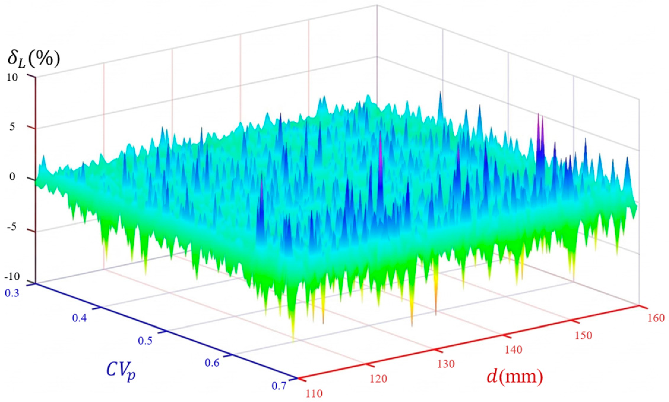
Let d represent the transmission distance between two adjacent coils. Through comprehensive simulations, heat maps illustrating the distribution of the relative error rates δ L within the parameter space of C V p , d can be plotted (as shown in Figure 6). By performing independent surface integration for each individual turn, this theoretical calculation method effectively addresses the issue of uneven magnetic field distribution caused by drastic variations in the pitch p i . The simulation validation demonstrates that the error rates of the proposed analytical model in calculating both the self-inductance and mutual inductance of variable-pitch coils are consistently maintained below 5%.
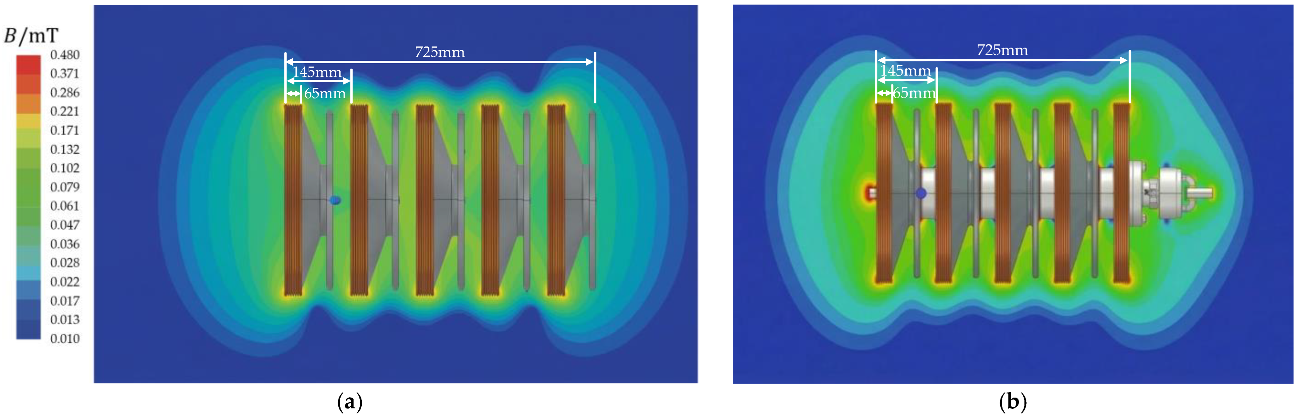
It is worth noting that in a practical insulator string environment, the presence of metallic hardware (e.g., iron caps and steel legs) induces high-frequency eddy currents and a slight inductance shift, potentially leading to a decrease in overall transmission efficiency. However, comprehensive electromagnetic simulations (Figure 7) confirm that these fittings do not significantly alter the primary magnetic field distribution. Since hardware-induced loss is not the primary focus of this study, the subsequent optimization model isolates the coil geometry as the core variable, leaving the electro-thermal co-simulation with hardware fittings for subsequent research.
To ensure computational feasibility during the multi-objective optimization process, two key assumptions were adopted. First, the model assumes the dominance of the axial magnetic field to streamline the numerical integration of the external inductance. While this represents an idealization of the fringing effects, the localized error is well-compensated, as evidenced by the <5% overall parameter accuracy confirmed through 3D FEM analysis. Second, the current analytical model does not explicitly calculate hardware-induced eddy current losses. It must be acknowledged that in actual 66 kV field deployments, the intersection of the high-frequency alternating magnetic field with the metallic components of the insulator string will inevitably generate eddy currents and parasitic thermal losses. Based on supplementary 3D electromagnetic co-simulations incorporating realistic material properties, these metallic components are projected to cause a 5% to 10% degradation in the overall system transmission efficiency. This provides a transparent baseline for future practical engineering deployments.

5. Multi-Objective Optimization Design Based on NSGA-II

The core contribution of our multi-objective framework is the integration of this specialized, non-uniform electromagnetic model into an NSGA-II algorithm. This integration is uniquely tailored to resolve the intricate trade-offs between transmission efficiency and output capacity, specifically operating under the unyielding spatial boundaries and high-voltage insulation constraints inherent to 66 kV domino insulator strings.

5.1. Mathematical Description of the Optimization Problem

The core of the optimization problem is to determine the optimal balance between transmission efficiency and output power by adjusting the pitch distribution of each coil turn and the system operating frequency, under the premise of satisfying the spatial structural constraints of the insulator and electrical insulation requirements. This constitutes a typical Constrained Multi-objective Optimization Problem (CMOP). The core novelty of this paper lies in the integration of this non-uniform electromagnetic model into the NSGA-II multi-objective framework, which is specifically tailored to balance transmission efficiency and output power under the unique spatial and insulation constraints of high-voltage domino insulator strings. The mathematical model is described as follows.

5.1.1. Decision Variables

To achieve a refined design of the non-uniform solenoid, this section designates both the coil geometry and the system operating frequency as decision variables.
As delineated in Section 4.1.3, to ensure that the total axial length of the coil strictly matches the spacing of the insulator sheds, the geometric variables are represented by a dimensionless weight vector x = x 1 ,   x 2 ,   ,   x N (where x i 0 , 100 , and the number of turns per coil N   =   10 ). The actual physical pitch p i is mapped and calculated using Equation (10).
Furthermore, the system operating frequency f directly influences the high-frequency internal resistance and the magnetic coupling characteristics of the coil. To match the optimal operating region of the GaN switching devices, the frequency range is constrained to f 150 , 300   kHz .
In summary, the comprehensive decision variable vector X of the system is defined as:
X = [ x 1 , x 2 , , x N , f ] T .

5.1.2. Objective Functions

This study establishes two conflicting optimization objectives: maximizing the system transmission efficiency η and maximizing the load output power P o u t .
Based on the KVL matrix equations detailed in Section 3, the loop currents Ii (i = 1, 2, …, n, where n is the total number of resonant loops in the system) are obtained, and the objective functions are defined as follows:
Transmission Efficiency Objective:
f 1 ( X ) = η ( X ) = I n 2 R L i = 1 n I i 2 R i ( X ) + I n 2 R L .
Output Power Objective:
f 2 ( X ) = P o u t ( X ) = I n 2 R L .
To accommodate the computational framework of multi-objective optimization algorithms, which inherently seek minimum values, the aforementioned maximization objectives are transformed into a minimization problem. The total objective function vector F X is defined as:
min F ( X ) = [ f 1 ( X ) , f 2 ( X ) ] T .

5.1.3. Constraints

Based on the physical limitations defined in Section 4.1.4, the optimization process must strictly satisfy specific geometric and electrical constraints. The geometric inequality constraints define the permissible boundaries for the variable pitch p i X . First, a minimum pitch limit is established to prevent short circuits and accommodate the necessary insulation layer:
g 1 , i ( X ) : D w i r e p i ( X ) 0 . ( i = 1 , , N )
Second, a maximum pitch limit is imposed to ensure the continuity and effectiveness of the magnetic coupling across the coil structure:
g 2 , i ( X ) : p i ( X ) h 2 0 . ( i = 1 , , N )
Beyond these geometric limitations, the optimization must also satisfy electrical equality constraints to guarantee optimal power transfer. The system is required to operate in a state of full resonance at all times. Therefore, for each candidate solution in each generation of the algorithm, the compensation capacitor C k must be dynamically matched according to its corresponding equivalent inductance L k X and the system frequency f :
h k ( X ) : 2 π f L k ( X ) 1 2 π f C k = 0 . ( k = 1 , , n )

5.2. Implementation of the NSGA-II Algorithm and Optimal Solution Decision-Making

To resolve the conflicting optimization objectives of “transmission efficiency” and “output power” in the design of the variable-pitch Domino coil, this paper employs NSGA-II for system-level parameter optimization. This algorithm generates a Pareto-optimal solution set in a single run, thereby providing a range of trade-off solutions for engineering design.

5.2.1. Implementation of the NSGA-II Algorithm

NSGA-II was selected over alternative optimization approaches for the following reasons. Brute-force parameter sweeps are computationally infeasible: with N + 1 = 11 de-cision variables discretized at 10 levels each, 1011 objective evaluations would be re-quired—a reduction in more than seven orders of magnitude compared to the 5000 eval-uations (50 × 100) used by NSGA-II. Gradient-based multi-objective methods are inappli-cable because Pareto dominance is not a differentiable relation, and the hard geometric constraints introduce non-smooth feasibility boundaries. A numerical comparison be-tween NSGA-II and Multi-Objective Particle Swarm Optimization (MOPSO) under identi-cal computational budgets (5000 function evaluations, averaged over 10 independent runs) confirms that NSGA-II consistently achieves a notably higher hypervolume indica-tor than MOPSO. This advantage is attributed to NSGA-II’s crowding distance sorting mechanism, which explicitly promotes Pareto front diversity—a critical property for providing engineers with a well-distributed range of efficiency–power trade-off solutions. Furthermore, NSGA-II’s elitism guarantee ensures that the best non-dominated solutions discovered in any generation are preserved in subsequent iterations, enabling reliable convergence in this constrained, non-convex design space.
Based on the Python 3.10.0, pymoo 0.6.0 optimization framework, the specific parameter settings of the algorithm are configured as follows: the population size is set to 50, the maximum number of iterations is 100, the crossover probability is 0.9, and the mutation probability is 0.1. The specific parameters for the NSGA-II algorithm were systematically determined through a pre-optimization convergence analysis rather than arbitrary selection. A population size of 50 was chosen to maintain sufficient genetic diversity, ensuring comprehensive exploration of the optimal solution space bounded by the strict spatial limits of the insulator, while simultaneously preventing the computational explosion associated with the complex numerical integration of the inductance matrix. Furthermore, iterative observations indicated that the Pareto front typically achieves a stable, non-dominated state after approximately 70 to 80 iterations. Consequently, defining the maximum iterations as 100 serves as a conservative threshold to guarantee reliable algorithmic convergence while optimizing computational efficiency.
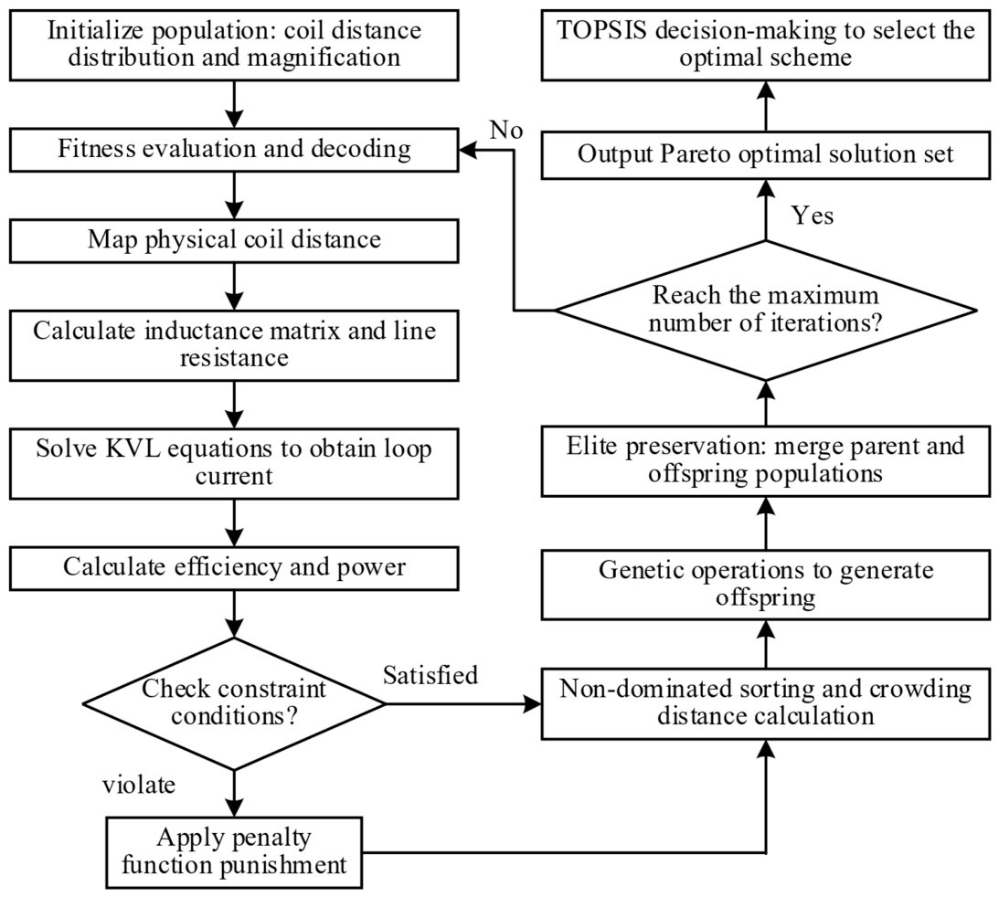
The algorithm adopts real-valued encoding. Each individual is represented by a floating-point vector of length N + 1 , corresponding to the geometric weight vector x and the frequency f defined in Section 5.1. Figure 8 shows Multi-objective optimization framework for variable-pitch domino WPT coils.

5.2.2. Fitness Evaluation Function

Fitness evaluation serves as the key interface between the optimization algorithm and the physical electromagnetic model. For each individual within the population, the fitness calculation follows a systematic physical procedure. Initially, the dimensionless variable x is decoded and mapped to the actual physical pitch p i to reconstruct the three-dimensional geometry of the variable-pitch coil. Following this reconstruction, the numerical integration model described in Section 4 is invoked. This step precisely calculates the self-inductance L i , the mutual inductance matrix M , and the high-frequency AC internal resistance R i under this specific geometric configuration.
Subsequently, the model verifies whether the reconstructed pitch satisfies the established geometric constraints, including the maximum pitch boundaries and the wire diameter limit D w i r e . If any constraints are violated, a penalty function method is applied, assigning an excessively large fitness penalty to the individual to ensure its elimination during the subsequent non-dominated sorting process. For valid configurations, the calculated electromagnetic parameters are then substituted into the system’s Kirchhoff’s Voltage Law (KVL) equations to solve for the resonant current distribution in each loop. Finally, the system’s transmission efficiency η and output power P o u t are calculated and returned to the algorithm as the two fitness objective values for that individual.

5.2.3. Optimal Solution Decision-Making Based on the TOPSIS Method

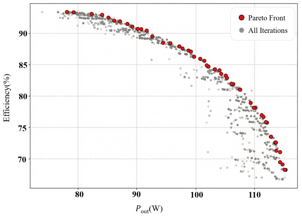
After the iterative evolution of the NSGA-II algorithm, the system outputs a Pareto optimal set comprising m non-dominated solutions as shown in Figure 9.
To avoid subjective biases and scientifically balance the conflicting objectives of “transmission efficiency” and “output power,” this paper employs the TOPSIS (Technique for Order Preference by Similarity to Ideal Solutions) method to comprehensively evaluate the Pareto set and select the optimal engineering solution. In the decision-making phase, an equal weighting scheme (0.5 for efficiency, w1, and 0.5 for output power, w2) was adopted as the baseline evaluation standard. This configuration mathematically models a monitoring device that requires a strict balance, representing typical equipment with moderate operational power consumption but restricted heat dissipation capabilities. With equal weights of 0.5 assigned to efficiency and power, Table 1 presents the relevant parameters of the optimal engineering solution. Ci refers to the TOPSIS proximity score.
As shown in Table 1, the proposed TOPSIS framework is highly adaptable and these weights can be dynamically adjusted based on specific field application profiles. For instance, when the target load consists of power-hungry devices like continuous pan-tilt surveillance cameras, the weighting matrix should be biased towards output capacity (e.g., w1 = 0.3, w2 = 0.7). Conversely, for micro-power devices, where preventing thermal accumulation inside the enclosed high-voltage insulator is the absolute priority, the decision matrix should heavily favor transmission efficiency (e.g., w1 = 0.7, w2 = 0.3) to minimize parasitic heat generation.

6. Experimental Validation and Characteristic Analysis Under Insulator String Environment

To validate the accuracy of the proposed variable-pitch solenoid model and the engineering feasibility of the NSGA-II/TOPSIS optimization scheme, a five-stage relay experimental prototype of the domino WPT system is constructed and subjected to comprehensive testing.

6.1. Experimental Prototype Construction and Parameter Configuration

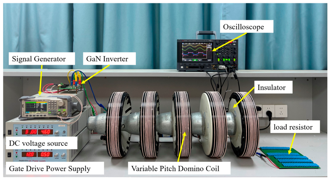
Based on the optimal engineering scheme (Solution 1) selected via the TOPSIS decision-making detailed in Section 5.2.3, a complete hardware experimental platform is constructed, as shown in Figure 10. The entire system comprises a DC stabilized power supply, a high-frequency full-bridge inverter circuit, in which GaN switches (RC65D110A, RealChip Semiconductor Co., Ltd., Shenzhen, China) were utilized to reduce high-frequency switching losses, a high-frequency signal generator, variable-pitch Domino coil groups, a resonant compensation capacitor array, and an equivalent load resistor.
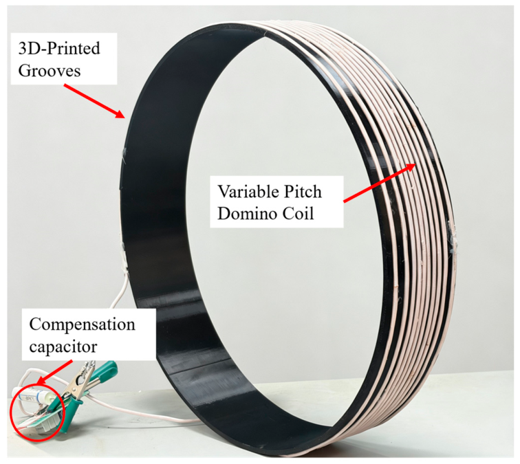
To accurately replicate the pitch weight vector X output by the optimization algorithm at the physical level, 3D printing technology is employed to customize the insulator shell framework with non-uniform helical grooves using photosensitive resin material, as shown in Figure 11. The enameled wire is embedded on the outer surface of the insulator strictly following the groove trajectory, thereby effectively minimizing geometric deformation errors caused by manual winding. The specific electrical parameters of the system and the selected nominal values of the resonant components are listed in Table 2. The operating frequency f = 231.75   kHz is the optimal frequency derived from the algorithm.

6.2. Experimental Results and Steady-State Waveform Analysis

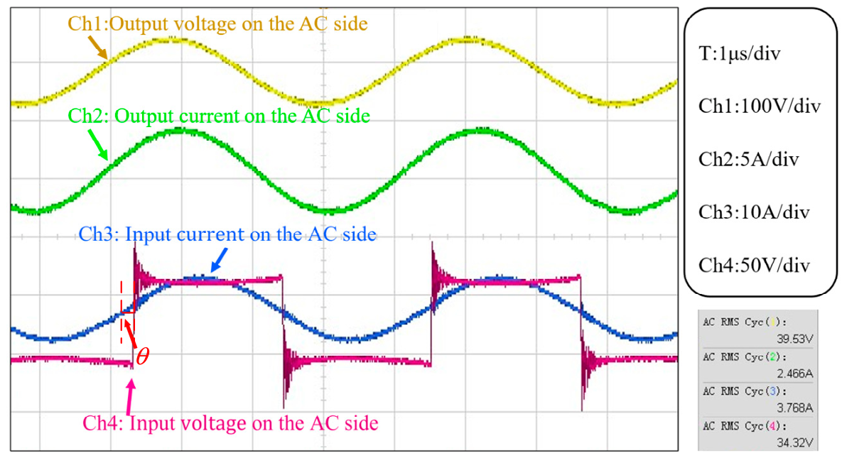
Full-load operation tests are conducted on the system under the conditions of an input DC voltage Ud = 35 V and a switching frequency locked at 2 31.75   kHz . Figure 12 shows the input and output voltage waveforms on the AC side. On the DC side, the input voltage is 34.32 V, the input current is 3.313 A, and the input power is 113.7 W. The output voltage is 39.53 V, the output current is 2.466 A, and the output power is 97.48 W. The overall efficiency of the unit reaches 85.73%.
The experimental waveforms show that the inverter output voltage is in phase with the transmitter current, indicating that the system achieves excellent zero-voltage switching (ZVS) characteristics under the set parameters and effectively suppresses reactive circulating currents. In Figure 12, θ represents the phase lag angle. ZVS operation is achieved by operating the GaN full-bridge inverter at a frequency slightly above the series resonance of the transmit-ter loop, so that the equivalent input impedance presented to the inverter is slightly induc-tive. This inductive loading causes the transmitter coil current to lag the inverter output voltage by a small phase angle. Before each GaN switch turns on, the body diode of the complementary switch in the same half-bridge conducts during the dead-time interval, clamping the drain-to-source voltage VDS to zero. The switch then turns on at zero drain-to-source voltage, completely eliminating the capacitive switching loss and sup-pressing high-frequency EMI at the 231.75 kHz operating frequency. Compared to the theoretical optimal solution generated by the NSGA-II algorithm (86.67% efficiency, 95.19 W power), the experimental efficiency and power errors were only 1.1% and 2.4%, respectively. This low error rate not only validates the accuracy and effectiveness of integrating the variable-pitch domino WPT coil model with the NSGA-II algorithm but also demonstrates that this analytical method can significantly reduce the time costs associated with traditional finite element simulations. Overall, this strategy not only improves the spatial magnetic field distribution and enhances equivalent mutual inductance but also successfully achieves a good balance between system power transmission and efficiency.
To establish a rigorous and convincing benchmark for evaluating the effectiveness of the proposed optimization framework, a comparative analysis was conducted against a standard configuration. Leveraging the validated analytical model developed in Section 4, a baseline system utilizing uniform, closely wound domino coils was mathematically evaluated.
To ensure strict fairness and analytical validity in the comparison, this uniform baseline was subjected to the exact same material and geometric constraints as the optimized variable-pitch system: it utilized the identical total length of Litz wire, the same wire diameter, and was strictly confined within the identical spatial boundaries defined by the 66 kV insulator sheds.
Table 3 presents the power transfer capabilities of the different systems evaluated under identical conditions (i.e., the same total Litz wire length, equivalent wire diameter, and strict confinement within the spatial limits of the 66 kV insulator sheds). The analytical comparison revealed a stark contrast in electromagnetic performance. Constrained by its fixed geometry, the uniform coil system failed to effectively distribute the magnetic flux across the crucial inter-stage coupling regions, resulting in a suboptimal mutual inductance matrix. Consequently, the uniform baseline system only achieved a calculated transmission efficiency of approximately 81.79% and an output power capability of 77.67 W. In contrast, the optimized variable-pitch configuration strategically redistributes the continuous pitch to actively shape the spatial magnetic field, successfully elevating the theoretical transmission efficiency to 85.7% and the output power to 97 W. This substantial, quantified improvement mathematically confirms that actively managing the non-uniform pitch distribution is a critical and highly effective strategy for maximizing WPT performance under strict high-voltage spatial constraints.
Table 4 compares the proposed system against five representative state-of-the-art domino WPT systems for high-voltage transmission line online monitoring equipment published between 2022 and 2024. The results demonstrate that this work achieves the highest output power (97.48 W) among all compared systems while maintaining a competitive transmission efficiency of 85.73%, and is the only design to employ NSGA-II dual-objective optimization under the strict geometric and insulation constraints of a 66 kV insulator string.
Directly isolating and measuring the static self-inductance and mutual inductance of the individual embedded coils using precision instruments presents significant mechanical and spatial alignment challenges within the fully assembled insulator string. In the proposed resonant WPT framework, the system’s operational resonant frequency and impedance matching network are intrinsically sensitive to variations in self-inductance. Simultaneously, the overall transmission efficiency and maximum output power are strictly bottlenecked by the mutual inductance between adjacent relay stages. If the absolute error of the analytically calculated parameters exceeded the simulated 5% margin, frequency detuning and drastic performance degradation would inevitably occur in the physical prototype. Consequently, the empirical realization under the designed operational frequency provides physical proof that the theoretical inductance parameters calculated by the proposed segmented current analysis model are highly accurate and reliable.

7. Conclusions

This paper addresses the challenge of power supply for high-voltage transmission tower monitoring equipment by proposing an optimization scheme for variable-pitch domino wireless power transfer coils based on insulator strings. By constructing a computational model of the electromagnetic parameters of non-uniform solenoids and combining the NSGA-II algorithm with TOPSIS decision-making, this study successfully resolves the inherent trade-off between maximizing transmission efficiency and maximizing output power. Experiments confirm that the optimized variable-pitch coil outperforms traditional uniformly wound designs in all key performance metrics, achieving a maximum transmission efficiency of 85.73% and a maximum output power of 97.48 W in a five-stage cascaded system. This study provides a reliable, efficient, and stable approach with significant engineering application value for contactless insulated power supply in complex high-voltage environments.
Nevertheless, several limitations of the current study should be acknowledged to guide future research. First, the number of turns per coil is fixed at N = 10 throughout the optimization; while this choice is justified by the insulator geometry constraints (see Section 4.1.3), treating N as a discrete decision variable in future work could potentially yield further performance gains. Second, hardware-induced eddy current losses from the metallic iron caps and steel legs of the insulator string are not incorporated into the NSGA-II fitness evaluation function; based on supplementary electromagnetic co-simulations, these components are expected to cause a 5–10% efficiency degradation in actual field deployments, and integrating a lightweight hardware loss surrogate model into the optimization loop is an important direction for future work. Third, the experimental prototype is limited to a five-stage relay chain, corresponding to a standard 66 kV insulator string; scaling to higher voltage classes (110 kV or 220 kV), requiring 7–15 cascading stages, will introduce more prominent non-adjacent cross-coupling effects, necessitating higher-order model complexity and increased optimization dimensionality. Fourth, the current model assumes constant wire resistivity at a nominal temperature; in enclosed insulator environments subject to thermal accumulation under continuous full-load operation, the increase in winding resistance could further reduce efficiency, motivating future thermal-electromagnetic co-optimization work.
Beyond the validated 66 kV application, the scalability of the proposed domino WPT framework to ultra-high-voltage networks, such as 110 kV or 220 kV, warrants further discussion. Scaling to these voltage levels typically necessitates an increase in the number of relay stages to approximately 7–15. A primary technical challenge in such extended chains is the exponential decay of overall transmission efficiency, driven by the accumulation of parasitic resistances and enhanced leakage flux across multiple air gaps. To address this issue, future research will focus on expanding the NSGA-II optimization to a higher-dimensional variable space to actively leverage or suppress cross-coupling between non-adjacent coils.


Author Contributions

Conceptualization, Y.X. and D.Z.; methodology, J.C.; software, D.Z.; validation, J.C., Y.X. and D.Z.; formal analysis, Y.X.; writing—original draft preparation, D.Z. and S.Z.; writing—review and editing, J.C. and Y.X.; visualization, J.C., D.Z. and S.L.; supervision, D.Z., J.C. and Y.X.; project administration, D.Z., H.M., M.A.V., C.W. and W.H.; funding acquisition, C.R. All authors have read and agreed to the published version of the manuscript.

Funding

This work was supported by “the Fundamental Research Funds for the Central Universities” (No. JS250008).

Institutional Review Board Statement

Not applicable.

Informed Consent Statement

Not applicable.

Data Availability Statement

The original contributions presented in the study are included in the article; further inquiries can be directed to the corresponding author.

Conflicts of Interest

The authors declare no conflicts of interest.

Abbreviations

The following abbreviations are used in this manuscript:
WPTWireless Power Transfer
NSGA-IIElitist Non-dominated Sorting Genetic Algorithm
CTCurrent Transformer
GaNGallium Nitride
RMSRoot Mean Square
TOPSISTechnique for Order Preference by Similarity to Ideal Solution
PCBPrinted Circuit Board
AC/DCAlternating Current/Direct Current
CMOPConstrained Multi-objective Optimization Problem

References

  1. Guo, B.; Li, Q.; Jiang, W.; Lu, K.; Cheng, H. A deep sensing system for monitoring the health status of transmission line equipment based on self-powered sensors. IEEE Sens. J. 2023, 23, 20834–20844. [Google Scholar] [CrossRef] [Scilit]
  2. Zhou, J.; Li, Z.; Lee, C.K.; Chan, K.W.; Hui, S.Y.R. A weather-independent and renewable power supply with wireless power transfer feature for powering online monitoring systems in smart grid. IEEE Trans. Ind. Electron. 2023, 70, 6414–6424. [Google Scholar] [CrossRef] [Scilit]
  3. Riba, J.-R.; Moreno-Eguilaz, M.; Bogarra, S. Energy harvesting methods for transmission lines: A comprehensive review. Appl. Sci. 2022, 12, 10699. [Google Scholar] [CrossRef] [Scilit]
  4. Qu, J.; He, L.; Tang, N.; Lee, C.K. Wireless power transfer using domino-resonator for 110-kV power grid online monitoring equipment. IEEE Trans. Power Electron. 2020, 35, 11380–11390. [Google Scholar] [CrossRef] [Scilit]
  5. Wang, K.; Liang, R.; Yang, Y. A load-independent self-oscillating control of domino wireless power transfer systems for high-voltage power grid monitoring equipment. Energies 2022, 15, 4228. [Google Scholar] [CrossRef] [Scilit]
  6. Rong, C.; Chen, M.; Wang, Q.; Yan, L.; Guo, Y.; Gao, H.; Wang, H.; Liu, X. Optimization Design of Hybrid Resonance-Based Passive Shielding Coils for Low-Electromagnetic Field Leakage and High Efficiency in WPT System. IEEE Trans. Ind. Electron. 2025, 7, 8757–8767. [Google Scholar] [CrossRef] [Scilit]
  7. Rong, C.; Wang, H.; Gao, H.; Cai, W.; Han, W.; Zhang, X.; Jie, H.; Aime, L.-E.; Xu, Y.; Zhao, Z. Magnetically coupled resonant wireless power transfer for internet of things perception layer: A review. Renew. Sustain. Energy Rev. 2025, 223, 116013. [Google Scholar] [CrossRef] [Scilit]
  8. Rong, C.; Duan, X.; Chen, M.; Wang, Q.; Yan, L.; Wang, H.; Xia, C.; He, X.; Zeng, Y.; Liao, Z. Critical Review of Recent Development of Wireless Power Transfer Technology for Unmanned Aerial Vehicles. IEEE Access 2023, 11, 132982–133003. [Google Scholar] [CrossRef] [Scilit]
  9. Wu, Z.; Tan, L.; Xu, H.; Shen, S.; Huang, X. Design of the long-distance wireless power transfer system with multiple relay coils based on loss optimization. Electr. Eng. 2024, 106, 3337–3348. [Google Scholar] [CrossRef] [Scilit]
  10. Cai, C.; Wang, J.; Liu, R.; Fang, Z.; Zhang, P.; Long, M.; Hu, M.; Lin, Z. Resonant wireless charging system design for 110-kV high voltage transmission line monitoring equipment. IEEE Trans. Ind. Electron. 2019, 66, 4118–4129. [Google Scholar] [CrossRef] [Scilit]
  11. Fang, Y.; Qu, J.; Pong, B.M.H.; Lee, C.K.; Hui, R.S.Y. Quasi-static modeling and optimization of two-layer PCB resonators in wireless power transfer systems for 110-kV power grid online monitoring equipment. IEEE Trans. Ind. Electron. 2022, 69, 1400–1410. [Google Scholar] [CrossRef] [Scilit]
  12. Li, Y.; Gui, L.; Jiang, Y.; Jing, R.; Li, Y.; He, Z. Optimal configuration of single-layer domino-coils with uniform spacing for online monitoring equipment in smart grid. IEEE Trans. Power Electron. 2024, 39, 14307–14317. [Google Scholar] [CrossRef] [Scilit]
  13. Yazdi, S.S.H.; Shafiei, S.; Kapanov, A.; Shakhin, Y.; Namadmalan, A.; Bagheri, M. Enhanced domino wireless power transfer for transmission line monitoring: Overcoming external metal object interference and optimizing coil design. IEEE Trans. Power Deliv. 2024, 39, 1137–1150. [Google Scholar] [CrossRef] [Scilit]
  14. Hui, S.Y.R.; Zhong, W.; Lee, C.K. A critical review of recent progress in mid-range wireless power transfer. IEEE Trans. Power Electron. 2014, 29, 4500–4511. [Google Scholar] [CrossRef] [Scilit]
  15. Kim, J.; Park, Y.-J. Approximate closed-form formula for calculating ohmic resistance in coils of parallel round wires with unequal pitches. IEEE Trans. Ind. Electron. 2015, 62, 3482–3489. [Google Scholar]
  16. Paul, C.R. Inductance: Loop and Partial; John Wiley & Sons: New York, NY, USA, 2010. [Google Scholar]
  17. Yan, Z.; Xie, H.; Li, Y.; He, Z.; Yang, H.; Zhou, W.; Zhu, C.; Jing, X.; Chen, S.; Mai, R. A monitoring equipment charging system for HVTL based on domino-resonator WPT with constant current or constant voltage output. IEEE Trans. Power Electron. 2022, 37, 3668–3680. [Google Scholar] [CrossRef] [Scilit]
  18. Deb, K.; Pratap, A.; Agarwal, S.; Meyarivan, T. A fast and elitist multiobjective genetic algorithm: NSGA-II. IEEE Trans. Evol. Comput. 2002, 6, 182–197. [Google Scholar] [CrossRef] [Scilit]
  19. Zhang, W.; Wong, S.-C.; Tse, C.K.; Chen, Q. Design for efficiency optimization and voltage controllability of series-series compensated inductive power transfer systems. IEEE Trans. Power Electron. 2014, 29, 191–200. [Google Scholar] [CrossRef] [Scilit]
  20. Zhou, W.; Huang, S. An Accurate Model for Fast Calculating the Resonant Frequency of an Irregular Solenoid. IEEE Trans. Microw. Theory Tech. 2019, 67, 2663–2673. [Google Scholar] [CrossRef] [Scilit]
  21. Wang, W.; Duan, M.; Zeng, Z.; Liu, H.; Ji, Z. Research on optimal coil configuration scheme of insulator relay WPT system. Front. Electron. 2023, 4, 1034082. [Google Scholar] [CrossRef] [Scilit]
Figure 1. Structure of Wireless Power Supply System for Online Monitoring Devices of High-Voltage Transmission Towers.
Applsci 16 05241 g001
Figure 2. Equivalent Circuit of a Magnetically Coupled Domino Coil Wireless Power Transfer System.
Applsci 16 05241 g002
Figure 3. Schematic Diagram of Domino Resonant WPT System.
Applsci 16 05241 g003
Figure 4. Geometric Configuration and Key Parameters of Coils with Fixed Pitch p .
Applsci 16 05241 g004
Figure 5. Schematic Diagram of the Specialized Numerical Integration Surface for Magnetic Flux Calculation of Variable-Pitch Coils.
Applsci 16 05241 g005
Figure 6. Heat map of relative error rates ( δ L ) for inductance calculation across the parameter space of pitch variation coefficient ( C V p ) and transmission distance ( d ).
Applsci 16 05241 g006
Figure 7. Magnetic field distribution of an insulator string. (a) Without hardware. (b) With hardware.
Applsci 16 05241 g007
Figure 8. Multi-objective optimization framework for variable-pitch domino WPT coils.
Applsci 16 05241 g008
Figure 9. Pareto Front.
Applsci 16 05241 g009
Figure 10. Prototype of the system.
Applsci 16 05241 g010
Figure 11. Variable Pitch Domino Coil.
Applsci 16 05241 g011
Figure 12. Voltage and current waveforms on the ac side.
Applsci 16 05241 g012
Table 1. Comparison of Typical Optimal Solutions from the Pareto Front Based on TOPSIS Decision.
SchemeDecision BasisExpected η (%)Expected P out (W) C i
Solution 1Comprehensive Optimal (Selected)86.6795.190.8379
Solution 2Biased Towards Max Efficiency92.380.240.5208
Solution 3Biased Towards Max Power69.4119.330.5474
Table 2. Key Parameters of the Experimental Prototype.
ParameterValueParameterValue
L151.83 μHC19.11 nF
L251.78 μHC29.11 nF
L351.26 μHC39.20 nF
L451.80 μHC49.10 nF
L551.91 μHC59.09 nF
p111.5853 mmk120.16916
p23.9420 mmk130.05054
p36.3884 mmk140.01988
p44.6474 mmk150.00930
p53.6825 mmk230.16916
p63.7341 mmk240.05054
p74.1728 mmk250.01988
p85.4395 mmk340.16916
p910.5969 mmk350.05054
p1010.8112 mmk450.16916
R1~R50.18 ΩRL15 Ω
Ud35 Vf231.75 kHz
Table 3. Comparison of the power transfer capabilities between the uniform and non-uniform coil systems.
Coil ConfigurationsExpected η (%)Expected P out (W)f
Uniform multi-turn coil81.7977.67231.75 KHz
non-uniform multi-turn coil86.6795.19
Table 4. Performance Comparison with Domino WPT Systems for High-Voltage Transmission Line Online Monitoring Equipment.
Parameter[17] Yan et al.
2022
[11] Fang et al.
2022
[21] Wang et al.
2023
[13] Yazdi et al.
2024
[12] Li et al.
2024
This Work
Voltage class (kV)1101101106366
Number of relay stages4465 relay
(7 coils total)
5 stages
Transmission distance (m)1.101.141.0150.500.58
Output power Pout (W)30201.8112.2397.48
Transmission efficiency η (%)4660.1185.9485.73
Best reported η (%)4660.1185.9485.73
Optimization methodNoneSimulation
-driven
Parametric sweep,
position & turns
Numerical
metaheuristic
T-equivalent
analytical model
NSGA-II
multi-objective
Optimization objectivesN/AQ-factorEfficiencyMulti-objectiveEfficiencyPout and η
Disclaimer/Publisher’s Note: The statements, opinions and data contained in all publications are solely those of the individual author(s) and contributor(s) and not of MDPI and/or the editor(s). MDPI and/or the editor(s) disclaim responsibility for any injury to people or property resulting from any ideas, methods, instructions or products referred to in the content.