Article

Resilient End–Edge–Cloud Collaboration for Control Continuity and Closed-Loop Alarm Management in Solar Greenhouse IoT Systems Under Degraded Network Conditions

College of Engineering, Heilongjiang Bayi Agricultural University, Daqing 163319, China
*
Author to whom correspondence should be addressed.
Appl. Sci. 2026, 16(11), 5191; https://doi.org/10.3390/app16115191
Submission received: 28 April 2026 / Revised: 18 May 2026 / Accepted: 20 May 2026 / Published: 22 May 2026
(This article belongs to the Section Agricultural Science and Technology)

Abstract

Degraded network conditions and intermittent disconnections can impair solar greenhouse Internet of Things (IoT) systems by delaying cloud-to-field control, generating burst traffic after reconnection, and disrupting alarm feedback loops. This paper proposes a resilient end–edge–cloud collaborative framework for maintaining control continuity and closed-loop alarm reliability under unstable edge–cloud communication. The framework evaluates network quality using round-trip time, packet loss rate, and consecutive no-response duration, and combines hysteresis-based state switching, control leases, edge takeover, differential backfill, and locally persistent alarm-state synchronization. During disconnection, the edge gateway uses the latest valid configuration to execute fallback local control; after reconnection, high-priority events are uploaded first through a hierarchically rate-limited recovery strategy. In the scripted simulation experiments, the proposed method reduced peak backfill throughput from 2.16 ± 0.06 MB/s to 0.69 ± 0.01 MB/s, shortened high-priority event completion time from 17.3 ± 2.7 s to 2.0 ± 0.7 s, and increased the acknowledgment success rate at 20% packet loss from 76.5 ± 2.2% to 98.4 ± 0.8%. It also reduced the maximum temperature deviation during disconnection from 7.20 °C to 3.50 °C. These results suggest that the proposed framework can improve control continuity and alarm-loop completeness under the specified simulation settings. A supplementary trace-driven recovery evaluation using public 5G testbed measurements showed a similar qualitative trend. Broader validation with field-deployed greenhouse IoT platforms or hardware-in-the-loop testbeds is still needed.

1. Introduction

In recent years, agricultural Internet of Things (IoT) technologies have enabled solar greenhouses to shift from manual, experience-driven management to data-driven remote monitoring and actuation [1,2]. In practical deployments, however, greenhouse sites are often located in rural areas where cellular connectivity is unstable because of terrain shielding, limited base-station coverage, and weather disturbances. Consequently, the edge–cloud link may experience large latency variations, packet loss, bandwidth fluctuations, and intermittent disconnections.
Under a cloud-centric architecture, such communication impairments can delay cloud-to-field control delivery, destabilize data uploads, and interrupt alarm feedback loops. These failures may eventually lead to control drift, delayed responses to high-priority operational events, and poor traceability of alarm handling. Studies on cloud–edge–device collaboration in smart agriculture and IoT architectures have shown the potential of layered end–edge–cloud deployments [3,4]. Reviews of edge, cloud, and edge–fog–cloud collaboration have further clarified how multi-tier architectures can support distributed services under heterogeneous network conditions [5,6]. Research on data resilience in fog computing and robustness assessment of MQTT-based IoT systems has also provided useful insight into service continuity under communication disturbances [7,8]. In greenhouse control, robust model predictive control and data-driven climate-control methods have improved regulation performance under uncertain operating conditions [9,10]. Related studies on multi-point temperature management and solar greenhouse microenvironment modeling further show that actuator dynamics and microclimate disturbances can significantly influence regulation performance [11,12]. However, relatively few studies have examined these issues together in solar greenhouse IoT systems, especially when network-state evaluation, control handover, disconnected operation, recovery backfill, and alarm-loop state synchronization must be coordinated under degraded edge–cloud communication.
To bridge this gap, this study proposes a resilient end–edge–cloud collaborative mechanism for solar greenhouse IoT systems operating under degraded network conditions and intermittent disconnections. The proposed mechanism evaluates link quality using round-trip time (RTT), packet loss rate (PLR), and consecutive no-response duration; uses hysteresis to suppress unnecessary state-switching oscillations; and uses control leases to define clear control authority between the cloud and the edge gateway. During disconnection, the edge gateway uses the latest validated configuration to execute fallback local control. After reconnection, the system enters a recovery phase in which high-priority events are prioritized and differential backfill is rate-limited to support gradual synchronization.
The main contributions of this paper are as follows: (1) This study proposes an integrated control-continuity mechanism for degraded-network greenhouse IoT scenarios. The mechanism coordinates network-state evaluation, hysteresis-guided authority switching, control leases, edge takeover, and recovery-phase backfill. (2) An alarm lifecycle management mechanism is designed to support traceable delivery, acknowledgment, handling, and feedback through local persistence, differential retransmission, and idempotent state synchronization. (3) The proposed mechanism is evaluated through scripted degraded-network simulations, and the results show relative improvements over a cloud-centric baseline in control continuity, recovery-phase synchronization, and alarm-loop completion.
The remainder of this paper is organized as follows. Section 2 defines the system architecture and interaction requirements. Section 3 presents the collaborative control mechanism. Section 4 describes the alarm closed-loop mechanism and the simulation setup. Section 5 reports and discusses the experimental results. Section 6 concludes the paper.

2. System Architecture and Problem Requirements

2.1. Scenario Model and System Architecture

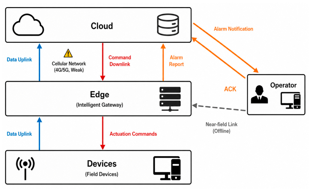
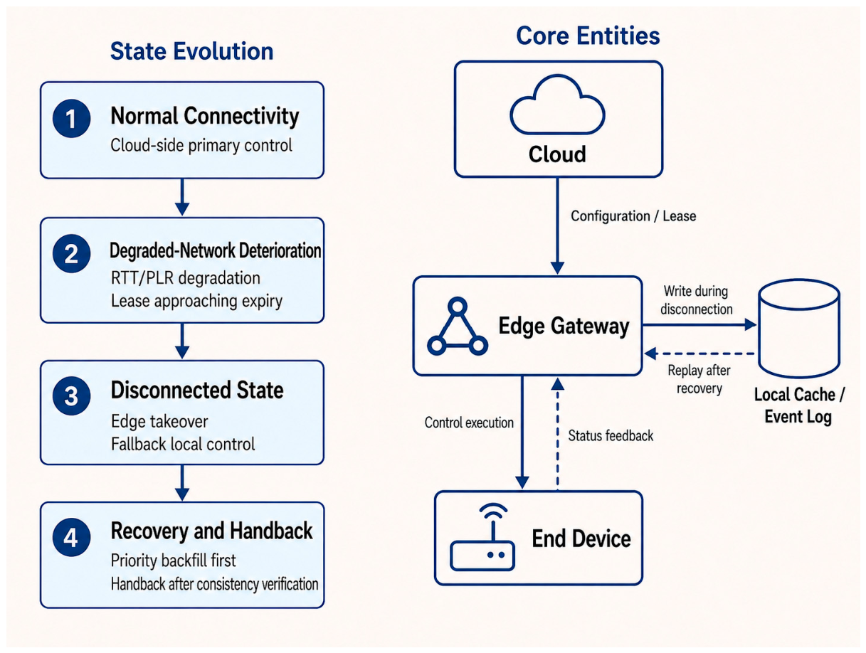
As shown in Figure 1, the target remote-monitoring system is modeled as a four-layer “end–edge–cloud–user” architecture. The model is used to describe data acquisition, control execution, and alarm handling when the edge–cloud link is degraded or intermittently disconnected. In this study, end-layer sensors and actuators are assumed to operate normally, while the edge gateway is assumed to provide basic local computing, buffering, and control-execution capabilities.
The end layer consists of environmental sensors, such as temperature, humidity, and light sensors, as well as actuators, such as curtain motors, vent motors, and heating equipment. It is mainly responsible for environmental data acquisition and actuation execution, with an emphasis on real-time sensing and reliable response, and it usually does not undertake complex strategy computation tasks.
The edge layer is centered on an on-site intelligent gateway located between the end layer and the cloud platform, and it is responsible for protocol adaptation, data aggregation, and local collaborative control. Under normal network conditions, the edge layer mainly performs data forwarding and status aggregation. Under degraded network conditions or disconnections, it must also undertake tasks such as network-state awareness, control takeover, local buffering, and recovery backfill, making it a key component for maintaining continuous system operation.
The cloud layer is deployed on remote servers and is mainly responsible for global strategy management, parameter and configuration delivery, historical data storage and analysis, and alarm-rule computation. The cloud layer has strong computing and storage capabilities, but its control and interaction performance depends to a large extent on the quality of the edge–cloud link. When the link is under degraded network conditions or disconnections, cloud-side control delivery and alarm interaction may suffer from latency accumulation, message loss, and state inconsistency.
The user layer refers to managers who participate in system operation, maintenance, and response decision-making through a mobile app or web interface. Their main tasks include receiving alarms, acknowledging alarm status, performing handling operations, and recording feedback. In this paper, ACK denotes an alarm-acknowledgment message, whereas handling feedback is treated as a separate but associated state update.
Within this architecture, the system mainly involves three types of interaction links. The first is the data uplink, through which environmental data and device status collected at the end layer are aggregated by the edge layer and uploaded to the cloud. The second is the control downlink, through which control parameters or configuration strategies generated by the cloud are forwarded by the edge layer to the end-layer actuators for execution. The third is the alarm closed-loop link, which covers the complete interaction process from alarm generation, reporting, and notification delivery to user acknowledgment, handling operations, and result feedback.
Among these links, degraded network conditions and disconnections mainly occur on the cellular edge–cloud link, directly affecting the timeliness of data uploads, the reachability of control delivery, and the completeness of alarm feedback. Accordingly, the edge layer is treated as more than a relay node in this study; it is responsible for local control continuity, buffered backfill, and state coordination when the edge–cloud link is degraded or disconnected. The above scenario model, therefore, provides a unified basis for the subsequent definition of degraded-network operating conditions, the design of the collaborative mechanism, and the analysis of alarm interaction [13,14]. Related studies on green fog computing and agricultural green productivity further suggest that the edge layer in agricultural IoT scenarios serves a role beyond simple forwarding [15,16]. Meanwhile, advances in edge artificial intelligence further support the feasibility of localized intelligence and rapid response on the agricultural field side [17].

2.2. Degraded Network Conditions and Interaction Requirements

To support the subsequent state-machine design, collaborative-control triggering, and simulation-based evaluation, this paper provides an operational definition of degraded network conditions. Because the key disturbances arise on the edge–cloud link, round-trip time (RTT), packet loss rate (PLR), and consecutive no-response duration are used as the indicators for network assessment. RTT characterizes interaction latency, PLR reflects transmission reliability, and consecutive no-response duration captures severe congestion or link interruption along the control path. The edge layer samples these indicators through periodic heartbeat messages and determines the current communication state accordingly. The thresholds adopted here are intended for mechanism triggering and simulation repeatability rather than as universal engineering standards for all greenhouse deployments.
Based on these indicators, communication quality is classified into three network states: online, degraded, and disconnected. When any indicator reaches the criterion for a worse state, the system is downgraded according to a worst-condition-first principle so that protective strategies are activated promptly. Recovery, by contrast, is modeled as an operational phase triggered after reconnection from the disconnected state rather than as a fourth network state. During recovery, upward transitions are constrained by the hysteresis mechanism described later. The corresponding thresholds are listed in Table 1.
Under degraded or disconnected conditions, the alarm path is more sensitive to timeliness and feedback completeness than ordinary monitoring-data links. In this paper, the alarm handling process is abstracted into four stages: discovery, acknowledgment, handling, and feedback synchronization. Two major failure points are identified. The first is a delivery failure point, where alarm notifications may be delayed, lost, or delivered out of order because of latency, packet loss, or link interruption, preventing users from receiving risk information promptly. The second is a feedback failure point, where an alarm may already have been acknowledged or handled, but the acknowledgment message and the handling record cannot be returned reliably, making it difficult to synchronize system states and potentially leading to redundant notifications or duplicate handling.
Based on the above analysis, four core requirements are identified for degraded-network scenarios: (1) Delivery reachability: high-priority alarms and important operational events generated during disconnection should be buffered locally and retransmitted according to priority after link recovery, thereby reducing the risk of missed alarm records. (2) Temporal distinguishability: the system should distinguish event occurrence time from arrival time and mark delayed information, thereby helping separate historical records from current information during recovery. (3) Interaction-load controllability: during recovery, the system should support alarm deduplication, aggregation, and prioritized presentation to reduce concentrated alarm records during backfill. (4) Closed-loop traceability: acknowledgment messages and handling records should support asynchronous synchronization, and state consistency should be restored after recovery so that alarms form a traceable closed loop from delivery to feedback.
These requirements correspond directly to the mechanism design presented in the following sections. Section 3 addresses control handover, edge takeover, and recovery backfill to maintain control continuity and state consistency. Section 4 focuses on alarm-event management, duplicate suppression, and acknowledgment synchronization to improve reliable alarm delivery and closed-loop tracking. Section 5 and Section 6 then describe the evaluation settings and the experimental analysis. Related greenhouse climate-control studies also indicate that local response capability can be useful when environmental conditions and device responses are uncertain [18,19].

3. Proposed End–Edge–Cloud Collaborative Control Mechanism

3.1. Network-State Determination and Control Authority Allocation

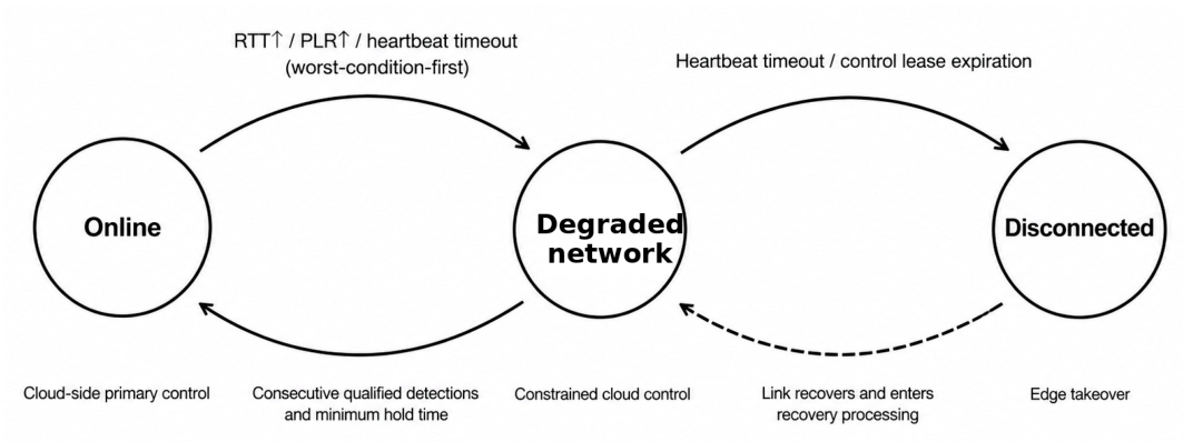
To support continuous system operation under degraded network conditions, this paper proposes a collaborative control mechanism based on network-state determination and dynamic control-authority allocation. The edge layer periodically acquires RTT, PLR, and consecutive no-response duration through heartbeat messages and determines the current network state accordingly. When any indicator satisfies the criterion for a worse state, the system is downgraded according to a worst-condition-first principle. When communication quality recovers, upward transitions are further constrained by a hysteresis mechanism to avoid frequent switching near threshold boundaries. The resulting network-state transition relationships are illustrated in Figure 2.
During recovery, immediately upgrading the state based on a single observation can easily lead to repeated state-switching oscillations under fluctuating, degraded network conditions, which may in turn disturb the control path. To address this issue, a hysteresis strategy is introduced for state upgrading. Specifically, when the network state improves from a lower level to a higher level, the system is allowed to switch to the better state only after the corresponding criteria are satisfied in multiple consecutive detections and maintained for a minimum duration [20]. This strategy does not alter the rapid downgrade principle under abnormal conditions, but it suppresses short-term switch-back behavior during recovery and improves the stability of control-authority switching.
To make the state-switching logic more explicit, the network-state determination procedure is summarized in Algorithm 1. The procedure formalizes the rule-based mechanism described above: downgrading follows a worst-condition-first principle, whereas upward transitions are constrained by hysteresis. The recovery phase is not treated as an independent network state in this study; instead, it is triggered after reconnection from the disconnected state and is used for backfill and consistency verification.
Algorithm 1. Network-state determination and hysteresis-based switching.
Input: RTT, PLR, consecutive no-response duration, current communication state S(t), and recent observations used for the hysteresis check.
Output: Updated communication state S(t + 1).
1. Sample RTT, PLR, and consecutive no-response duration through heartbeat messages.
2. Determine the candidate state S_c according to the thresholds in Table 1:
    2.1. If any indicator satisfies the disconnected condition, set S_c = disconnected.
    2.2. Else if any indicator satisfies the degraded condition, set S_c = degraded.
    2.3. Else set S_c = online.
3. If S_c is worse than the current state S(t), immediately downgrade S(t + 1) to S_c.
4. If S_c is better than S(t), check whether the better state has been observed continuously and maintained for the required minimum duration.
5. If the hysteresis condition is satisfied, update S(t + 1) to S_c; otherwise, keep S(t + 1) = S(t).
6. If the system changes from disconnected to degraded or online, enter the recovery phase before normal cloud-side primary control is restored.
7. During the recovery phase, prioritize event backfill and cloud–edge consistency verification before control authority is handed back to the cloud.
Algorithm 1 is a rule-based description of the state-switching logic used in the simulation. It does not introduce a new deployment-level network diagnosis algorithm. The thresholds are used to trigger mechanism switching and to keep the simulation repeatable, rather than to define universal engineering standards for greenhouse deployments.
For control-authority allocation, the system adopts a collaborative mode of “cloud-side primary control with edge-side execution” [21]. In the online state, the cloud is responsible for major strategy generation and parameter dispatch, whereas the edge layer handles on-site execution and state feedback. Under degraded network conditions, the cloud remains dominant, but the issued content mainly consists of configuration-related parameters, such as target temperatures, control periods, and strategy thresholds. After receiving these parameters, the edge layer performs freshness and duplicate checks and applies only those commands that are valid and non-duplicated, thereby reducing the adverse effects of command loss, out-of-order delivery, or repeated execution under degraded network conditions.
To further reduce the risk of conflicts caused by concurrent cloud–edge control, a control lease mechanism is introduced [22,23]. Cloud-issued control commands or configuration parameters are associated with a validity period, and the edge layer accepts and executes cloud control only while the lease remains valid. Once the lease expires or once the network enters the disconnected state, control authority automatically shifts to the edge layer, which then takes over control execution and enters a local fallback mode. The purpose of the control lease is not to replace cloud control, but to provide a clear boundary for control authority under degraded and disconnected conditions, thereby preventing conflicts caused by simultaneous control of the same actuator by the cloud and edge layers.
When the edge–cloud link recovers from the disconnected state to the degraded or online state, control authority is not immediately returned to the cloud. Instead, the system first enters a recovery phase. In this phase, the edge layer prioritizes reporting high-priority events and summaries of control actions generated during the disconnection period, and then gradually completes cloud–edge state alignment through consistency verification. Only after both sides are confirmed to be largely consistent does the system return to the normal collaborative mode of “cloud-side primary control with edge-side execution”.
To clarify the control-lease lifecycle and the edge-takeover triggering logic, the rule-based handover process is summarized in Table 2. The table does not define a full distributed lease protocol; rather, it describes how the control authority is bound and switched in the proposed simulation-based mechanism.
In this table, lease renewal or update refers to the reception of a newer, valid configuration or command before the previous lease expires. The handback step is performed only after recovery backfill and state verification, so that outdated cloud commands do not immediately override edge-side actions generated during disconnection.
Based on the above state-switching and lease-handover rules, the proposed mechanism reduces unnecessary authority switching under degraded-network scenarios and provides the basis for the subsequent edge takeover and recovery-backfill mechanisms.

3.2. Disconnection Fault Tolerance: Edge Takeover and Local Buffering

When the edge–cloud link enters the disconnected state, the control objective shifts from cloud-assisted optimization to stable and continuous on-site operation. To prevent control interruption or loss of actuator supervision when the cloud becomes unreachable, an edge-takeover mechanism is adopted for disconnection scenarios. Once the network state is identified as disconnected and the cloud control lease expires, the edge gateway takes over control based on the most recent valid configuration to maintain field operation. Meanwhile, the edge layer buffers operational data and high-priority events locally to support differential backfill and consistency verification after link recovery, as illustrated in Figure 3.
Edge takeover does not imply that the edge layer reconstructs a complete global control strategy. Instead, it performs fallback local control based on the existing configuration. Specifically, the edge layer continues to use the key control parameters most recently issued by the cloud and already in effect, such as target temperatures, control periods, and relevant strategy thresholds. When sensor-data timeouts occur, environmental indicators remain outside acceptable bounds, or actuator operation becomes abnormal, the system triggers conservative local control rules and applies conservative control actions to key actuators in order to reduce operational risk during disconnection. The purpose of this design is to preserve basic system controllability as far as possible when the cloud is unavailable, rather than to continue pursuing complex optimization objectives.
During disconnection, fallback local control is implemented as a set of conservative rules based on the latest valid configuration. These rules specify when the edge gateway should keep, limit, or defer local control actions under sensor-data delay, environmental deviation, actuator abnormality, or alarm generation. The main triggering conditions and corresponding local actions are summarized in Table 3.
These rules are intended to bound local actions during the simulated disconnection window and to preserve the information required for recovery. In practical greenhouse deployments, acceptable ranges, data validity windows, actuator limits, and abnormality conditions should be calibrated according to crop requirements, device characteristics, and site-specific operational constraints.
To support information retention during disconnection and subsequent recovery, the edge layer also maintains a local buffering mechanism, in which the stored content mainly includes two categories: operational data and event logs [24,25]. The operational data buffer stores environmental time-series data and actuator-state information and can be organized using a fixed-length queue or a circular buffer. Data are written in chronological order within a limited storage space so as to control local storage overhead. Event logs record key control actions and alarm events generated during disconnection, including occurrence time, event source, parameter information, and execution results, thereby providing the basis for subsequent state alignment and differential backfill.
Given the limited buffer space available during disconnection, the proposed mechanism distinguishes between general operational data and high-priority event records. The former mainly supports historical retransmission and state reconstruction during recovery and may therefore be overwritten or compressed under storage constraints. The latter is directly related to control execution and alarm closed-loop management and should therefore be retained with higher priority to avoid being displaced by ordinary data during disconnection. Through this hierarchical buffering strategy, the edge layer retains the information most relevant to subsequent recovery while limiting the amount of low-priority data stored locally.
Therefore, edge takeover and local buffering together provide the basic fault-tolerance support for disconnection scenarios. The former maintains continuity of on-site control, whereas the latter preserves the key data and event records required during recovery. Working together, they allow the system to retain basic controllability and recoverability while the edge–cloud link is temporarily unavailable, and they establish the foundation for subsequent differential backfill and state alignment.

3.3. Recovery After Reconnection: Data Backfill and Consistency Alignment

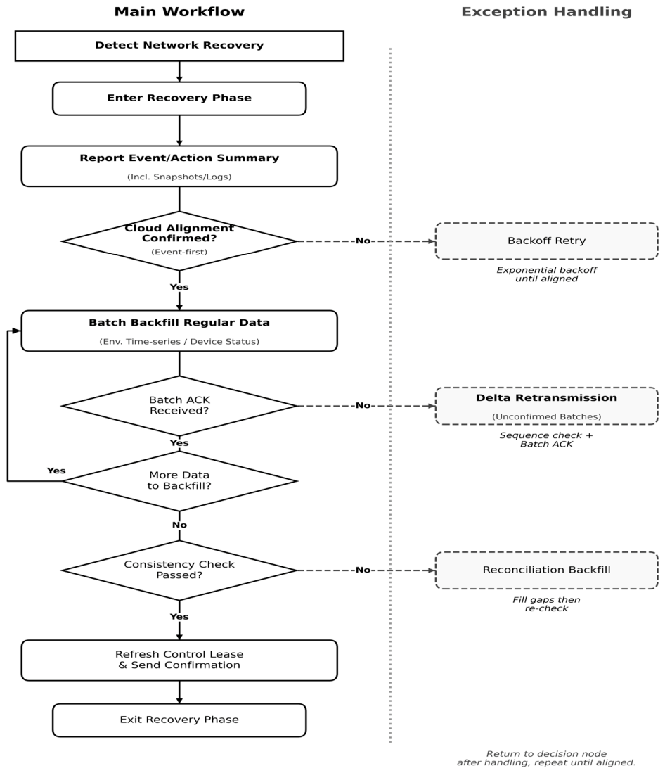
When the edge–cloud link recovers from the disconnected state to a degraded or online state, the system enters a recovery phase. At this point, the focus is no longer merely to restore communication, but to achieve cloud–edge state alignment under limited bandwidth and to backfill the data and event records buffered at the edge layer during disconnection in an orderly manner. If all buffered content is uploaded immediately after recovery, burst traffic can easily occur within a short period, leading to link congestion, out-of-order data delivery, and delayed transmission of high-priority event records. To address this issue, an event-prioritized, hierarchically rate-limited differential backfill strategy is adopted during recovery, as illustrated in Figure 4 [26,27].
In the recovery phase, the edge layer prioritizes reporting high-priority event records and summaries of control actions generated during disconnection, including alarm events, important execution records, and their handling results. This information is directly related to the cloud’s assessment of the current system state, as well as the accuracy of the subsequent alarm closed loop and control-authority handover, and is therefore assigned a higher priority than general operational data. After high-priority event records have been reported, the edge layer backfills the buffered environmental monitoring data and actuator-state data in batches according to current network conditions and transmission capacity, thereby reducing instantaneous transmission pressure during recovery.
In this recovery process, the edge gateway first separates locally buffered records into high-priority event records and general operational data. High-priority event records include alarm events, control-action summaries, and handling-state updates generated during disconnection, whereas general operational data mainly include environmental time-series data and actuator-state records. During backfill, the available recovery bandwidth is first assigned to high-priority event records, while the remaining bandwidth is used for batched transmission of general operational data. Each transmitted batch carries sequence identifiers and occurrence timestamps, allowing the cloud to perform deduplication and return batch acknowledgments. The edge gateway then removes acknowledged records from the pending-synchronization queue and retransmits only unacknowledged differential content in later batches.
To reduce duplicate uploads and state inconsistency during recovery, a sequence-number verification and batch acknowledgment mechanism is introduced into the backfill process. The edge layer appends sequence identifiers to the data and event records to be backfilled. Upon reception, the cloud performs deduplication based on these sequence numbers and returns the corresponding batch acknowledgment information. The edge layer then retransmits only the differential content that has not yet been acknowledged. In this way, duplicate writes and ineffective transmissions can be reduced under fluctuating, degraded network conditions, thereby improving the consistency of state synchronization during recovery.
In addition to deduplication and retransmission control, the recovery phase must also address temporal alignment. Because data and alarms generated during disconnection often arrive in concentrated batches after recovery, organizing and displaying them solely based on arrival time can easily cause historical events to be confused with the current state. To address this issue, the proposed mechanism distinguishes between event occurrence time and arrival time during recovery. The edge layer preserves the timestamp at which each record is generated, and the cloud processes this separately from the arrival time after reception. During display and analysis, priority is given to ordering and reconstructing records according to their occurrence time, thereby reducing interference from historical data with real-time decision-making during recovery.
The system exits the recovery phase only after high-priority event backfill has been completed, general operational data have been largely restored, and cloud–edge state consistency has been verified. It then gradually returns to the normal collaborative mode of “cloud-side primary control with edge-side execution”. Therefore, data backfill and consistency alignment during recovery not only serve to complete historical information but also directly determine whether control-authority handover and alarm closed-loop states can be restored in a stable manner. Through event prioritization, hierarchical rate limiting, and differential backfill, the system reduces burst uploads during recovery and supports gradual cloud–edge state alignment under degraded network conditions. These recovery-backfill and consistency-alignment mechanisms provide the basis for the simulation setup and evaluation metrics described in Section 4.3.

4. Proposed Alarm Closed-Loop Mechanism and Evaluation Setup

4.1. Alarm Closed-Loop Framework Under Degraded Network Conditions

Under degraded network conditions and intermittent disconnections, challenges in the alarm path extend beyond message transmission itself. They also involve whether alarm information can be delivered reliably, whether acknowledgments and handling results can be returned in a timely manner, and whether system states can be realigned after recovery. If alarms are treated simply as one-time notifications, high latency, packet loss, and short-term disconnections may lead to delayed alarms, redundant notifications, lost acknowledgments, and inconsistent handling states.
To address these issues, alarms are modeled here as event objects with lifecycles rather than as instantaneous messages. An alarm closed-loop framework is therefore constructed for degraded-network scenarios [28,29]. From generation to completion, an alarm event typically passes through the stages of generation, delivery, acknowledgment, handling, and feedback synchronization. This event-oriented view emphasizes recordability, traceability, and recoverability across the whole alarm process. Under degraded or disconnected conditions, the system should retain alarm records locally where possible and complete missing state updates after link recovery.
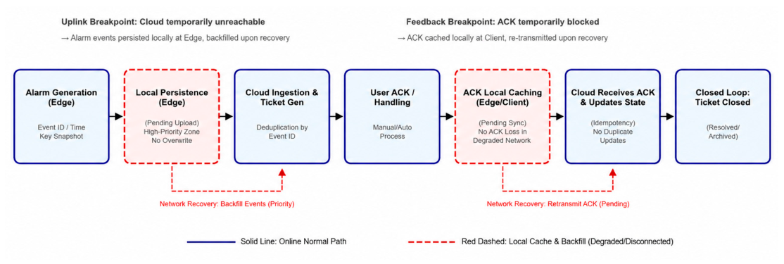
The alarm-event closed-loop lifecycle and the corresponding buffering points are illustrated in Figure 5.
Within this framework, the edge layer plays a key supporting role in the alarm closed loop. Specifically, when an alarm is generated, the edge layer creates a locally persistent record that preserves information such as the event identifier, occurrence time, source device, key state snapshots, and current handling status. When the edge–cloud link becomes unstable, the edge layer must also support temporary storage of alarm events, recovery backfill, and state alignment. In this way, even if alarms cannot be uploaded to the cloud in real time during disconnection, the corresponding records can be retained locally and prioritized during recovery.
From the perspective of closed-loop integrity, two major failure points exist in the alarm path under degraded network conditions. The first is a delivery failure point, where an alarm event cannot be uploaded to the cloud in a timely manner because of network degradation, packet loss, or link interruption, preventing users from receiving risk information promptly. The second is a feedback failure point, where the user has already completed acknowledgment or handling, but the associated acknowledgment message and handling record cannot be returned reliably, resulting in a state mismatch in which the alarm has been acknowledged locally but not synchronized to the cloud. The former affects whether alarms are received promptly, whereas the latter affects whether a complete alarm closed loop can be established.
To address these failure points, both the alarm event itself and its state updates are incorporated into unified closed-loop management. The alarm event is encapsulated and stored locally immediately after it is generated at the edge layer. User acknowledgments, handling results, and related alarm-acknowledgment messages are then associated with the original alarm event and stored as separate state-update records. When the edge–cloud link is available, both the alarm event and its state updates are synchronized to the cloud in real time. When the link is constrained, the edge gateway writes the relevant content to a local pending-synchronization queue, and state alignment is completed during recovery through differential retransmission. Consequently, the alarm closed loop no longer depends on the success of a single real-time transmission, but instead becomes a process of local retention, recovery completion, and eventual alignment.
In summary, the degraded-network alarm closed-loop framework proposed in this paper can be described as follows. After an alarm is generated, it is first encapsulated as an event and stored persistently at the edge layer. When the link is available, it is uploaded to the cloud and delivered to users. User acknowledgment and handling results are subsequently recorded and synchronized as event-state updates. If any intermediate stage is interrupted by degraded network conditions or disconnection, the edge layer gives priority to completing the missing information during recovery, ultimately forming a traceable closed loop of delivery, acknowledgment, handling, and feedback. This framework aligns with the previously described control takeover and recovery-backfill mechanisms and provides the basis for the subsequent design and experimental evaluation of the alarm interaction mechanism.

4.2. Key Interaction Mechanisms

Under degraded network conditions and intermittent disconnections, stable alarm interaction depends not only on whether events can be retained and backfilled but also on whether users can clearly identify event states, distinguish historical information from real-time information, and avoid being overwhelmed by redundant alarms. This subsection therefore describes interaction designs intended to improve ordering stability, duplicate suppression, and offline handling capability in degraded-network scenarios.
With respect to ordering and presentation, the alarm list is no longer sorted solely by arrival time, but instead incorporates factors such as event risk level, handling status, and occurrence time. High-risk events that have not yet been acknowledged or handled are given display priority. Events that have already been acknowledged or handled locally but have not yet been synchronized to the cloud are marked with status labels such as “pending synchronization”. In addition, the system explicitly distinguishes event occurrence time from arrival time at the presentation layer, thereby reducing interference from historical alarms with real-time decision-making during recovery.
For duplicate suppression, the proposed mechanism addresses duplicate uploads, repeated triggering, and concentrated backfill that may occur during recovery. Alarms triggered repeatedly by the same device under the same rule within a short time window are merged for display, while persistent alarms are subject to throttling [30]. Historical alarms backfilled during recovery are presented using unified labels and collapsed views. These measures are designed to reduce concentrated alarm records during backfill rather than to claim that user cognitive load has been quantitatively evaluated in this study.
For handling feedback, the proposed mechanism supports offline alarm handling under degraded network conditions. When users acknowledge alarms or perform handling operations while the link is constrained, the corresponding acknowledgment messages and handling records are first written to a local pending-synchronization queue on the edge gateway. After link recovery, these records are re-associated with the corresponding alarm events and backfilled. The cloud performs idempotent processing of repeatedly received state updates based on event identifiers, while the edge layer continues retransmission only for unacknowledged differential content. Through these mechanisms, the system supports alarm-state consistency by retaining unsynchronized updates locally and retransmitting only unacknowledged differential records after recovery.

4.3. Materials and Methods: Simulation Setup and Evaluation Metrics

To evaluate the proposed mechanism under controlled and repeatable conditions, a scripted dynamic network-disturbance environment was constructed. The experiments examine four aspects: recovery-backfill behavior, control continuity during disconnection, alarm closed-loop reliability, and parameter sensitivity. To clarify the comparison setting used in the reported numerical results, Table 4 defines the two schemes compared in both the scripted simulations and the supplementary trace-driven recovery evaluation. The cloud-centric baseline represents cloud-dependent operation under degraded communication, whereas the proposed scheme integrates lease-based authority handover, edge takeover, fallback local control, event-prioritized differential backfill, and alarm-state persistence. No physical sensors, actuators, commercial greenhouse hardware, chemicals, reagents, commercial cell lines, or physical samples were used in the experiments; all evaluations were conducted in a scripted simulation environment. The simulation scripts and data analyses were implemented using Python 3.11 (Python Software Foundation, Wilmington, DE, USA).
This definition is used to make the baseline assumption explicit before presenting the simulation settings and recovery results. For the additional recovery-backfill ablation analysis reported in Section 5.6, an intermediate baseline was also included. This baseline, denoted as edge buffering without event prioritization, retains edge-side buffering and rate-limited recovery backfill, but removes event-prioritized transmission. In this setting, all buffered records are placed in a single shared recovery queue and transmitted without distinguishing high-priority event records from general operational data.
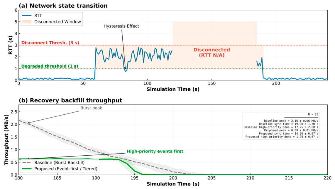
The total simulation duration was 240 s with a time step of 1 s. The scenario comprised four stages: online (0–60 s), degraded (60–120 s), disconnected (120–180 s), and recovery (180–240 s). The operational state machine uses RTT, PLR, and consecutive no-response duration; however, in the control-state-transition simulations, the scripted disturbance is driven primarily by RTT, while PLR is varied separately in the alarm experiments.
To make the network-impairment model explicit, RTT and PLR were used for different purposes in the simulation experiments. The scripted RTT profile was used to drive the network-state transition, control-authority switching, and recovery-phase timing. It determines when the system enters the online, degraded, disconnected, and recovery stages, and it is also used to illustrate the hysteresis behavior in Figure 6a. By contrast, PLR was not varied simultaneously with the scripted RTT profile in the control-continuity experiment. Instead, PLR was independently swept from 0% to 30% in the alarm closed-loop experiment to evaluate ACK success rate and final delivery completeness under different packet-loss conditions. This separation was adopted so that the effect of RTT-driven state switching on control continuity and the effect of packet loss on alarm delivery completeness could each be evaluated independently, without mutual confounding.
A short-term RTT drop was inserted during the degraded stage to illustrate how hysteresis suppresses unnecessary switch-back behavior. The main parameters are summarized in Table 5.
To further reduce the dependence on fully scripted recovery disturbances, a supplementary trace-driven recovery evaluation was conducted using a public 5G testbed measurement dataset [31]. The dataset contains measured RTT, throughput, jitter, location information, and a packet-loss-related measurement field. In this study, the 20231115-raspberry/oai_ue_metrics.db measurement file was used because it provided more measurement records than the alternative on-board-unit file. Invalid RTT records were excluded, and the remaining RTT and throughput samples were used to introduce real network-measurement fluctuations into the recovery-backfill simulation.
The RTT samples were converted from milliseconds to seconds before being interpreted together with the network-state determination logic described in Table 1. The throughput samples were normalized and used to scale the available recovery-backfill budget, so that the backfill process was affected by measured network-capacity fluctuations rather than by a fully handcrafted recovery profile. The loss-related field was used only as a relative impairment indicator, rather than being directly interpreted as the absolute PLR threshold in Table 1, because its magnitude reflects the measurement setting of the public 5G testbed. The same cloud-centric baseline and proposed backfill mechanisms were then evaluated under this trace-driven recovery sequence. This supplementary setting is intended to provide trace-driven simulation evidence and should not be interpreted as field deployment or hardware-in-the-loop validation.

5. Results and Discussion

5.1. Recovery-Phase Backfill Performance

During recovery, the baseline scheme adopted burst backfill, whereas the proposed scheme employed an event-prioritized, hierarchically rate-limited differential backfill strategy. As shown in Figure 6b, the baseline scheme exhibited a peak throughput of approximately 2.16 ± 0.06 MB/s, a total synchronization completion time of approximately 19.9 ± 1.7 s, and a high-priority event completion time of approximately 17.3 ± 2.7 s. In contrast, the proposed scheme reduced peak throughput to approximately 0.69 ± 0.01 MB/s, shortened the total synchronization completion time to approximately 14.5 ± 1.0 s, and further reduced the high-priority event completion time to approximately 2.0 ± 0.7 s. These results indicate that, under the scripted recovery scenario, event prioritization and hierarchical rate limiting reduced the initial backfill peak and allowed high-priority events to be completed earlier. Under the present script settings, this improvement mainly came from transmitting high-priority records before general operational data, rather than from uniformly delaying all uploads.

5.2. Control Continuity During Disconnection

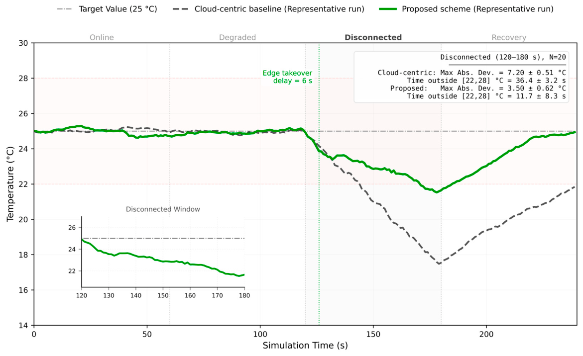
For the control-continuity experiment during disconnection, the target temperature was set to 25 °C and the safe range was defined as 22–28 °C. The same external cooling disturbance was applied to both schemes. In addition, the proposed scheme incorporated practical constraints, including a 6 s edge-takeover delay, first-order actuator lag, and an upper bound on control step size. Figure 7 presents representative temperature trajectories together with statistical results from 20 repeated trials.
Based on the 20 repeated trials, the cloud-centric baseline yielded a mean maximum absolute deviation of approximately 7.20 ± 0.51 °C within the disconnection window, with a mean time outside the safe range of approximately 36.4 ± 3.2 s. The corresponding values for the proposed scheme were approximately 3.50 ± 0.62 °C and 11.7 ± 8.3 s, respectively. These results show that, after accounting for factors such as takeover delay and actuator lag, edge takeover cannot completely eliminate the performance degradation caused by disconnection, but it can substantially reduce temperature drift and markedly shorten the duration outside the safe range. Thus, the proposed scheme mitigated control degradation in the simulated disconnection window, but it did not preserve nominal control performance.

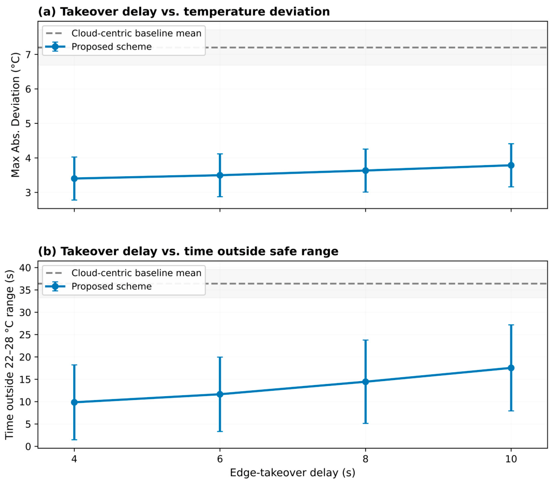
5.3. Sensitivity to Edge-Takeover Delay

To further assess the appropriateness of the parameter settings, the edge-takeover delay was selected for sensitivity analysis. A total of 20 repeated trials were conducted for each of four settings, namely 4 s, 6 s, 8 s, and 10 s. The results are shown in Figure 8.
Based on the simulation statistics, the cloud-centric baseline yielded a mean maximum absolute deviation of approximately 7.20 ± 0.51 °C and a mean time outside the safe range of approximately 36.4 ± 3.2 s. For the proposed scheme, when the edge-takeover delay was set to 4 s, 6 s, 8 s, and 10 s, the corresponding mean maximum absolute deviations were approximately 3.40 ± 0.62 °C, 3.50 ± 0.62 °C, 3.63 ± 0.62 °C, and 3.79 ± 0.63 °C, respectively. The corresponding mean times outside the safe range were approximately 9.85 ± 8.38 s, 11.65 ± 8.32 s, 14.45 ± 9.33 s, and 17.55 ± 9.63 s. Overall, shorter takeover delays allowed the edge layer to suppress temperature drift more promptly during disconnection and to reduce the time outside the safe range. However, within the 4–6 s range, the performance gain had already begun to level off. The relatively large standard deviation of the time-outside-safe-range metric indicates sensitivity to random disturbances and to the initial state at the onset of disconnection, but the mean trend remains consistent: longer takeover delays lead to weaker control performance.

5.4. Alarm Closed-Loop Reliability

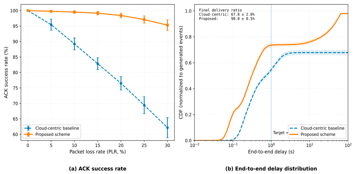
In the alarm closed-loop experiment, the proposed mechanism was evaluated using two metrics: ACK success rate and end-to-end delay distribution. Figure 9a compares the ACK success rates under varying packet loss rates (PLRs). As PLR increased, the ACK success rate of the baseline scheme declined more rapidly. In contrast, by incorporating local persistence and recovery-backfill mechanisms, the proposed scheme maintained a higher overall closed-loop acknowledgment success rate. According to the simulation statistics, at PLR = 20%, the ACK success rate was approximately 76.5 ± 2.2% for the baseline scheme and approximately 98.4 ± 0.8% for the proposed scheme. Overall, as PLR increased, the baseline ACK success rate decreased more clearly, whereas the proposed scheme maintained a higher ACK success rate in the tested PLR range. This result is consistent with the use of local persistence and recovery backfill for retransmitting unsynchronized acknowledgment records.
Figure 9b further presents the aggregated end-to-end delay distribution from the 20 repeated trials. The cumulative distribution function (CDF) was normalized by the total number of generated events. Because the baseline scheme permanently lost events during the disconnected phase, its curve did not ultimately reach 1.0. In contrast, the proposed scheme utilized the recovery phase to backfill events that could not be delivered promptly during disconnection. According to the simulation statistics, the final delivery ratio was approximately 67.8 ± 2.0% for the baseline scheme and approximately 98.0 ± 0.5% for the proposed scheme. As indicated by the curves, the proposed scheme maintained a relatively high real-time delivery ratio near the 1 s target and further improved final delivery completeness during recovery. Together with Figure 9a, these results show that the proposed scheme mainly improved final delivery completeness and ACK closed-loop success rate in the simulated alarm scenario, while maintaining a comparable proportion of events delivered near the 1 s target.

5.5. Supplementary Trace-Driven Recovery Evaluation

To examine whether the recovery-backfill behavior remained consistent under measured network fluctuations, public 5G testbed measurement data were introduced into the original recovery-backfill simulation as a supplementary trace-driven setting. The purpose of this supplementary evaluation was not to establish deployment-level performance bounds, but to examine whether the relative behavior observed under the scripted disturbance profile remained visible when real network-capacity fluctuations were included in the disturbance modeling.
As shown in Table 6, the trace-driven recovery profile led to higher backfill peaks and longer synchronization times than the scripted recovery profile, especially for the cloud-centric baseline. This indicates that measured network-capacity fluctuations can increase recovery cost and make burst backfill less stable. Under the trace-driven setting, the cloud-centric baseline showed a peak backfill throughput of 2.32 ± 0.25 MB/s, a total synchronization time of 22.75 ± 3.21 s, and a high-priority event completion time of 20.45 ± 3.22 s. In contrast, the proposed scheme maintained a lower peak backfill throughput of 0.76 ± 0.09 MB/s and completed high-priority events within 2.35 ± 0.57 s, while the total synchronization time remained 14.90 ± 1.04 s.
Compared with the scripted setting, the proposed scheme showed a slightly higher recovery peak and a slightly longer high-priority event completion time under the trace-driven profile. This result is expected because the measured throughput trace introduces additional variation into the available recovery budget. Nevertheless, the qualitative behavior remained consistent: event prioritization and hierarchical rate limiting reduced the initial backfill peak and allowed high-priority event records to be synchronized earlier than the cloud-centric baseline.

5.6. Ablation Analysis of Recovery Backfill

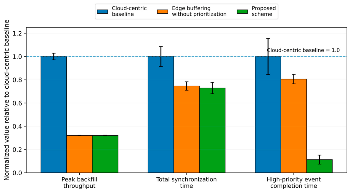
To further address the baseline-strengthening concern and to clarify the contribution of event prioritization in the recovery-backfill mechanism, an additional ablation baseline was added. This baseline, denoted as edge buffering without event prioritization, preserves edge-side buffering and rate-limited recovery backfill, but removes event-prioritized transmission. In this setting, all buffered records are placed in a single shared recovery queue and transmitted without distinguishing high-priority event records from general operational data.
Values are normalized to the cloud-centric baseline; lower values indicate better recovery performance. Numerical values are reported in Table 7.
As shown in Figure 10 and Table 7, the edge-buffering ablation baseline reduced the peak backfill throughput compared with the cloud-centric baseline because recovery traffic was rate-limited at the edge side. However, without event prioritization, high-priority event records still had to wait behind general operational data in the shared recovery queue, and their completion time remained 13.90 ± 0.70 s. In contrast, the proposed scheme completed high-priority event synchronization within 1.95 ± 0.67 s. This result indicates that edge buffering and rate limiting mainly reduce burst backfill traffic, whereas event-prioritized transmission is responsible for the earlier completion of high-priority records.

5.7. Security and Safety Considerations

The proposed mechanism involves security-sensitive operations, including cloud-to-edge control delivery, control-lease handover, edge-side fallback control, alarm acknowledgment, local persistence, and recovery backfill. In practical deployments, these operations should be protected by authentication, integrity checking, replay protection, and access control mechanisms. In particular, cloud commands, control leases, alarm acknowledgments, and event-state updates should be associated with authenticated identities and should be verified before execution or synchronization.
For command and event-log integrity, control commands, ACK messages, and backfilled event records should carry sequence identifiers, timestamps, and integrity-protection fields so that modified, duplicated, or replayed messages can be detected. During recovery, the sequence-number and batch-acknowledgment mechanisms described in this paper can support deduplication and differential retransmission, but deployment-level implementations should further ensure that timestamps and identifiers cannot be forged or reused by unauthorized entities.
Local persistence during disconnection also introduces storage-security requirements. Event logs, pending acknowledgment records, and fallback-control records stored at the edge gateway should be protected against unauthorized access and tampering. For example, local storage should enforce permission control and should preserve sufficient audit information for post-recovery inspection. If an edge gateway is compromised, the attacker may forge control states, modify local event logs, or interfere with authority handback. Therefore, gateway compromise detection, secure boot, trusted configuration storage, and protected update mechanisms are important for practical deployment.
From a safety perspective, the fallback local-control rules in this study are intended to bound local actions during simulated disconnection and to maintain basic control continuity. They should not be interpreted as a formally verified functional-safety policy. In field deployments, acceptable operating ranges, actuator limits, safe states, and abnormality conditions should be defined according to crop requirements, equipment characteristics, and site-specific operational constraints. Additional validation is required before these rules can be used as safety-assurance measures in production greenhouse systems.
Therefore, the present study focuses on the communication-degradation mechanism, recovery backfill, and alarm-state synchronization under simulation and trace-driven settings. A complete deployment-ready system should further integrate cybersecurity protection, access-control policies, gateway-compromise assumptions, and formal safety analysis. These issues will be addressed in future work together with field validation and hardware-in-the-loop testing.

5.8. Discussion

Overall, Figure 6, Figure 7, Figure 8, Figure 9 and Figure 10 show relative improvements in recovery backfill, temperature control during disconnection, and alarm-loop completion under the scripted simulation settings. The supplementary trace-driven results in Table 6 further suggest that the recovery-backfill behavior remains qualitatively consistent when measured network-capacity fluctuations are introduced. The ablation comparison in Section 5.6 further shows that edge buffering and rate limiting reduce burst recovery traffic, while event prioritization contributes to the substantially earlier synchronization of high-priority event records. The recovery results are mainly reflected in a lower backfill peak and earlier completion of high-priority events, which are consistent with the prioritization and rate-limiting design. The control-continuity experiment also shows that edge takeover mitigates, rather than eliminates, temperature drift under disconnection. Meanwhile, the alarm experiments show higher final delivery completeness and ACK success rate when local persistence and recovery backfill are enabled. These findings should be interpreted as evidence of relative mechanism effectiveness under the present scripted and trace-driven simulation settings, not as absolute performance bounds for real greenhouse deployments. The security and safety considerations discussed in Section 5.7 also indicate that deployment-level authentication, integrity protection, access control, and safety analysis are necessary before practical application. Although the supplementary trace-driven evaluation reduces reliance on fully scripted disturbances, broader validation with field-deployed greenhouse IoT platforms or hardware-in-the-loop testbeds is still required.

6. Conclusions

This paper proposed an end–edge–cloud collaborative mechanism for supporting control continuity and alarm-loop completion in solar greenhouse IoT systems under degraded network conditions and intermittent disconnections. The mechanism coordinates network-state determination, control-authority allocation, edge takeover, recovery-phase differential backfill, and event-based alarm management to reduce control interruption and support alarm-state synchronization when edge–cloud communication is impaired.
Under the current scripted degraded-network simulation settings, the results showed relative improvements compared with the cloud-centric baseline. During recovery, event prioritization and hierarchical rate limiting reduced the backfill peak and allowed high-priority events to be synchronized earlier. The supplementary trace-driven recovery evaluation showed a similar qualitative trend when public 5G testbed measurement fluctuations were introduced. The added ablation analysis further indicates that edge buffering and rate limiting mainly reduce burst recovery traffic, whereas event-prioritized transmission contributes to earlier synchronization of high-priority records. During disconnection, edge takeover reduced temperature deviation and shortened the time outside the safe range. At the alarm-interaction layer, the simulations showed higher ACK success rates and final delivery completeness when local persistence and recovery backfill were enabled. Sensitivity analysis of takeover delay further indicated that shorter edge-takeover delays helped suppress control drift in the early stage of disconnection, although parameter settings still require a trade-off between control performance and implementation complexity.
The present conclusions are derived mainly from scripted degraded-network disturbances, a supplementary trace-driven recovery evaluation, and an event-level simulation environment; they have not yet been validated on a real greenhouse platform or in a hardware-in-the-loop system. Furthermore, more complex environmental models, device-response constraints, and issues related to security authentication and access control were not examined in depth. Future work will focus on validation with field-collected greenhouse network traces, hardware-in-the-loop platforms, and field deployments, as well as adaptive parameter optimization and security-mechanism design.

Supplementary Materials

The following supporting information can be downloaded at: https://www.mdpi.com/article/10.3390/app16115191/s1. minimal dataset and scripts supporting the reported simulation results, including README.txt; Source_Data.xls, source data for Figure 6, Figure 7, Figure 8, Figure 9 and Figure 10 and Table 6 and Table 7; trace_driven_recovery_backfill_windows.py, script for trace-driven recovery-backfill analysis; trace_driven_recovery_results.csv, summary results of the trace-driven recovery evaluation; trace_driven_recovery_trace_summary.csv, summary of the public 5G testbed trace samples; ablation_recovery_backfill_analysis.py, script for the recovery-backfill ablation analysis; and ablation_recovery_backfill_results.csv, results of the ablation comparison.

Author Contributions

Conceptualization, H.B. and Y.Z.; methodology, H.B.; software, H.B.; validation, J.J. and T.G.; formal analysis, H.B.; investigation, H.B.; resources, J.J. and T.G.; data curation, H.B.; writing—original draft preparation, H.B.; writing—review and editing, Y.Z., J.J. and T.G.; visualization, H.B.; supervision, Y.Z.; project administration, Y.Z.; funding acquisition, Y.Z. All authors have read and agreed to the published version of the manuscript.

Funding

This research was funded by the Research Start-up Fund for the Directed Training Program, Heilongjiang Bayi Agricultural University, grant number XDB202301. The APC was funded by Heilongjiang Bayi Agricultural University.

Institutional Review Board Statement

Not applicable.

Informed Consent Statement

Not applicable.

Data Availability Statement

The minimal dataset supporting the reported simulation results is provided in the Supplementary Materials, which includes README.txt, Source_Data.xls, trace_driven_recovery_backfill_windows.py, trace_driven_recovery_results.csv, trace_driven_recovery_trace_summary.csv, ablation_recovery_backfill_analysis.py, and ablation_recovery_backfill_results.csv. The public 5G testbed measurement dataset used for the supplementary trace-driven recovery evaluation is available from Zenodo, as cited in reference [31].

Acknowledgments

During the preparation of this manuscript, the authors used ChatGPT (GPT-5.5 Thinking, OpenAI, San Francisco, CA, USA) for language polishing. The authors reviewed and edited the output and take full responsibility for the content of this publication.

Conflicts of Interest

The authors declare no conflicts of interest. The funders had no role in the design of the study; in the collection, analyses, or interpretation of data; in the writing of the manuscript; or in the decision to publish the results.

References

  1. Hosny, K.M.; El-Hady, W.M.; Samy, F.M. Technologies, Protocols, and Applications of Internet of Things in Greenhouse Farming: A Survey of Recent Advances. Inf. Process. Agric. 2025, 12, 91–111. [Google Scholar] [CrossRef]
  2. Zhang, M.; Yan, T.; Wang, W.; Jia, X.; Wang, J.; Klemeš, J.J. Energy-Saving Design and Control Strategy towards Modern Sustainable Greenhouse: A Review. Renew. Sustain. Energy Rev. 2022, 164, 112602. [Google Scholar] [CrossRef]
  3. Yu, P.; Teng, F.; Zhu, W.; Shen, C.; Chen, Z.; Song, J. Cloud–Edge–Device Collaborative Computing in Smart Agriculture: Architectures, Applications, and Future Perspectives. Front. Plant Sci. 2025, 16, 1668545. [Google Scholar] [CrossRef]
  4. Zhang, Y.; Yu, H.; Zhou, W.; Man, M. Application and Research of IoT Architecture for End-Net-Cloud Edge Computing. Electronics 2023, 12, 1. [Google Scholar] [CrossRef]
  5. Andriulo, F.C.; Fiore, M.; Mongiello, M.; Traversa, E.; Zizzo, V. Edge Computing and Cloud Computing for Internet of Things: A Review. Informatics 2024, 11, 71. [Google Scholar] [CrossRef]
  6. Fernando, N.; Shrestha, S.; Loke, S.W.; Lee, K. On Edge-Fog-Cloud Collaboration and Reaping Its Benefits: A Heterogeneous Multi-Tier Edge Computing Architecture. Future Internet 2025, 17, 22. [Google Scholar] [CrossRef]
  7. Ribeiro Junior, F.M.; Kamienski, C.A. Data Resilience System for Fog Computing. Comput. Netw. 2021, 195, 108218. [Google Scholar] [CrossRef]
  8. Jesus, B.; Lins, F.; Laranjeiro, N. An Approach to Assess Robustness of MQTT-Based IoT Systems. Internet Things 2025, 31, 101590. [Google Scholar] [CrossRef]
  9. Chen, W.-H.; You, F. Semiclosed Greenhouse Climate Control under Uncertainty via Machine Learning and Data-Driven Robust Model Predictive Control. IEEE Trans. Control Syst. Technol. 2022, 30, 1186–1197. [Google Scholar] [CrossRef]
  10. Chen, W.-H.; You, F. Smart Greenhouse Control under Harsh Climate Conditions Based on Data-Driven Robust Model Predictive Control with Principal Component Analysis and Kernel Density Estimation. J. Process Control 2021, 107, 103–113. [Google Scholar] [CrossRef]
  11. Iqbal, M.Z.; Islam, M.N.; Kabir, M.S.N.; Gulandaz, M.A.; Reza, M.N.; Jang, S.-H.; Chung, S.-O. Comparison of Heating Modules for Suspension-Type Multipoint Temperature Variability Management in Smart Greenhouses. Smart Agric. Technol. 2023, 5, 100296. [Google Scholar] [CrossRef]
  12. Zhang, L.; Liu, X.; Li, T.; Ji, J.; Zhao, L. A Microenvironment Prediction Model for Chinese Solar Greenhouses Based on the Bond Graph Approach. PLoS ONE 2022, 17, e0267481. [Google Scholar] [CrossRef]
  13. Ariesen-Verschuur, N.; Verdouw, C.; Tekinerdogan, B. Digital Twins in Greenhouse Horticulture: A Review. Comput. Electron. Agric. 2022, 199, 107183. [Google Scholar] [CrossRef]
  14. Kalyani, S.; Collier, R. A Systematic Survey on the Role of Cloud, Fog, and Edge Computing Combination in Smart Agriculture. Sensors 2021, 21, 5922. [Google Scholar] [CrossRef] [PubMed]
  15. Qureshi, R.; Mehboob, S.H.; Aamir, M. Sustainable Green Fog Computing for Smart Agriculture. Wirel. Pers. Commun. 2021, 121, 1379–1390. [Google Scholar] [CrossRef]
  16. Shi, H.; Li, Q. Edge Computing and the Internet of Things on Agricultural Green Productivity. J. Supercomput. 2022, 78, 14448–14470. [Google Scholar] [CrossRef]
  17. El Jarroudi, M.; Kouadio, L.; Delfosse, P.; Bock, C.H.; Mahlein, A.-K.; Fettweis, X.; Mercatoris, B.; Adams, F.; Lenné, J.M.; Hamdioui, S. Leveraging Edge Artificial Intelligence for Sustainable Agriculture. Nat. Sustain. 2024, 7, 846–854. [Google Scholar] [CrossRef]
  18. Chen, W.-H.; You, F. Decarbonization through Smart Energy Management: Climate Control in Building-Integrated Rooftop Greenhouses for Urban Agriculture across Various Climate Conditions. J. Clean. Prod. 2024, 458, 142544. [Google Scholar] [CrossRef]
  19. Chen, W.-H.; You, F. Sustainable Energy Management and Control for Decarbonization of Complex Multi-Zone Buildings with Renewable Solar and Geothermal Energies Using Machine Learning, Robust Optimization, and Predictive Control. Appl. Energy 2024, 372, 123802. [Google Scholar] [CrossRef]
  20. Zhou, J.; Shang, J.; Chen, T. Performance Analysis for Stochastic Anomaly Detectors with On/Off-Delay Timers. Automatica 2025, 173, 112073. [Google Scholar] [CrossRef]
  21. Ortiz, G.; Zouai, M.; Kazar, O.; García-de-Prado, A.; Boubeta-Puig, J. Atmosphere: Context and Situational-Aware Collaborative IoT Architecture for Edge–Fog–Cloud Computing. Comput. Stand. Interfaces 2022, 79, 103550. [Google Scholar] [CrossRef]
  22. Tian, J.; Jia, H.; Bai, W. CCECGP: Causal Consistency Model of Edge–Cloud Collaborative Based on Grouping Protocol. J. Supercomput. 2023, 79, 8401–8424. [Google Scholar] [CrossRef]
  23. Dui, H.; Wang, J.; Zhu, T.; Xing, L. Maintenance Optimization Methodology of Edge Cloud Collaborative Systems Based on a Gateway Cost Index in IIoT. Reliab. Eng. Syst. Saf. 2024, 251, 110370. [Google Scholar] [CrossRef]
  24. Tian, J.; Jia, H.; Bai, W. CCESHP: Causal Consistency Model of Edge Storage Based on Hash Ring and Partial Geo-Replication. Comput. J. 2023, 66, 2874–2886. [Google Scholar] [CrossRef]
  25. Zyrianoff, I.; Gigli, L.; Montori, F.; Sciullo, L.; Kamienski, C.; Di Felice, M. CACHE-IT: A Distributed Architecture for Proactive Edge Caching in Heterogeneous IoT Scenarios. Ad Hoc Netw. 2024, 156, 103413. [Google Scholar] [CrossRef]
  26. Tian, J.; Bai, W.; Jia, H. PGCE: A Distributed Storage Causal Consistency Model Based on Partial Geo-Replication and Cloud-Edge Collaboration Architecture. Comput. Netw. 2022, 212, 109065. [Google Scholar]
  27. Colarusso, C.; Falco, I.; Zimeo, E. Business Continuity of Cloud-Based IoT Applications through a Seamless Continuum. Internet Things 2025, 33, 101723. [Google Scholar] [CrossRef]
  28. Rao, H.R.M.; Zhou, B.; Brown, K.; Chen, T.; Shah, S.L. Alarm Correlation Analysis with Applications to Industrial Alarm Management. Control Eng. Pract. 2024, 143, 105812. [Google Scholar] [CrossRef]
  29. Rahaman, M.H.; Alinezhad, H.S.; Chen, T. Real-Time Classification and Early Warning of Industrial Alarm Floods Using Modified TF-IDF Methods. Control Eng. Pract. 2025, 164, 106485. [Google Scholar] [CrossRef]
  30. Yang, S.; Zhang, T.; Zhai, Y.; Wang, K.; Zhao, G.; Tu, Y.; Cheng, L. Frequent Alarm Pattern Mining of Industrial Alarm Flood Sequences by an Improved PrefixSpan Algorithm. Processes 2023, 11, 1169. [Google Scholar] [CrossRef]
  31. Gavrielides, A. DEDICAT6G-5G Testbed Measurements-CGB, Zenodo 2024, Version 1.0; CERN: Geneva, Switzerland, 2024. [CrossRef]
Figure 1. End–edge–cloud–user architecture and three interaction links.
Applsci 16 05191 g001
Figure 2. Network-state finite state machine (FSM) transitions and hysteresis determination. Solid arrows indicate immediate downgrading under worse network conditions, whereas dashed arrows indicate hysteresis-constrained upward transitions during recovery.
Applsci 16 05191 g002
Figure 3. Edge takeover and local buffering mechanism under degraded network conditions.
Applsci 16 05191 g003
Figure 4. Hierarchical backfill and consistency verification during the recovery phase.
Applsci 16 05191 g004
Figure 5. Alarm-event closed-loop lifecycle and buffering at failure points with recovery backfill. Solid arrows indicate the normal online interaction path, whereas dashed red arrows indicate local caching and recovery backfill/retransmission under degraded or disconnected conditions.
Applsci 16 05191 g005
Figure 6. Network-state transitions and recovery-backfill characteristics under degraded network conditions. (a) Network-state transition and hysteresis behavior. (b) Recovery-backfill throughput comparison between the cloud-centric baseline and the proposed scheme.
Applsci 16 05191 g006
Figure 7. Control-continuity simulation results during the disconnected phase.
Applsci 16 05191 g007
Figure 8. Sensitivity analysis of edge-takeover delay. (a) Effect of edge-takeover delay on the maximum absolute temperature deviation. (b) Effect of edge-takeover delay on the time outside the predefined safe temperature range. The grey shaded area indicates the predefined safe temperature range of 22–28 °C.
Applsci 16 05191 g008
Figure 9. Comparison of acknowledgment (ACK) success rate and end-to-end delay distribution under degraded network conditions. (a) ACK success rate under different packet loss rates. (b) End-to-end delay distribution of alarm-event delivery.
Applsci 16 05191 g009
Figure 10. Ablation comparison of recovery-backfill strategies.
Applsci 16 05191 g010
Table 1. Quantitative thresholds for network-state determination under degraded network conditions.
StateRound-Trip Time (RTT) (s)Packet Loss Rate (PLR) (%)Consecutive No-Response Duration (s)Interpretation
Online≤1≤5≤3Normal interaction performance
Degraded1–35–203–10Elevated latency and/or moderate packet loss, leading to unstable interactions
Disconnected>3 or N/A>20 or N/A>10Link unavailable; local edge takeover is activated
Table 2. Control-lease lifecycle and edge-takeover triggering rules.
StageTrigger or ConditionControl-Authority ActionPurpose or Explanation
Lease creationThe cloud sends configuration parameters or control commands with a validity period under online conditions.The edge gateway accepts fresh and non-duplicated commands and stores the latest valid configuration.Defines cloud-side primary control with edge-side execution.
Lease renewal or updateA newer, valid configuration or command is received before the current lease expires.The edge gateway updates the stored configuration after freshness and duplicate checks.Keeps the local configuration consistent with the latest cloud-side strategy when communication is available.
Degraded communication with a valid leaseThe link is degraded, but the current lease remains valid.The cloud remains the primary controller, while the edge gateway executes the latest valid configuration and buffers local records.Avoids unnecessary control handover under temporary network degradation.
Lease expiry or disconnected stateThe control lease expires, or the network state becomes disconnected, according to the state-determination rule.Control authority shifts to the edge gateway, and the edge gateway executes fallback local control based on the latest valid configuration.Prevents control interruption when the cloud becomes unreachable.
Recovery after reconnectionThe link changes from disconnected to degraded or online.Control authority is not returned to the cloud immediately. The edge gateway first reports high-priority event records and control-action summaries.Reduces the risk of state inconsistency during recovery.
Consistency verificationHigh-priority event backfill is completed, and cloud–edge state consistency is checked.The cloud and edge compare synchronized records and unresolved differential content.Confirms whether the system state is sufficiently aligned before handback.
Handback to cloud-side primary controlCloud–edge states are largely consistent, and a fresh, valid configuration or lease is available.The system returns to the normal mode of cloud-side primary control with edge-side execution.Restores normal collaboration after recovery without abrupt authority switching.
Table 3. Fallback local-control rules used during disconnection.
Trigger or ConditionLocal-Control RuleConstraint or BoundaryPurpose
Edge–cloud link enters the disconnected state and the cloud control lease expiresThe edge gateway switches to fallback local control using the latest valid configuration.No new global optimization strategy is generated at the edge side.Maintain basic control execution when cloud commands are unavailable.
Sensor data are temporarily delayed or unavailableThe edge gateway uses the most recent valid sensor reading within the configured validity window; if the reading is invalid, the corresponding control update is skipped or limited.Sensor values outside the validity window are not used for aggressive control adjustment.Avoid abrupt actuator changes caused by missing or stale sensor data.
Environmental variable exceeds the acceptable rangeThe edge gateway applies bounded corrective actions according to the latest valid control parameters.The adjustment step is limited by the configured maximum step size.Reduce temperature drift while avoiding excessive actuator changes.
Actuator feedback is delayed or abnormalThe edge gateway limits further control changes for the affected actuator and records the abnormal state locally.The mechanism does not infer actuator health beyond the configured abnormality condition.Avoid repeated or conflicting actuator commands during disconnection.
High-priority event or alarm is generated during disconnectionThe event record is stored locally with occurrence time, source, and current state information.The record is prioritized for recovery backfill after reconnection.Preserve event traceability for later cloud–edge state alignment.
Link recovers from the disconnected stateThe edge gateway keeps fallback control active during recovery until high-priority records are backfilled and state consistency is checked.Cloud-side primary control is restored only after recovery verification and a fresh, valid configuration is available.Avoid abrupt handback and reduce cloud–edge state inconsistency.
Table 4. Definition of the two schemes used in the reported numerical comparisons.
SchemeIncluded MechanismsExcluded MechanismsPurpose
Cloud-centric baselineCloud-side control and direct cloud–edge communicationEdge takeover, control lease, fallback local control, event-prioritized differential backfill, and local alarm-state persistenceMain baseline used to represent cloud-dependent operation under degraded communication
Proposed schemeControl lease, edge takeover, fallback local control, event-prioritized differential backfill, and alarm-state persistenceNone of the listed core mechanisms is excludedIntegrated mechanism evaluated against the cloud-centric baseline in the scripted simulations and the supplementary trace-driven recovery evaluation
Table 5. Main simulation settings for the collaborative control and alarm closed-loop experiments.
Parameter CategoryParameterValue/SettingDescription
Network-disturbance scriptTotal simulation duration240 sTotal simulation time
Network-disturbance scriptTime step1 sDiscrete simulation interval
Network-disturbance scriptStage divisionOnline: 0–60 s; degraded: 60–120 s; disconnected: 120–180 s; recovery: 180–240 sScripted degraded-network disturbance profile
Network-state determinationRTT thresholdsDegraded: 1 s; disconnected: 3 sConsistent with Table 1
Control parametersTarget temperature25 °CGreenhouse temperature-control target
Control parametersSafe range22–28 °CTarget temperature ± 3 °C
Control parametersCloud/edge control gains0.08/0.10Cloud-side primary control and edge takeover
Control parametersActuator lag coefficient/maximum adjustment step0.20/0.08Dynamic-response constraints
Control parametersEdge-takeover delay6 sDefault setting for Figure 7
Sensitivity analysisTakeover-delay levels4 s, 6 s, 8 s, and 10 sSettings for Figure 8
Recovery backfillBaseline backfill budgetmin (2.8, 0.30 + 0.22 × backlog)Burst backfill strategy
Recovery backfillProposed-scheme backfill budgetHigh-priority events: 0.20 MB; total budget cap: 0.70 MBEvent prioritization and hierarchical rate limiting
Recovery backfillEdge-buffering ablation budgetTotal budget cap: 0.70 MB; single shared queueRate-limited recovery backfill without event prioritization
Alarm simulationPLR range0–30%, increment 5%Settings for Figure 9a
Alarm simulationACK experiment scale20 repeated trials, 200 alarms per trialFigure 9a
Alarm simulationDelay-CDF experiment scale20 repeated trials, 1000 events per trialFigure 9b
Alarm simulationLocal persistence failure probability/maximum retransmission attempts0.02/3Alarm recovery-backfill mechanism
Alarm simulationAdditional backfill delay0.6–8.0 sRetransmission of disconnection-period events after recovery
Note: This table lists the key parameters required to interpret network-state determination, control switching, recovery backfill, and alarm closed-loop simulations. Other implementation details are omitted for brevity.
Table 6. Supplementary comparison between scripted and trace-driven recovery settings.
Recovery SettingSchemePeak Backfill Throughput (MB/s)Total Synchronization Time (s)High-Priority Event Completion Time (s)
Scripted recovery profileCloud-centric baseline2.16 ± 0.0619.90 ± 1.7017.25 ± 2.68
Scripted recovery profileProposed scheme0.69 ± 0.0114.50 ± 0.971.95 ± 0.67
Trace-driven recovery profileCloud-centric baseline2.32 ± 0.2522.75 ± 3.2120.45 ± 3.22
Trace-driven recovery profileProposed scheme0.76 ± 0.0914.90 ± 1.042.35 ± 0.57
Note: The trace-driven recovery profile was generated from public 5G testbed measurement records. The loss-related field was used as a relative impairment indicator rather than as an absolute PLR value.
Table 7. Ablation comparison of recovery backfill with and without event prioritization.
SchemePeak Backfill Throughput (MB/s)Total Synchronization Time (s)High-Priority Event Completion Time (s)
Cloud-centric baseline2.16 ± 0.0619.90 ± 1.7017.25 ± 2.68
Edge buffering without event prioritization0.694 ± 0.00514.85 ± 0.7313.90 ± 0.70
Proposed scheme0.69 ± 0.0114.50 ± 0.971.95 ± 0.67
Note: Values are reported as mean ± standard deviation over 20 repeated trials. The edge-buffering ablation baseline retains rate-limited edge backfill but removes event-prioritized transmission.
Disclaimer/Publisher’s Note: The statements, opinions and data contained in all publications are solely those of the individual author(s) and contributor(s) and not of MDPI and/or the editor(s). MDPI and/or the editor(s) disclaim responsibility for any injury to people or property resulting from any ideas, methods, instructions or products referred to in the content.