

Development of an Immersive VR-Based Training Platform Integrating FMECA for Wind Turbine Maintenance: FMECA-VR-0.1 Prototype


 ,
,  ,
,  ,
,  and
and
Abstract
1. Introduction
- Development of a novel immersive platform that integrates engineering-based reliability methods (FMECA, QRCM, MMM) within an immersive VR training environment.
- Application to a real wind turbine system, demonstrating the feasibility of embedding analytical maintenance processes into interactive 3D scenarios.
- Preliminary qualitative assessment indicating potential improvements in user engagement and conceptual understanding, without formal quantitative validation.
- Identification of future research pathways, including digital-twin integration, real-time sensor data, multi-subsystem expansion, and quantitative assessment of learning performance.
2. Literature Review and Background
2.1. Industry 4.0 and Its Impact on Maintenance Engineering
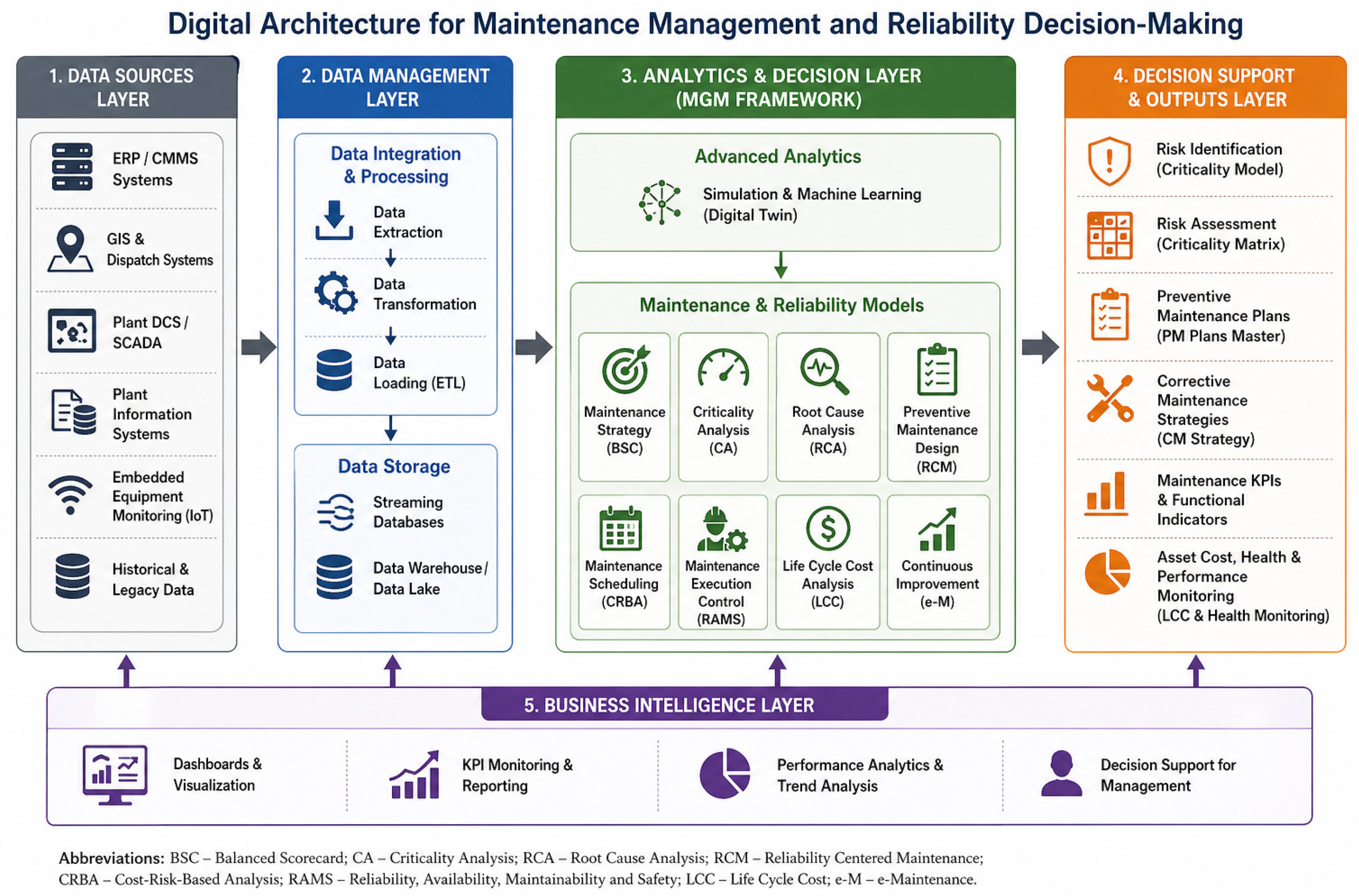
2.2. Cyber-Physical Systems, IoT, and the Emergence of the Industrial Metaverse
2.3. VR and Immersive Tools for Maintenance Training
- -
- -
- -
2.4. FMECA and Risk-Based Maintenance Frameworks
2.5. Identified Research Gaps and Motivation for the Present Study
- -
- VR systems rarely integrate engineering methodologies such as FMECA.
- -
- No existing tools combine FMECA, QRCM, MMM, and VR into a unified immersive VR-based platform.
- -
- There is limited research on immersive training for wind turbine maintenance using formal risk methodologies.
- -
- Few studies apply VR in combination with asset management frameworks (ISO 55000, MMM) [20].
3. Methodological Framework
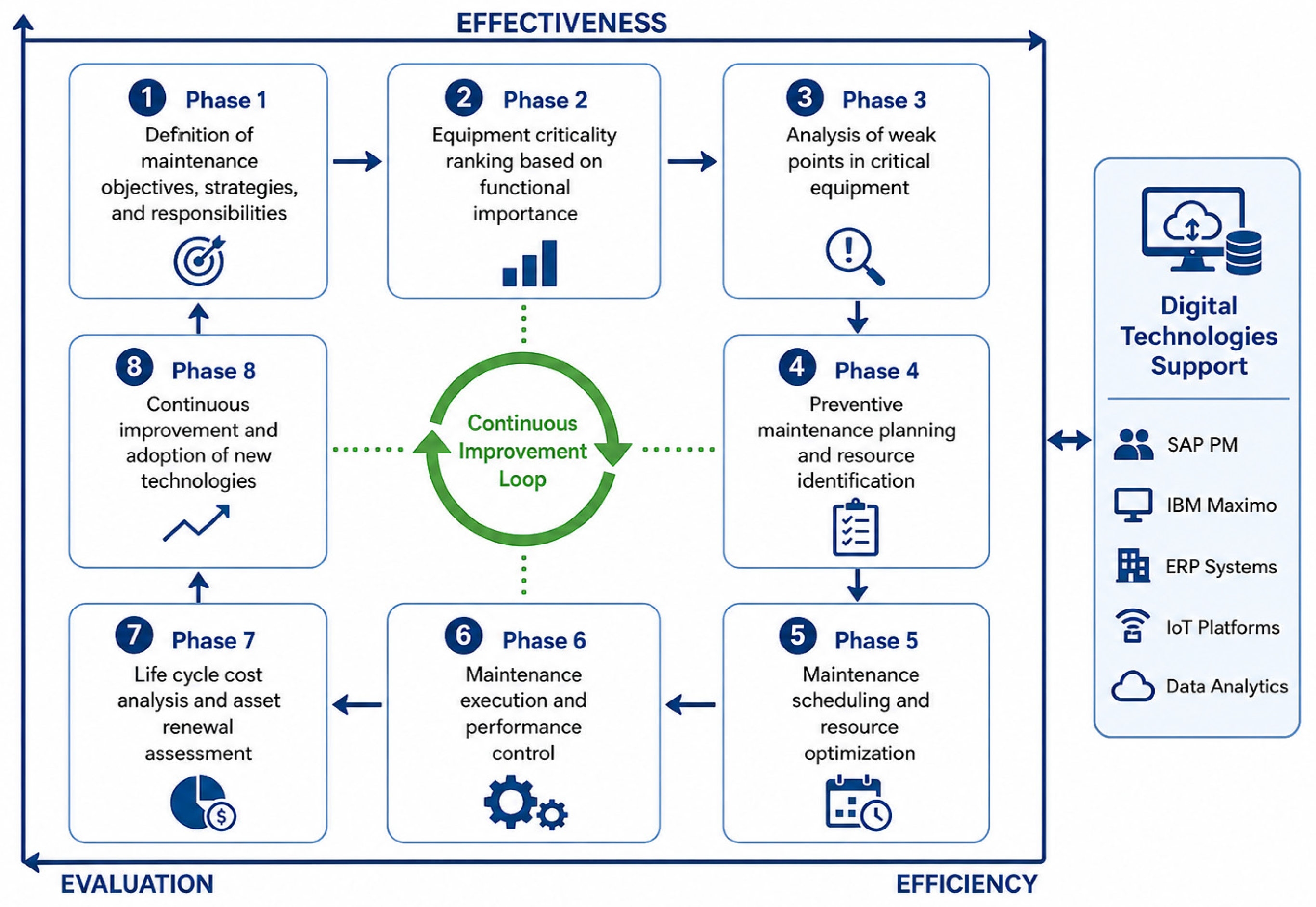
3.1. Overview of the Maintenance Management Model (MMM)
- -
- Phase 1. Techniques for defining a maintenance management strategy. To ensure that maintenance operational objectives and strategies are not misaligned with overall business goals [13], techniques such as the Balanced Scorecard (BSC) can be introduced and implemented in the maintenance area. The BSC is customized for each organization and enables the creation of key performance indicators (KPIs) to measure maintenance performance, aligned with strategic objectives [13]. Unlike conventional control-oriented measures, the BSC centers its analysis on corporate strategy and vision, emphasizing the achievement of performance goals. These goals are defined through a participatory process involving both internal and external stakeholders, including company leadership, operational staff, and end users. As a result, maintenance performance measures are directly linked to the overall success of the organization.
- -
- Phase 2. Techniques for ranking production assets. Once maintenance objectives and strategies are defined, various qualitative and quantitative techniques are available to systematically classify assets based on their criticality for achieving business objectives. Many quantitative approaches employ variations in probabilistic risk assessment (PRA) or generate probabilistic risk indices (PRI) for each asset. Assets with higher indices are prioritized. In cases where historical data is unavailable, qualitative techniques may be applied to ensure effective initial decision-making. After asset prioritization, a clear maintenance strategy must be defined for each category, to be refined over time.
- -
- Phase 3. Tools for eliminating weak points in high-impact equipment or systems. In critical assets, it is advisable to identify and eliminate chronic, recurring failures before developing maintenance plans. Conducting such can yield an early return on investment. One of the most widely used techniques for this purpose is Root Cause Analysis (RCA) [17], which identifies the physical, human, and latent causes of failures. Physical causes refer to the technical explanation for the failure, human causes involve errors or omissions that lead to failure, and latent causes relate to organizational or management deficiencies that enable those errors to persist. Addressing latent causes is typically the main focus of this phase.
- -
- Phase 4. Support for defining an effective preventive maintenance plan. Designing a preventive maintenance plan for a system requires identifying its functions and potential failure modes, and establishing tasks that ensure safety and cost-effectiveness. A structured methodology such as Reliability Centered Maintenance (RCM) [9] is commonly used to achieve this objective.
- -
- Phase 5. Optimization techniques for improving maintenance programs. Maintenance plans and programs can be optimized to improve the effectiveness and efficiency of the initial design. Optimization models differ based on the time horizon. Long-term models address capacity, spare inventory, and task intervals. Medium-term ones focus on scheduled shutdowns, while short-term models aim to enhance resource allocation and control. Both analytical and empirical approaches are employed, often requiring simplifications to manage complexity [18].
- -
- Phase 6. Monitoring and control of maintenance operations. Once maintenance activities are designed, planned, and scheduled, their execution must be monitored, and deviations controlled to meet business objectives and KPI targets. Many high-level KPIs are built from technical and economic sub-indicators, making it essential to capture accurate and aggregated maintenance data.
- -
- Phase 7. Lifecycle cost analysis and control. This phase evaluates the total cost of an asset throughout its lifecycle, including planning, R&D, production, operation, maintenance, and disposal. Lifecycle cost analysis depends heavily on reliability data such as failure rates, repair times, and spare part costs. It supports decisions about new equipment acquisition or replacement and offers three major benefits [20]:
- ○
- All costs associated with an asset become visible.
- ○
- It enables cross-functional analysis, e.g., how low R&D investment may increase future maintenance costs.
- ○
- It allows management to make accurate forecasts.
- -
- Phase 8. Techniques for continuous improvement in maintenance. Continuous improvement (CI) in maintenance is possible through emerging technologies in high-impact areas identified in earlier phases. Concepts such as Maintenance 4.0, e-maintenance, and e-manufacturing are key elements of Industry 4.0, which leverages ICT to create collaborative, multi-user corporate environments [4,10]. Maintenance 4.0 involves the integration of resources, services, and management tools to enable proactive, data-driven decisions. This support includes ICT, web-based, wireless, and infotronic technologies, and “e-maintenance” functions such as e-monitoring, e-diagnosis, and e-prognosis. Additionally, the active participation of maintenance personnel is critical to success. While high levels of knowledge, training, and expertise are required, the inclusion of simple, operator-driven tasks is essential to achieving high-quality maintenance and overall equipment effectiveness.
3.2. FMECA Structure and Criticality Assessment
- -
- Failure Mode: how a component or subsystem fails;
- -
- Cause: the underlying mechanism behind the failure;
- -
- Effect: the functional consequence at local, subsystem, and system levels;
- -
- Detection Method: existing means for identifying the onset of the failure;
- -
- Severity Level: qualitative estimation of impact on safety, production, quality, or cost;
- -
- Frequency or Occurrence: expected rate or probability of the failure;
- -
- Criticality: combined assessment of severity and frequency using the QRCM.
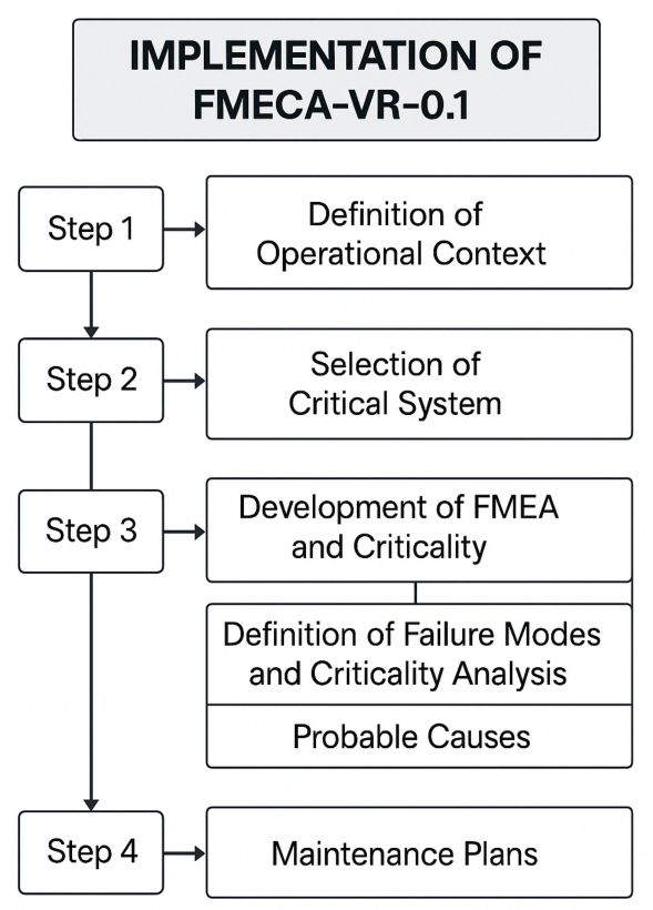
3.3. Integration of MMM and FMECA into the VR-Based Training Tool (FMECA-VR-0.1)
- -
- Stages 1 and 2 correspond to the development of the operational context and the criticality matrix (linked to Phase 2 of the MMM).
- -
- Stage 3 corresponds to the definition of failure modes, effects, and criticality (linked to Phase 4 of the MMM).
- -
- Stage 4 corresponds to the development of maintenance strategies (linked to Phases 4 and 5 of the MMM).
3.3.1. Stage 1. Operational Context
- -
- Operational Summary: Purpose of the system, equipment involved, processes, safety devices, and environmental objectives.
- -
- Personnel: Definition of shifts, operations, and quality parameters.
- -
- Process Breakdown: Structuring of the process into systems, definition of boundaries, and listing of components.
- -
- Operational profile.
- -
- Operating environment.
- -
- Quality/availability of required inputs (fuel, air, etc.).
- -
- Alarms and monitoring.
- -
- Spare parts policies, resources, and logistics.
- -
- P&IDs (Piping and Instrumentation Diagrams) of the system.
- -
- System schematics and/or block diagrams, typically developed from the P&IDs.
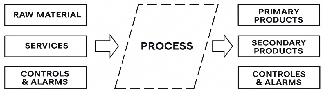
- Inputs can be categorized into three types:
- -
- Raw materials: Resources directly processed or transformed by the system or equipment (e.g., gas, crude oil, wood).
- -
- Services: Resources used by the process to transform raw materials (e.g., electricity, water, steam).
- -
- Controls: Inputs related to control systems and their effects on the equipment or processes. These are usually not recorded as separate functions, as their failure is generally associated with a loss of output signal at some point in the process.
- Outputs are associated with the inherent functions of the system and may be classified as:
- -
- Primary products: Represent the main purpose of the system, generally defined by production rate and quality standards.
- -
- Secondary products: Derived from primary functions performed by the system. Loss of secondary products can often lead to the failure of primary functions and may have catastrophic consequences.
- -
- Controls and alarms: Related to the system’s protection and control functions.
3.3.2. Stage 2. Equipment-Level Criticality Analysis
- -
- Define the scope and purpose of the analysis.
- -
- Establish importance criteria, such as safety, environment, production, cost, failure frequency, and repair time.
- -
- Select or develop a method to rank systems/equipment.
- -
- FF = Failure frequency per equipment (number of failures in a given time period)
- -
- C = Consequences of failures related to safety, environment, quality, production, etc.
- -
- SHE = Safety, Health, and Environmental Impact
- -
- IP = Impact of Production
- -
- CDF = Costs Direct of Failure
- -
- Failure Frequency (FF)1. Excellent: One occurrence after 8760 h.2. Good: At least one occurrence between 4380 and 8760 h.3. Average: At least one occurrence between 2190 and 4380 h.4. Poor: At least one occurrence between 730 and 2190 h.5. Very Poor: At least one occurrence within 730 h.
- -
- Failure Consequences (C)Safety, Health, and Environmental Impact (SHE)5. High impact: Fatalities or catastrophic environmental damage.4. Medium–high impact: Serious injuries and significant environmental damage.3. Low–medium impact: Minor injuries and no lasting environmental damage.2. Low impact: Slight environmental damage.1. No impact: No environmental effect.
- -
- Impact of Production (IP)5. 60–100% production loss [MW], (>40 h downtime).4. 40–60% production loss [MW], (20 < X < 40 h downtime).3. 35–40% production loss [MW], (5 < X < 20 h downtime).2. 25–35% production loss [MW], (1 < X < 5 h downtime).1. 0–25% production loss [MW], (<1 h downtime).
- -
- Costs Direct of Failure (CDF)5. Costs over USD 300,000.4. Costs between USD 100,000 and 299,999.3. Costs between USD 50,001 and 99,999.2. Costs between USD 5001 and 50,000.1. Costs below USD 5000.
- -
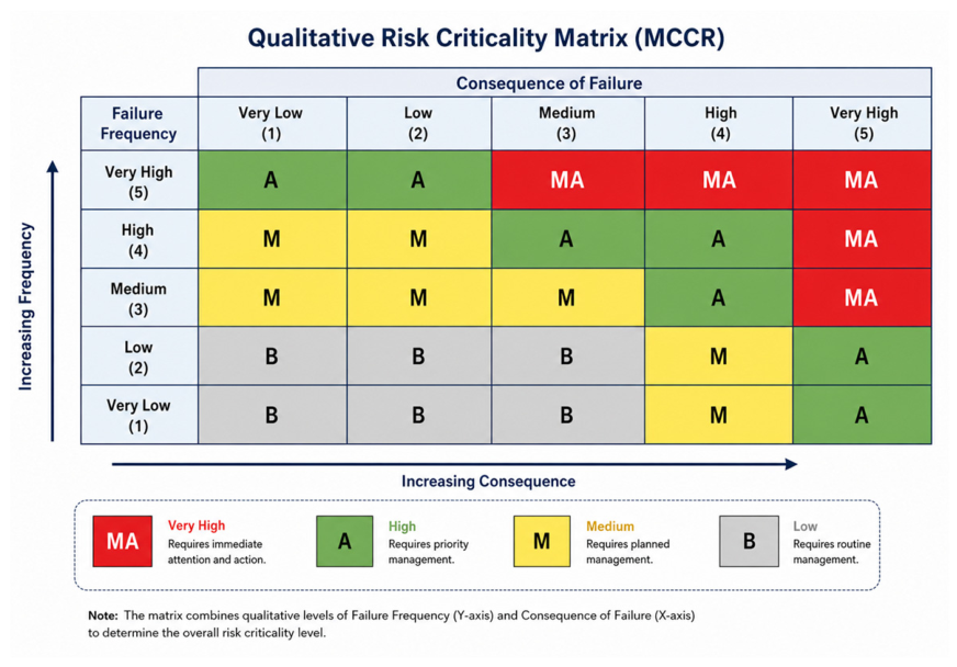
- Criticality Levels by Equipment (Based on QRCM—Figure 5):
| B | = | Low Criticality: Gray zone | 3 | ≤ | Cr | ≤ | 18 |
| M | = | Medium Criticality: Yellow zone | 9 | ≤ | Cr | ≤ | 27 |
| A | = | High Criticality: Green zone | 13 | ≤ | Cr | ≤ | 48 |
| MA | = | Very High Criticality: Red zone | 35 | ≤ | Cr | ≤ | 75 |
3.3.3. Stage 3. Failure Modes, Effects, and Criticality Analysis
Stage 3.1. Failure Modes
- -
- Generic lists of failure modes.
- -
- Operations and/or maintenance personnel with extensive experience with the asset.
- -
- Existing technical records and maintenance histories.
- -
- Asset manufacturers and suppliers.
- -
- Other users operating the same type of asset.
- -
- Burned-out electric motor (detail level: equipment)
- -
- Fractured impeller shaft (detail level: component)
- -
- Impeller jammed due to foreign objects (detail level: component)
- -
- Completely blocked suction line (detail level: component)
- -
- Worn mechanical seal (detail level: component)
- -
- Damaged piston ring in hydraulic cylinder (detail level: component)
Stage 3.2. Effects and Criticality of Failure Modes
- -
- What evidence confirms that the failure has occurred?
- -
- How does it affect safety and the environment?
- -
- How does it impact production or operations?
- -
- What are the operational consequences?
- -
- Is it necessary to shut down the process?
- -
- Is there an impact on quality? If so, how much?
- -
- Is there an impact on customer service?
- -
- Does it cause damage to other systems?
- -
- How much time is required to repair the failure (corrective actions)?
- -
- What is the economic loss caused by the failure (direct costs, production impact, environmental and safety costs, etc.)?
- -
- Failure Mode:Damaged piston rings in the hydraulic cylinder
- -
- Effects of Failure Mode:
- ○
- Visible/Not visible: Yes. No impact on safety or environment.
- ○
- Operational effects: The engine crankcase depressurizes, cylinder compression drops, oil wets the spark plug, smoke is observed in the exhaust, compression capacity is lost, and engine RPMs decrease.
- ○
- Corrective actions: Shut down the engine, depressurize the system, rotate the engine, position the connecting rods, secure the flywheel, loosen connecting rod bolts, remove the piston, inspect the rings, and replace them if necessary. Required personnel: 4 mechanics. Repair time: 16 h/failure.
- ○
- Production impact: USD 120,000/h. Total impact per failure: USD 1,920,000.
- -
- FF = Frequency of the failure mode (number of failures in a given time period)
- -
- C = Consequences of the failure mode in terms of safety, environment, quality, production, etc.
- -
- SHE = Impact on Safety and the Environment
- -
- IP = Impact on Production
- -
- CDF = Direct Failure Costs
- -
- Criticality Levels by Failure Mode (based on QRCM—Figure 5):
| B | = | Low Criticality: Gray zone | 3 | ≤ | Cr | ≤ | 18 |
| M | = | Medium Criticality: Yellow zone | 9 | ≤ | Cr | ≤ | 27 |
| A | = | High Criticality: Green zone | 13 | ≤ | Cr | ≤ | 48 |
| MA | = | Very High Criticality: Red zone | 35 | ≤ | Cr | ≤ | 75 |
Stage 3.3. Probable Causes
- -
- Failure Mode: Damaged piston rings in the hydraulic cylinder
- -
- Probable Cause: Accelerated wear due to increased temperature
3.3.4. Stage 4. Maintenance Plans
- -
- Preventive (proactive) maintenance
- -
- Corrective (reactive) maintenance, applied only when no effective preventive alternative exists.
Preventive (Proactive) Maintenance Activities
- -
- Condition-Based Maintenance (CBM)
- -
- Overhaul (Reconditioning)
- -
- Scheduled Replacement
- -
- Hidden Failure Detection
Corrective (Reactive) Maintenance Activities
- -
- Redesign
- -
- Run-to-Failure (Unscheduled Maintenance)
4. Application of the FMECA-VR-0.1 Tool in the Renewable Energy Sector
4.1. Stage 1: Definition of the Operational Context
- General system: Valle de los Vientos Wind Farm
- -
- Reference Data:Tower height: 80 mRotor diameter: 100 mEnvironmental conditions: Desert climate with high dust exposure and temperatures ranging from −5 °C to 40 °C
- -
- Controllers and Alarms:Generator overload alarmsVibration alarms in the gearboxAutomatic shutdown in extreme wind conditions (wind speeds > 25 m/s)Temperature monitoring in bearings and the generator
- Specific system description
- -
- Blades: Capture the wind’s kinetic energy and convert it into mechanical rotational energy.
- -
- Main Shaft Assembly: Transmits the rotational mechanical energy from the blades to the generator.
- -
- Gearbox (Multiplier): Increases the rotational speed of the main shaft.
- -
- Doubly-Fed Induction Generator (DFIG): Converts the rotational mechanical energy—transmitted through the shaft system—into electrical energy.
- -
- Frequency Converter: Manages and adapts the electrical energy generated by the DFIG to match grid standards in frequency and voltage.
- -
- Transformer: Adjusts or steps up the voltage of the generated electricity for safe and efficient transmission to the grid.
- -
- Electrical Panel: Also known as the electrical control cabinet, it manages, distributes, and protects the turbine’s electrical systems.
- -
- Yaw System: Orients the nacelle and blades toward the wind direction.
- Key process variables (power curve)
- -
- Minimum Operating Wind Speed:The turbine does not generate power until the wind speed reaches 3 m/s.
- -
- Power Growth:Between 3 m/s and 10 m/s, power increases linearly from 0 to 2000 kW.Between 10 m/s and 12 m/s, power stabilizes at 2000 kW.
- -
- Operational Stability:From 12 m/s onward, the turbine maintains a constant output of 2000 kW.
- -
- Safety Shutdown:If wind speeds exceed 25 m/s, the turbine shuts down to prevent damage.
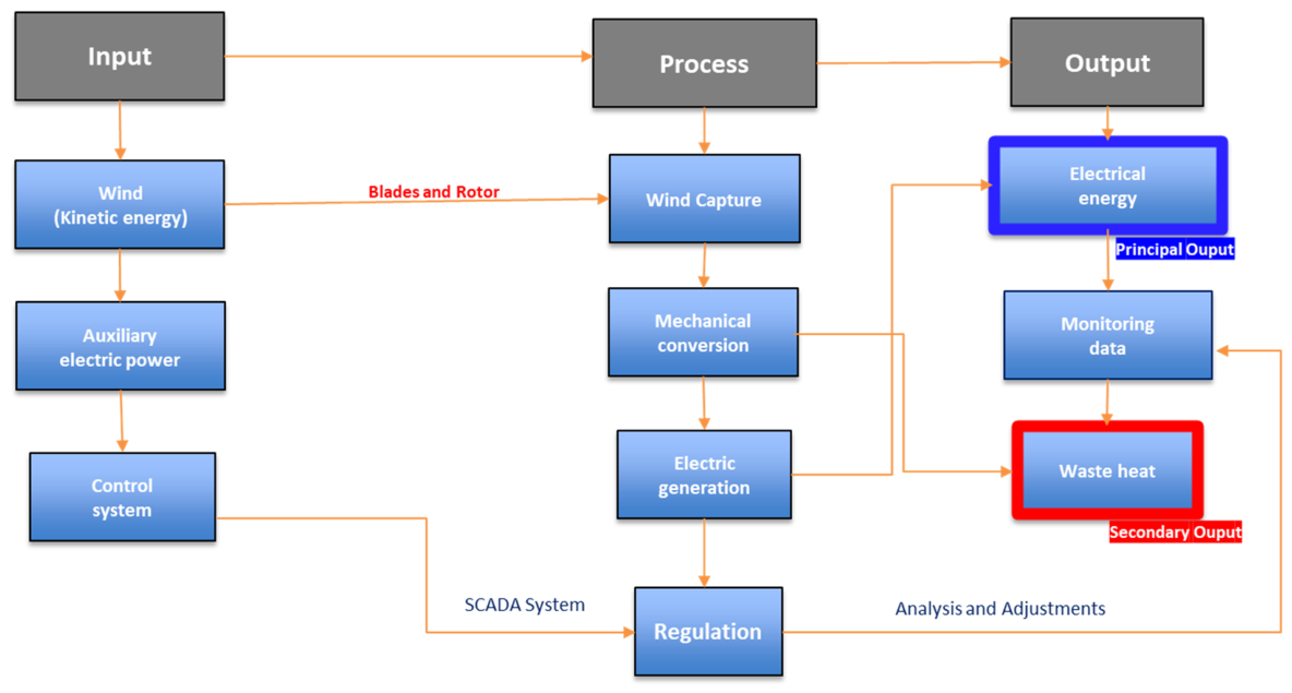
- Input—Process—Output (IPO) diagram
- -
- INPUT: The necessary resources for wind turbine operation include:
- Wind (Kinetic Energy): The primary input driving the rotor blades. Wind speed and direction determine how much energy can be captured.
- Auxiliary Electrical Power: Powers control systems, sensors, and blade/pitch adjustment when the turbine is not generating power.
- Control System: Receives monitoring and automated adjustment signals (via SCADA) to optimize performance and protect the equipment.
- -
- PROCESS: The wind turbine converts kinetic wind energy into electrical energy through the following steps:
- Wind capture: Rotor blades spin as they are impacted by wind.
- Mechanical conversion: The rotation is transmitted through the main shaft and accelerated via the gearbox.
- Power generation: The generator transforms mechanical energy into electrical energy through electromagnetic induction.
- Regulation: Control systems adjust blade pitch and yaw direction to maximize wind capture.
- Voltage transformation: An integrated transformer adjusts voltage for transmission to the substation.
- -
- OUTPUT: Products and by-products generated by the wind turbine include:
- Generated electrical power: The main output, ready to be delivered to the electrical grid via transmission lines.
- Monitoring and operational data: Real-time performance data transmitted to the SCADA system for analysis and control.
- Residual heat: A by-product of the energy conversion process, dissipated by the turbine’s ventilation systems.
4.2. Stage 2: Selection of the Critical System
- -
- Subsystems with Very High Criticality: 25% of total
- -
- Subsystems with High Criticality: 25% of total
- -
- Subsystems with Medium Criticality: 42% of total
- -
- Subsystems with Low Criticality: 8% of total
4.3. Stage 3: Development of FMECA and Criticality Analysis
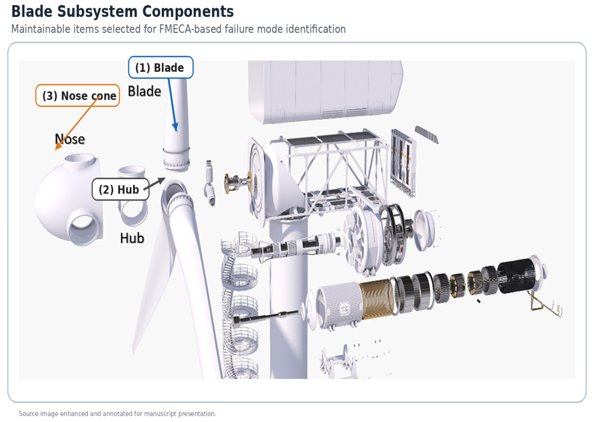
4.3.1. Definition of Failure Modes and Criticality Analysis
- -
- Blade Damage: Modern wind turbines typically use three blades to ensure lower oscillations and better balance of gyroscopic forces. These blades are mainly made of lightweight and highly durable materials such as carbon fiber and fiberglass combined with epoxy resin. They can reach lengths of up to 50 m and rotate at speeds ranging from 10 to 60 RPM. For large-scale turbines, the most common operating speeds are between 10 and 20 RPM. The blades are mounted on the turbine hub [37].
- -
- Hub Damage: The hub connects the blades and transmits the captured wind energy from the rotor to the gearbox. It is generally a hollow metal structure that acts as a rigid central piece [37].
- -
- Nose Cone Issues: The nose cone is a conical structure that faces the wind and directs it toward the drivetrain. Its aerodynamic shape helps prevent turbulence and protects the wind turbine from potential damage [37].
4.3.2. Definition of Probable Causes
4.4. Stage 4: Maintenance Plans
- -
- Select the blade subsystem for the development of action plans related to its physical failure modes.
- -
- Identify the three physical failure modes and their previously assigned criticality levels.
- -
- Define the probable causes for each failure mode.
- -
- Specify the maintenance tasks associated with each failure mode.
- -
- Estimate the execution frequency for each task.
- -
- Assign a responsible specialist for each task.
- -
- Estimate the annual cost of each maintenance plan.
- -
- Estimate the annual maintenance hours for each task.
5. Development of the Immersive VR-Based Training Platform Prototype: FMECA-VR-0.1
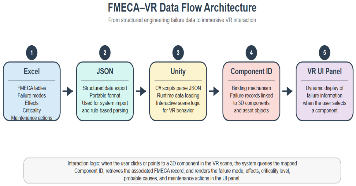
5.1. FMECA-VR-0.1 Data Integration and Interaction Model
- Data Structuring:
- 2.
- Data Import into Unity:
- 3.
- Component Binding:
- 4.
- Interactive Visualization:
- -
- Failure mode description
- -
- Criticality level
- -
- Probable causes
- -
- Recommended maintenance actions
5.2. Functional Requirements
- -
- The system will allow users to visualize the Valle de los Vientos Wind Farm, located in the Calama region.
- -
- The system will support the manipulation and visualization of a 3D model of the VESTAS V100–2.0 MW wind turbine.
- -
- The system will provide access to documents related to the FMEA table and criticality assessment for the blade subsystem.
- -
- The system will provide access to documents related to the action plan for physical failure modes of the turbine blades.
- -
- The system will enable visualization of elements related to the wind turbine’s subsystems.
5.3. Technical Requirements
- -
- Unity 3D 2021+ for environment design and VR scripting
- -
- C# for interaction and scenario logic
- -
- Blender version 4.3 2024 for 3D model preparation
- -
- XML/JSON for engineering data import
- -
- Meta SDK for Oculus Quest integration
- -
- Oculus Quest 2 VR headset
- -
- Oculus controllers
- -
- PC with NVIDIA GPU for development and testing
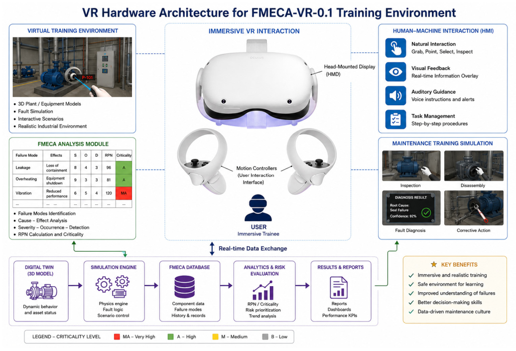
5.4. System Architecture
- -
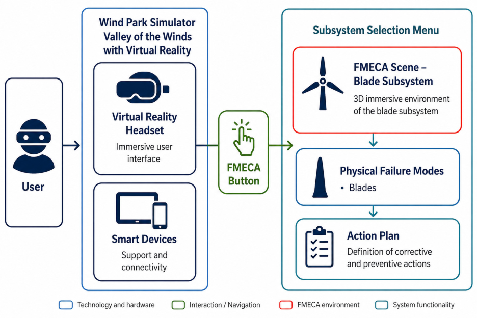
- Inputs: The Oculus Quest 2 system provides the following inputs to the immersive application:
- Virtual Reality Headset: Allows the user to visualize virtual reality environments, which is fundamental to achieving an immersive experience.
- Joysticks: Composed of two handheld controllers (one in each hand), these allow the user to interact with objects and elements in the virtual environment. These controls provide an intuitive way to manipulate and navigate the platform.
- -
- Outputs: The system outputs correspond to the visual elements generated and displayed through the Virtual Reality headset. During the immersive session, the user will be able to view components, diagrams, and relevant information panels within the virtual space.
- Start Menu Scene: The simulator includes a start menu screen, which displays the operational context of the V100–2.0 MW wind turbine. It also features a screen showing the most critical subsystems, where the blade subsystem is identified as the most critical. Additionally, a button is provided to access the FMECA scene of the wind turbine.
- FMECA Scene: In this section, users can visualize the FMECA tool applied to the blade subsystem, where the criticality levels, probable causes, and corrective action plans are presented in an interactive and educational format, overlaid on the 3D model of the blades.
5.5. Practical Implementation of the Digital Tool: FMECA-VR-0.1
5.5.1. Start Menu Scene
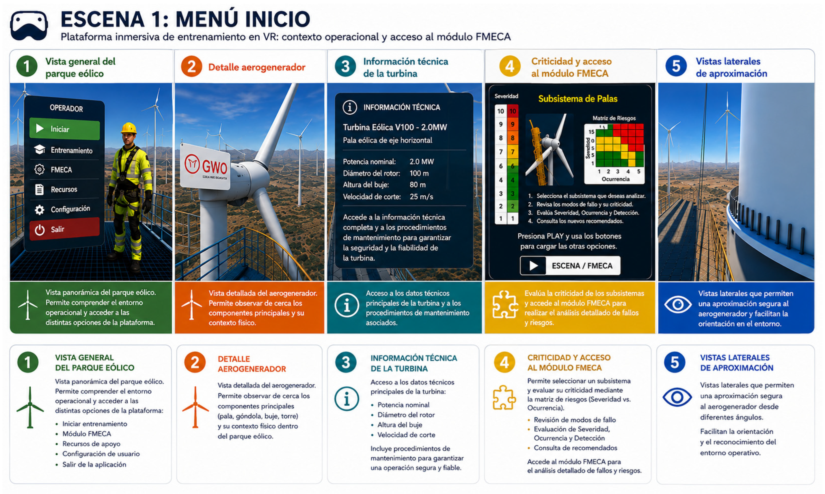
- -
- Panoramic view of the wind farm, where turbines are in operation, and their spatial layout within the environment can be observed.
- -
- Technical information about the VESTAS V100–2.0 MW wind turbine, including its operational context, main components, operator safety elements, and certifications.
- -
- Access to fault analysis modules, where critical subsystems such as the blades are presented, along with a link to the FMECA scene.
5.5.2. Description of the Main Tabs
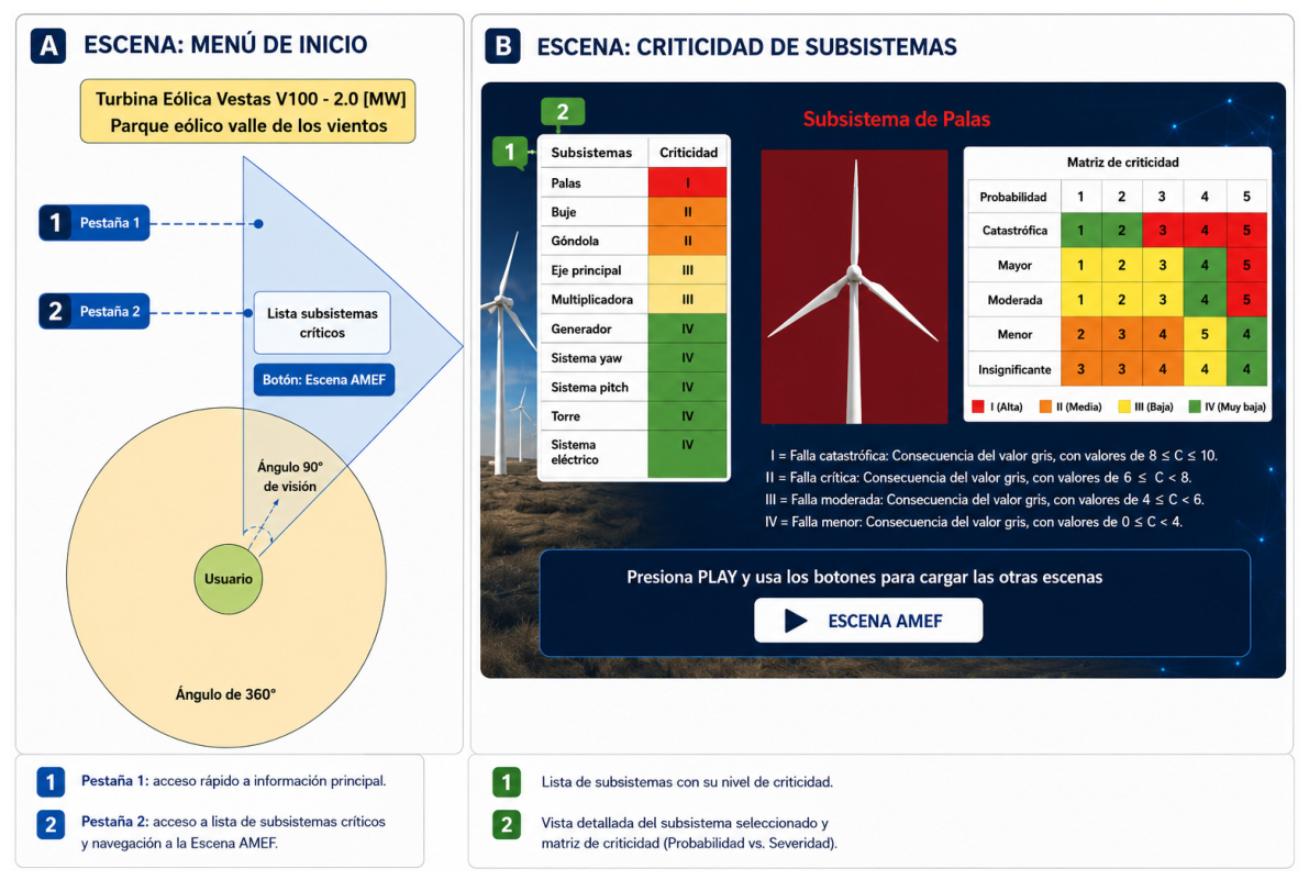
- -
- Operational Context: The image shows the visual representation of the Operational Context within the FMECA-VR-0.1 platform, used for maintenance training of wind turbines in a virtual environment
- -
- Criticality System: The image displays the subsystem criticality analysis structure within the FMECA-VR-0.1 tool. Through the immersive VR-based training platform, users can identify and rank key wind turbine components, focusing on those with the greatest impact on system reliability and maintainability (Figure 12).
5.5.3. FMECA Scene
- -
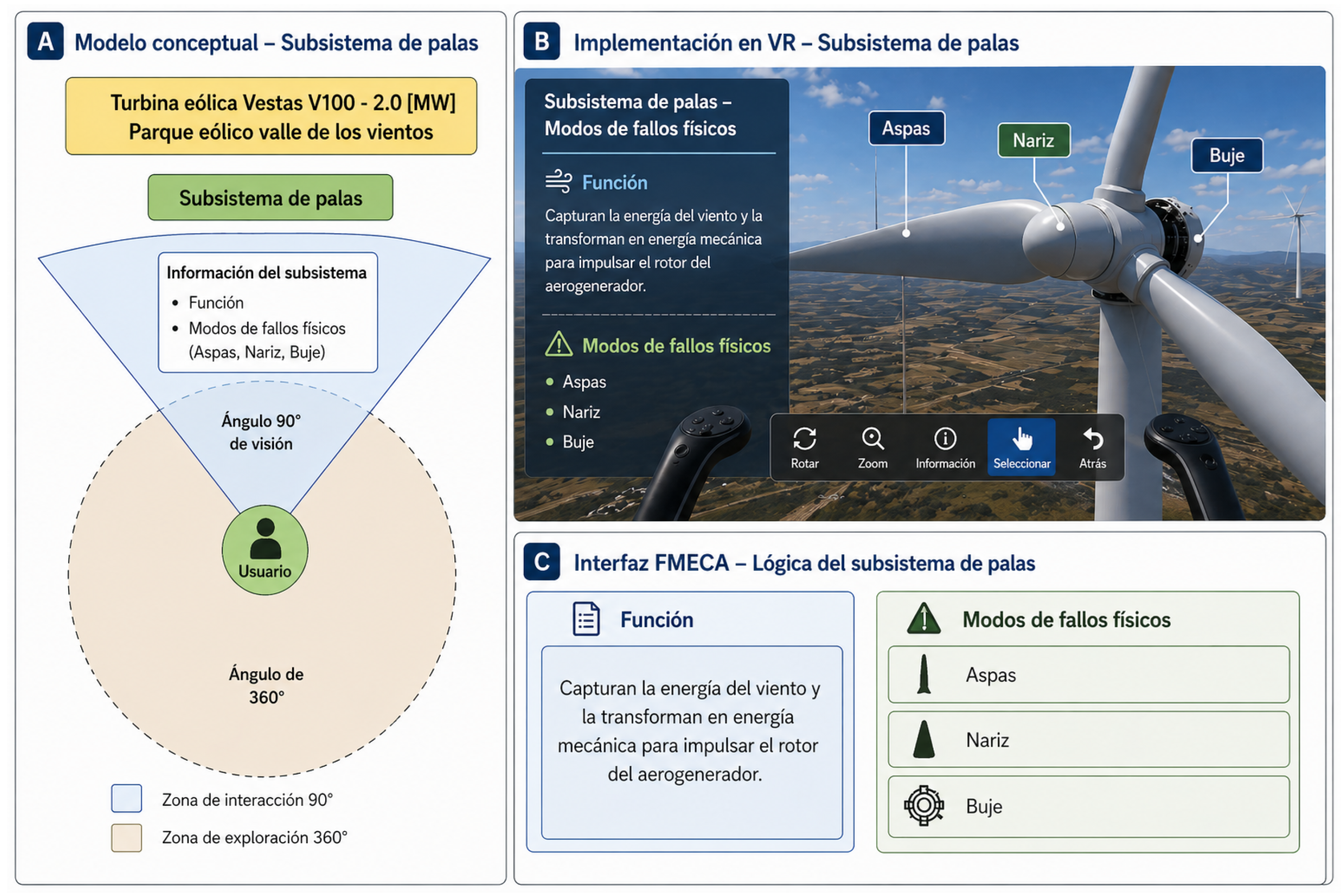
- Function and Physical Failure Modes (Figure 13):
- ○
- Circular diagram offering a 90° field of view for the user within a 360° Virtual Reality environment, with numbered tabs marking various sections of information.
- ○
- Analysis categories include:
- Function (e.g., capturing and converting wind energy)
- Physical failure modes (blades, nose cone, and hub).
- ○
- 3D visualization of a wind turbine in the Virtual Reality space with floating labels identifying components and related failures.
- -
- Effects, Failure Criticality, and Probable Causes: The user maintains a 90° view field in a 360° immersive environment, navigating through tabs 1 to 8.
- ○
- Active tabs:
- Tab 3—Effect: Loss of aerodynamic performance
- Tab 4—Criticality: Indicates criticality levels (Very High for blades, Medium for nose and hub)
- Tab 5—Probable Causes: Includes faults such as cracks, delamination, and bending in the blades
- -
- Action Plan and Assigned Specialist:
- ○
- Active tabs:
- Tab 6—Action Plan: Outlines maintenance actions including thermographic and ultrasound inspections (monthly), X-ray inspections (quarterly), and symptomatic maintenance
- Tab 7—Responsible Specialist: Assigns maintenance responsibility to the electromechanical technician
- -
- Demonstration Video: A visual demonstration of the tool in use is presented in the following video (duration: 3 min), available on the LinkedIn platform [44]:🔗 https://www.linkedin.com/feed/update/urn:li:activity:7200352283866349568/, accessed on 20 March 2026
- -
- Additional interface visualizations are provided in the Supplementary Material (Figures S1–S6) to avoid redundancy and improve readability of the main manuscript.
6. Economic Analysis of the Immersive VR Prototype: FMECA-VR-0.1
- -
- Total Estimated Cost of Pilot Version—FMECA-VR-0.1. By adding the totals from Table 6 and Table 7, the overall development cost of the pilot version of the FMECA-VR-0.1 prototype is:
- CLP $50,955,137 (Chilean Pesos, approximately USD $50,000)
- -
- Travel and accommodation costs for trainees
- -
- Equipment downtime during on-site training
- -
- Safety risks during real inspections
- -
- Remote training without travel costs
- -
- Zero operational downtime
- -
- Safe simulation of critical failure scenarios
7. Practical Implications, Industrial Benefits, and Limitations
- -
- Enhanced Learning Efficiency. An immersive VR-based training platform that has the potential to improve retention and comprehension by allowing technicians to experience failure mechanisms rather than reading about them.
- -
- Safer Training Environment. Users are not exposed to the real hazards of turbine maintenance, such as:
- -
- Working at height,
- -
- Rotating machinery,
- -
- High-voltage systems,
- -
- Harsh environmental conditions.
- -
- Reduction in Training Time. VR enables:
- -
- Faster familiarization with components,
- -
- Repetitive practice without downtime,
- -
- Reduced dependency on on-site turbine access.
- -
- Integration of Engineering Logic. Unlike conventional VR simulators, the FMECA-VR-0.1 platform embeds:
- -
- Failure modes,
- -
- Risk matrices,
- -
- Engineering consequences,
- -
- Maintenance strategies.
- -
- Scalability Across Industries. The architecture can be extended to:
- -
- Mechanical systems,
- -
- Power generation assets,
- -
- Mining equipment,
- -
- Manufacturing lines,
- -
- Chemical and process plants.
7.1. Limitations of the Current Prototype (FMECA-VR-0.1)
- -
- Limited Scope to a Single Subsystem. The platform currently focuses on the blade subsystem only. A full turbine training tool would require modeling:
- Gearbox,
- Generator,
- Yaw and pitch systems,
- Hydraulic and control systems.
- -
- No Real-Time Data Integration. The prototype does not yet incorporate:
- SCADA data
- Condition monitoring systems
- Digital twin streaming
- Vibration or thermal data
- -
- Simplified 3D Models. Models are optimized for VR performance, not full engineering detail.
- -
- No Quantitative User Performance Metrics. Assessment is qualitative. Advanced tracking (reaction time, error rates, task completion) is not yet implemented.
- -
- Limited Multi-User or Collaborative Features. The current version is single-user. Immersive VR-based training platform multi-user collaboration is planned for future releases.
- -
- First, the current version models only one subsystem of the wind turbine—the blade subsystem. While this choice reflects its high criticality, it restricts the ability to validate the methodology across a broader range of mechanical, electrical, and hydraulic components. Expanding the platform to include additional subsystems is required to fully assess its generalizability.
- -
- Second, the VR environment is based on static engineering data derived from the FMECA and criticality analysis. The system does not yet incorporate real-time operational inputs, such as SCADA variables, vibration signatures, temperature trends, or historical maintenance records. Consequently, the platform cannot simulate dynamic failure progression or predictive maintenance scenarios.
- -
- Third, the 3D models were optimized for performance on the Oculus Quest 2, which limits their geometric fidelity and prevents precise engineering simulations. The focus of the prototype is pedagogical rather than operational, meaning that visualization accuracy may not be sufficient for high-detail inspection or engineering design purposes.
- -
- Fourth, although preliminary validation with students and technicians indicates positive educational outcomes, the study does not include a controlled experimental evaluation with quantitative performance metrics. Further research is needed to measure learning gains, error reduction, and long-term retention compared to traditional training methods.
- -
- Finally, the economic analysis presents an estimate of development costs based on a prototype implementation and may not fully reflect the complexities of a commercial-scale deployment, such as licensing, support, scalability, and multi-user capabilities.
7.2. Improvements to Be Included in the FMECA-VR-0.1 Tool
- -
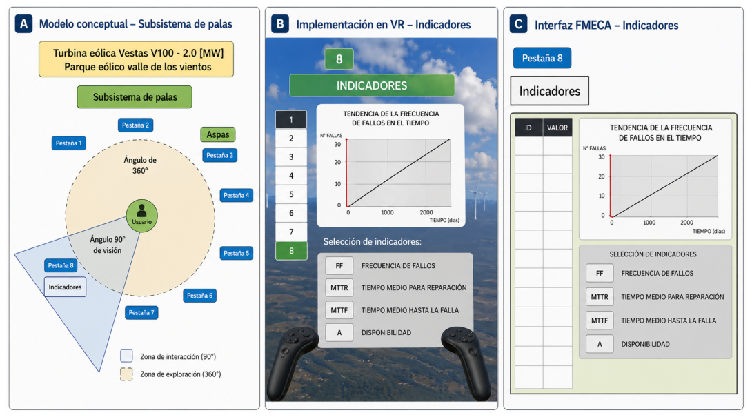
- First Stage: Definition of Basic Technical Maintenance Indicators (see Figure 14):
- Failure Frequency, FF (Reliability)
- Mean Time to Repair, MTTR (Maintainability)
- Mean Time to Failure, MTTF (Reliability)
- Availability (A)
- -
- Second Stage—Development of Probabilistic and Cost-Based Indicators:
- Reliability (Rt): Probability of failure, probability of no failure, time to failure, and failure frequency
- Maintainability (Mt): Probability of successful repair
- Failure Downtime Cost (FDC): Estimated cost due to system unavailability caused by failures
- -
- Expansion of Functional Scope: Extend the analysis to additional wind turbine subsystems and other critical industrial assets to broaden the technical coverage of the platform and validate its cross-sector applicability [48].
- -
- -
- -
- -
- Validation in Real Industrial Environments: Conduct pilot tests in collaboration with energy and industrial companies to gather practical feedback that supports further refinement and alignment of the tool with the needs of the productive sector [52].
8. Conclusions and Future Work
- A novel integration of reliability engineering and immersive technologies. This study demonstrates how FMECA and criticality analysis can be operationalized within a VR environment, enabling risk-based reasoning to be visualized and understood through interactive 3D scenarios.
- A replicable methodological workflow. The proposed framework provides a structured process for transforming analytical reliability outputs—operational context, failure modes, effects, criticality categories, and maintenance strategies—into immersive learning modules.
- Enhanced comprehension of complex failure mechanisms. Preliminary validation suggests that virtual reality-based visualization could help improve user understanding of interactions between subsystems, fault propagation, and the logic behind maintenance prioritization.
- A foundation for scalable Maintenance 4.0 solutions. The immersive VR-based training platform demonstrates feasibility at a development cost consistent with industrial training budgets and offers significant potential advantages in safety, learning efficiency, and standardization of training.
- Expanding the scope of analysis to include additional turbine subsystems such as gearbox, generator, pitch and yaw mechanisms, and hydraulic systems.
- Integrating real-time monitoring data (SCADA, IoT sensors, digital twins) to enhance dynamic failure visualization and support predictive maintenance scenarios.
- Developing multi-user collaborative features aligned with the Industrial Metaverse paradigm, enabling instructors and learners to interact within shared virtual environments.
- Enhancing user performance evaluation through quantitative analytics, including response times, mistake tracking, and scenario-based assessment.
- Incorporating full maintenance procedures such as inspection tasks, torque sequences, equipment replacement, and troubleshooting activities in interactive 3D workflows.
- Aligning the immersive platform with asset management standards, particularly ISO 55000 and the extended MMM framework, to provide a complete training solution across the asset lifecycle.
- Establish collaborations with academic institutions and industrial companies to implement technical training pilots using FMECA-VR-0.1 and gather feedback from both academic and production environments.
Supplementary Materials
Author Contributions
Funding
Institutional Review Board Statement
Informed Consent Statement
Data Availability Statement
Conflicts of Interest
Abbreviations
| VR | Virtual Reality |
| AR | Augmented Reality |
| XR | Extended Reality |
| FMECA | Failure Modes, Effects, and Criticality Analysis |
| QRCM | Qualitative Risk Criticality Matrix |
| MMM | Maintenance Management Model (INGEMAN) |
| CPS | Cyber-Physical System |
| IoT | Internet of Things |
| CBM | Condition-Based Maintenance |
| SCADA | Supervisory Control and Data Acquisition |
| IPO | Input–Process–Output |
| DFIG | Doubly-Fed Induction Generator |
| DT | Digital Twin |
| 3D | Three-Dimensional |
| 2D | Two-Dimensional |
| HSE/SHE | Safety, Health, and Environment |
| IP | Impact on Production |
| CDF | Cost of Direct Failure |
| USD | United States Dollars |
| CLP | Chilean Peso |
| O&M | Operations and Maintenance |
| PPE | Personal Protective Equipment |
| CAD | Computer-Aided Design |
| GPU | Graphics Processing Unit |
| SDK | Software Development Kit |
| FMECA-VR-0.1 | Failure Modes, Effects, and Criticality Analysis—Virtual Reliability-0.1 |
| RQCM | Risk Qualitative Criticality Matrix |
| MMM | Maintenance Management Model |
| FF | Failure Frequency |
| C | Consequences of failures |
| SHE | Safety, Health, and Environment |
| CDF | Costs Direct of Failure |
| IP | Impact of Production |
References
- Frank, A.G.; Dalenogare, L.S.; Ayala, N.F. Industry 4.0 technologies: Implementation patterns in manufacturing companies. Int. J. Prod. Econ. 2019, 210, 15–26. [Google Scholar] [CrossRef] [Scilit]
- Rußmann, M.; Lorenz, M.; Gerbert, P.; Waldner, M.; Justus, J.; Engel, P.; Harnisch, M. Industry 4.0: The Future of Productivity and Growth in Manufacturing Industries; Boston Consulting Group: Boston, MA, USA, 2015. [Google Scholar]
- De Carolis, A.; Macchi, M.; Negri, E.; Terzi, S. A maturity model for assessing the digital readiness of manufacturing companies. In IFIP International Conference on Advances in Production Management Systems; Springer: Berlin/Heidelberg, Germany, 2017; pp. 13–20. [Google Scholar] [CrossRef] [Scilit]
- Crespo Márquez, A. Driving the Introduction of Digital Technologies to Enhance the Maintenance Management Process and Framework. In Digital Maintenance Management; Springer Series in Reliability Engineering; Springer: Cham, Switzerland, 2022. [Google Scholar] [CrossRef] [Scilit]
- Lázaro Gaspar, J. El Fin de la Inercia: De la Revolución a la Protopía Digital. Origen, Evolución e Impacto del Nuevo Paradigma Tecnológico, Social y Empresarial. 2021. Available online: https://www.amazon.es/dp/B09GZPV3LS (accessed on 29 March 2026).
- Tao, F.; Zhang, H.; Liu, A.; Nee, A.Y.C. Digital twin in industry: State-of-the-art. IEEE Trans. Ind. Inf. 2019, 15, 2405–2415. [Google Scholar] [CrossRef] [Scilit]
- BMW Group. Predictive Maintenance: When a Machine Knows in Advance That Repairs Are Needed. PressClub Global, 2021. Available online: https://www.press.bmwgroup.com/global/article/detail/T0338859EN/predictive-maintenance%3A-when-a-machine-knows-in-advance-that-repairs-are-needed (accessed on 1 May 2026).
- Crespo Márquez, A. A Review of New Digital Technologies Impacting Maintenance Management. In Digital Maintenance Management; Springer: Cham, Switzerland, 2022; pp. 13–22. [Google Scholar] [CrossRef] [Scilit]
- Kawano, J. Condition-Based vs. Reliability-Centered Maintenance. VIDYATEC Blog. 2024. Available online: https://vidyatec.com/blog/condition-based-vs-reliability-centered-maintenance/ (accessed on 1 March 2026).
- Kumar, U.; Galar, D. Maintenance in the Era of Industry 4.0: Issues and Challenges. In Quality, IT and Business Operations; Kapur, P., Kumar, U., Verma, A., Eds.; Springer: Singapore, 2018; pp. 231–250. [Google Scholar] [CrossRef] [Scilit]
- Capgemini Research Institute. Gemelos Digitales: La Inteligencia Artificial Adaptada al Mundo Real; Capgemini: Paris, France, 2022; Available online: https://www.capgemini.com/es-es/investigacion/biblioteca-de-investigacion/gemelos-digitales/ (accessed on 1 May 2026).
- European Commission. Industry 5.0: Towards a Sustainable, Human-Centric and Resilient European Industry; Directorate-General for Research and Innovation: Brussels, Belgium, 2021. [Google Scholar] [CrossRef]
- Vinyard, J. The Future of Digital Twins & GenAI in The Energy Sector: From Overpromise to Powerhouse. GE Digital Blog. 2026. Available online: https://www.gevernova.com/software/blog/future-digital-twins-gen-ai-energy-sector?utm_source=chatgpt.com#introduction (accessed on 1 April 2026).
- Guiffo Kaigom, E. Potentials of the Metaverse for Robotized Applications in Industry 4.0 and Industry 5.0. Procedia Comput. Sci. 2024, 232, 1829–1838. [Google Scholar] [CrossRef] [Scilit]
- Jones, D.; Snider, C.; Nassehi, A.; Yon, J.; Hicks, B. Characterising the digital twin: A systematic literature review. CIRP J. Manuf. Sci. Technol. 2020, 29, 36–52. [Google Scholar] [CrossRef] [Scilit]
- Galar, D.; Kumar, U. Digital Twins: Definition, Implementation and Applications. In Advances in Risk-Informed Technologies; Varde, P.V., Kumar, M., Agarwal, M., Eds.; Springer: Singapore, 2024; pp. 79–106. [Google Scholar] [CrossRef] [Scilit]
- Parra, C.; Crespo, A. Ingeniería de Mantenimiento y Fiabilidad Aplicada en la Gestión de Activos, 2nd ed.; INGEMAN: Sevilla, Spain, 2024. [Google Scholar] [CrossRef]
- Crespo Márquez, A.; Moreu de León, P.; Gómez Fernández, J.F.; Parra Márquez, C.; López Campos, M. The maintenance management framework: A practical view. J. Qual. Maint. Eng. 2009, 15, 167–178. [Google Scholar] [CrossRef] [Scilit]
- Parra, C.; Morán, C.; Pizarro, F.; Duque, P.; Aránguiz, A.; González-Prida, V.; Parra, J. Implementation of the Asset Management, Operational Reliability and Maintenance Survey in Recycled Beverage Container Manufacturing Lines. Information 2024, 15, 784. [Google Scholar] [CrossRef] [Scilit]
- Parra, C.; González-Prida, V.; Candón, E.; De la Fuente, A.; Martínez-Galán, P.; Crespo, A. Integration of Asset Management Standard ISO 55000 with a Maintenance Management Model. In 14th WCEAM Proceedings; Springer: Cham, Switzerland, 2020; pp. 169–178. [Google Scholar] [CrossRef] [Scilit]
- Sun, Y.; Yang, Q.; Chen, J.; Li, H.; Wang, X.; Xu, D. Towards a Multi-Scenario Immersive Virtual Reality System for Maintenance inspection training of hot strip rolling mills. Virtual Real. 2025, 29, 86. [Google Scholar] [CrossRef] [Scilit]
- Di Pasquale, V.; Cutolo, P.; Esposito, C.; Franco, B.; Iannone, R.; Miranda, S. Virtual Reality for Training in Assembly and Disassembly Tasks: A Systematic Literature Review. Machines 2024, 12, 528. [Google Scholar] [CrossRef] [Scilit]
- Qawqzeh, Y.; Shraah, A.A.; Rizwan, A.; Sanchez-Chero, M.; Vallejos, L.; Shabaz, M. Exploring the Effectiveness of Virtual Reality-Based Training for Sustainable Health and Occupational Safety in Industry 4.0. Sci. Rep. 2025, 15, 28930. [Google Scholar] [CrossRef] [Scilit]
- Fry, A.; Fidan, I.; Wooldridge, E. Advancing Foundry Training Through Virtual Reality: A Low-Cost, Immersive Learning Environment. Inventions 2025, 10, 38. [Google Scholar] [CrossRef] [Scilit]
- Costa, A.; Miranda, J.; Dias, D.; Dinis, N.; Romero, L.; Faria, P.M. Smart Maintenance Solutions: AR- and VR-Enhanced Digital Twin Powered by FIWARE. Sensors 2025, 25, 845. [Google Scholar] [CrossRef] [Scilit]
- Coupry, C.; Richard, P.; Bigaud, D.; Noblecourt, S.; Baudry, D. The Value of Extended Reality Techniques to Improve Remote Collaborative Maintenance Operations: A User Study. In Proceedings of the 23rd International Conference on Construction Applications of Virtual Reality (CONVR 2023); Firenze University Press: Florence, Italy, 2023; pp. 23–33. [Google Scholar] [CrossRef] [Scilit]
- Matam, B.; Mann, A.; Studer, K.; Gabianelli, C.; Castelo, S.; Liu, J.; Silva, C.; Turakhia, D. CLAd-VR: Cognitive Load-Based Adaptive Training for Machining Tasks in Virtual Reality. In Proceedings of the IEEE International Symposium on Mixed and Augmented Reality Adjunct (ISMAR-Adjunct); IEEE: New York, NY, USA, 2025; pp. 432–435. [Google Scholar] [CrossRef] [Scilit]
- Strazzeri, I.; Notebaert, A.; Barros, C.; Quinten, J.; Demarbaix, A. Virtual Reality Integration for Enhanced Engineering Education and Experimentation: A Focus on Active Thermography. Computers 2024, 13, 199. [Google Scholar] [CrossRef] [Scilit]
- Akpan, I.J.; Offodile, O.F. The Role of Virtual Reality Simulation in Manufacturing in Industry 4.0. Systems 2024, 12, 26. [Google Scholar] [CrossRef] [Scilit]
- Spadoni, E.; Bordegoni, M.; Carulli, M.; Ferrise, F. Extended Reality in Industry: Past, Present and Future Perspectives. Proc. Des. Soc. 2023, 3, 1845–1854. [Google Scholar] [CrossRef] [Scilit]
- Yanytska, L. The rise of human-centric manufacturing in the industry 5.0 era. Int. J. Adv. Manuf. Technol. 2025, 139, 5067–5077. [Google Scholar] [CrossRef] [Scilit]
- Breitkreuz, D.; Müller, M.; Stegelmeyer, D.; Mishra, R. Augmented Reality Remote Maintenance in Industry: A Systematic Literature Review. In Extended Reality (XR Salento 2022); De Paolis, L.T., Arpaia, P., Sacco, M., Eds.; Lecture Notes in Computer Science; Springer: Cham, Switzerland, 2022; Volume 13446, pp. 287–306. [Google Scholar] [CrossRef] [Scilit]
- ISO 14224:2016; Petroleum, Petrochemical and Natural Gas Industries—Collection and Exchange of Reliability and Maintenance Data for Equipment. International Organization for Standardization: Geneva, Switzerland, 2016.
- Parra, C.; Crespo, A.; Parra, J.; Kristjanpoller, F.; Tino, G.; Viveros, P.; González-Prida, V. Metodología Básica de Análisis de Riesgo para Evaluar la Criticidad de Activos Industriales: Caso de Estudio en una Línea de Manufactura de Envases Biodegradables; Informe Técnico; INGEMAN: Sevilla, España, 2021; Volume 12. [Google Scholar] [CrossRef]
- ISO 55000:2014; Asset Management—Overview, Principles and Terminology. International Organization for Standardization: Geneva, Switzerland, 2014. Available online: https://www.iso.org/obp/ui/#iso:std:iso:55000:ed-1:v2:en (accessed on 1 March 2026).
- Comisión Nacional de Energía (CNE). Informe Anual de Generación Renovable en Chile. 2022. Available online: https://www.cne.cl (accessed on 1 March 2026).
- Vestas Wind Systems A/S. V100-2.0 MW Technical Specification Sheet. 2021. Available online: https://www.vestas.com (accessed on 1 May 2026).
- Siemens Mobility. Digital Transformation for Sustainable Mobility with Railigent X. 2024. Available online: https://www.mobility.siemens.com/global/en/portfolio/digital-solutions-software/digital-services/railigent-x.html (accessed on 1 May 2026).
- GE Vernova Digital. Process & Asset Predictive Analytics. 2026. Available online: https://www.gevernova.com/software/products/predictive-analytics (accessed on 1 March 2026).
- Ukoba, K.; Olatunji, K.O.; Adeoye, E.; Jen, T.-C.; Madyira, D.M. Optimizing renewable energy systems through artificial intelligence: Review and future prospects. Energy Environ. 2024, 35, 3833–3879. [Google Scholar] [CrossRef] [Scilit]
- Caterpillar Inc. Enhancing Quality and Post-Sales Reliability with Real-Time Monitoring and ISO 9001 Standards. 2023. Available online: https://www.cat.com/en_US/by-industry/electric-power/product-support/cat-connect.html (accessed on 1 March 2026).
- TurboSquid. Wind Turbine 3D Model. Available online: https://www.turbosquid.com/es/3d-models/wind-turbine-3d-model-1241219 (accessed on 1 March 2026).
- Meta Platforms. Meta Quest 2 Specifications. 2023. Available online: https://www.meta.com/quest/products/quest-2/ (accessed on 1 May 2026).
- LinkedIn. Video de Demostración de la Herramienta FMECA–VR 0.1. 2024. Available online: https://www.linkedin.com/feed/update/urn:li:activity:7200352283866349568/ (accessed on 1 May 2026).
- Mu, H.; He, F.; Yuan, L.; Commins, P.; Wang, H.; Pan, Z. Toward a Smart Wire Arc Additive Manufacturing System: A Review on Current Developments and a Framework of Digital Twin. J. Manuf. Syst. 2023, 67, 174–189. [Google Scholar] [CrossRef] [Scilit]
- Galar, D.; Kumar, U. E-Maintenance: Essential Electronic Tools for Efficiency; Academic Press: Cambridge, MA, USA, 2017. [Google Scholar]
- Jardine, A.K.S.; Lin, D.; Banjevic, D. A Review on Machinery Diagnostics and Prognostics Implementing Condition-Based Maintenance. Mech. Syst. Signal Process. 2006, 20, 1483–1510. [Google Scholar] [CrossRef] [Scilit]
- García-Peñalvo, F.J.; Conde, M.Á. The impact of a mobile personal learning environment in different educational contexts. Univ. Access Inf. Soc. 2015, 14, 375–387. [Google Scholar] [CrossRef] [Scilit]
- Wang, P.; Wu, P.; Wang, J.; Chi, H.L.; Wang, X. A Critical Review of the Use of Virtual Reality in Construction Engineering Education and Training. Int. J. Environ. Res. Public Health 2018, 15, 1204. [Google Scholar] [CrossRef] [Scilit]
- Uhlemann, T.H.J.; Lehmann, C.; Steinhilper, R. The Digital Twin: Realizing the Cyber-Physical Production System for Industry 4.0. Procedia CIRP 2017, 61, 335–340. [Google Scholar] [CrossRef] [Scilit]
- González-Prida, V.; Parra Márquez, C.; Viveros Gunckel, P.; Rodríguez, F.K.; Crespo Márquez, A. Digital Transformation in Aftersales and Warranty Management: A Review of Advanced Technologies in I4.0. Algorithms 2025, 18, 231. [Google Scholar] [CrossRef] [Scilit]
- IEEE Std 1589-2020; IEEE Standard for Augmented Reality Learning Experience Model (ARLEM). IEEE: Piscataway, NJ, USA, 2020. Available online: https://standards.ieee.org/ieee/1589/6073/ (accessed on 8 May 2026).
- Gavish, N.; Gutiérrez, T.; Webel, S.; Rodríguez, J.; Peveri, M.; Bockholt, U.; Tecchia, F. Evaluating Virtual Reality and Augmented Reality Training for Industrial Maintenance and Assembly Tasks. Interact. Learn. Environ. 2015, 23, 778–798. [Google Scholar] [CrossRef] [Scilit]
- Nayak, A.; Patnaik, A.; Satpathy, I.; Patnaik, B.C.; Gupta, S. Exploring the Benefits of Virtual Reality (VR) in Manufacturing Training: A Comprehensive Overview. In Emerging Technologies in Digital Manufacturing and Smart Factories; Hassan, A., Dutta, P., Gupta, S., Mattar, E., Singh, S., Eds.; IGI Global: Hershey, PA, USA, 2024; pp. 205–221. [Google Scholar] [CrossRef] [Scilit]
- Soliman, M.; Pesyridis, A.; Dalaymani-Zad, D.; Gronfula, M.; Kourmpetis, M. The Application of Virtual Reality in Engineering Education. Appl. Sci. 2021, 11, 2879. [Google Scholar] [CrossRef] [Scilit]
- Bęś, P.; Strzałkowski, P. Analysis of the Effectiveness of Safety Training Methods. Sustainability 2024, 16, 2732. [Google Scholar] [CrossRef] [Scilit]
- Scorgie, D.; Feng, Z.; Paes, D.; Parisi, F.; Yiu, T.W.; Lovreglio, R. Virtual Reality for Safety Training: A Systematic Literature Reviewand Meta-Analysis. Saf. Sci. 2024, 171, 106372. [Google Scholar] [CrossRef] [Scilit]



| Reference | Main Contribution | Application Area |
|---|---|---|
| Sun et al. (2025) [21] | Proposes a multi-scenario immersive VR system for maintenance inspection training in steel rolling mills. | Industrial VR training; maintenance inspection. |
| Di Pasquale et al. (2024) [22] | Systematic review showing the effectiveness of VR for assembly and disassembly training. | VR for technical training; systematic literature review. |
| Qawqzeh et al. (2025) [23] | Demonstrates the effectiveness of VR-based safety training for industrial workers through controlled experimentation. | Occupational safety; VR human-performance evaluation. |
| Fry et al. (2025) [24] | Develops a VR training platform for foundry operations, improving understanding and task execution training—framework developed for the Tennessee Tech University (TTU) Foundry. | Advanced industrial VR education. |
| Costa et al. (2025) [25] | Integrates Digital Twins with VR/AR and IoT using FIWARE; demonstrates real-time industrial monitoring. | Digital Twin applications; Industry 4.0. |
| Coupry et al. (2023) [26] | Evaluates XR for remote collaborative maintenance tasks, showing improvements in communication and efficiency. | XR for remote collaboration; maintenance operations. |
| Matam et al. (2025) [27] | Introduces CLAd-Vr system’s architecture, including the EEG sensing hardware, real-time inference model, and adaptive VR interface. | Adaptive VR learning; cognitive engineering. |
| Strazzeri et al. (2024) [28] | Presents VR integration for engineering education and industrial maintenance training (case study: thermography for a carbon fiber plate in the aerospace domain). | Engineering VR education; maintenance instruction. |
| Akpan and Offodile (2024) [29] | This study undertakes a science mapping of research on the role of Virtual Reality Simulation (VRSIM) in manufacturing in the 4IR. | Predictive maintenance; Digital Twins; manufacturing sector. |
| Spadoni et al. (2023) [30] | Reviews current trends of XR in advanced manufacturing systems. | XR in manufacturing; Industry 4.0. |
| Yanytska (2025) [31] | Defines the Industry 5.0 paradigm with emphasis on human-centered manufacturing and resilience. | Industry 5.0; human–machine interaction. |
| Breitkreuz et al. (2022) [32] | Systematic review of AR applications in industrial maintenance and proposes a research agenda. | AR in maintenance, Maintenance 4.0 |
| Subsystems | SHA | IP | CDF | TC: Total | F: | Risk | Criticality Level |
|---|---|---|---|---|---|---|---|
| Consequences | Frequency | (TC × F) | |||||
| Blade System | 5 | 4 | 4 | 13 | 5 | 65 | Very High Criticality |
| Electric Generator | 4 | 5 | 4 | 13 | 5 | 65 | Very High Criticality |
| Main Shaft Assembly | 5 | 5 | 5 | 15 | 4 | 60 | Very High Criticality |
| Tower | 5 | 4 | 3 | 12 | 4 | 48 | High Criticality |
| Gearbox (Transmission) | 2 | 5 | 4 | 11 | 4 | 44 | High Criticality |
| Transformer | 3 | 4 | 3 | 10 | 4 | 40 | High Criticality |
| Electrical Panel | 3 | 4 | 3 | 10 | 2 | 20 | Medium Criticality |
| Hydraulic System | 2 | 4 | 3 | 9 | 2 | 18 | Low Criticality |
| Anemometer and Wind Vane | 3 | 3 | 2 | 8 | 2 | 16 | Low Criticality |
| Frequency Converter | 3 | 3 | 3 | 9 | 1 | 9 | Low Criticality |
| Yaw System | 2 | 3 | 3 | 8 | 1 | 8 | Low Criticality |
| Control and Communication | 1 | 3 | 2 | 6 | 1 | 6 | Low Criticality |
| Physical Failure | SHA | IP | CDF | TC: Total | F: | Risk | Criticality Level |
|---|---|---|---|---|---|---|---|
| Modes | Consequences | Frequency | (TC × F) | ||||
| Blades | 5 | 5 | 5 | 15 | 4 | 60 | Very High Criticality |
| Nose Cone | 3 | 5 | 5 | 13 | 3 | 39 | Medium Criticality |
| Hub | 2 | 5 | 5 | 12 | 3 | 36 | Medium Criticality |
| Subsystem | Function | Physical Failure Modes (Components) | Failure Effect | Criticality Level | Value | Probable Causes |
|---|---|---|---|---|---|---|
| Blades | Capture wind energy and convert it into mechanical energy to drive the wind turbine rotor. | Blade | Loss of aerodynamic capability. | Very High Criticality | 60 | Blades showing buckling |
| Blade structure with cracks | ||||||
| Blade structure with delamination | ||||||
| Blades showing bending | ||||||
| Nose | Loss of aerodynamic capability. | Medium Criticality | 39 | Nose structure with cracks | ||
| Impact damage from foreign objects on nose | ||||||
| Nose looseness due to poor installation | ||||||
| Presence of corrosion on nose | ||||||
| Hub | Loss of aerodynamic capability. | Medium Criticality | 36 | Hub structure with cracks | ||
| Hub with misalignment | ||||||
| Malfunction in hub orientation mechanism | ||||||
| Presence of corrosion on hub |
| Subsystem | Physical Failure Mode (Components)/Ranking | Probable Causes | Type of Maintenance | Maintenance Task | Application Frequency | Responsible Specialist | Maintenance Plan Costs (USD/year) | Annual Maintenance Hours |
|---|---|---|---|---|---|---|---|---|
| Blades | Blades/Very High Criticality | Blades showing buckling | Condition-Based Maintenance | Thermographic winding inspection | Monthly | Electromechanical Technician | $5000 | 12 |
| Condition-Based Maintenance | Ultrasound Inspection | Monthly | Electromechanical Technician | 12 | ||||
| Condition-Based Maintenance | X-ray Inspection | Quarterly | Electromechanical Technician | 6 | ||||
| Blade structure with cracks | Condition-Based Maintenance | Thermographic winding inspection | Monthly | Electromechanical Technician | $5000 | 12 | ||
| Condition-Based Maintenance | Ultrasound Inspection | Monthly | Electromechanical Technician | 12 | ||||
| Condition-Based Maintenance | X-ray Inspection | Quarterly | Electromechanical Technician | 6 | ||||
| Blade structure with delamination | Condition-Based Maintenance | Thermographic winding inspection | Monthly | Electromechanical Technician | $5000 | 12 | ||
| Condition-Based Maintenance | Ultrasound Inspection | Monthly | Electromechanical Technician | 12 | ||||
| Condition-Based Maintenance | X-ray Inspection | Quarterly | Electromechanical Technician | 6 | ||||
| Blades showing bending | Condition-Based Maintenance | Thermographic winding inspection | Monthly | Electromechanical Technician | $5000 | 12 | ||
| Condition-Based Maintenance | Ultrasound Inspection | Monthly | Electromechanical Technician | 12 | ||||
| Condition-Based Maintenance | X-ray Inspection | Quarterly | Electromechanical Technician | 6 | ||||
| Nose | Nose/Medium Criticality | Nose structure with cracks | Condition-Based Maintenance | Thermographic winding inspection | Monthly | Electromechanical Technician | $5000 | 12 |
| Condition-Based Maintenance | Ultrasound Inspection | Monthly | Electromechanical Technician | 12 | ||||
| Impact damage from foreign objects on nose | Condition-Based Maintenance | X-ray Inspection | Quarterly | Electromechanical Technician | 6 | |||
| Condition-Based Maintenance | Thermographic winding inspection | Monthly | Electromechanical Technician | $5000 | 12 | |||
| Condition-Based Maintenance | Ultrasound Inspection | Monthly | Electromechanical Technician | 12 | ||||
| Condition-Based Maintenance | X-ray Inspection | Quarterly | Electromechanical Technician | 6 | ||||
| Nose looseness due to poor installation | Condition-Based Maintenance | Thermographic winding inspection | Monthly | Electromechanical Technician | $5000 | 12 | ||
| Condition-Based Maintenance | Ultrasound Inspection | Monthly | Electromechanical Technician | 12 | ||||
| Condition-Based Maintenance | X-ray Inspection | Quarterly | Electromechanical Technician | 6 | ||||
| Presence of corrosion on the nose | Condition-Based Maintenance | Thermographic winding inspection | Monthly | Electromechanical Technician | $5000 | 12 | ||
| Condition-Based Maintenance | Ultrasound Inspection | Monthly | Electromechanical Technician | 12 | ||||
| Condition-Based Maintenance | X-ray Inspection | Quarterly | Electromechanical Technician | 6 | ||||
| Hub | Hub/Medium Criticality | Hub structure with cracks | Condition-Based Maintenance | Thermographic winding inspection | Monthly | Electromechanical Technician | $5000 | 12 |
| Condition-Based Maintenance | Ultrasound Inspection | Monthly | Electromechanical Technician | 12 | ||||
| Condition-Based Maintenance | X-ray Inspection | Quarterly | Electromechanical Technician | 6 | ||||
| Hub with misalignment | Condition-Based Maintenance | Thermographic winding inspection | Monthly | Electromechanical Technician | $5000 | 12 | ||
| Condition-Based Maintenance | Ultrasound Inspection | Monthly | Electromechanical Technician | 12 | ||||
| Condition-Based Maintenance | X-ray Inspection | Quarterly | Electromechanical Technician | 6 | ||||
| Malfunction in hub orientation mechanism | Condition-Based Maintenance | Thermographic winding inspection | Monthly | Electromechanical Technician | $5000 | 12 | ||
| Condition-Based Maintenance | Ultrasound Inspection | Monthly | Electromechanical Technician | 12 | ||||
| Condition-Based Maintenance | X-ray Inspection | Quarterly | Electromechanical Technician | 6 | ||||
| Presence of corrosion on the hub | Condition-Based Maintenance | Thermographic winding inspection | Monthly | Electromechanical Technician | $5000 | 12 | ||
| Condition-Based Maintenance | Ultrasound Inspection | Monthly | Electromechanical Technician | 12 | ||||
| Condition-Based Maintenance | X-ray Inspection | Quarterly | Electromechanical Technician | 6 |
| General Budget | |||||
|---|---|---|---|---|---|
| Labor Costs | |||||
| Code | Subsystem | Unit | Hours | Unit Price (CLP) | Subtotal (CLP) |
| P1 | Blades | h | 27 | $17,046 | $460,250 |
| P2 | Control and Communication | h | 63 | $17,046 | $1,073,916 |
| P3 | Electrical Panel | h | 63 | $17,046 | $1,073,916 |
| P4 | Transformer | h | 63 | $17,046 | $1,073,916 |
| P5 | Frequency Converter | h | 63 | $17,046 | $1,073,916 |
| P6 | Electric Generator | h | 63 | $17,046 | $1,073,916 |
| P7 | Tower | h | 63 | $17,046 | $1,073,916 |
| P8 | Yaw System | h | 63 | $17,046 | $1,073,916 |
| P9 | Anemometer and Wind Vane | h | 63 | $17,046 | $1,073,916 |
| P10 | Gearbox | h | 63 | $17,046 | $1,073,916 |
| P11 | Main Shaft Assembly | h | 63 | $17,046 | $1,073,916 |
| P12 | Hub | h | 63 | $17,046 | $1,073,916 |
| P13 | Pitch Control System | h | 63 | $17,046 | $1,073,916 |
| P14 | Hydraulic System | h | 63 | $17,046 | $1,073,916 |
| Total (labor) (CLP) $14,421,156 | |||||
| Materials Costs | |||||
| Item | Component | Unit | Quantity | Unit Price (CLP) | Subtotal (CLP) |
| 1 | Oculus Quest 2 VR Headsets | Und | 3 | $409,052 | $1,227,156 |
| 2 | Laptop Cooler Base | Und | 3 | $20,000 | $60,000 |
| 3 | Oculus Link Cable | Und | 1 | $16,990 | $16,990 |
| 4 | HP Victus Notebook (RTX, 8 GB RAM) | Und | 3 | $749,990 | $2,249,970 |
| 5 | 3D Model of Wind Turbine | Und | 1 | $224,315 | $224,315 |
| Total (material): CLP $18,199,587 | |||||
| General Expenses (20%): CLP $3,639,918 | |||||
| Profit Margin (15%): CLP $2,729,938 | |||||
| Net Total: CLP $24,569,443 | |||||
| VAT (19%): CLP $4,669,194 | |||||
| Final Total: CLP $29,237,637 | |||||
| Project Management Costs | |||
|---|---|---|---|
| Professional | Quantity | Monthly Salary (CLP) | 5-Month Cost (CLP) |
| Maintenance Engineer | 1 | $1,300,000 | $6,500,000 |
| Technician | 1 | $850,000 | $4,250,000 |
| Programmer | 1 | $1,500,000 | $7,500,000 |
| Subtotal (Net): CLP $18,250,000 | |||
| VAT (19%): CLP $3,467,500 | |||
| Total Project Management Cost: CLP $21,717,500 | |||
Disclaimer/Publisher’s Note: The statements, opinions and data contained in all publications are solely those of the individual author(s) and contributor(s) and not of MDPI and/or the editor(s). MDPI and/or the editor(s) disclaim responsibility for any injury to people or property resulting from any ideas, methods, instructions or products referred to in the content. |
© 2026 by the authors. Licensee MDPI, Basel, Switzerland. This article is an open access article distributed under the terms and conditions of the Creative Commons Attribution (CC BY) license.
Share and Cite
Parra, C.; Ognio, J.; Duque, P.; Pizarro, F.; Aránguiz, A.; González-Prida, V.; Crespo, A.; Parra, J. Development of an Immersive VR-Based Training Platform Integrating FMECA for Wind Turbine Maintenance: FMECA-VR-0.1 Prototype. Appl. Sci. 2026, 16, 4909. https://doi.org/10.3390/app16104909
Parra C, Ognio J, Duque P, Pizarro F, Aránguiz A, González-Prida V, Crespo A, Parra J. Development of an Immersive VR-Based Training Platform Integrating FMECA for Wind Turbine Maintenance: FMECA-VR-0.1 Prototype. Applied Sciences. 2026; 16(10):4909. https://doi.org/10.3390/app16104909
Chicago/Turabian StyleParra, Carlos, José Ognio, Pablo Duque, Félix Pizarro, Andrés Aránguiz, Vicente González-Prida, Adolfo Crespo, and Jorge Parra. 2026. "Development of an Immersive VR-Based Training Platform Integrating FMECA for Wind Turbine Maintenance: FMECA-VR-0.1 Prototype" Applied Sciences 16, no. 10: 4909. https://doi.org/10.3390/app16104909
APA StyleParra, C., Ognio, J., Duque, P., Pizarro, F., Aránguiz, A., González-Prida, V., Crespo, A., & Parra, J. (2026). Development of an Immersive VR-Based Training Platform Integrating FMECA for Wind Turbine Maintenance: FMECA-VR-0.1 Prototype. Applied Sciences, 16(10), 4909. https://doi.org/10.3390/app16104909