Article

Stability of High Stopes and Optimization of Combined Mining: A Case Study of the Dongguashan Copper Mine


1
School of Resources and Safety Engineering, Central South University, Changsha 410083, China
2
Guangdong Hongda Holdings Group Co., Ltd., Guangzhou 510623, China
3
School of Mechanics and Safety Engineering, Zhengzhou University, Zhengzhou 450001, China
*
Author to whom correspondence should be addressed.
Appl. Sci. 2026, 16(10), 4738; https://doi.org/10.3390/app16104738
Submission received: 11 April 2026 / Revised: 28 April 2026 / Accepted: 29 April 2026 / Published: 10 May 2026

Abstract

To address the issues of severe goaf collapse, difficulties in secondary extraction, and insufficient pillar stability encountered during the mining of high stopes north of Line 60 at the Dongguashan Copper Mine, this paper takes these high stopes as the research object. Based on an analysis of the engineering geological conditions, goaf failure characteristics, and current mining status in this area, a study on pillar stability and the mechanical behavior of combined mining is conducted. Given the susceptibility of pillars with high aspect ratios to bending instability, the secondary extraction pillar is simplified as a rod with fixed ends. A mechanical model for the triangular pillar’s stability is established, the critical instability equation is derived, and the influence of the reserved width on the pillar’s critical stress and safety factor is analyzed. Subsequently, based on the critical instability equation, the relationship between the reserved pillar width and critical stress is obtained to optimize the pillar dimensions. Simultaneously, to mitigate the adverse effects of primary stope collapse on secondary extraction, optimized schemes such as three-stope combined mining and two-stope combined mining are proposed. A mechanical model for combined mining is established based on the Protodyakonov’s arch theory to analyze the stress distribution characteristics of the surrounding rock in the goaf under different mining schemes. The calculated stress of the original rectangular pillar is 29.01 MPa. When the reserved width exceeds 4 m, the pillar safety factor becomes greater than 1.6, satisfying the stability requirement. In addition, three combined mining schemes were compared using Protodyakonov’s arch theory. The goaf spans of the three schemes are 40 m, 26.6 m, and 36 m, respectively. The results indicate that the two-stope combined mining scheme transfers the main roof load to the adjacent ore body and backfill, reducing the load borne by the barrier pillar and providing a better balance between safety and production efficiency. The proposed framework, integrating field goaf detection, pillar buckling analysis, reserved-width optimization, and combined mining comparison, provides a practical method for the stability control and secondary recovery of deep high stopes.

1. Research Status

In mining engineering, pillars are columnar structures of ore retained to support the goaf and the overlying strata, maintaining roadway stability. Through reasonable pillar layout, surface subsidence and surrounding rock deformation in the goaf can be effectively controlled, reducing geological disaster risks [1,2]. Optimization of pillar design can balance safety and ore recovery rate, avoiding resource waste caused by excessive retention or over-extraction. Their layout and dimensions directly affect the mining sequence, equipment arrangement, and backfilling scheme, serving as an important basis for mining method design [3,4]. If pillars become unstable, it may lead to goaf collapse, thereby endangering personnel safety and causing safety accidents [5,6,7,8]. Rockburst is one of the typical hazards in deep mining [9,10], and pillar design is the primary and most fundamental component of the rockburst prevention and control system. Therefore, research on pillar stability can effectively reduce accident risks and ensure the safety of mine operations [11,12,13].
The main research methods for pillars include traditional empirical methods, numerical simulation methods (finite element and finite difference), machine learning methods, etc. [14,15,16]. Empirical methods, based on long-term practical experience, can quickly assess pillar stability, providing certain engineering guidance, especially when detailed data is lacking. The Finite Element Method (FEM) can simulate complex geological conditions and pillar structures, handling various issues such as non-linearity, material mechanics, and boundary conditions [17,18]; it allows for model calibration based on field data, yielding simulation results closer to reality. The Finite Difference Method (FDM) has a simpler solution process than FEM and higher computational efficiency, making it suitable for handling linear or near-linear problems and applicable to relatively simple pillar stability issues [19,20]. Machine learning models (Random Forest [21], Support Vector Machine [22,23], and ANN [24]) identify patterns in pillar stability through big data analysis, offering good adaptability and scalability; they can continuously optimize models as data increases, achieving high prediction accuracy, especially in mines with substantial accumulated data [25,26,27]. In recent years, improved research methods for pillar stability have become increasingly popular among scholars. Cai et al. [28] proposed a novel Feature Fusion Learning (FFL) framework that integrates feature fusion, machine learning (ML) models, and category voting to predict underground pillar stability status. Zvarivadza, T. et al. [29] proposed an advanced framework for determining pillar stress, integrating analytical, numerical simulation, machine learning, and geostatistical techniques to enhance pillar stress prediction accuracy. Wang et al. [30] conducted research combining theoretical analysis, numerical simulation, and field application, establishing a mechanical model for a roof–pillar cooperative bearing structure and deriving an analytical solution for roof bending stress. Cortez et al. [31] proposed a comprehensive parametric analysis implemented in COMSOL Multiphysics to quantify the influence of dike geometry, stiffness contrast, and contact strength on stress distribution within rock pillars. Maina, D. [32] developed and implemented a three-dimensional modified Hoek–Brown (HB) constitutive model incorporating the intermediate principal stress component into the numerical simulation tool FLAC3D, applying a strength reduction technique to determine a more accurate pillar safety factor. Hao, H. and Li et al. [33] developed a refined numerical simulation framework based on the UDEC-Trigon discrete element method. Utilizing representative engineering conditions from western China, the framework reproduces roof collapse behavior and evaluates coal pillar stability with high fidelity. This framework integrates a fracture-controlled calibration procedure and explicitly captures the progressive failure mechanisms governing pillar behavior under deep mining conditions.
However, empirical methods lack precise predictive capability for high-aspect-ratio pillars and complex geology. The finite element method requires substantial computational effort and relies heavily on rock mass parameters, with potential deviations in local nonlinear effects. The finite difference method is suitable for linear problems but struggles to reflect local buckling and multi-pillar interaction in high stopes. Machine learning methods depend on large amounts of historical data and struggle to handle atypical or extreme collapse events, while also having poor interpretability. Even comprehensive methods face issues such as computational complexity, time-consuming calibration, and local errors. In high stopes with significant height and complex geological environments, pillar design and stability research become more challenging. The stress distribution in high stope pillars is highly complex, with nonlinear stress variations. Existing mechanical models cannot accurately describe the stress distribution and deformation behavior of pillars, especially under heterogeneous rock mass and complex geological conditions, making stopes prone to collapse and instability. The safe and efficient extraction of high stopes faces severe challenges, significantly constraining resource recovery efficiency and mining safety [34]. Based on this, this paper conducts theoretical research on pillar stability and roof mechanical behavior for the high stopes north of Line 60 at the Dongguashan Copper Mine, proposing a triangular pillar. By establishing a mechanical model for the pillar with fixed-end constraints, deriving its critical instability equation, analyzing the relationship between reserved width and critical stress, optimizing pillar dimensions, and analyzing several combined mining layout schemes, this study provides a basis for the rational layout of extraction pillars. The novelty of this study lies in three aspects. First, unlike conventional pillar stability studies that mainly rely on empirical estimation or numerical simulation, this study develops an analytical buckling model specifically for high-aspect-ratio secondary pillars in deep high stopes. Second, the collapse morphology obtained from field goaf detection is linked with the design of a triangular reserved pillar and a hexagonal secondary pillar section, allowing the pillar geometry to be optimized according to actual failure characteristics. Third, Protodyakonov’s arch theory is introduced to compare different combined mining layouts, so that pillar stability and mining efficiency can be evaluated within a unified mechanical framework. Therefore, this study provides not only a case-specific design recommendation for Dongguashan Copper Mine, but also a reproducible analytical procedure for similar deep metal mines with high stopes and difficult secondary extraction conditions.

2. Project Overview

The Dongguashan deposit is a deep-seated deposit in the Shizishan mining area. The main ore body is 1810 m long, with an average width of 500 m, buried at depths below −690 to −1000 m, and contains over 1 million tons of copper metal, making it an extra-large skarn-type copper deposit. The ore body strikes NE35–40°, with limbs dipping southeast and northwest, respectively. The dip angle in the middle section is relatively gentle, while the dip angle on the limbs increases to approximately 30–40°. The ore body roof consists of marble, and the floor consists of siltstone and quartz diorite. The ore-bearing rock mass (ore body) is mainly composed of copper-bearing skarn, copper-bearing serpentinite, and copper-bearing magnetite.
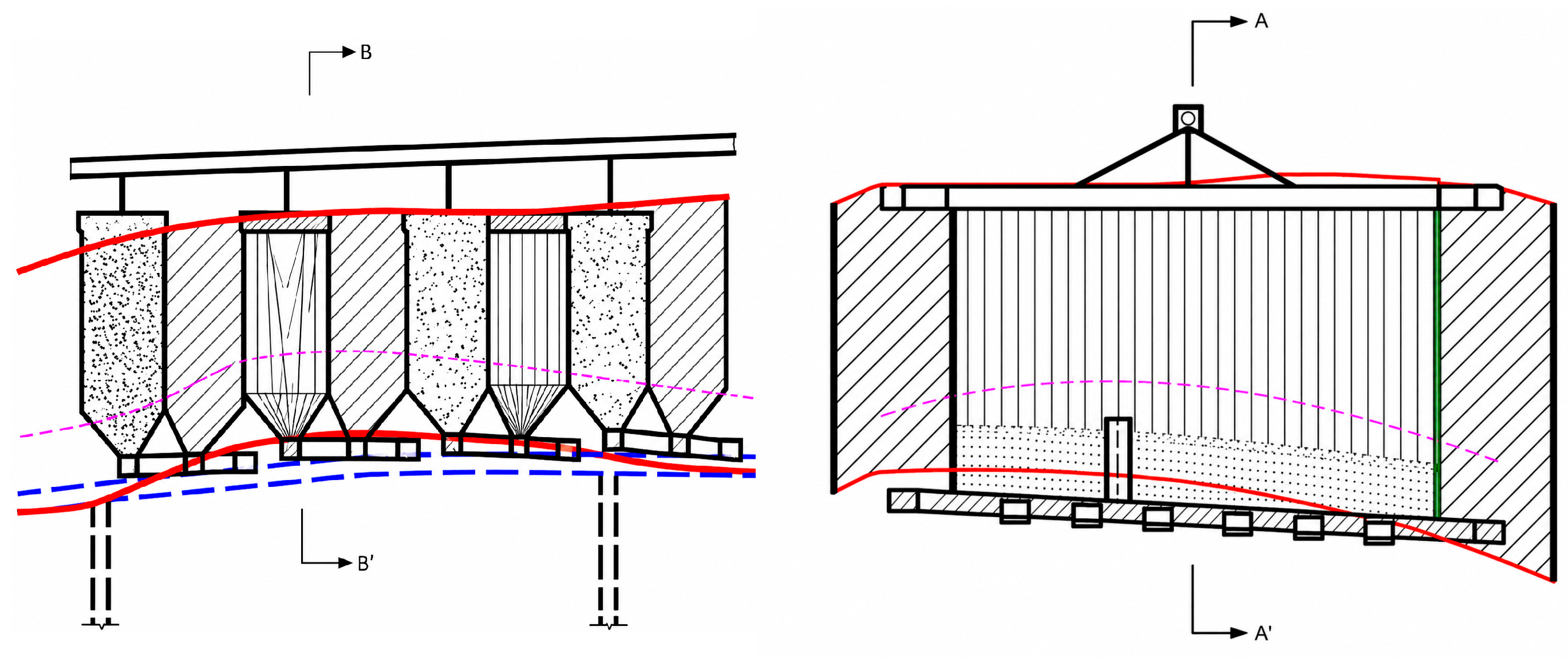
The Dongguashan deposit adopts a non-pillar continuous mining, sublevel open stoping with subsequent backfill mining method (Figure 1). The deposit is first divided into panels, and each panel is further divided into stopes for stepwise extraction. Each panel is 100 m long, with panel pillars left between panels, which are 18 m wide. Within a panel, both ore room and ore pillar stopes are divided with a width of 18 m. Ore room stopes are primary stopes, which are backfilled with cemented fill after extraction. Ore pillar stopes are secondary stopes, which are backfilled with low-strength cemented fill after extraction. The panel barrier pillars are extracted in the third step. This mining method effectively addresses the challenge of extracting gently inclined, thick and large ore bodies at Dongguashan. However, the stepwise extraction also presents issues such as significant dilution and loss in some pillar stopes during extraction, as well as extensive support work requirements. Stope blasting consists of medium-depth hole blasting in the bottom structure and large-diameter hole blasting in the upper drilling chamber.
As mining progresses, the primary and secondary stopes have been extracted to the north of Line 60. The stopes north of Line 60 have a large height, and currently, these stopes undertake the main production tasks of the Dongguashan deposit. Compared with the stopes south of Line 60, the geological conditions north of Line 60 are more complex, with extensively developed fracture zones and particularly prominent fold structures. The fault system in this area results from the superposition of near-east–west and near-north–south fault zones formed in different periods, exhibiting a typical “grid-like” structural characteristic of the mining area. Due to the pronounced fold structures, substantial energy has accumulated within the ore rock. When stoping advances into this area, the release of this energy significantly weakens the stability of the ore rock. In addition, the burial depth of the Dongguashan deposit exceeds 1000 m, resulting in inherently high in situ stress levels, and the ground pressure transfer effect further promotes the concentration of in situ stress in local areas. Meanwhile, the significant height of the stopes north of Line 60 increases the lateral exposure area of the goaf, and the aspect ratio of the pillars increases accordingly, thereby reducing the overall stability of the goaf and increasing the likelihood of stope collapse.
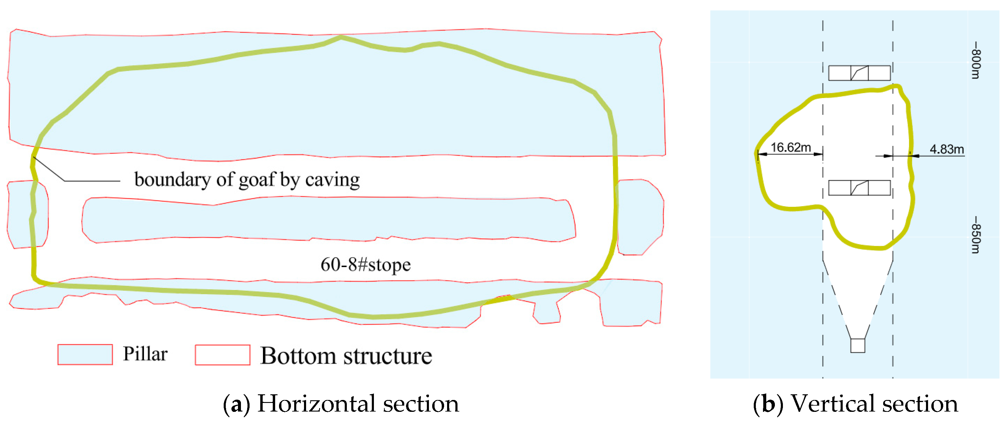
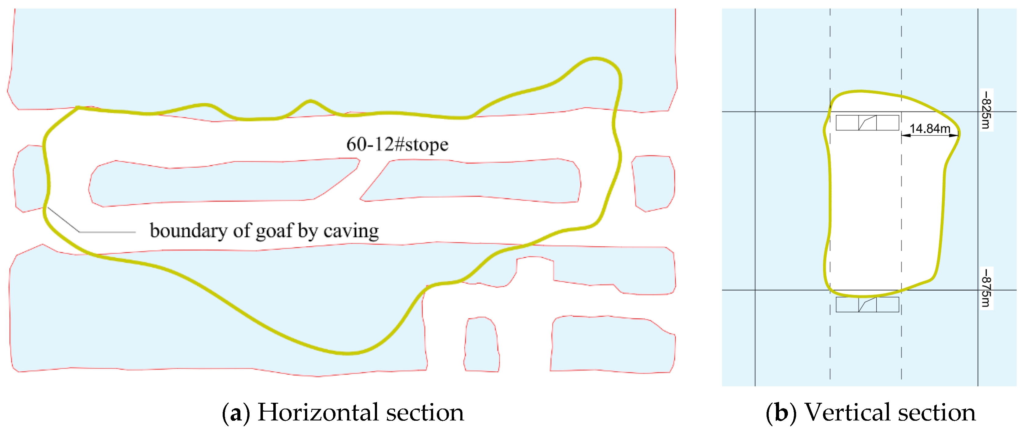
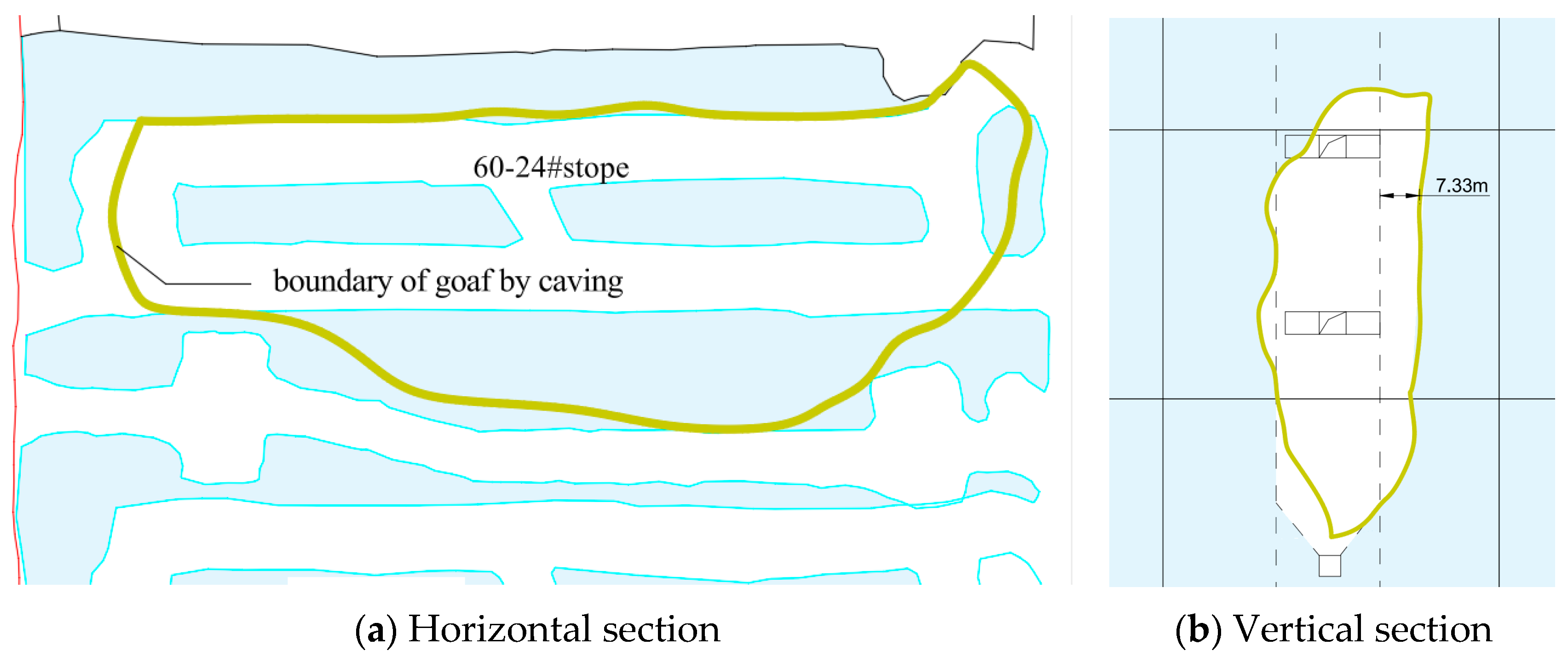
Based on previous extraction conditions, some primary high stopes north of Line 60 have experienced severe collapse (as shown in Figure 2, Figure 3 and Figure 4). On one hand, this increases the difficulty of secondary extraction, leading to a higher stope loss rate. On the other hand, it makes the stability control of the backfill more challenging; some protruding backfill easily collapses into the secondary stopes, resulting in an increased stope dilution rate and a decreased ore recovery rate.
To further understand the current integrity status of the secondary stopes and provide basic data support for secondary extraction, a detailed analysis of the collapse status of the primary stopes north of Line 60 is required. To this end, continuous scanning of the goafs at the Dongguashan deposit has been conducted for many years, yielding complete three-dimensional measured models of each goaf north of Line 60. After detection, the goaf collapse conditions were promptly reported back to the mine, providing data support for goaf collapse management and secondary stope extraction at the mine.
As shown in Figure 2, Figure 3 and Figure 4, the light blue area represents the pillar, the white area represents the bottom structure, and the yellow area represents the collapse boundary of the upper stope. Furthermore, stopes 60-8#, 60-12#, and 60-24# have experienced severe collapse. In particular, the maximum collapse thickness in stope 60-8# exceeds 16 m, and the central ore body in stope 60-9# has almost completely collapsed, significantly increasing the difficulty of extracting the secondary stope 60-9#.
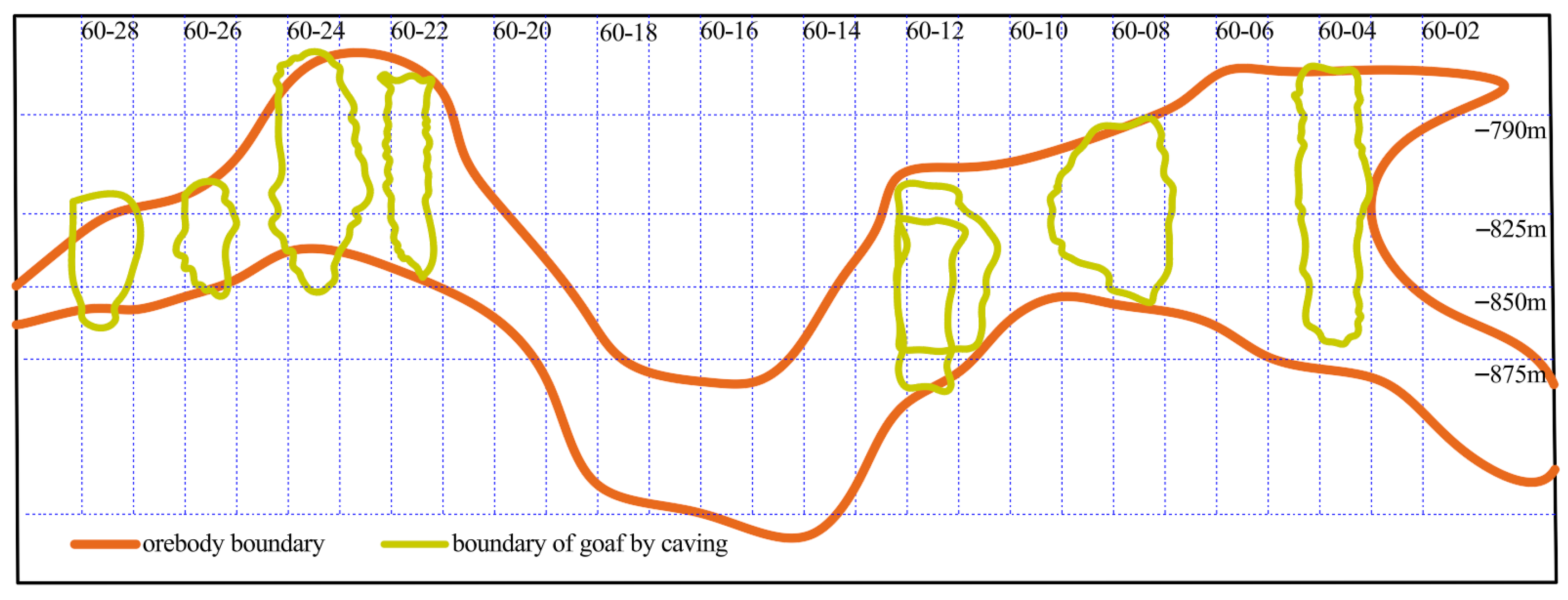
As shown in Figure 5, some high stopes have collapsed severely (60-8# and 60-12#), while others have not experienced obvious collapse (60-4# and 60-22#). Some goafs with relatively small heights also exhibit collapse phenomena (60-26# and 60-28#). The collapse locations are mainly in the central area of the stopes. High stopes collapse more severely than medium and low stopes. The goaf detection and inversion results indicate that the collapse morphology of the goafs north of Line 60 at Dongguashan is mainly characterized by a triangular collapse pattern on one sidewall, being large in the middle and small at both ends, showing that one sidewall collapses severely while the opposite sidewall remains relatively intact.
In summary, the high stopes north of Line 60 face issues such as severe goaf collapse, insufficient pillar stability, and difficulties in secondary extraction. These phenomena indicate that relying solely on experience or traditional support methods can no longer guarantee safe extraction. Therefore, it is necessary to conduct theoretical analysis and mechanical modeling research to optimize pillar design and combined mining schemes, thereby improving stope stability and ore recovery rate. This involves calculating the critical stress of pillars and section optimization schemes through mechanical models to enhance the buckling resistance of pillars, and analyzing the roof stress distribution under different combined mining methods to determine the bearing capacity of barrier pillars and backfill.

3. Methodology

3.1. Methodology Overview

The methodology of this study consists of four steps. First, field goaf detection data and engineering geological information were collected to identify the collapse characteristics of high stopes north of Line 60. The collapse thickness, collapse position, and sidewall failure morphology were used to define the instability problem. Second, considering the large height-to-width ratio of the secondary pillars, the pillar was simplified as a fixed-end compression member, and a buckling instability model was established to derive the critical load and critical stress. Third, the reserved pillar width was optimized by comparing the calculated critical stress, actual pillar stress, and safety factor. A safety factor greater than 1.6 was adopted as the stability criterion. Fourth, Protodyakonov’s arch theory was used to compare three combined mining schemes. The arch orientation, goaf span, arch-base stress, and load-bearing objects were analyzed to determine the preferred scheme. Finally, the theoretical results were compared with field goaf detection results to evaluate the applicability of the proposed method.

3.2. Pillar Mechanical Model

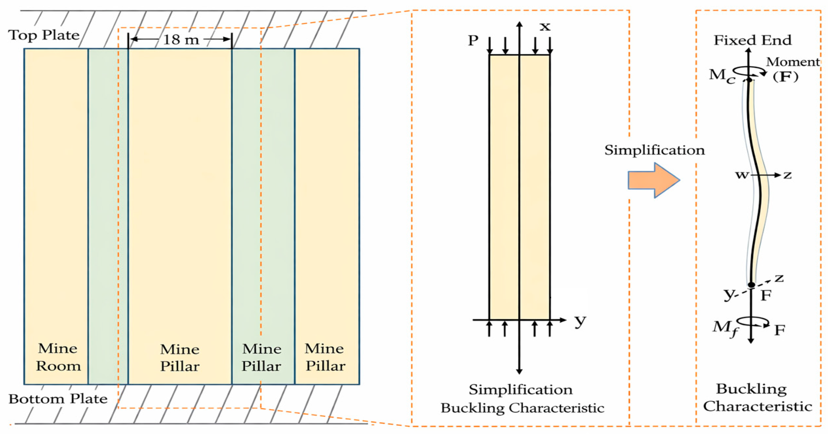
In some areas of the high stopes north of Line 60 at the Dongguashan Copper Mine, the stope height exceeds 100 m. During primary extraction, severe collapse occurred in some stopes, in which the influence of height on pillar stability cannot be ignored. According to the original design, both primary and secondary stopes are 18 m wide. When the stope height reaches 100 m, the height-to-width ratio of the secondary pillar exceeds 5. For pillars with a large height-to-width ratio, when subjected to axial loads, they are more prone to bending instability and buckling failure, as shown in Figure 6.
Considering the geometric characteristics and boundary conditions of the secondary pillar, the pillar is simplified as a fixed-end compression member in this study. This assumption is mainly based on the following considerations. First, the secondary pillar is in close contact with the roof and floor, and the surrounding ore body and backfill can provide certain end constraints during the mining process. Second, the height-to-width ratio of the secondary pillar exceeds 5 when the stope height reaches 100 m, indicating that bending instability may become one of the dominant failure modes under axial loading. Third, the purpose of this model is to obtain an analytical relationship between pillar geometry and critical instability stress for preliminary design optimization. Therefore, local discontinuity-controlled failure, blasting disturbance, and material heterogeneity are not explicitly included in this simplified model. Under these assumptions, the pillar is treated as a fixed-end rod, and the approximate differential equation for the deflection of the pillar can be written as:
d 2 w d 2 x = M x E I z = F w E I z + M e E I z
where w   is the deflection of the pillar, E   is the elastic modulus of the pillar, and I z is the moment of inertia of the pillar about the z -axis.
For ease of calculation, let k 2 = F / E I z . Equation (1) can be written as:
d 2 w d 2 x + k 2 w = M e E I z
Solving the differential Equation (2) yields:
w = A sin k x + B cos k x + M e F
Differentiating Equation (3) gives:
d w d x = A k cos k x B k sin k x
The boundary conditions for fixed ends can be written as:
when   x   =   0 ,   w   =   0 ,   d w d x = 0
when   x = h ,   w = 0 ,   d w d x = 0
Substituting the above boundary conditions into Equations (3) and (4), we can obtain:
B + M e F = 0 A k = 0 A sin k h + B cos k h + M e F = 0 A k cos k h B k sin k h = 0
Solving Equation (5), we can obtain:
cos k h 1 = 0 sin k h = 0
The roots satisfying the above equation, besides k h = 0 , have the smallest root of kh = 2π. Therefore, the critical pressure for pillar instability failure can be obtained as:
F = 4 π 2 E I z h 2
It can be seen from Equation (7) that the critical pressure of the pillar is mainly positively correlated with its own elastic modulus and section moment of inertia, and negatively correlated with the square of the pillar height. When the elastic modulus and height cannot be changed, altering the section properties to increase the moment of inertia of the section is the primary way to improve pillar stability. Then, dividing the critical pressure by the area yields the critical stress as:
σ = 4 π 2 E I z h 2 A 0
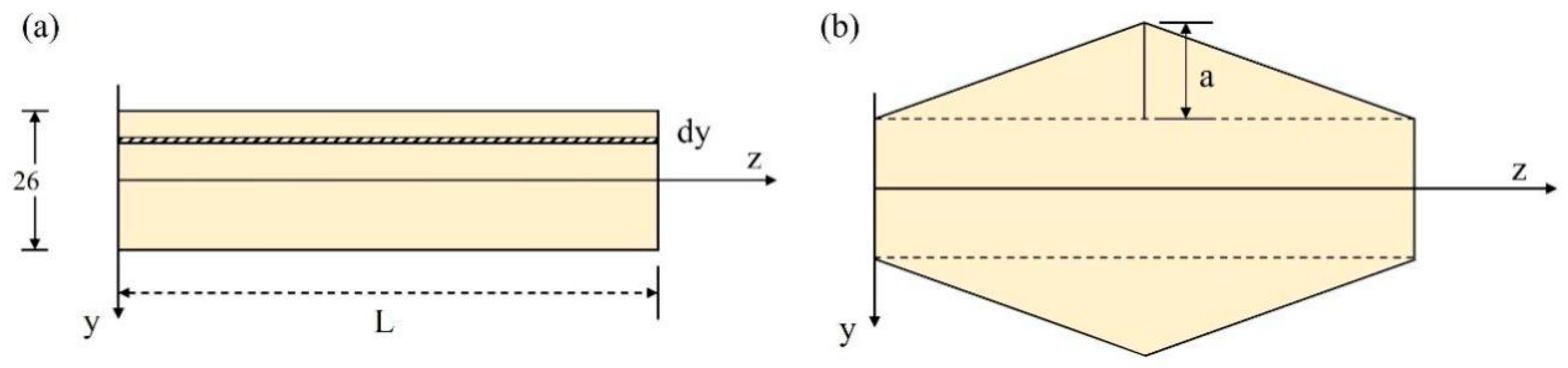
where A 0 is the cross-sectional area of the pillar. In Figure 7, the area of the rectangular section is 2 b l , and the area of the hexagonal section is 2 b l + a l .
The moment of inertia (second moment of area) of the section about the z-axis can be obtained from Equation (9):
I z = A y 2 d A
From Figure 7a, it can be seen that for the rectangular section, dA = l dy. Substituting into Equation (9), the moment of inertia for the rectangular section is:
I z 1 = b b l y 2 d y
Through integration, we obtain:
I z 1 = 2 l b 3 3
From Figure 7b, it can be seen that within the hexagonal section (combination of rectangle and triangle), dA satisfies the following equation:
d A = l a + b y a   d y , b < y a + b l   d y , b y b l a + b y a   d y , a b y < b
Substituting Equation (12) into Equation (9) and integrating yields the moment of inertia for the hexagonal section:
I z 2 = 2 l a a + b 4 12 a b 3 3 b 4 12 + 2 l b 3 3
In summary, by establishing the pillar mechanical model, we clarified the law that pillars with a high aspect ratio are prone to bending instability under axial loads, and derived the relationship between critical pressure and the section moment of inertia, elastic modulus, and pillar height. However, theoretical analysis alone is still insufficient to fully guide the actual extraction work of high stopes. To apply the theoretical results to engineering practice, further integration with pillar size optimization and mechanical analysis of combined mining schemes is required to quantitatively evaluate roof stress distribution and pillar stability under different extraction strategies. Therefore, in the next chapter, based on the theoretical calculation results, reasonable pillar section design and a mechanical model for combined mining will be explored, thus providing feasible solutions for the safe and efficient recovery of high stopes.

4. Results and Discussion

4.1. Pillar Size Optimization

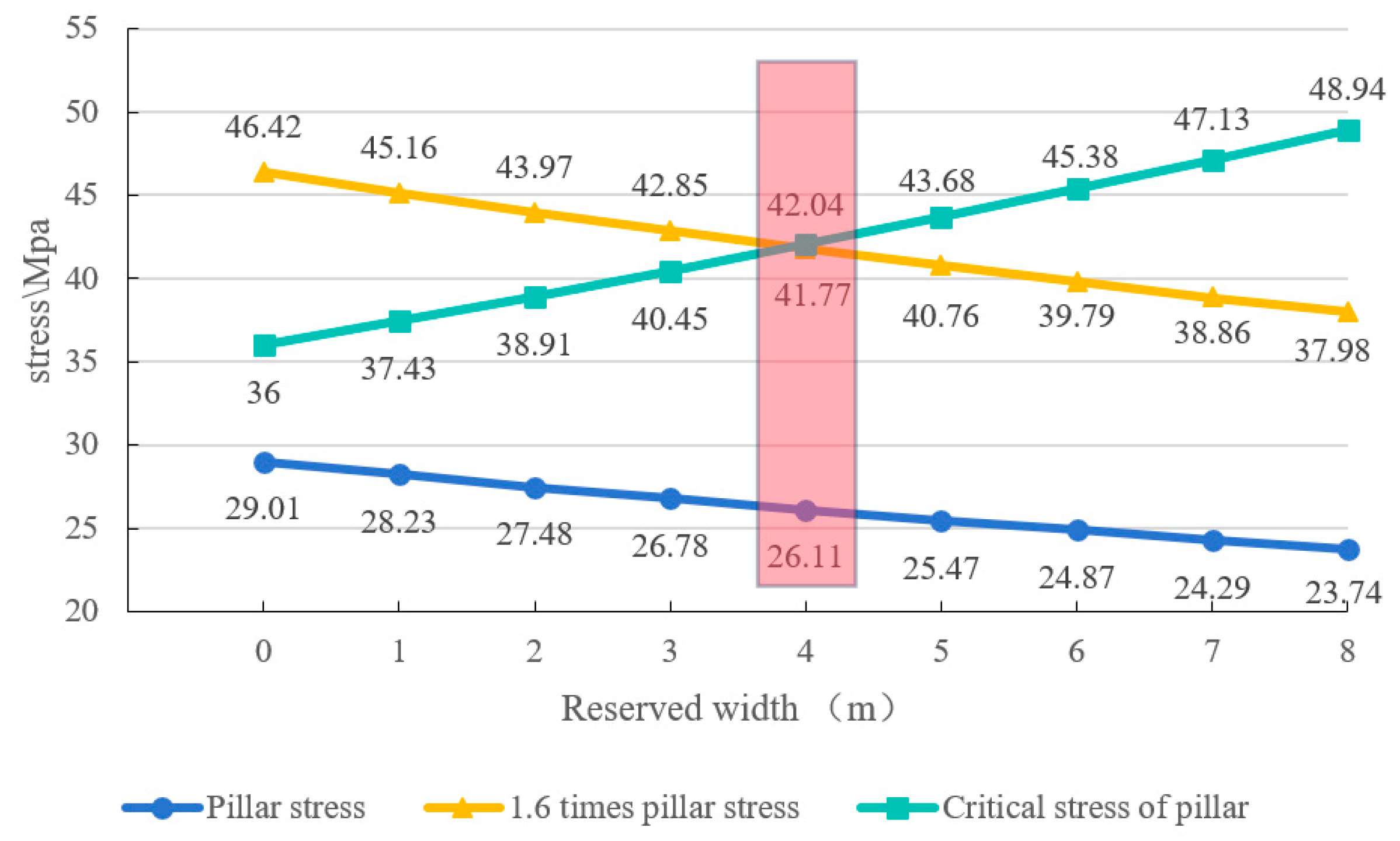
According to the theoretical calculation results, the relationship between the reserved pillar width and pillar stability is summarized in Table 1 and Figure 8. The actual pillar stress decreases gradually as the reserved width increases, from 29.01 MPa at 0 m to 23.74 MPa at 8 m. In contrast, the critical stress of the pillar increases from 36.00 MPa to 48.94 MPa with the increase in reserved width. This indicates that increasing the reserved width can improve the buckling resistance of the pillar by increasing the section moment of inertia and reducing the actual stress level.
In this study, the safety factor is defined as the ratio of the critical stress to the actual pillar stress, and a safety factor greater than 1.6 is adopted as the stability criterion. Therefore, the pillar can be considered stable only when the critical stress is greater than 1.6 times the actual pillar stress. As shown in Table 1 and Figure 8, when the reserved width is less than 4 m, the safety factor is lower than 1.6, indicating that the pillar does not meet the stability requirement. When the reserved width reaches 4 m, the critical stress is 42.04 MPa, the actual pillar stress is 26.11 MPa, and the safety factor increases to 1.61, which satisfies the stability criterion. Although further increasing the reserved width can continue to improve the safety factor, it would reduce ore recovery. Therefore, considering both pillar stability and resource recovery, 4 m is recommended as the lower limit of the reasonable reserved pillar width.

4.2. Stress Analysis for Combined Mining Optimization

4.2.1. Mechanical Model for Combined Mining

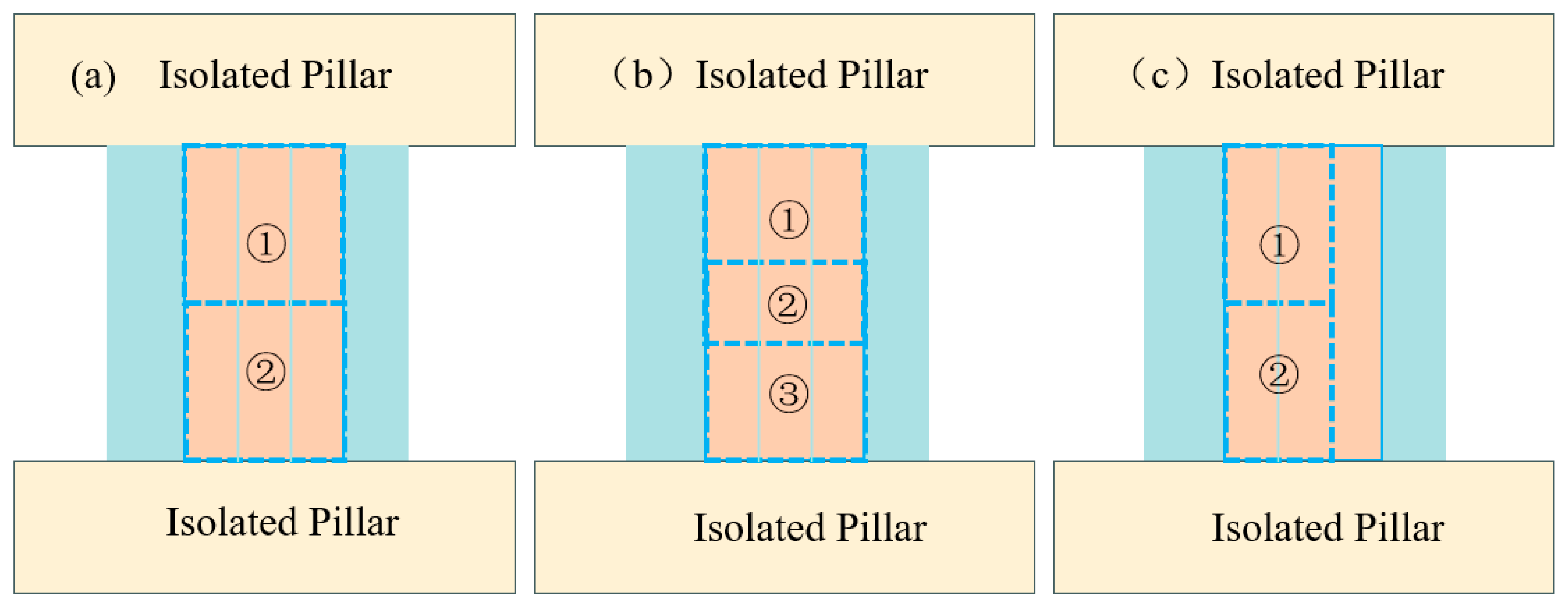
Due to factors such as stope height and geological characteristics, after the extraction of primary stopes, some adjacent stopes have experienced collapse, severely affecting the progress of secondary extraction. To address the above issues, combined mining schemes are proposed, mainly including the combined mining of three stopes and the combined mining of two stopes, where the combined mining of three stopes is further divided into two-step extraction and three-step extraction.
This section primarily investigates the theoretical feasibility of these schemes. The specific schemes are shown in Figure 9: (a) is the two-step extraction scheme for three stopes, (b) is the three-step extraction scheme for three stopes, and (c) is the two-step extraction scheme for two stopes.
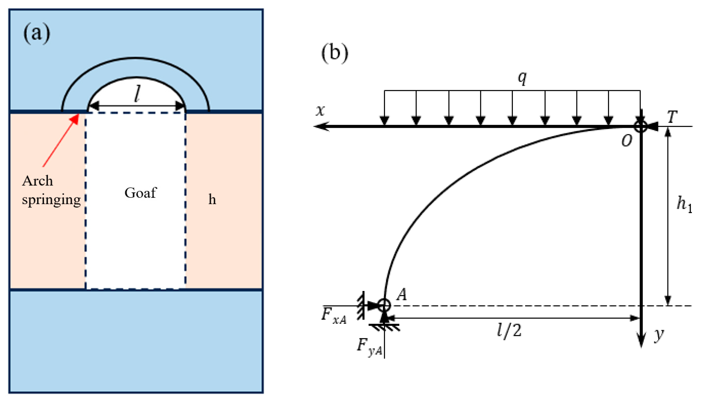
After mining, a goaf is formed within a certain area. Under unsupported conditions, the roof strata of the goaf become suspended. Under the action of vertical self-weight stress and horizontal tectonic stress, the roof strata transition from a compressive state to a tensile state. Given that the tensile strength of rock masses is far lower than their compressive strength, the roof rock will fail under tension, causing some rock mass to collapse, after which the roof stress field redistributes. Engineering practice results show that as failure intensifies, the surrounding rock of the roof forms an arched collapse zone, and a load-bearing rock arch (also known as a Protodyakonov’s arch) forms above the collapse zone, as shown in Figure 10.
In Figure 10a, FxA is the horizontal reaction force at the arch base, FyA is the vertical reaction force at the arch base, T is the horizontal reaction force at the arch crown, q is the vertical load, h is the goaf height, h1 is the height of the collapse zone, and l is the goaf span.
Figure 10b shows a simplified mechanical diagram of the collapse arch after the goaf roof collapses. After roof collapse, fractures develop in the rock layers, preventing rotational constraints, so the base and crown can be considered hinged. According to structural mechanics, the arch axis equation y = f(x) satisfies Equation (14).
f ( x ) = 4 h 1 x 2 l
According to Protodyakonov’s arch theory, under unsupported conditions, the height h1 of the collapse zone satisfies Equation (15):
h 1 = γ r H + c r cot φ r 1 sin φ r c r cot φ r 1 sin φ r 2 sin φ r h 2 2 + l 2 2 h 2
where γ is the unit weight of the roof rock mass, g is the acceleration due to gravity (9.8 m/s2), H is the depth of the stope from the surface, c r is the cohesion of the roof rock mass, and ϕ r is the internal friction angle of the roof rock mass.
Then, based on static equilibrium conditions, the support reactions can be obtained as:
F x A = T = q l 2 8 h 1
F y A = q l 2
Therefore, the axial force F A at the arch base is:
F A = q l 2 16 h 1 2 + l 2 16 h 1 2
According to Protodyakonov’s theory, the thickness d of the equilibrium arch is approximately twice the collapse height, i.e., 2 h 1 . Therefore, the stress at the base of the equilibrium arch can be obtained as:
σ A = q l 4 h 1 16 h 1 2 + l 2 16 h 1 2
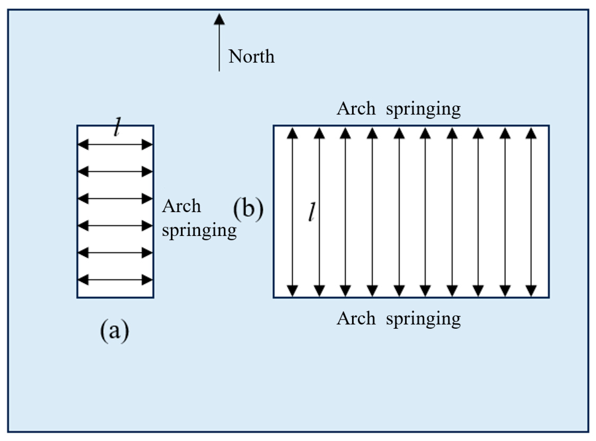
During underground excavation, stress redistribution in the rock mass always occurs along the direction of the shorter span. Therefore, the Protodyakonov’s arch will also form along the short side of the goaf, as shown in Figure 11. If a tunnel (a) is extended from the south, when the tunnel length exceeds the tunnel span, the Protodyakonov’s arch will be oriented east–west. If, at this point, the tunnel stops extending north and instead turns east, when the length of the goaf in the east–west direction exceeds its length in the north–south direction, the Protodyakonov’s arch will then be oriented along the direction of the shorter span, i.e., north–south.

4.2.2. Analysis of Stress State in Goaf Surrounding Rock

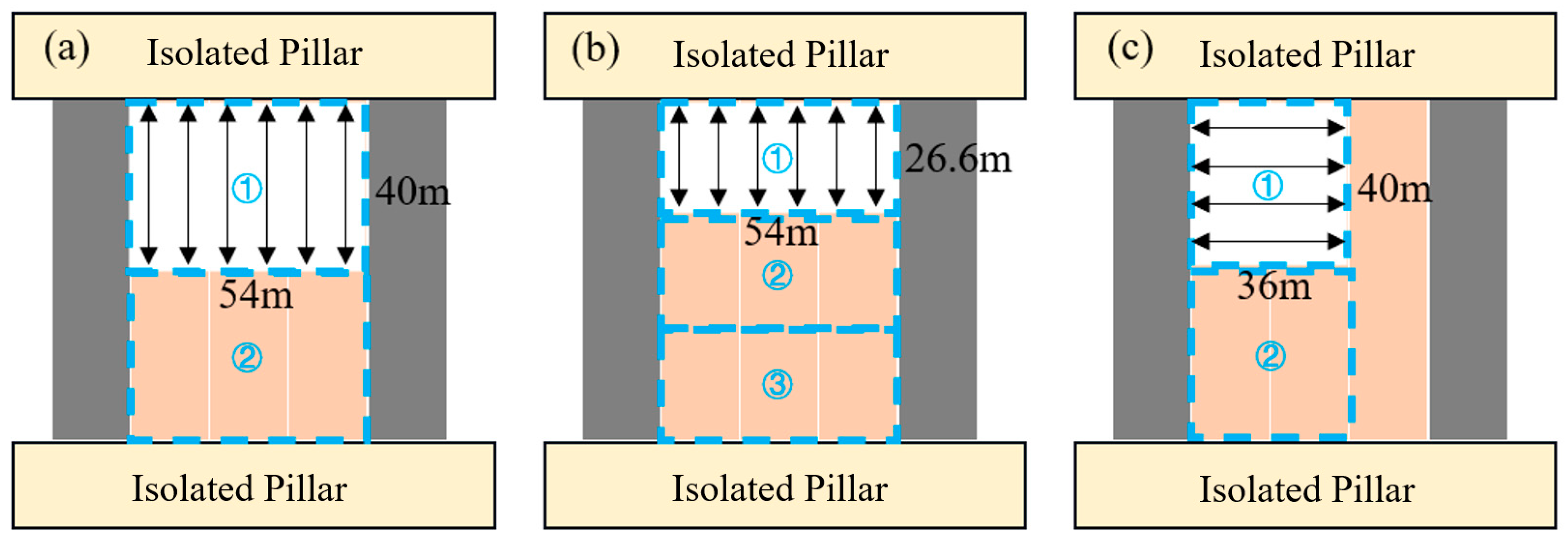
According to the design of the combined mining schemes, for the two-step combined mining of three stopes (Figure 12a), after the first step of extraction, a goaf of 54 m × 40 m is formed. For the three-step combined mining of three stopes (Figure 12b), after the first step of extraction, a goaf of 54 m × 26.6 m is formed. For the two-step combined mining of two stopes (Figure 12c), after the first step of extraction, a goaf of 36 m × 40 m is formed, as shown in Figure 12. At this point, Figure 12a–c will form a Protodyakonov’s arch with the goaf spans in the directions of 40 m, 26.6 m, and 36 m, respectively. It can be seen from the figure that for Figure 12a,b, the Protodyakonov’s arch will form along the strike direction of the ore body. The arch base load acts on the barrier pillars and the ore body to be extracted in the second step. For Figure 12c, the Protodyakonov’s arch will form perpendicular to the strike direction of the ore body. Within the panel, the arch base load acts on the left backfill and the remaining ore body on the right. Therefore, after extracting Figure 12a,b, the impact on the backfill on both sides is relatively small, and the bearing capacity and stability of the barrier pillar should be primarily analyzed and considered. Conversely, after extracting Figure 12c, the impact on the barrier pillar is relatively small, and the stability of the right ore body and backfill should be primarily analyzed and considered.
Substituting l a = 40   m , l b = 26.6   m , and l c = 36   m into Equation (19), the stresses at the arch base for the three schemes are obtained as σ a = 37.6   MPa , σ b = 31.3   MPa , and σ c = 34.5   MPa , respectively. It can be seen that in the combined mining of three stopes, the pressure borne by the barrier pillar in the three-step extraction scheme is about 83% of that in the two-step extraction scheme. In the combined mining of two stopes, the stress at the arch base is greater than that in the three-step extraction scheme for three stopes but less than that in the two-step extraction scheme for three stopes, representing a moderate stress state. Moreover, in the combined mining of two stopes, the roof pressure is primarily borne by the left backfill and the right ore body, with the barrier pillar playing a secondary load-bearing role, resulting in better stability for the barrier pillar. In this case, attention should be paid to the stability of the backfill and ore body on both sides. In practical application, considering both efficiency and safety, the two-step extraction scheme for two stopes can be selected.

5. Conclusions

Frequent collapses occur in high stopes north of Line 60 at the Dongguashan Copper Mine, especially in goafs 60-8#, 60-12#, and 60-24#, where collapse is severe. In stope 60-8#, the maximum collapse thickness exceeds 16 m. Severe collapse in primary stopes not only significantly increases the difficulty of secondary extraction, leading to higher stope loss rates, but also, during blasting operations, protruding backfill can easily collapse into secondary stopes, causing increased stope dilution. This study, through field investigation, theoretical calculation, and model-based optimization validation of pillar dimensions, cross-sectional shapes, and combined mining schemes, forms a complete chain from problem identification to design solutions, leading to the following conclusions:
(1)
The main causes of collapse in high stopes north of Line 60 at the Dongguashan Copper Mine are the influence of geological structures, fractured ore rock, and poor stability. The collapse morphology is primarily characterized by a triangular collapse feature on one sidewall, being large in the middle and small at both ends, indicating severe collapse on one sidewall while the opposite sidewall remains relatively intact.
(2)
Based on the characteristic of high-aspect-ratio pillars being prone to bending instability, the pillar was simplified as a rod with fixed ends. A mechanical model for the triangular pillar was established, and the critical instability condition was derived. This clarified the quantitative relationship between the pillar’s critical stress and its elastic modulus, section moment of inertia, and height, identifying an effective way to enhance stability by optimizing the cross-sectional shape.
(3)
Theoretical calculations show that by adjusting the shape of the primary stope (reserving a triangular pillar) and setting the secondary extraction pillar stope as a hexagonal pillar, the buckling resistance and overall stability of the pillar can be significantly improved. As the reserved pillar width increases, its critical pressure increases exponentially. When the reserved width exceeds 4 m, the pillar safety factor is greater than 1.6, indicating a high level of stability. Therefore, 4 m is recommended as the lower limit for a reasonable reserved width.
(4)
Protodyakonov’s arch theory was introduced to establish a mechanical model for combined mining. A comparative analysis of combined mining schemes for three stopes and two stopes was conducted. Calculation results indicate that the two-stope combined mining scheme is recommended. In this mode, the barrier pillar experiences less pressure, offers better stability, and facilitates its safe subsequent recovery. Furthermore, cumulative damage to the surrounding rock consists of direct blasting damage (determining the damage range) and vibration damage (determining the final damage degree); the latter has a crucial impact on the long-term stability of the engineering structure.
(5)
The proposed optimization procedure has practical applicability and can be replicated in similar deep metal mines with high stopes, high-aspect-ratio pillars, severe goaf collapse, and difficult secondary extraction. When applied to different geological settings or mining configurations, the workflow of field goaf detection, collapse morphology identification, pillar instability modeling, reserved pillar width optimization, and combined mining scheme comparison can remain unchanged. However, the key parameters, such as stope height, pillar geometry, rock mass mechanical properties, in situ stress conditions, goaf span, and backfill conditions, should be adjusted according to the specific engineering case.
In addition, the analytical model simplifies the pillar as a homogeneous fixed-end compression member and does not fully consider discontinuities, blasting disturbance, time-dependent damage, or local nonlinear failure of the rock mass. Future studies should combine this optimization method with numerical simulation, microseismic monitoring, displacement monitoring, and long-term field verification to further improve the reliability of high-stope stability control.

Author Contributions

Field investigation and data collection: M.H. and Q.Z.; methodology and data curation: J.G. and J.W. (Jiachuang Wang); writing, revision and editing: J.W. (Jing Wu). All authors have read and agreed to the published version of the manuscript.

Funding

This research received no external funding.

Institutional Review Board Statement

Not applicable.

Informed Consent Statement

Not applicable.

Data Availability Statement

Dataset available on request from the authors. The raw data supporting the conclusions of this article will be made available by the authors on request.

Conflicts of Interest

Author Mingjian Huang was employed by the Guangdong Hongda Holdings Group Co., Ltd. The remaining authors declare that the research was conducted in the absence of any commercial or financial relationships that could be construed as a potential conflict of interest.

References

  1. Salmi, E.F.; Azhari, F. Assessing risk of pillar instabilities in abandoned mine workings through probabilistic modelling: A case study in the West Midlands, UK. Eng. Geol. 2026, 365, 108649. [Google Scholar] [CrossRef]
  2. Shu, S.; Wang, W.; Liu, C.; Yuan, C.; Ma, Y.; Tian, X.; Du, R.; Ge, S. Study on the mining stress field distribution law beneath isolated coal pillar in close coal seam and reasonable location of the roadway. Sci. Rep. 2026, 16, 12281. [Google Scholar] [CrossRef]
  3. Gao, X.; Wang, Y.; Li, Y.M. Research on stability analysis and control technology of roadways in the underlying isolated island working face. Sci. Rep. 2026, 16, 9903. [Google Scholar] [CrossRef]
  4. Sun, Z.; Zhao, C.; Luo, Q.; Huang, R.; Jia, N.; Xing, J.; Niu, J.; Wei, C. Modified linear superposition method for stress tensor field analysis and its application to compressed air energy storage chamber group. Undergr. Space 2026, 27, 112–131. [Google Scholar] [CrossRef]
  5. Yoon, H.D.; Song, J.J. Numerical study on pillar stress distribution in room-and-pillar hard rock mines using stress concentration factor based on tributary area: Bridging to pressure arch effect. Int. J. Rock Mech. Min. Sci. 2026, 199, 106198. [Google Scholar] [CrossRef]
  6. Liu, H.; Zhao, Z.; Ma, Q.; Liu, X.; Zhu, L. Degradation mechanism of microstructure of residual coal pillars during highly mineralized mine-water storage in coal mine goaf. Undergr. Space 2026, 26, 479–497. [Google Scholar] [CrossRef]
  7. Li, Q.; Yang, S.; Song, Y.; Wei, W.; Zhang, J. Study on deformation mechanism and control technology of rock pillar in near-vertical coal seams mining. Bull. Eng. Geol. Environ. 2026, 85, 89. [Google Scholar] [CrossRef]
  8. Kumar, M.; Avchar, A.; Sinha, S.; Swamy, S.V. Integrated approaches for pillar design and stability assessment in underground hard rock mining: From empirical models+ to machine learning. Phys. Chem. Earth 2026, 142, 104235. [Google Scholar] [CrossRef]
  9. Wang, J.-C.; Dong, L.-J. Risk assessment of rockburst using SMOTE oversampling and integration algorithms under GBDT framework. J. Cent. South Univ. 2024, 31, 2891–2915. [Google Scholar] [CrossRef]
  10. Wang, J.; Ma, H.; Yan, X. Rockburst intensity classification prediction based on multi-model ensemble learning algorithms. Mathematics 2023, 11, 838. [Google Scholar] [CrossRef]
  11. Dong, L.; Huang, X.; Li, S.; Wang, J. Research on microseismic parameter prediction for rock mass instability disasters based on time series models. J. Appl. Geophys. 2026, 250, 106278. [Google Scholar] [CrossRef]
  12. Wang, J.; Dong, L.; Ji, S. Rock mass instability early warning model: A case study of a high and steep annular slope mining areas using Sen’s slope trend analysis. Tunn. Undergr. Space Technol. 2025, 159, 106514. [Google Scholar] [CrossRef]
  13. Wang, J.; Dong, L. Research and application of mine microseismic signal processing based on joint PKO-VMD with wavelet threshold functions. Measurement 2025, 256, 118159. [Google Scholar] [CrossRef]
  14. Zhang, Y.; Xue, B.; Liu, X.; Wei, J.; Li, Y.; Zhang, L.; Zhang, H.; Jia, Z. Research on the impact of water inrush on the stability of coal pillar in a mining face based on the three-field coupling method. Energy Explor. Exploit. 2025, 43, 1558–1587. [Google Scholar] [CrossRef]
  15. Mehra, A.; Budi, G. 3D Modelling approach to identify parametric configurations for pillar stability in underground metal mine: A case study. Geomat. Nat. Hazards Risk 2024, 15, 2367630. [Google Scholar] [CrossRef]
  16. Ma, H.; Wei, X.; Shi, X.; Liang, X.; Bai, W.; Ge, L. Evaluation Methods of Salt Pillar Stability of Salt Cavern Energy Storage. Energies 2022, 15, 7570. [Google Scholar] [CrossRef]
  17. Patanwar, Y.K.; Deb, D. Development of Coupled FEM and Fuzzy Rules–Based Procedures for Mitigation of Uncertainty in Forecasting Stability of Underground Pillars. Int. J. Geomech. 2022, 22, 04021276. [Google Scholar] [CrossRef]
  18. Sarkar, F.; Mishra, K. Determination of Most Favorable Room and Post Pillar Combination in Cut and Fill Stopes: A Finite Element Method (FEM) Based Analysis. J. Inst. Eng. Ser. D 2024, 106, 691–703. [Google Scholar] [CrossRef]
  19. Li, C.; Zhou, J.; Armaghani, D.J.; Li, X. Stability analysis of underground mine hard rock pillars via combination of finite difference methods, neural networks, and Monte Carlo simulation techniques. Undergr. Space 2020, 6, 379–395. [Google Scholar] [CrossRef]
  20. Vanga, M.; Ojha, M. Modeling the seismic wave equation using a staggered grid finite-difference method optimized with a genetic algorithm. J. Seism. Explor. 2025, 34, 1–13. [Google Scholar] [CrossRef]
  21. Vinay, L.S.; Bhattacharjee, R.M.; Ghosh, N.; Kumar, S. Machine learning approach for the prediction of mining-induced stress in underground mines to mitigate ground control disasters and accidents. Geomech. Geophys. Geo-Energy Geo-Resour. 2023, 9, 159. [Google Scholar] [CrossRef]
  22. Kadkhodaei, M.H.; Ghasemi, E.; Zhou, J.; Zahraei, M. Evaluation of underground hard rock mine pillar stability using gene expression programming and decision tree-support vector machine models. Deep Undergr. Sci. Eng. 2024, 4, 18–34. [Google Scholar] [CrossRef]
  23. Li, C.; Zhou, J.; Du, K.; Dias, D. Stability prediction of hard rock pillar using support vector machine optimized by three metaheuristic algorithms. Int. J. Min. Sci. Technol. 2023, 33, 1019–1036. [Google Scholar] [CrossRef]
  24. Majeed, Y.; Sani, K.M.; Emad, M.Z. Estimating Pillar Strength for Rock Salt Mines of the Salt Range Pakistan Using Statistical and Artificial Neural Network Modeling Techniques. Min. Metall. Explor. 2024, 41, 2161–2175. [Google Scholar] [CrossRef]
  25. Xie, X.; Zhang, H. Research on Hard Rock Pillar Stability Prediction Based on SABO-LSSVM Model. Appl. Sci. 2024, 14, 7733. [Google Scholar] [CrossRef]
  26. Zou, G.; Zhou, J.; Song, T.; Yang, J.; Li, K. Hierarchical Intelligent Control Method for Mineral Particle Size Based on Machine Learning. Minerals 2023, 13, 1143. [Google Scholar] [CrossRef]
  27. Shan, P.; Sun, H.; Lai, X.; Dai, J.; Gao, J.; Yang, P.; Li, W.; Li, C.; Yan, C. Numerical Method for Predicting and Evaluating the Stability of Section Coal Pillars in Underground Longwall Mining. Front. Earth Sci. 2022, 10, 894118. [Google Scholar] [CrossRef]
  28. Cai, X.; Chen, L.; Zhou, Z.; Cheng, R.; Yuan, J. A Feature Fusion-Based Framework for Robust Prediction of Underground Pillar Stability Under Small-Sample Conditions. Rock Mech. Rock Eng. 2025, 58, 13565–13586. [Google Scholar] [CrossRef]
  29. Zvarivadza, T.; Grobler, H.; Olubambi, P.A.; Onifade, M.; Khandelwal, M. Hybrid pillar stress analysis: Integrating numerical modelling, machine learning, and geostatistics for improved stability in hardrock mining. Results Earth Sci. 2025, 3, 100129. [Google Scholar] [CrossRef]
  30. Wang, C.; Huang, Y.; Zhang, Z.; Su, L.; Lu, H.; Hao, Y. Research on the stability of stope roof and barrier pillars in short-wall interval filling mining. Sci. Rep. 2025, 15, 40811. [Google Scholar] [CrossRef] [PubMed]
  31. Cortez, J.; Browning, J.; Marquardt, C. Impact of soft or stiff igneous intrusions and contact properties on the stability of room-and-pillar mines. Bull. Eng. Geol. Environ. 2025, 85, 61. [Google Scholar] [CrossRef]
  32. Maina, D.; Konietzky, H. Factor of safety analysis for mine pillar considering the influence of the intermediate principal stress component. Green Smart Min. Eng. 2024, 1, 241–248. [Google Scholar] [CrossRef]
  33. Hao, H.; Li, J.; Li, G.; Sun, Y.; Yang, S.; Shao, Z.; Tian, B.; Wo, X. Stability analysis and engineering implications of lateral mining-induced narrow coal pillars under double-roadway layout in deep mines. Results Eng. 2026, 29, 109152. [Google Scholar] [CrossRef]
  34. Zhang, Q.; Huang, M.; Guo, J. A Simulation Analysis of the Stability of Tall and Collapse-Prone Stopes: A Case Study of the Dongguashan Copper Mine. Appl. Sci. 2024, 14, 10608. [Google Scholar] [CrossRef]
Figure 1. Large-diameter longhole sublevel open stoping with subsequent backfill mining method.
Applsci 16 04738 g001
Figure 2. Plan and section views of stope 60-8# failure.
Applsci 16 04738 g002
Figure 3. Plan and section views of stope 60-12# failure.
Applsci 16 04738 g003
Figure 4. Plan and section views of stope 60-24# failure.
Applsci 16 04738 g004
Figure 5. Section view of goaf detection results for stopes along Line 61.
Applsci 16 04738 g005
Figure 6. Mechanical model of the pillar.
Applsci 16 04738 g006
Figure 7. Cross-sectional shapes. (a) Rectangular pillar cross-section, (b) Hexagonal pillar cross-section.
Applsci 16 04738 g007
Figure 8. Relationship between pillar reserved width and critical stress.
Applsci 16 04738 g008
Figure 9. Combined mining schemes. The colorful area represents the orebody, each number represents a stope.
Applsci 16 04738 g009
Figure 10. Protodyakonov’s arch model. (a) Schematic of the Protodyakonov arch above the goaf, (b) Simplified mechanical model of the caving arch.
Applsci 16 04738 g010
Figure 11. Position of Protodyakonov’s arch bases. (a) Schematic of Protodyakonov arch distribution during north-south excavation, (b) Schematic of Protodyakonov arch distribution during east-west excavation.
Applsci 16 04738 g011
Figure 12. Distribution state of Protodyakonov’s arch. The white area represents the goaf, and other area represents the orebody, each number represents a stope.
Applsci 16 04738 g012
Table 1. Optimization results of reserved pillar width based on pillar stability criteria.
Reserved Width/mCritical Stress/MPaActual Pillar Stress/MPa1.6 × Actual Stress/MPaSafety FactorStability Judgment
036.0029.0146.421.24Unstable
137.4328.2345.161.33Unstable
238.9127.4843.971.42Unstable
340.4526.7842.851.51Unstable
442.0426.1141.771.61Stable
543.6825.4740.761.71Stable
645.3824.8739.791.82Stable
747.1324.2938.861.94Stable
848.9423.7437.982.06Stable
Disclaimer/Publisher’s Note: The statements, opinions and data contained in all publications are solely those of the individual author(s) and contributor(s) and not of MDPI and/or the editor(s). MDPI and/or the editor(s) disclaim responsibility for any injury to people or property resulting from any ideas, methods, instructions or products referred to in the content.