Article

Evaluation of Mechanical Stability, and Magnetic and Acoustic Properties of a Transformer Core Made of Amorphous Steel Consolidated with a Silane-Based Hybrid Binder

by
Jolanta Nieroda
1,
Grzegorz Kmita
2,†,
Michal Kozupa
2,†,
Szymon Piela
2,†,
Maciej Sitarz
3 and
Andrzej Rybak
1,*
1
ABB Corporate Technology Center, Starowislna 13A, 31-038 Krakow, Poland
2
Hitachi Energy Research, Pawia 7, 31-154 Krakow, Poland
3
Department of Silicate Chemistry and Macromolecular Compounds, Faculty of Materials Science and Ceramics, AGH University of Science and Technology, Mickiewicza 30, 30-059, Krakow, Poland
*
Author to whom correspondence should be addressed.
ABB Corporate Research Center, Starowislna 13A, 31-038 Krakow, Poland; at the Time of This Research.
Appl. Sci. 2025, 15(9), 5141; https://doi.org/10.3390/app15095141
Submission received: 31 March 2025 / Revised: 28 April 2025 / Accepted: 2 May 2025 / Published: 6 May 2025
(This article belongs to the Special Issue Advances in Properties of Thin Film Materials)

Abstract

:

Featured Application

The presented silane-based hybrid binder allows the preparation of an amorphous magnetic core with improved magnetic and acoustic properties.

Abstract

The ongoing electrification process also requires improvements in the efficiency of power transmission devices, such as transformers, the main part of which is the magnetic core. Despite great progress in the development of core material, losses and audible noise during their operation is still a critical issue to be solved. Currently, a magnetic material used to produce the transformer core is amorphous steel, which is gaining popularity. Compared to traditionally used grain-oriented silicon electrical steel, a significantly larger number of very thin amorphous ribbons is needed to produce the core, which is due to the fact that they are about an order of magnitude thinner, making mechanical stability a challenge. The presented article describes the preparation of a hybrid binder for amorphous steel based on the two types of silanes, tetraethyl orthosilicate and 1,2-bis(triethoxysilyl)ethane, for which their anticorrosive character and good dielectric properties were confirmed. Using the obtained binders, model toroidal cores were produced and their magnetic and acoustic properties were tested. The obtained results indicate that the applied silane-based hybrid binders improved important functional properties by reducing the magnetic no-load losses and audible noise.

1. Introduction

The number of electrical devices used in industry and households is increasing year by year, which causes a continuous increase in the demand for electrical energy [1]. Although the way electricity is produced is undergoing continuous transformation, a large part of it is still produced using fossil fuels, so an increase in energy demand may result in an increase in CO2 emission, which, in turn, requires the introduction of regulations. Reducing the carbon footprint can be achieved in various ways, such as by producing and using renewable energy, modernizing technology, or investing in CO2 capture and storage infrastructure [2]. Despite the above-mentioned propositions which usually require additional funding, it is possible to reduce energy consumption by the development and manufacturing of more-energy-efficient devices which will result in a cost and carbon footprint reduction. Not only are the end devices important, but each stage of energy production and transmission should be characterized by low energy losses; hence, the huge interest in increasing the energy efficiency of distribution transformers has been observed for years. The main part of the transformer is a ferromagnetic core [3,4]. The first material used for transformer cores was shaped iron, but, over time, isotropic hot-rolled steel, then anisotropic cold-rolled grain-oriented steel, and then high-permeability steel came into use. In later stages, domain-refined steel, microcrystalline steel, nanocrystalline steel, and, finally, amorphous steel were used [5,6]. Amorphous steel, called also metallic glass, is an amorphous metal characterized by the fact that its atoms do not have a long-range order. It is received from melted alloy through solidifying with very rapid cooling, 106 K/s [7,8]. The final shape of the material is a thin—for example, 25 µm—ribbon, which possess outstanding magnetic properties like a high magnetic permeability and easy magnetization [9,10]. Easier magnetization is the solution for problems observed during core development, mainly hysteresis losses. Using amorphous steel for core production also allows for a reduction in the eddy current losses, as this material exhibits high resistivity [11,12]. This kind of loss is strongly related to the thickness of the magnetic material [8]; therefore, using a very thin amorphous ribbon strengthens this positive effect. Taking into account the above benefits, the total amorphous core losses are 70% lower in relation to the core made of regular grain-oriented steel [13]. Despite such great progress, there are still some drawbacks when using an amorphous metal ribbon for the transformer core production. The disadvantage of the amorphous metal ribbon is that it is very thin, easily deformed, and, thus, prone to the magnetostriction effect. In the presence of the magnetic field, the magnetic material changes its dimensions and, as a result, starts to deform. A direct consequence of the frequent deformation of amorphous laminates is an audible sound, which is 3–5 dB higher for the core made of amorphous steel, in relation to the transformer core made of the grain-oriented steel [13]. During the fabrication of the amorphous steel, rapid cooling is mandatory, but this results in quenching stresses. Such stresses can be reduced by annealing at an elevated temperature [14,15], which is also used for the magnetization process. Unfortunately, annealing turns the amorphous material into a brittle form, which makes it more complicated for further processing. The application of the binder between laminates is a solution for both the aforementioned problems [16] as it leads to core solidification. Topics related to core solidification and, thus, strengthening it are known; however, they are presented mostly in patents, and research data in scientific papers are limited. The problem with the transportation of the annealed amorphous core can be solved by applying a ceramic coating [17] or resin [18] on the edge of the core. It is also possible to find patents where the resin was applied directly on the amorphous ribbon, aiming to receive a substrate covered with insulation material [19,20]. Finally, there are two patents which present solutions on how to reduce the audible noise of the working magnetic core. One of them describes the application of a dielectric, high-strength tape on the columns [21], while, in the second one, an organometallic binder was applied [16]. In both cases, the applied solutions results in a reduction in the audible noise of the amorphous magnetic core.
It is worth mentioning the authors’ previous scientific paper, in which the binder was applied directly on the amorphous metal ribbon, and then the magnetic core was formed [22]. In that work, we presented polyimide as a binder for the amorphous metal ribbon, and, in the first step, the quality of the applied layer was confirmed with Confocal Microscopy and Scanning Electron Microscopy. Moreover, stable dielectric values, an anticorrosive character, and good binding properties were confirmed. The last paragraphs of the paper [22] describe magnetic and acoustic properties, and the most important conclusion was that the applied solution resulted in a lowering of not only audible noise, but also magnetic losses.
It was highlighted in [22] that a proper binder should be characterized with a good wettability of the amorphous metal and should create a solid bond with the substrate. At the same time, it cannot cause—and it is even expected to prevent—the degradation of the metallic surface by the corrosion process. The applied layer needs to be dielectric and be of good quality, free of cracks. In order to avoid cracks, it is worth considering the value of the coefficient of thermal expansion (CTE), which should be similar to the substrate, as we highlighted in the authors’ other work [23]. A mismatched binder can cause additional stress and, as a result, increases the core losses and exciting current. It can then be observed as a more noticeable magnetostriction effect and amplified noise [21]. Considering the above requirements, we proposed a second type of the hybrid binder for the amorphous metal ribbon based on alkoxysilanes, namely, on tetraethoxysilane (TEOS) and 1,2-bis(triethoxysilyl)ethane (BTSE) [23]. The TEOS and BTSE layers were deposited in a stepwise way, TEOS directly on the metallic glass ribbon, with the BTSE layer on the top. Adequate TEOS properties are confirmed in the literature, like chemical and thermal stability [24], a good dielectric constant [25], and a low CTE [26]. Moreover, it has been proven that TEOS-based silica layers improve the corrosion resistance of various metallic substrates, like aluminum, steel, copper, and magnesium [27,28,29,30]. Despite good overall properties, layers based on TEOS are rather rigid; therefore, the second type of the silane was used, namely, BTSE, in order to create a layered hybrid structure. Dral et al. [26] explained that BTSE possesses higher rotational freedom and more empty volume in the final layer. Consequently, the BTSE layer is more flexible. The same as TEOS-based layers, BTSE films protect metallic surfaces from corrosion [31,32]. The suitability of sequential deposition, where the first deposited layer is TEOS and the second is BTSE, has been confirmed in our other paper [33]. The results of the spectroscopic and rheological measurements provide information that the TEOS sol reacts faster than BTSE. A faster hydrolysis of TEOS leads to a high number of reactive hydroxyl groups, ready to couple with a metallic surface and with hydrolyzed BTSE.
The objective of the work presented here is to complete our previous scientific work [23], in which it was confirmed that the TEOS-BTSE hybrid layer deposited on the amorphous metal ribbon is continuous and crack-free. Furthermore, it was observed that the CTE of the first TEOS-based layer is similar to that of the metallic glass substrate, suggesting that it should not induce additional mechanical stress. Finally, the binding properties of the layers were confirmed, which leads us to the conclusion that the alkoxysilane hybrid binder can successfully consolidate the amorphous metal ribbon during transformer core production. It is worth noticing that the drying procedure in [23] was enough to provide layers with good quality and adhesion to the substrate; nevertheless, it was presented in [33] that the highest applied temperature 200 °C was not sufficient to achieve a fully condensed TEOS-BTSE layer. Moreover, a more elevated temperature is mandatory for the annealing process of the magnetic core; therefore, the current work presents a technical solution where the final temperature of drying and coupling was set at 320 °C. In the first step, the TEOS-BTSE hybrid layer was deposited on the single sheet of the amorphous metal ribbon, and corrosion resistance and dielectric measurements were performed. Subsequently, small toroidal cores were prepared in order to make proof of concept, one with a silane-based hybrid binder, and one without, as a reference item. As a final step, the magnetic and acoustic properties of the cores were evaluated. The received results confirmed that the proposed hybrid binder based on tetraethoxysilane and 1,2-bis(triethoxysilyl)ethane allows us to create a stabler magnetic core, with superior magnetic properties and a significantly lowered audible noise.

2. Materials and Methods

2.1. Amorphous Metal Ribbon

The material used in the study was Metglas 2605HB1M amorphous steel ribbon (Conway, AR, USA), consisting, by weight, of 1–10% boron, 85–95% iron, and 1–10% silicon [13], the thickness of which was 25 ± 4 μm.

2.2. Preparation and Application of Sol Binders on Amorphous Steel Ribbon

Alkoxysilanes sols were prepared similarly to the procedure presented in [23,33], in which the first sol was based on TEOS and consisted of 1 mol of tetraethoxysilane (Sigma-Aldrich, Warszawa, Poland, 98%), 4 moles of water acidified with oxalic acid (0.1 M) (POCH, Gliwice, Poland), and ethanol added in amount that would achieve solution with 5% SiO2 concentration. All components were stirred for 2 h at room temperature, and then aged for 24 h before application [34]. The second sol was based on BTSE and it was prepared by mixing 1 mol of 1,2-Bis(triethoxysilyl)ethane (Sigma-Aldrich, Warszawa, Poland, 96%), 6 moles of water acidified with acetic acid (water: acid 10:1 vol%) (POCH, Gliwice, Poland, 99.5–99.9%), and ethanol added in amount that would achieve solution with 5% SiO2 concentration. All chemicals were stirred for 24 h at room temperature [35,36].
In order to test the corrosion resistance and dielectric properties, the TEOS/BTSE binder was applied in a stepwise way onto the amorphous metal ribbon by dip-coating technique, at a dip speed of 60 cm/min in both cases. The immersion time in TEOS was 60 s, while, in BTSE 120 s, whereby the TEOS layer was applied in the first step, and, after 15 min of drying at room temperature, the BTSE layer was deposited and left for another 30 min at room temperature. The curing process was started with drying for 4 h at 40 °C at a heating rate of 10 °C/min, after which the temperature was increased to 320 °C at the same heating rate and the samples were kept for 1 h at this temperature. The whole drying process was conducted in an oven and in an air atmosphere.

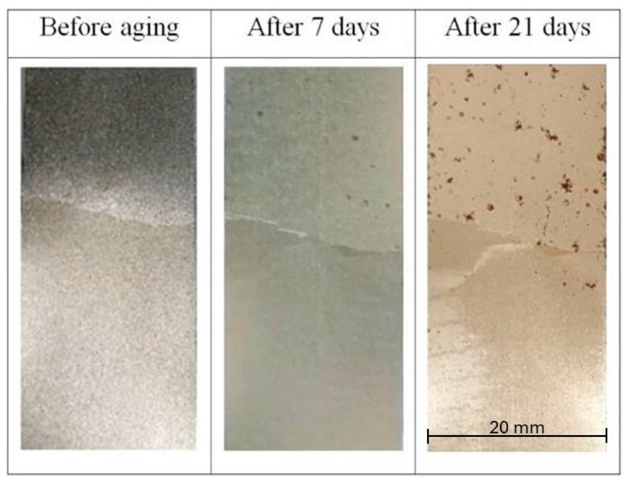
2.3. Corrosion Resistance

In order to test the corrosion resistance of the applied layers, the samples were placed in a climatic chamber MKFT-115 (Binder, Tuttlingen, Germany), at a temperature of 120 °C and a humidity of 45% RH, which creates a fully saturated environment. Samples measuring 7 × 2 cm were half-coated with binder, dried, and then hung on a stand in the chamber. The test was performed for 30 days, and the results were evaluated after 15 and 30 days.

2.4. Dielectric Properties

The dielectric properties of the binders were tested in a capacitor-like structure, amorphous steel ribbon/binder layer/silver electrode, which was described in the authors’ previous work [23].
A Broadband Dielectric Spectrometer with an Alpha-A High Performance Frequency Analyzer (Novocontrol Technologies, Montabaur, Germany) was used for the measurements, in which the samples were placed between two copper electrodes and inside a temperature-controlled sample cell, and the sample location in the device is presented in [23].
The complex permittivity can be represented by the equation below:
ε * f = ε f + ε ( f )
where:
  • ε*(f)—complex permittivity [F/m],
  • ε′(f)—real part of complex permittivity [F/m],
  • ε″(f)—imaginary part of complex permittivity [F/m].
The measurements were performed in the temperature range of 25–100 °C with 25 °C step, in the frequency range of 10−2–107 and at an AC voltage of 3 V.

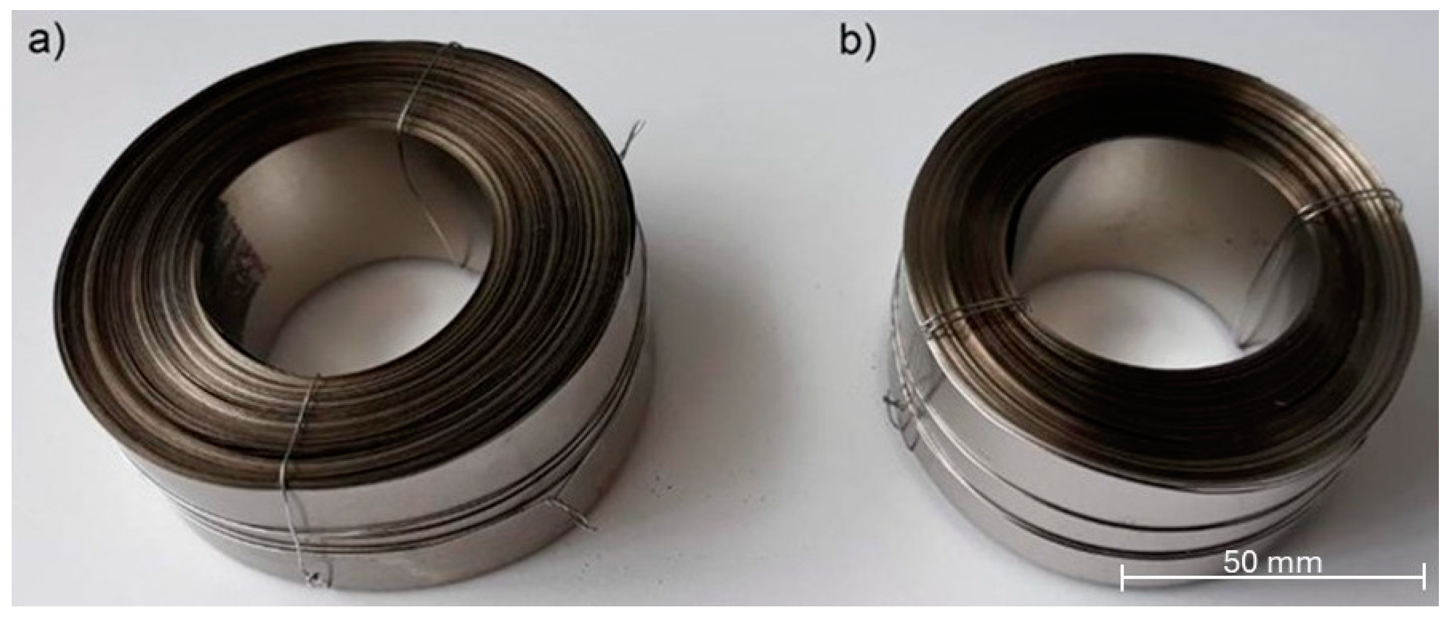
2.5. Model Toroidal Magnetic Core

In the main part of the research, magnetic cores from a 53 m long amorphous ribbon were prepared manually, one reference core and one with a hybrid binder applied. The first step consisted in degreasing the ribbon with acetone-soaked paper to remove surface impurities. The binder application was started by covering the amorphous ribbon with TEOS solution using a brush, and, after 15 min, BTSE solution was also applied with a brush and left for 30 min at room temperature. In the next step, the ribbon was wound and then dried in the same way as the samples in Section 2.2, in the following sequence: 4 h at 40 °C and 1 h at 320 °C. The drying procedure was conducted in an oven and in an air atmosphere, at a heating rate of 10°/min. All core preparation steps were the same—amount of ribbon used (53 m each), unwinding, pretreatment with acetone, winding, and annealing—the only difference being the presence of the binder between the subsequent turns of the ribbon in one core. Cores prepared in this way were tested for magnetic losses and audible noise. To investigate only the influence of binder application, the reference core was heat-treated in a similar way. The final appearance of the cores is presented in Figure 1.

2.6. Magnetic Measurements

To determine the hysteresis loop, remanence Br, coercivity Hc, saturation values Hs, Bs, and magnetic losses, the AMH-1M-S Permeameter (Laboratorio Elettrofisico, Nerviano, Italy) was used. It is an automatic DC and AC measuring system suitable for the evaluation of soft magnetic strips and metal rings with high resolution. Before the test, a primary set of NH turns (drive) must be wound around the sample, and a secondary set of NB turns (sense) must be applied to detect the magnetic flux. The arrangement of turns on the toroidal cores were similar to that presented in [23]. The field H(t) is calculated after measuring the current in the primary winding I(t):
H t = N H · I ( t ) l m
where:
  • H(t)—magnetizing force [A/m],
  • NH—number of turns,
  • I(t)—current [A],
  • lm—mean magnetic path length [m].
If the outer diameter of the core De is not greater than 10% of the inner diameter Di, the value of lm can be calculated using the following equation:
l m = π ( D e + D i ) 2
In other case, lm can be calculated as follows:
l m = π D e D i ln ( D e / D i )
To measure the current, the voltage across a low-inductance resistance is determined, and then the magnetic flux Φ is calculated after notification level of the voltage V(t) in the secondary winding:
Φ = V t d t
At the end, magnetic induction B is received by the following relationship:
B = Φ N B · A
where A is a cross-section of the core.

2.7. Noise Emission

Sound Pressure Level (SPL) measurements with time-domain recording and frequency analysis were performed using an SVAN 958 analyzer (Svantek, Warsaw, Poland). The magnetic core was powered by an AC Power supply PCR 1000 LA (Kikusui, Yokohama, Japan), and a 4054 oscilloscope (Tektronix, Beaverton, OR, USA) was used to analyze the quality of the power delivered to the core. The microphone was placed 30 cm above the object, and the core was placed on a reflecting floor equipped with a vibro-isolating rubber-cork mat. This approach prevents any parasitic noise from contacting the floor. The acoustic test setup was the same as presented in the authors’ previous work [23].

3. Results

Corrosion resistance and dielectric measurements were evaluated for a TEOS/BTSE binder partially deposited on an amorphous steel ribbon, while magnetic measurements and a noise analysis were performed on a model toroidal core, as shown in Figure 1.

3.1. Corrosion Resistance

In order to conduct thermal aging in an atmosphere saturated with water vapor, an amorphous steel ribbon coated with a TEOS/BTSE binder, and dried and annealed, was placed in a climatic chamber. After continuous exposure to atmospheric factors, the samples were taken out for testing and the results are presented in Figure 2.
It can be seen that, after a week of aging, corrosion has started at several points in the untreated steel ribbon area, while the binder-coated part remains clean without visible corrosion. More significant changes can be observed in the case of the sample aged for three weeks. A clear difference can be seen between the coated areas (unaffected clear surface) and the untreated areas (large number of corrosion spots). This effect indicates that the binder used improves the corrosion resistance of the amorphous steel ribbon; hence, both the service or shelf life of the treated ribbon can be extended, and, as a result, the electrical device using the bonded ribbon will be more resistant to the corrosion phenomenon.

3.2. Dielectric Properties

Samples for dielectric tests were prepared in a similar way to samples for a corrosion resistance test. A temperature range from 25 °C to 100 °C was selected due to the fact that electrical devices for indoor applications most often operate in such environmental conditions. The values of the dielectric constant depending on the frequency of the applied voltage and the measurement temperature are presented in Figure 3.
The dielectric constant shows a decreasing trend for all the investigated temperatures, and it can observed that the decrease is rapid at lower frequency values and less significant and constant at higher frequency values. The observed phenomenon, namely, the decrease in the dielectric constant value with the increase in the applied voltage frequency, is a typical dielectric behavior commonly found in the literature [37,38].
The investigated ceramic bonding layer can be considered as a heterogeneous material that can undergo interfacial polarization according to the Maxwell–Wagner theory, which indicates that, in the low-frequency region, the movement of charge carriers trapped in the interfacial region is caused by the inhomogeneous dielectric structure [39]. On the other hand, at high frequencies, the leading mechanism responsible for the dielectric constant behavior is the hopping mechanism under the influence of the AC current. The hopping frequency between ions cannot follow the frequency of the applied electric field; therefore, the dielectric constant values decrease at a higher frequency [40].
The observed temperature dependence on the dielectric constant can be explained by the influence of several factors, such as the following:
  • the effect of volumetric thermal expansion;
  • the effect of temperature on polarizability [41].
From the application point of view in electrification devices, the most important are the values of the dielectric constant at 50 Hz and 60 Hz. Figure 3 shows that it varies from 6.7 to 6.9 depending on the temperature, so there is no significant influence of temperature. This behavior can be explained by the fact that the measured coefficient of thermal expansion for the sol layers is very small [23]. Therefore, the measured values of the dielectric constant in the selected temperature range make the investigated bonding material suitable for application as a dielectric separation layer between wound amorphous steel ribbons with the potential to be used in electrical devices.

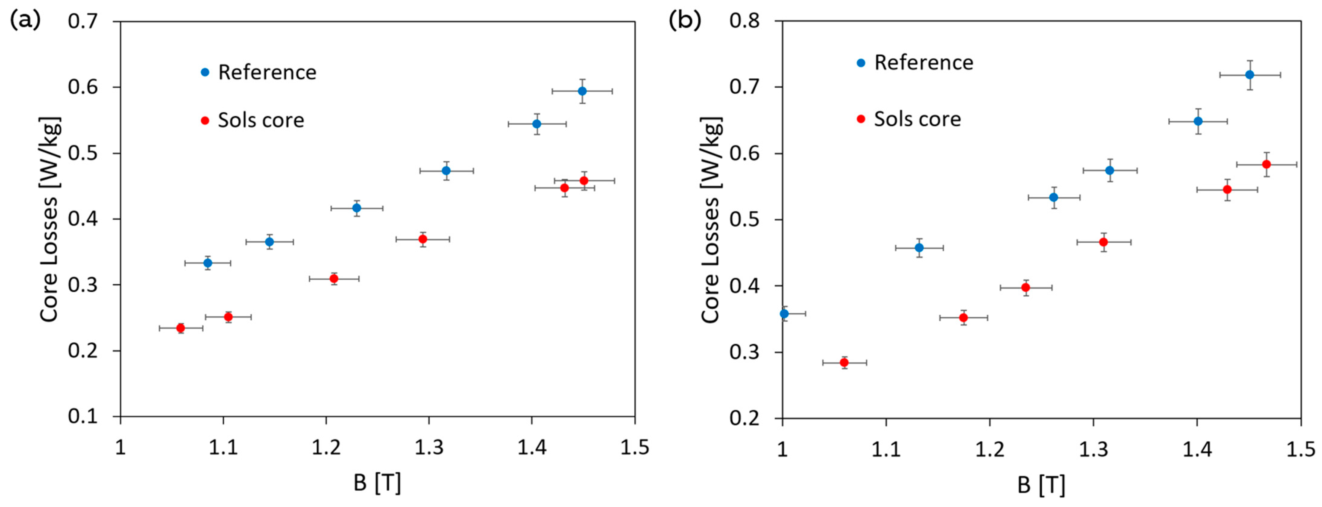
3.3. Magnetic Properties
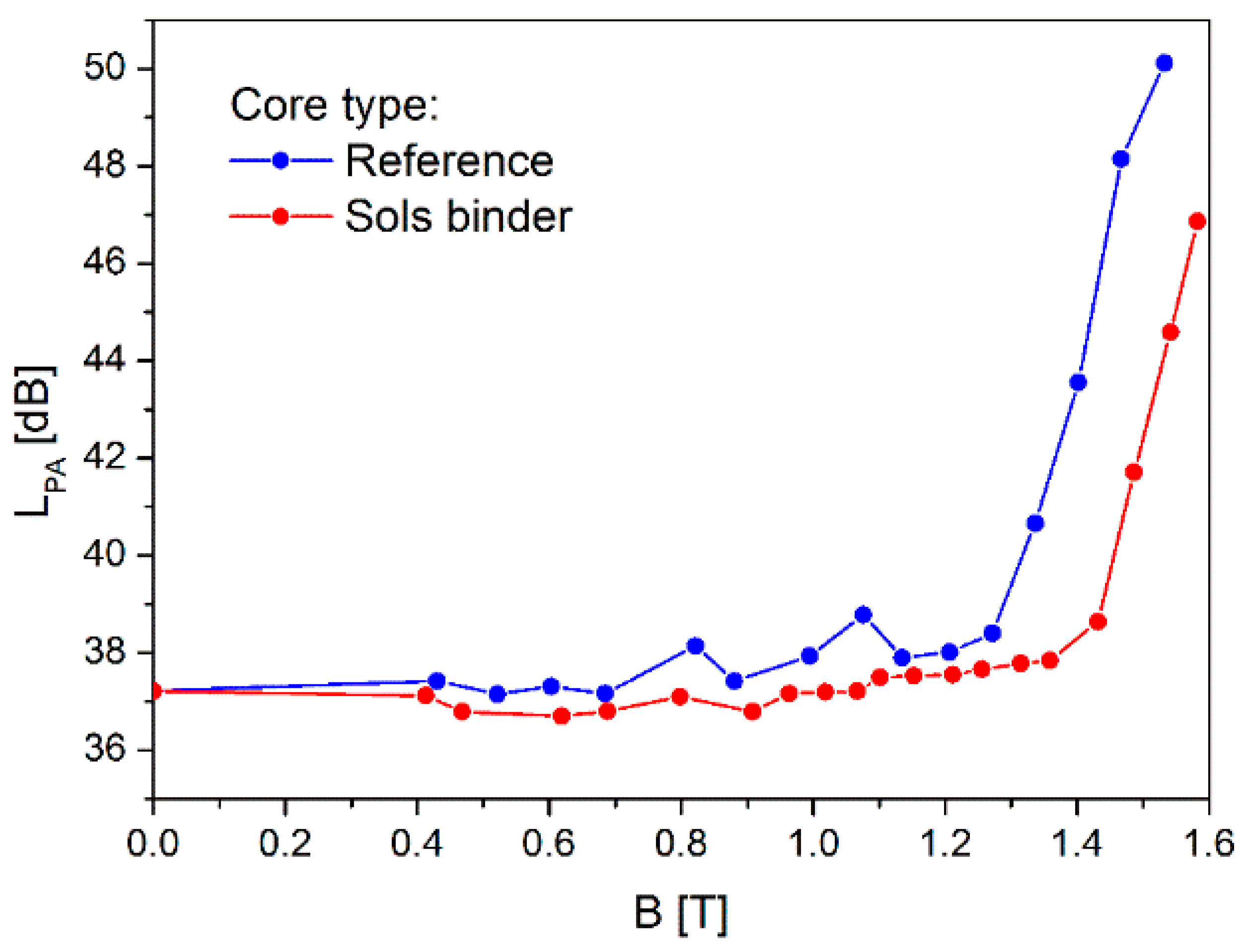
One of the key parameters describing the properties of the magnetic core are its no-load losses; hence, this parameter was investigated for the tested cores and the measurement results are shown in Figure 4 for the excitation power supply with a frequency of 50 Hz and 60 Hz.
The alternating magnetic flux flowing through the core induces voltage and current not only in the secondary winding but also in the core itself, resulting in an eddy current. The eddy current generates a magnetic flux that interrupts the magnetic flux in the core and it can be generated not only within individual lamination (ribbon), but also in the core stack as a so-called interlaminar eddy current [8]. Therefore, the use of the developed bonding material with good dielectric properties can lead to an effective reduction in eddy current losses.
The measurement results indicate that, in the case of a magnetic core bonded with silane sols, the core loss values are significantly lower than for the reference core. At the saturation level (around 1.5 T), the recorded losses are 23% lower at 50 Hz, while they are 19% lower at 60 Hz. It can, therefore, be concluded that the application of a sol-based binder on the surface of an amorphous steel ribbon enables the formation of a well-defined dielectric layer that not only acts as a bonding material but also efficiently reduces core losses.

3.4. Noise Emission

The magnetic core under test was placed on a cork mat in the center of the room, where the background sound pressure level measured with the magnetic core de-energized (at the magnetic flux 0 T) was about 37 dB. Then, the equivalent continuous sound pressure levels were evaluated during core excitation from 0.4 T to the saturation flux density at 50 Hz, which is the characteristic operating frequency for distribution transformers. The same procedure was used to measure the noise of the reference, not the bonded core. The obtained results are shown in Figure 5.
It is clearly visible that, in the case of the core bonded with sols, the noise starts to go beyond the background level for a much higher operating flux density than for the reference core, 1.4 T compared to 1.25 T, respectively. This means that the reference core starts to be noisy at a much lower operating load than the core bonded with sols. The observed effect can be explained by the counteraction of the applied sol-based bonding layers against the magnetostriction of amorphous steel [16]. Due to the applied bonding, the core vibrations caused by the magnetic forces between the laminations are being decreased, as a result of which the core noise also decreases. It is also worth noting that, at a saturation flux of about 1.5 T (saturation), the difference in noise levels between the reference core and the bonded core is 6 dB, which means that the reference core is twice as noisy as the bonded core.
Additional confirmation of the noise reduction effectiveness due to the applied bonding system is clearly visible in the frequency spectrum of the sound pressure levels in the range from 100 Hz to 10 kHz, which is presented in Figure 6.
The spectrum shown clearly shows that, in most of the peaks in the frequency domain, the sound pressure amplitudes for the core bonded with sols are much lower than for the reference core, which is particularly visible for the frequencies of 400 Hz and 1 kHz, and harmonic frequencies of 1.1 kHz, 1.2 kHz, etc.

4. Conclusions

The analysis of the obtained results indicates that the main goal of this work, which was to confirm that the hybrid binder based on tetraethoxysilane and 1,2-bis(triethoxysilyl)ethane can successfully consolidate the transformer core made of a Metglas amorphous steel ribbon, has been achieved. It has been proven that the metal substrate coated with the hybrid binder has a higher corrosion resistance compared to the raw amorphous metal; therefore, the service life of the treated ribbon can be extended. It has been shown that the dielectric constant of the sol-based hybrid binder layer shows a decreasing tendency at higher frequencies for all tested temperatures (25, 50, 75, and 100 °C), and, at the most interesting frequencies, namely, 50 Hz and 60 Hz, the dielectric constant fluctuates slightly in the range of 6.7–6.9, which indicates no significant influence of temperature. Furthermore, the results showed that, over the entire operating flux density range (1–1.5 T) and at both tested frequencies (50 Hz and 60 Hz), the core bonded with a silane-based binder exhibits significantly lower core losses compared to the unbonded reference core. At saturation flux (about 1.5 T) and 50 Hz, the bonded core losses are 23% lower than the reference core losses, while, at 60 Hz, the reduction is 19%. The literature shows that the interlaminar application of an organic metallic binder results in a core loss reduction of up to 26% compared to the edge-glued core with the epoxy resin [16]. When the bonding powder was applied on the edge of the core by plasma-arc spraying, the core loss reduction was only 11–15% compared to the untreated core [17].
The noise analysis in our study shows that the sol-bonded magnetic core becomes noisy above 1.4 T, while the reference already exceeds the background sound level at 1.25 T. The difference at the saturation flux (approximately 1.5 T) is 6 dB, which means that the reference core is two times noisier than the bonded core. In addition, the sound pressure level in the range from 100 Hz to 10 kHz is generally lower for the sol-bonded core compared to the reference core. Kmita at al. showed in [16] that changing the epoxy binder at the core edge to an organometallic binder between the core laminations reduces the sound power by 21% at 50 Hz and 1.35 T. Interesting results can be found in [21], where three types of cores were tested, one in which the laminations were tied around with tape, the second glued with the epoxy resin on the edge, and the third a reference one without any bonding. Surprisingly, it can be noted that the reinforcement of the core did not reduce the audible noise, and, so, in the case of the tape-bonded core, the sound power was slightly higher than in the case of the reference core, while the core glued with epoxy resin had an average noise higher by 10 dB.
Taking into account all the above conclusions, it is evident that the proposed hybrid binder based on the double-layer TEOS/BTSE system can be successfully applied to the magnetic core made of an amorphous metal ribbon. This is valuable information from the application point of view, as it opens the possibility of producing a more efficient transformer core, which is also characterized by a reduced level of emitted audible noise. It should be emphasized that the applied conditions, such as manual core preparation, sol application, and drying in an air atmosphere, and being below the Curie temperature allowed us to conclude that the scaling process of this technology should be successful. Moreover, the introduction of automated process elements, such as unwinding/winding, as well as pulling the ribbon through acetone and sol solutions at a well-defined speed, should provide even better core properties, because the obtained layers will be more uniform.

Author Contributions

Conceptualization, A.R. and G.K.; methodology, A.R., M.S. and J.N.; validation, J.N. and A.R.; formal analysis, J.N., M.K. and S.P.; investigation, J.N., M.K. and S.P.; data curation, A.R. and J.N.; writing—original draft preparation, J.N. and A.R.; writing—review and editing, A.R., M.S. and G.K.; visualization, J.N. and A.R.; supervision, A.R and M.S. All authors have read and agreed to the published version of the manuscript.

Funding

This work was supported by the subsidy of the Ministry of Education and Science for the AGH University of Science and Technology in Kraków (Project No 16.16.160.557).

Institutional Review Board Statement

Not applicable.

Informed Consent Statement

Not applicable.

Data Availability Statement

The data presented in this study are available upon request from the corresponding author.

Conflicts of Interest

Authors Jolanta Nieroda, Grzegorz Kmita, Michal Kozupa, and Andrzej Rybak were employed by the company “ABB Corporate Technology Center, Krakow”. Authors Grzegorz Kmita, Michal Kozupa, and Szymon Piela were employed by the company “Hitachi Energy Research, Krakow”. The remaining authors declare that the research was conducted in the absence of any commercial or financial relationships that could be construed as a potential conflict of interest.

Abbreviations

The following abbreviations are used in this manuscript:
TEOStetraethyl orthosilicate
BTSE1,2-bis(triethoxysilyl)ethane
CTEcoefficient of thermal expansion
ACalternating current

References

  1. Du, J.; Rasool, Y.; Kashif, U. Asymmetric Impacts of Environmental Policy, Financial, and Trade Globalization on Ecological Footprints: Insights from G9 Industrial Nations. Sustainability 2025, 17, 1568. [Google Scholar] [CrossRef]
  2. Borowski, P.F. Economic and Technological Challenges in Zero-Emission Strategies for Energy Companies. Energies 2025, 18, 898. [Google Scholar] [CrossRef]
  3. Chen, M.; Yu, Y.J.; Xiao, L.Y.; Wang, Q.L.; Chung, W.; Kim, K.; Baang, S. The Magnetic Properties of the Ferromagmetic Materials Used for HTS Transformers at 77K. IEEE Trans. Appl. Supercond. 2003, 13, 2313–2316. [Google Scholar] [CrossRef]
  4. Kurt, E.; Hatem, S. Design and Implementation of a MHz Frequency Transformer with a Ferromagnetic Fluid Core. Sustainability 2023, 15, 23. [Google Scholar] [CrossRef]
  5. Sima, W.; Liu, Y.; Sun, P.; Zhou, Y.; Peng, D.; Yang, M. The Effect of Different Core Materials on Transformer Inrush Currentsm. In Proceedings of the 2018 IEEE International Magnetics Conference (INTERMAG), Singapore, 23–27 April 2018. [Google Scholar]
  6. Heathcote, M.J. J&P Transformer Book, 12th ed.; Newnes: Oxford, UK, 1998; pp. 40–102+422–444. [Google Scholar]
  7. Molnar, A.; Smith, G.V.; Bartok, M. New Catalytic Materials from Amorphous Metal Alloys. Adv. Catal. 1989, 36, 329–383. [Google Scholar]
  8. McLyman, C.W.T. Transformer and Inductor Design Handbook, 4th ed.; CRC Press: Boca Raton, FL, USA, 2011; Volume 1, p. 11. [Google Scholar]
  9. Kronmuller, H.; Fahnle, M.; Domann, M.; Grimm, H.; Grimm, R.; Groger, B. Magnetic properties of amorphous ferromagnetic alloys. J. Magn. Magn. Mater. 1979, 13, 53–70. [Google Scholar] [CrossRef]
  10. Ramanan, V.R.V.; Smith, C.H.; Fish, G.E. Metallic glasses in magnetic applications. Key Eng. Mater. 1987, 13–15, 849–861. [Google Scholar] [CrossRef]
  11. Azuma, D.; Hasegawa, R. Core Loss in Toroidal Cores Based on Fe-Based Amorphous Metglas 2605HB1 Alloy. IEEE Trans. Magn. 2011, 47, 3460–3462. [Google Scholar] [CrossRef]
  12. Sato, T.; Yamada, T. Improvement of core loss by chemical thinning in a thick amorphous alloy ribbon. IEEE Trans. Magn. 1972, 28, 2775–2777. [Google Scholar] [CrossRef]
  13. Distribution Goes Green. Available online: https://library.e.abb.com/public/4b6d4b3cfd353a88c1257a25002696a8/ABB%20Review%202-2012_72dpi.pdf (accessed on 14 February 2025).
  14. Ramanan, V.R.V.; Pasquale, M.; Bertotti, G. The influence of microstructure on power losses in Fe-B-Si metallic glasses. J. Magn. Magn. Mater. 1994, 133, 362–365. [Google Scholar] [CrossRef]
  15. Luborsky, F.; Becker, J.; McCary, R. Magnetic annealing of amorphous alloys. IEEE Trans. Magn. 1975, 11, 1644–1649. [Google Scholar] [CrossRef]
  16. Kmita, G.; Sekula, R.; Rybak, A.; Kozupa, M.; Klys, P. Method of Manufacturing an Amorphous Magnetic Core and Amorphous Magnetic Core. European Patent Application No. EP3035351B1, 20 February 2019. [Google Scholar]
  17. Grimes, F.H.; Krause, R.F. Methods of Consolidating a Magnetic Core. U.S. Patent Application No. US4615106A, 7 October 1986. [Google Scholar]
  18. Goldman, I.; Grant, T.W.; Grote, J.K.; Collins, R.L.; Houser, K. Edge Bonding for Amorphous Metal Transformer. U.S. Patent Application No. US6413351B1, 2 July 2002. [Google Scholar]
  19. Verbunt, J.P.M. Lamellar Magnetic Core Utilizing Low Viscosity Epoxy Adhesive. U.S. Patent Application No. US4713297A, 15 December 1987. [Google Scholar]
  20. Lupinski, J.H. Bonded Amorphous Metal Electromagnetic Components. U.S. Patent Application No. US4201837A, 6 May 1980. [Google Scholar]
  21. Columbus, M.R.; Brown, R.; Takahashi, K.; Hasegawa, R. Method of Reducing Audible Noise in Magnetic Cores and Magnetic Cores Having Reduced Audible Noise. U.S. Patent Application No. US8427272B1, 23 April 2013. [Google Scholar]
  22. Nieroda, J.; Kmita, G.; Kozupa, M.; Piela, S.; Rybak, A. The Use of Polyimide as a Bonding Material to Improve the Mechanical Stability, Magnetic and Acoustic Properties of the Transformer Core Based on Amorphous Steel. Polymers 2024, 16, 1840. [Google Scholar] [CrossRef]
  23. Nieroda, J.; Rybak, A.; Kmita, G.; Niziol, J.; Gondek, E.; Sitarz, M. Synthesis and characterization of silane based binder for the amorphous metal ribbon. Thin Solid Film. 2020, 716, 138433. [Google Scholar] [CrossRef]
  24. Dral, A.P.; Tempelman, K.; Kappert, E.J.; Winnubst, L.; Benes, N.E.; ten Elshofa, J.E. Long-term flexibility-based structural evolution and condensation in microporous organosilica membranes for gas separation. J. Mater. Chem. A. 2017, 5, 1268–1281. [Google Scholar] [CrossRef]
  25. Nitta, S.V.; Pisupatti, V.; Jain, A.; Wayner Jr, P.C.; Gill, W.N.; Plawsky, J.L. Surface modified spin-on xerogel films as interlayer dielectrics. J. Vac. Sci. Technol. B 1999, 14, 205–212. [Google Scholar] [CrossRef]
  26. Zhao, J.H.; Ryan, T.; Ho, P.S.; McKerrow, A.J.; Shih, W.Y. Measurement of elastic modulus, Poisson ratio, and coefficient of thermal expansion of on-wafer submicron films. J. Appl. Phys. 1999, 85, 6421–6424. [Google Scholar] [CrossRef]
  27. Dalmoroa, V.; dos Santos, J.H.Z.; Armelin, E.; Aleman, C.; Azambuja, D.S. A synergistic combination of tetraethylorthosilicate and multiphosphonic acid offers excellent corrosion protection to AA1100 aluminum alloy. Appl. Surf. Sci. 2013, 273, 758–768. [Google Scholar] [CrossRef]
  28. Ramezanzadeh, B.; Raeisi, E.; Mahdavian, M. Studying various mixtures of 3-aminopropyltriethoxysilane (APS) and tetraethylorthosilicate (TEOS)silanes on the corrosion resistance of mild steel and adhesion properties of epoxy coating. Int. J. Adhes. Adhes. 2015, 63, 166–176. [Google Scholar] [CrossRef]
  29. Atanacio, A.J.; Latella, B.A.; Barbe, C.J.; Swain, M.V. Mechanical properties and adhesion characteristics of hybrid sol–gel thin films. Surf. Coat. Tech. 2005, 192, 354–364. [Google Scholar] [CrossRef]
  30. Khramov, A.N.; Balbyshev, V.N.; Kasten, L.S.; Mantz, R.A. Sol–gel coatings with phosphonate functionalities for surface modification of magnesium alloys. Thin Solid Film. 2006, 514, 174–181. [Google Scholar] [CrossRef]
  31. Batan, A.; Brusciotti, F.; De Graeve, I.; Vereecken, J.; Wenkin, M.; Piens, M.; Pireaux, J.; Reniers, F.; Terryn, H. Comparison between wet deposition and plasma deposition of silane coatings on aluminium. Prog. Org. Coat. 2010, 69, 126–132. [Google Scholar] [CrossRef]
  32. Ciobotaru, I.A.; Vaireanu, D.I.; Ciobotaru, I.E.; Barbu, O.C. The Influence of the Curing Temperature on the Properties of Some Silane Films. Rev. Chim-Buchar. 2017, 78, 1413–1418. [Google Scholar] [CrossRef]
  33. Nieroda, J.; Mastalska-Poplawska, J.; Rybak, A.; Sitarz, M. Spectroscopic and rheological investigation of candidates for the double-layered binder for amorphous metal ribbon. J. Mol. Struct. 2020, 1207, 127763. [Google Scholar] [CrossRef]
  34. Farad, M.A. Catalysts and the structure of SiO2 sol-gel films. J. Mater. Sci. 2000, 35, 1835–1841. [Google Scholar] [CrossRef]
  35. Franquest, A.; Biesemans, M.; Willem, R.; Terryn, H.; Vereecken, J. Multinuclear 1D- and 2D-NMR study of the hydrolysis and condensation of bis-1,2-(trie triethoxysilyl) ethane. J. Adhes. Sci. Technol. 2004, 18, 765–778. [Google Scholar] [CrossRef]
  36. Van Schaftinghen, T.; Le Pena, C.; Terryn, H.; Horzenberger, F. Investigation of the barrier properties of silanes on cold rolled steel. Electrochim. Acta 2004, 49, 2997–3004. [Google Scholar] [CrossRef]
  37. Mahmoudi, C.H.; Hassanzadeh, A.; Golzan, M.M.; Sedgh, H.; Talebian, M. Frequency dependence of ultrahigh dielectric constant of novel synthesized SnO2 nanoparticles thick films. Curr. Appl. Phys. 2011, 11, 409–413. [Google Scholar] [CrossRef]
  38. Venkataraman, B.H.; Varma, K.B.R. Frequency-dependent dielectric characteristics of ferroelectric SrBi2Nb2O9 ceramics. Solid State Ion. 2004, 167, 197–202. [Google Scholar] [CrossRef]
  39. Kremer, F.; Schönhals, A. Broadband Dielectric Spectroscopy; Springer: Berlin/Heidelberg, Germany; New York, NY, USA, 2003; pp. 188–199. [Google Scholar]
  40. Alias, R. Ceramic Substrate with Varied Sintering Temperatures, in Sintering Applications. In Structural and Dielectric Properties of Glass; Ertung, B., Ed.; IntechOpen: Rijeka, Croatia, 2013; pp. 89–118. [Google Scholar]
  41. Havinga, E.E. The temperature dependence of dielectric constants. J. Phys. Chem. Solids 1961, 18, 253–255. [Google Scholar] [CrossRef]
Figure 1. Toroidal magnetic cores: (a) bonded with sols, and (b) reference.
Applsci 15 05141 g001
Figure 2. Images of samples coated partially with a silane-based hybrid binder before and after aging in a climatic chamber. The lower half was coated with the binder, while the upper half was left untreated.
Applsci 15 05141 g002
Figure 3. Variation in the real part (e′) of the dielectric permittivity as a function of frequency at various temperatures for a sol-based hybrid binder layer.
Applsci 15 05141 g003
Figure 4. Core losses as a function of operating flux density for toroidal cores: reference and bonded with silane-based sols. Measurement performed at a frequency of (a) 50 Hz and (b) 60 Hz.
Applsci 15 05141 g004
Figure 5. Sound pressure levels at 50 Hz operating frequency as a function of flux density measured for the reference and the sol-bonded core.
Applsci 15 05141 g005
Figure 6. Frequency spectrum of sound pressure level for the reference core and the core bonded with sols, for the cores which were excited with a magnetic flux of 1.54 T (saturation), at a frequency of 50 Hz.
Applsci 15 05141 g006
Disclaimer/Publisher’s Note: The statements, opinions and data contained in all publications are solely those of the individual author(s) and contributor(s) and not of MDPI and/or the editor(s). MDPI and/or the editor(s) disclaim responsibility for any injury to people or property resulting from any ideas, methods, instructions or products referred to in the content.

