Article

Research on the Stability of UAV Attitude Under Hybrid Control Integrating Active Disturbance Rejection Control and Super-Twisting Sliding Mode Control

1
Institute of Interdisciplinary Technology, Shenyang University, Shenyang 110044, China
2
College of Intelligent Science and Information Engineering, Shenyang University, Shenyang 110000, China
3
College of Mechanical Engineering, Shenyang University, Shenyang 110044, China
*
Author to whom correspondence should be addressed.
Appl. Sci. 2025, 15(9), 5124; https://doi.org/10.3390/app15095124
Submission received: 27 March 2025 / Revised: 26 April 2025 / Accepted: 3 May 2025 / Published: 5 May 2025

Abstract

:
In response to the inherent nonlinearity and complex coupling of quadrotor UAV systems, as well as the challenge of maintaining a stable flight attitude under external disturbances, this paper proposes a UAV pose control method based on a fusion of Active Disturbance Rejection Control (ADRC) and Super-Twisting Sliding Mode Control (ST-SMC). By combining the strengths of ADRC and the super-twisting sliding mode algorithm, this approach achieves complementary performance—enhancing the system’s disturbance rejection capability and response speed while effectively mitigating the high-frequency chattering problem commonly caused by switching functions in traditional sliding mode control. Under random airflow disturbances, the designed fusion algorithm leverages the dynamic compensation characteristics of ADRC to stabilize external perturbations, while the robustness of ST-SMC suppresses the effects of system nonlinearities and uncertainties on control accuracy. Finally, MATLAB simulation experiments validate the effectiveness of this method, showing significantly better performance in terms of response speed, overshoot, and settling time compared to traditional control algorithms. This approach greatly improves the UAV’s pose stability and self-balancing capability in complex environments, ensuring strong dynamic and static control performance under random disturbances while maintaining high real-time performance and control efficiency.

1. Introduction

The rapid evolution of Unmanned Aerial Vehicle (UAV) technology has propelled quadrotor platforms into ubiquitous utilization across military, agricultural, and logistical domains. Nevertheless, operational deployment of these systems frequently exposes them to stochastic environmental perturbations, with unsteady aerodynamic disturbances posing significant challenges to flight stability. Investigating attitude control mechanisms under such disturbances is critical for enhancing operational robustness and maneuverability in dynamically complex scenarios. Algorithmic advancements enable UAVs to dynamically compensate for destabilizing forces through rapid response and adaptive adjustments, thereby ensuring mission-critical safety. Recent progress in modern control theory, particularly in nonlinear and time-varying system analysis, has provided rigorous frameworks for addressing the inherent complexities of quadrotor dynamics—characterized by nonlinear dynamics, strong coupling effects, and under-actuation characteristics—offering enhanced theoretical foundations for precision control implementations.
To investigate the impact of external disturbances on UAVs, the main current control methods include PID [1,2,3,4,5,6], backstepping [7,8,9,10,11], and sliding-mode control [4,5,6,7,8,9,10,11,12,13,14]. Wang et al. [15] introduced a particle swarm optimization algorithm to adjust the parameters of the PID controller, optimizing system performance. Simulation results indicated that their optimization method was effective and reasonable. Chen [16] designed a dual-loop controller based on the PID algorithm for position and attitude control, respectively, after establishing the dynamics model of the quadrotor UAV. Flight experiments verified the reliability and effectiveness of this design. In recent years, research on PID control has also included its integration with other control methods to enhance system adaptability and control precision. For instance, by combining fuzzy control or neural network technology, PID control can achieve adaptive parameter adjustment in dynamic environments, thereby better coping with flight missions under complex disturbance conditions. These improvements have expanded the application scenarios of PID control, enabling it to play a greater role in the precise control of quadrotor UAVs.
Li [17] designed an attitude and position controller for quadrotor UAVs based on the backstepping method. Simulation results indicated that this approach exhibited strong adaptability in addressing the uncertainty associated with load variations and could effectively suppress external airflow disturbances, thereby enhancing the stability and robustness of the aircraft. However, the method also had limitations. For instance, it was sensitive to initial conditions. If the initial conditions deviate from the expected range, the performance of the controller might be affected. Lian [18] proposed an adaptive fault-tolerant controller based on second-order fast nonsingular terminal sliding-mode control to ensure flight stability and smooth landing in the event of a single-rotor failure in quadrotor UAVs. The author effectively eliminated chattering in the control output through the second-order sliding-mode control method while maintaining rapid response and high-precision trajectory-tracking capabilities. Moreover, the author discussed the impact of the rotation axis and the norm of the angular velocity on dynamic tracking performance and proposed improvement strategies, especially for performance enhancement in cases of a large moment of inertia. Experiments verified the feasibility and tracking performance of the controller. However, since this controller relied on the optimization of multiple parameters, the selection of these parameters required a trade-off between rapid response and precise tracking. This process was extremely time-consuming and complex, posing high demands on the computational capacity of the processor. Jiang [19] analyzed the closed-loop control system of UAVs and used the non-parametric prediction error estimation method to identify the actuator module, proving that the identified model was unbiased compared to the actual model. A safety controller was designed based on the identified model, and the connotation of UAV safety was elucidated. However, the paper lacked an in-depth discussion on the principle and applicable scenarios of the non-parametric prediction error estimation method and did not consider the impact of various complex environmental factors on the performance of the controller. Urbina-Brito [20] proposed a Model Predictive Control (MPC)-based strategy to address the control problem of Unmanned Aerial Vehicles (UAVs) carrying suspended loads. The study established a nonlinear dynamic model of the system using the Euler–Lagrange method and then linearized it to design the MPC controller. This controller simultaneously considers the UAV’s translational and rotational dynamics in three-dimensional space, as well as the swinging dynamics of the suspended load. Through constrained optimization, it achieves a fast and stable balance with minimal swing angles. Numerical simulations verified the effectiveness of the controller, demonstrating superior performance compared to nonlinear control methods presented in previous literature.
Guerrero-Sánchez [21] proposed a hierarchical control strategy that combines Energy-Based Control (EBC) with a nonlinear state feedback controller based on Linear Matrix Inequalities (LMIs) to address the control problem of Unmanned Aerial Vehicles (UAVs) carrying suspended loads. The study established a nonlinear dynamic model of the system using the Euler–Lagrange method and designed two controllers: the EBC is used to stabilize the UAV’s translational dynamics and suppress load swing, while the LMI-based controller is applied to manage the UAV’s rotational dynamics. The innovation of this approach lies in its ability to avoid solving complex partial differential equations and its capability to handle large Lipschitz constants.
Gui [22] proposed a sliding-mode attitude control method for quadrotor UAVs based on a Nonlinear Expanded State Observer (NESO) and a Low-Frequency Disturbance compensator (LFDC), aiming to address the complex aerodynamic characteristics and susceptibility to interference in UAV attitude control. By combining NESO and LFDC in the inner loop, the author could more accurately estimate and compensate for the low-frequency components of the total disturbance. The outer loop used a nonsingular fast terminal sliding-mode controller with a Tracking Differentiator (TD) and variable switching gain, effectively compensating for the errors in the virtual disturbance estimate and the high-frequency components of the total disturbance, thereby enhancing the system’s anti-interference capability and response speed. Simulation results showed that this method outperformed traditional control methods in terms of anti-interference and attitude-tracking performance. However, this method lacked consideration for unmodeled external disturbances, such as random airflow disturbances, which might affect the stability and tracking precision of the controller.
By analyzing the shortcomings of the aforementioned reference articles, this paper addresses the technical challenge of achieving stable control for Unmanned Aerial Vehicles (UAVs) operating in complex nonlinear systems and under random airflow disturbances. A hybrid control algorithm is proposed, integrating Active Disturbance Rejection Control (ADRC) with Super-Twisting Sliding Mode Control (ST-SMC). This algorithm leverages the advantages of ADRC in disturbance estimation and compensation, as well as the strengths of ST-SMC in enhancing system robustness and suppressing high-frequency chattering, thereby achieving complementary improvements in control performance. The hybrid algorithm effectively mitigates external disturbances, reduces system oscillations, and significantly enhances the accuracy and stability of attitude and trajectory control. Simulation results demonstrate that the algorithm exhibits strong disturbance rejection and fast convergence during the dynamic response phase. Even under strong airflow disturbances, the UAV can quickly return to the desired trajectory.
To better illustrate the proposed approach, the paper is divided into five sections. The first section establishes the UAV model. The second section presents the improved control algorithm, which adopts a fusion strategy of ADRC and ST-SMC to maintain stable flight and attitude under external disturbances. The third section proves the stability of the proposed method using Lyapunov theory. In the fourth section, simulations are conducted to verify the reliability of the method, and a comparison with traditional control algorithms highlights the superiority of the proposed approach. The final section provides conclusions.

2. Materials and Methods

Quadrotor UAV architectures are principally categorized into cross-type (QUAD+) and X-type (QUAD X) configurations, with this study employing the X-type topology for platform development, as schematically illustrated in Figure 1. The propulsion system comprises four numerically designated coaxial rotors (M1–M4 sequenced left-to-right and top-to-bottom), generating aerodynamic forces through differential rotor speed regulation to achieve multi-axis control. Flight maneuvers—including vertical translation, forward/backward motion, roll, yaw, and pitch—are governed by specific actuation protocols detailed in Table 1. Vertical motion requires uniform throttle input across all rotors, whereas pitch control is implemented through coordinated acceleration of M1/M2 (denoted by “+”), paired with deceleration of M3/M4 (denoted by “−”), demonstrating the system’s capability to modulate thrust asymmetries for attitude adjustment.
To better understand how a drone flies, a SolidWorks 2019 structural diagram of a drone similar to the DJI Phantom series is shown below.

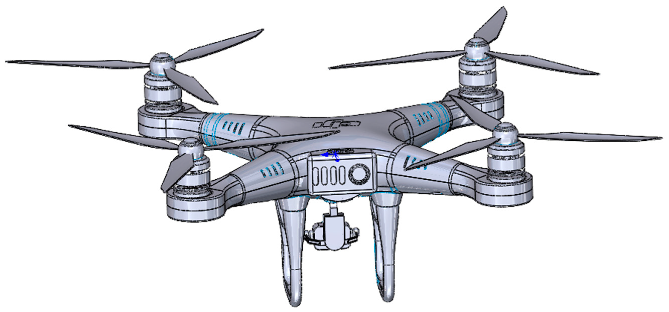
2.1. Translational Dynamics Model

The motion of the UAV’s center of mass, which is governed by mechanics, can be described as [23]:
p . = v
τ = L T 2 T 4 L T 3 T 1 C q ω 1 2 ω 2 2 + ω 3 2 ω 4 2
where p = [ x , y , z ] T represents the position vector of the UAV, v = v x , v y , v z T represents the velocity vector.
The rotation matrix R , which transforms the body-fixed coordinate system to the inertial coordinate system, is defined as:
R = R z ( ψ ) R y ( θ ) R x ( ϕ )
Among these, ϕ , θ , ψ denote the roll angle, pitch angle, and yaw angle of the unmanned aerial vehicle, respectively.
The rotation matrix is expanded as follows:
R = c θ c ψ c θ s ψ s θ s ϕ s θ c ψ c ϕ s ψ s ϕ s θ s ψ + c ϕ c ψ s ϕ c θ c ϕ s θ c ψ + s ϕ s ψ c ϕ s θ s ψ s ϕ c ψ c ϕ c θ
where c and s denote the cosine and sine functions, respectively.

2.2. Attitude Dynamics Model

The rotational dynamics of a UAV are based on Euler’s equations of motion for rigid bodies.
I ω ˙ + ω × ( I ω ) = τ + d a
where ω = [ p , q , r ] T represents the angular velocity (in the body frame), τ = τ ϕ , τ θ , τ ψ T denotes the control moment, and d a represents the disturbance terms. I is the inertia matrix of the unmanned aerial vehicle, as follows:
I = I x 0 0 0 I y 0 0 0 I z
The mapping relationship between the Euler angles η = [ ϕ , θ , ψ ] T and angular velocity ω is given by:
η ˙ = T η ω
where is the nonlinear mapping matrix between the Euler angles and angular velocity, as shown below:
T η = 1 s ϕ t θ c ϕ t θ 0 c ϕ s ϕ 0 s ϕ / c θ c ϕ / c θ
The UAV is affected by aerodynamic drag, and the aerodynamic forces are represented as:
F a = C d v
Here, C d is the drag coefficient matrix. Since the thrust generated by the propellers is proportional to the square of the motor speed, the thrust can be expressed as:
T = C t ω p 2
where ω p   represents the motor speed, and C t is the thrust coefficient.
The torque τ generated by the propellers is expressed as:
τ = L T 2 T 4 L T 3 T 1 C q ω 1 2 ω 2 2 + ω 3 2 ω 4 2
where L represents the arm length, C q is the torque coefficient, and T i   is the thrust generated by the i-th propeller.
The complete state–space model of the UAV is given by [24]:
x . = f ( x ) + g ( x ) u + d a
where x = [ p , v , η , ω ] T represents the UAV state, and u = T , τ ϕ , τ θ , τ ψ T denotes the control input, d a represents the disturbance.

2.3. Design of ADRC and ST-SMC Hybrid Control

The UAV is a highly nonlinear and complex coupled system, and when operating in dynamic environments such as random airflow disturbances, it demands higher standards for control strategies and algorithms. Traditional control algorithms, such as ADRC, significantly enhance the system’s disturbance rejection performance and dynamic response speed due to its built-in ESO, which estimates and compensates for external disturbances and system modeling errors in real time. However, ADRC has limitations when dealing with complex nonlinearities and strong uncertainties. In contrast, the ST-SMC algorithm, by improving the design of traditional sliding mode control, offers stronger robustness and disturbance rejection capabilities. It effectively reduces the high-frequency oscillations caused by the switching function in conventional sliding mode control algorithms. The ST-SMC not only tracks the system state more smoothly but also avoids energy consumption and instability issues resulting from multiple sliding surface switches during fast response processes. Therefore, this section integrates the advantages of ADRC and ST-SMC, enabling the controller to achieve complementary performance. Under random airflow disturbances, the combined algorithm leverages the dynamic compensation properties of ADRC to stabilize external disturbances, while the robustness of ST-SMC suppresses the impact of system nonlinearities and uncertainties on control accuracy. This results in excellent dynamic and static control performance under random disturbances while maintaining high real-time performance and control efficiency [25].

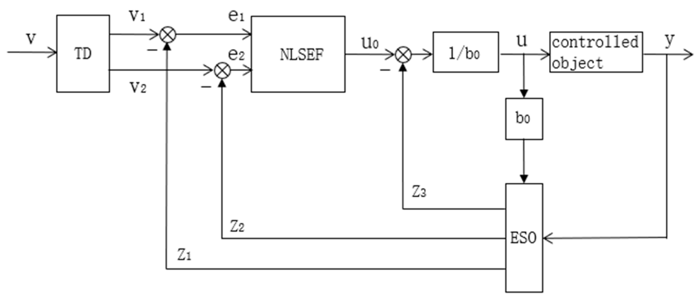
2.3.1. Active Disturbance Rejection Control

The ADRC architecture consists of three components: the Tracking Differentiator (TD), the Extended State Observer (ESO), and the Nonlinear State Error Feedback (NLSEF), as shown in Figure 2. These components work collaboratively to achieve effective disturbance suppression and precise control. The TD smooths the input signal and extracts its differential information, preventing abrupt control commands and balancing system responsiveness with stability. The ESO models the system’s internal nonlinear dynamics and external disturbances as a unified “total disturbance”, which is estimated and compensated in real time, significantly enhancing the system’s disturbance rejection capability. The NLSEF generates the control signal by nonlinearly combining the state errors, replacing the linear weighted approach of traditional PID control, thereby optimizing dynamic response and robustness.
The core strength of this architecture lies in its dynamic compensation capability: the ESO eliminates the effects of disturbances in real time, reducing the dependence on an accurate system model. Meanwhile, the synergy between TD and NLSEF effectively suppresses high-frequency oscillations and minimizes chattering. With strong adaptability, ADRC is particularly suitable for nonlinear and strongly coupled systems, such as UAV attitude control. Through a closed-loop mechanism of “observation–compensation–feedback”, it achieves high-precision and highly robust control objectives [26,27].
1.
Tracking Differentiator (TD)
The TD, also known as the transition process regulator, is designed to smooth the desired external input signal, enabling a gradual transition. This helps avoid abrupt control actions caused by a large discrepancy between the desired and actual values, thus balancing the precision and speed of the system’s response. Unlike traditional differentiators, which may face issues such as local non-differentiability, noise interference, or signal distortion during signal extraction, TD ensures a smooth transition of the input signal while effectively extracting its differential information, thereby improving control performance.
The expression for the TD is as follows:
v 1 = v 1 + h v 2 v 2 = v 2 + h f h f h = fhan v 1 v 0 , v 2 , r 0 , h 0
where the function fhan is designed to construct a nonlinear error feedback term, enabling smooth tracking and finite-time convergence, h   is the sampling step size, and the velocity factor and filter factor are denoted as r 0 and h 0 , respectively, v 1 is the smooth tracking value of the reference signal, and v 2 is the differential estimation of the reference signal.
2.
Extended State Observer (ESO)
Compared to traditional observers, ESO does not require an explicit form of disturbances to estimate them. Its principle is to unify both internal and external disturbances into a total disturbance and extend it as a new state variable. ESO estimates the total disturbance in real time by analyzing the system’s control inputs and outputs and then compensates for it. As the core component of the ADRC, ESO exhibits strong adaptability, effectively addressing complex factors, such as strong coupling, nonlinearity, model uncertainties, and external disturbances, enabling precise observation and dynamic compensation.
Typically, the ESO is constructed using a common second-order system, with the second-order system form assumed to be as follows:
x ˙ 1 = x 2 x ˙ 2 = f x 1 , x 2 + d ( t ) + b u y = x 1
The above equation is expanded to the following form:
x ˙ 1 = x 2 x ˙ 2 = x 3 + b u x ˙ 3 = f ˙ x 1 , x 2 , ω y = x 1
The expansion of the above system is simplified to the following form:
y = f x 1 , x 2 , d ( t ) + b u
where the system state variables are x 1   and x 2 , the control input is u , and the disturbance variable is d t . Expanding the above equation leads to the corresponding ESO for the system, as shown below:
e ( t ) = z 1 ( t ) x 1 ( t ) z ˙ 1 ( t ) = z 2 ( t ) β 01 e ( t ) z ˙ 2 ( t ) = z 3 ( t ) β 02 fal e ( t ) , α 1 , δ + b u ( t ) z ˙ 3 = β 03 fal e ( t ) , α 2 , δ
fal ( e , α , δ ) = | e | α sign ( e ) , | e | > δ e δ 1 α , | e | δ δ > 0
where the observed values of x 1 , x 2 , x 3 are z 1 , z 2 , and z 3 , respectively. The error between the estimated and actual values is represented by e . The observation gains β 01 , β 02 , and β 03 are all greater than 0. The filtering factor is denoted as δ , and the nonlinear function is fal , where α 1 , α 2 , and α are the nonlinear factors.
3.
Nonlinear State Error Feedback Control (NLSEF)
Traditional PID control generates control inputs by applying proportional, integral, and derivative weighting to the error. However, in high-precision control applications, the performance may not be ideal. NLSEF combines nonlinear feedback structures with state errors, adjusting the control gains based on different error intervals. This approach allows for more precise and efficient control while also enhancing the system’s robustness and adaptability.
In a second-order system, the state errors z 1 and z 2 are typically obtained by subtracting the output signals v 1 and v 2 from the observed signals, respectively. Thus, the state errors are represented as:
e 1 = v 1 z 1 e 2 = v 2 z 2
By performing a nonlinear combination of the state errors in the above equation, the NLSEF control law is obtained as follows:
u 0 = k 1 f a l e 1 , α 1 , δ + k 2 fal e 2 , α 2 , δ
where the control feedback gains are k 1 and k 2 .

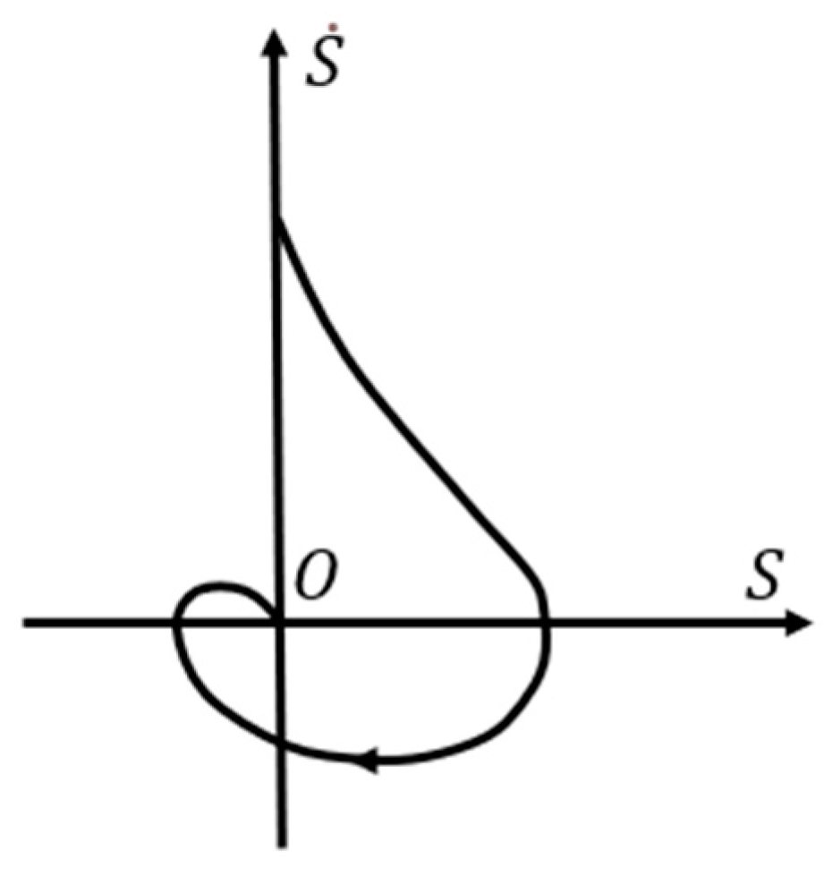
2.3.2. ST-SMC Theory

The inherent chattering phenomenon in sliding mode control remains a persistent challenge that critically constrains its real-world deployment, driving sustained academic investigation to address this fundamental limitation. Arie Levant introduced the concept of the sliding order, which is defined as the degree to which the sliding mode variable ss has continuous derivatives of zero on the sliding surface. In first-order sliding mode control, the first derivative of the sliding mode variable exhibits discontinuity, resulting in a sliding order of 1. To reduce chattering, higher-order sliding mode control hides the discontinuous terms within the higher-order derivatives of the sliding mode variable, causing the higher-order derivatives to progressively approach zero on the sliding surface. This is coupled with integral filtering to smooth the switching control, fundamentally eliminating chattering [28].
While higher-order sliding mode control effectively reduces chattering, excessively high orders may increase computational complexity and hinder theoretical analysis. Therefore, second-order sliding mode control retains the benefits of higher-order sliding mode while simplifying the controller design, making it more suitable for engineering applications. Among these, the super-twisting algorithm is a typical second-order sliding mode algorithm. It only requires information about the sliding mode variable, is computationally simple, and achieves remarkable control performance, which is why it is widely used in engineering practice.
The basic form of the super-twisting algorithm is shown below:
u a s s = k 1 | s | 1 2 sgn ( s ) + u 1 u ˙ 1 = k 2 sgn ( s )
where s is the sliding mode variable, u 1 is the intermediate variable, and k 1 and k 2 are the parameters to be designed. The sufficient conditions for finite-time stability are as follows [25]:
k 2 > d ¯ k 1 2 > 2 k 2 + d ¯
From Equation (21), it can be observed that although the super-twisting algorithm involves two discontinuous switching terms, this does not affect the overall continuity of the control system. When the system state approaches the sliding surface, i.e., s ≈ 0, the term k 1 s 1 / 2 sgn ( s ) in Equation (21) ensures that the term s 1 / 2 tends to zero. Additionally, the nonlinear switching function of the intermediate variable u 1 acts on its first derivative and is processed by integration, thus mitigating the impact of the switching function. Therefore, near the sliding surface, the sliding variable and its first derivative remain continuous, ensuring smooth operation of the system. The corresponding phase trajectory is shown in Figure 3, characterized by the sliding variable spiraling toward the equilibrium point.

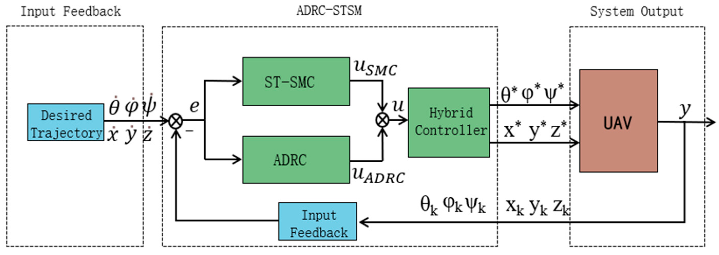
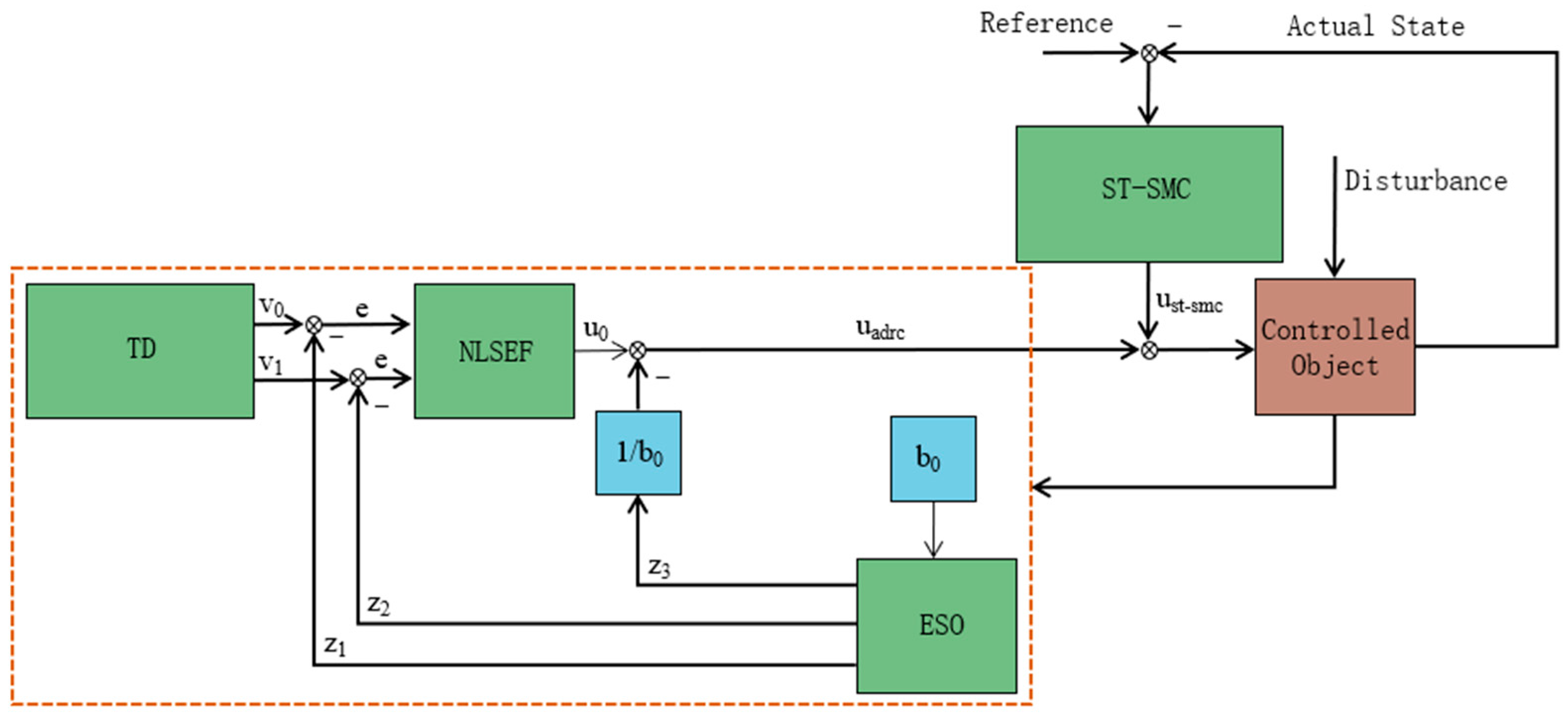
2.3.3. ADRC and ST-SMC Hybrid Control

This control algorithm effectively combines ADRC and the ST-SMC algorithm to achieve complementary performance. Under conditions of random airflow disturbances, the hybrid algorithm design allows for the dynamic compensation characteristics of ADRC to stabilize external disturbances, while the robustness of ST-SMC suppresses the effects of system nonlinearities and uncertainties on control accuracy. This method significantly enhances the UAV’s attitude stability and self-balancing performance in complex environments, ensuring excellent dynamic and static control under random disturbances while maintaining high real-time performance and control efficiency. The following Figure 4 shows the system block diagram of the algorithm implementation.
  • ADRC Design
The core of ADRC is based on ESO for disturbance compensation and control law design.
(1)
Extended State Observer (ESO)
By introducing the control input u and disturbance d(t) into the model, the dynamics can be rewritten as:
x . = f ( x ) + g ( x ) u + d ( t )
The ESO is utilized to estimate both the disturbance d(t) and the system states:
z ˙ 1 = z 2 β 1 z 1 y , z ˙ 2 = z 3 β 2 z 1 y + g · u , z ˙ 3 = β 3 z 1 y
where z 1 , z 2 , and z 3 correspond to the observed variable’s value, its first derivative, and its second derivative, respectively. y is the measured system output, and β 1 , β 2 , and β 3 are the gain coefficients of the ESO.
To ensure the convergence and stability of the ESO, the gain coefficients β 1 , β 2 , and β 3 can be determined using the pole placement method. Assuming the poles of the ESO are located at ω 1 , the gain coefficients are designed as:
β 1 = 3 ω 0 ,   β 2 = 3 ω 0 2 ,   β 3 = 3 ω 0 3
where ω 0 is the bandwidth parameter of the ESO, which determines the convergence speed of the ESO.
(2)
Control Law Design
The ADRC control law is based on the output of the ESO:
u = 1 g f ^ ( x ) + d ^ ( t ) + k s e
where f ^ ( x ) is the estimated system dynamics, d ^ t is the estimated disturbance, and k s is the error feedback gain.
To compensate for the unknown part of the system, f ( x ) + d ( t ) , the control input u ADRC is defined as:
u ADRC = f ^ ( x ) + d ^ ( t ) g ( x )
where f ^ ( x ) and d ^ ( t ) are the estimates of f(x) and d(t) by the ESO, g ( x ) is used to normalize the control input u, ensuring that the control law can accurately compensate for the nonlinear dynamics of the system. Substituting these values eliminates most of the unknown dynamics, and the remaining terms are the estimation errors f ~ = f f ^ and d ~ = d d ^ .
(3)
Error Feedback Gain Design
The error feedback gain can be designed using Equation (28):
k e   = 2 ζ ω n  
where ζ is the damping ratio, and ω n is the natural frequency. By adjusting ζ and ω n , the dynamic response characteristics of the system can be controlled.
  • ST-SMC Design
Although sliding mode control, as a new nonlinear control method proposed by modern control theory, not only possesses strong robustness but also features high dynamic performance, its design approach involves creating a sliding surface to drive the system states toward the designed surface, thereby achieving high-precision dynamic tracking of complex nonlinear systems. However, in practical applications, traditional sliding mode control exhibits high-frequency chattering during the switching between sliding surfaces, which limits the controller’s effectiveness. To address this issue, a new higher-order sliding mode control method based on sliding mode control has been developed. This method not only incorporates the many advantages of sliding mode control but also suppresses the high-frequency chattering caused by switching control. This method is known as ST-SMC. The core idea of this method is to optimize the higher-order sliding mode algorithm by designing a suitable sliding surface that satisfies the Lyapunov stability conditions. By integrating smoothing function approximations, filters, and other optimization algorithms, the dynamic response of the control signal is further smoothed. This approach effectively enhances the steady-state accuracy and stability performance of the controller.
Therefore, for the design of an ST-SMC controller, the design of the sliding surface is crucial. The following will provide a detailed analysis of the basic principles and methods for designing the sliding surface.
(1)
Sliding Surface Design
The sliding surface is defined as:
S = e ˙ + λ e
where e = x x r e f represents the tracking error, and λ is the sliding surface gain.
(2)
ST-SMC Law
The super-twisting control incorporates higher-order terms to reduce chattering:
u ST SMC = 1 g ( x ) k 1 | S | 1 / 2 sign ( S ) k 2 S
where k 1 and k 2 are the sliding mode gains. To ensure the stability of the ST-SMC, the sliding mode gains must satisfy the following conditions:
k 1 > 2 ε α , k 2 > ε α 2
Here, ε is the upper bound of the system’s uncertainty, and α is a positive number, typically set to 1. These conditions ensure the robustness and stability of the sliding mode control.
To further suppress the chattering phenomenon in sliding mode control, a saturation function is incorporated into the control law, resulting in the control system as follows:
u ST SMC = 1 g ( x ) k 1 | S | 1 / 2 s a t ( S ) k 2 S
where s a t ( S ) is the saturation function, defined as:
s a t ( S ) = s i g n ( S )         i f   | S | > δ S     δ i f   | S | > δ
Here, δ in the saturation function is a positive number used to control the smoothness of the saturation function.
  • Design of ADRC and ST-SMC Hybrid Control
The Extended State Observer (ESO) from ADRC is used to observe the system states and disturbances in real time. The state equation is:
z ˙ 1 = z 2 β 1 z 1 y
z ˙ 2 = z 3 β 2 z 1 y + g u
z ˙ 3 = β 3 z 1 y
where z 1 , z 2 , and z 3 correspond to the observed variable’s value, its first derivative, and its second derivative, respectively. y is the measured system output, and β 1 , β 2 , and β 3 are the gain coefficients of the ESO.
Using the state observer in ADRC, the system states and disturbances can be estimated as:
u ADRC = f ^ ( x ) + d ^ ( t ) g ( x )
By employing disturbance compensation, the effects of system dynamics and external disturbances can be eliminated.
Introducing the disturbance from the state observer into the control law for compensation, the disturbance compensation term in ADRC is:
d ^ ( t ) = z 3 , f ^ ( x ) = z 2
By incorporating a saturation function into the original control law, the chattering phenomenon in sliding mode control is suppressed. The control law is as follows:
u ST - SMC = 1 g ( x ) k 1 | S | 1 / 2 s a t ( S ) k 2 S
The final control input u in this chapter’s algorithm is composed of the disturbance compensation term from ADRC and the ST-SMC:
u = u ADRC + u ST - SMC
Substituting u ADRC and u ST - SMC into Equation (41), we obtain:
u = f ^ ( x ) + d ^ ( t ) g ( x ) + 1 g ( x ) k 1 | S | 1 / 2 s a t ( S ) k 2 S
After simplification, the final control input is obtained:
u = 1 g ( x ) f ^ ( x ) + d ^ ( t ) k 1 | S | 1 / 2 s a t ( S ) k 2 S
Here, we derive the dynamics of the super-twisting sliding mode surface. From the above definition of the sliding surface S, the sliding surface can be expressed as:
S = e ˙ + λ e
The sliding surface dynamics S ˙ can be expressed as:
S ˙ = x ˙ r x ˙ = x ˙ r [ f ( x ) + g ( x ) u + d ( t ) ]
Substituting the final control input u into the equation, we obtain:
S ˙ = x ˙ r f ( x ) g ( x ) f ^ ( x ) + d ^ ( t ) g ( x ) + 1 g ( x ) k 1 | S | 1 / 2 s a t ( S ) k 2 S d ( t )
After simplification, we obtain:
S ˙ = x ˙ r f ^ ( x ) d ^ ( t ) + f ˜ + d ˜ + k 1 | S | 1 / 2 s a t ( S ) + k 2 S
Assuming the trajectory tracking error is zero, we have:
x ˙ r f ^ ( x ) d ^ ( t ) = 0
It can be further simplified as:
S ˙ = f ˜ + d ˜ k 1 | S | 1 / 2 s a t ( S ) k 2 S
Through the derivation of the ADRC and the ST-SMC for the quadrotor UAV under wind disturbance conditions, the overall control law of the system was ultimately obtained. In the controller, the disturbance term and the Super-Twisting-Sliding Mode Control (ST-SMC) term play pivotal roles, working synergistically to enhance the overall system performance. In this hybrid control approach, the disturbance term is primarily generated by the Extended State Observer (ESO) within Active Disturbance Rejection Control (ADRC), whose core function is to estimate and compensate for unknown system dynamics and external disturbances (such as random airflow) in real time. By incorporating the estimated disturbance d ^ t and system dynamics f ^ ( x ) into the control law, the impact of model uncertainties on the system is significantly reduced. On the other hand, the super-twisting sliding mode control term further strengthens system robustness on the basis of disturbance compensation by designing an appropriate sliding surface S and implementing a higher-order control law. The inclusion of the sliding mode term enforces the system states to converge along the sliding surface, and even in the presence of residual estimation errors f ~ and d ~ , its strong nonlinear characteristics ensure rapid response and system stability. Moreover, the use of a saturation function in the super-twisting control smooths the control signal, effectively suppressing the high-frequency chattering typically associated with conventional sliding mode control.
Furthermore, the dynamic sliding surface was derived, which helped to clarify the entire control process of the controller. The control algorithm block diagram is shown below in Figure 5.
  • Lyapunov stability proof
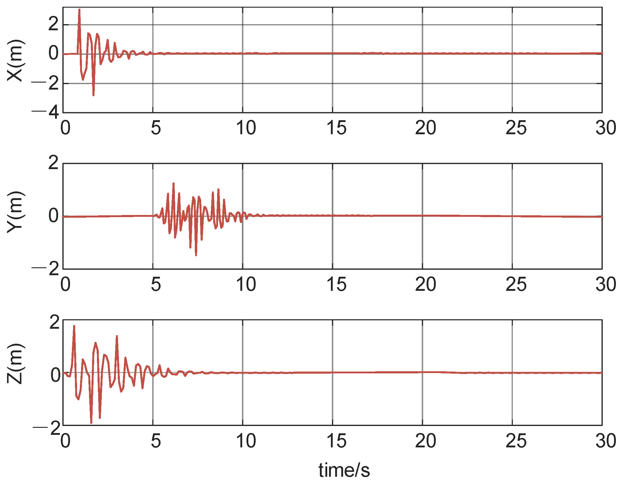
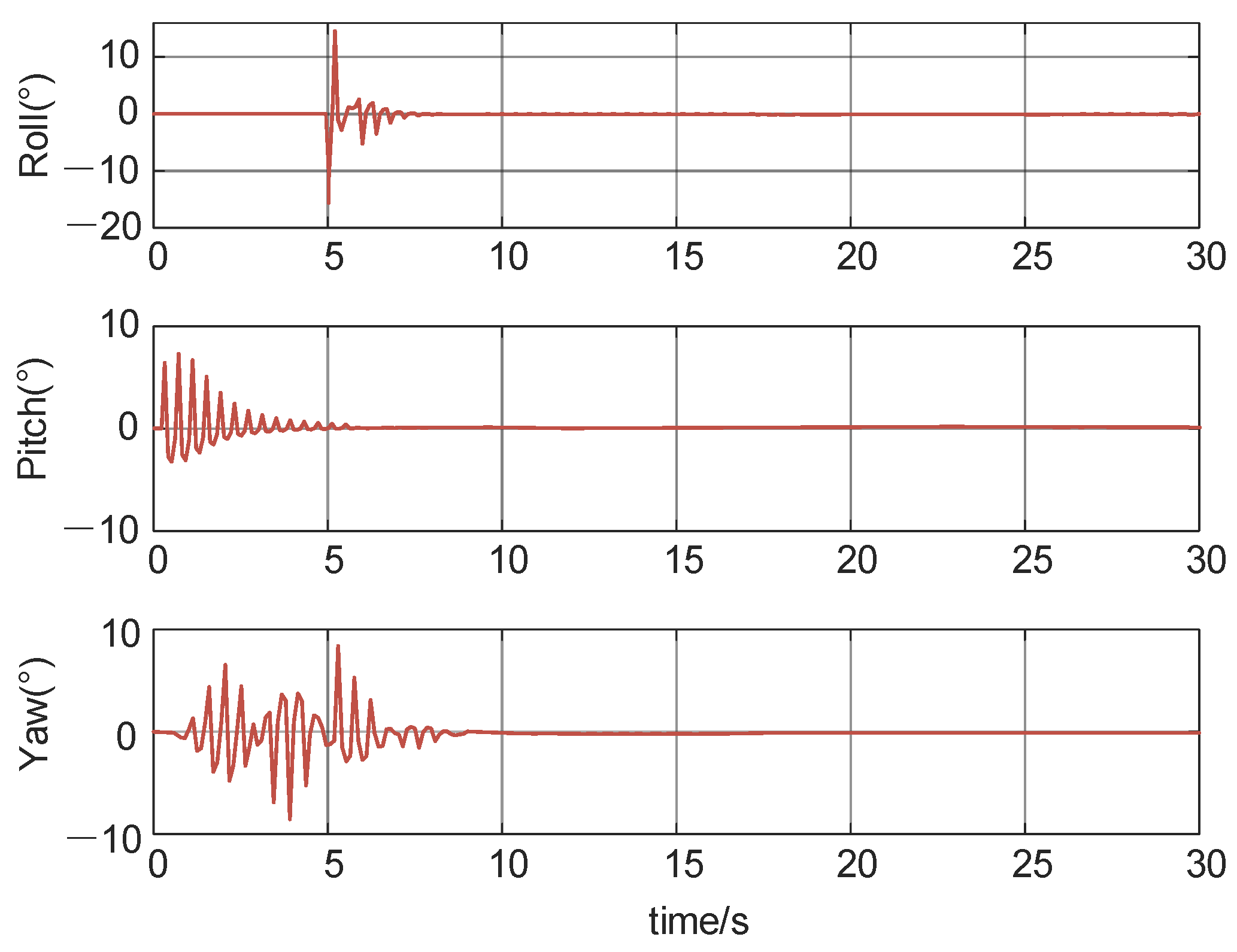
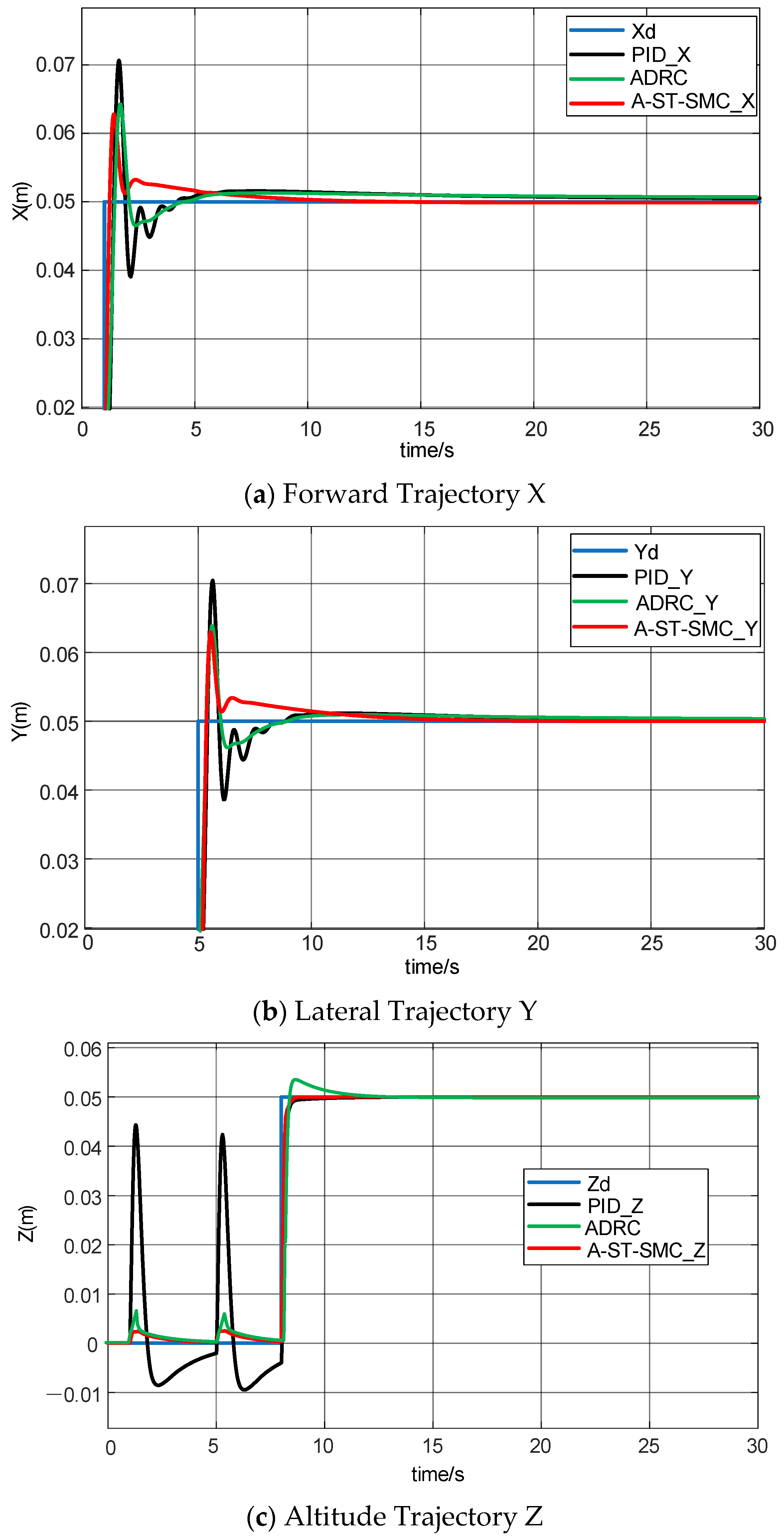
Define the Lyapunov function as:
V ( S ) = 1 2 S 2
The derivative is:
V ˙ ( S ) = S S ˙ = S f ˜ + d ˜ k 1 | S | 1 / 2 sat ( S ) k 2 S
Decompose V ˙ ( S ) into disturbance terms and sliding mode control terms for individual discussion. First, consider the contribution of the disturbance terms. Since | f ˜ | ϵ f and | d ˜ | ϵ d are bounded, we have:
S ( f ˜ + d ˜ ) | S | ϵ f + ϵ d
Next, consider the contribution of the super-twisting sliding mode term. The two components of the super-twisting sliding mode control are k 1 | S | 1 / 2 sat ( S )   and k 2 S :
For k 1 | S | 1 / 2 sat ( S )   , we have:
S k 1 | S | 1 / 2 s a t ( S ) = k 1 | S | 1 / 2 S s a t ( S )
Since s a t ( S ) is | S | > δ when sign ( S ) , and | S | δ when S δ , we have:
S s a t ( S ) = | S |   if   | S | > δ S 2 δ   if   | S | δ
S k 1 | S | 1 / 2 s a t ( S ) = k 1 | S | 3 / 2   if   | S | > δ k 1 | S | 1 / 2 S 2 δ   if   | S | δ
For k 2 S , we have:
S k 2 S = k 2 S 2
By combining the disturbance terms and the sliding mode control terms, we obtain:
V ˙ ( S ) | S | ϵ f + ϵ d k 1 | S | 1 / 2 S s a t ( S ) k 2 S 2
According to the different cases of s a t ( S ) , we can discuss the following two situations:
Case 1: When | S | > δ , at this time, s a t ( S ) = sign ( S ) ; therefore:
V ˙ ( S ) | S | ϵ f + ϵ d k 1 | S | 3 / 2 k 2 S 2
To ensure V ˙ ( S ) 0   , it is necessary to satisfy:
k 1 | S | 1 / 2 + k 2 | S | ϵ f + ϵ d | S |
Case 2: When | S | δ , at this time, s a t ( S ) = S δ ; therefore:
V ˙ ( S ) | S | ϵ f + ϵ d k 1 | S | 1 / 2 S 2 δ k 2 S 2
To ensure V ˙ ( S ) 0   , it is necessary to satisfy:
k 1 | S | 1 / 2 S 2 δ + k 2 S 2 | S | ϵ f + ϵ d
Finally, to ensure the asymptotic stability of the system in the Lyapunov sense, the sliding mode gains must satisfy the following conditions:
1. When | S | > δ , we have:
k 1 > max | S | ϵ f + ϵ d | S | 1 / 2 , k 2 > max | S | ϵ f + ϵ d | S |
2. When | S | δ , we have:
k 1 > max | S | ϵ f + ϵ d | S | 1 / 2 δ S 2 , k 2 > max | S | ϵ f + ϵ d S 2
Therefore, when k1 and k2 satisfy the above conditions, the system is asymptotically stable in the Lyapunov sense.

3. Results

To verify the performance of the ADRC-ST-SMC (A-ST-SMC) algorithm proposed in this paper, it is applied to the attitude and position control system of a quadrotor UAV and evaluated through simulations using MATLAB 2024b. The simulation parameters are shown in Table 2 below.
The control simulations are primarily carried out under random airflow disturbance conditions. The tracking ability of the control algorithm in the position direction is assessed by observing the UAV’s position tracking and position error analysis. Additionally, the dynamic response performance and robustness of the control algorithm are validated by observing the UAV’s attitude stability and attitude angle errors.
Figure 6 and Figure 7 below show the use of the Dryden turbulence model to simulate random airflow disturbances, which serves as the disturbance model for validating the proposed algorithm.
The curve shown in Figure 8a represents the output curves of three control methods for the UAV. From the analysis of the curve, it can be concluded that at the beginning, the system experiences significant fluctuations due to the impact of disturbed airflow. Random airflow disturbance is introduced between 0 and 5 s. By observing the PID and ADRC control curves, it can be seen that these two control algorithms exhibit significant overshoot and oscillation in their output curves, indicating insufficient stability of the UAV’s control under random airflow disturbances. However, by observing the A-ST-SMC, it is evident that the amplitude of its overshoot is significantly lower than that of the traditional PID and ADRC algorithms. Moreover, the oscillation frequency and magnitude of the curve are superior to those of PID and ADRC algorithms, reflecting that the A-ST-SMC control algorithm exhibits stronger robustness against random airflow disturbances, with the curve quickly returning to stability. After the final 5 s, all three control algorithms gradually stabilize. However, through comparison, it can be observed that the time for stabilization in A-ST-SMC is shorter than that in PID and ADRC. It can also be concluded that the performance of PID and ADRC under random airflow disturbance is inferior to that of A-ST-SMC. Figure 8b shows the same curves as Figure 8a.
Figure 8c shows the altitude trajectory response curve of the UAV. It can be observed that in the initial stage, from 0 to 5 s, after random airflow disturbance is introduced, the traditional control algorithms exhibit significant jitter and tracking errors with large jitter amplitudes. In comparison, the performance of the A-ST-SMC algorithm is clearly superior to PID and ADRC. From the figure, it is evident that both the jitter amplitude and the convergence speed of A-ST-SMC are much lower than those of PID and ADRC. After the UAV has completely stabilized, it is found that PID and ADRC always have errors with the reference value, while the output of A-ST-SMC completely coincides with the reference value.
By observing the trajectory tracking position simulation results of the UAV in Figure 6, it can be concluded that the A-ST-SMC algorithm outperforms traditional PID and ADRC control algorithms in terms of dynamic response, disturbance rejection performance, and steady-state tracking error. This also indicates that the proposed control algorithm consistently demonstrates high-precision tracking in the position direction under random airflow disturbance conditions.
The curve shown in Figure 9a demonstrates the dynamic response of the UAV in the roll angle direction under random airflow disturbance conditions. For convenience of analysis, the UAV’s dynamic response is divided into two stages: the initial stage from 0 to 5 s and the steady-state stage after 5 s. In the initial stage, when the random airflow disturbance is introduced, the PID and ADRC control algorithm curves show significant fluctuations, and after being disturbed by random airflow, there is a notable deviation that takes a long time to recover stability. In contrast, the A-ST-SMC shows better disturbance rejection performance. From the curve, it can be observed that with the introduction of random airflow, the A-ST-SMC curve hardly exhibits overshoot or long-lasting jitter, and during the steady-state phase, the curve quickly converges to zero.
Figure 9b shows the dynamic response curve of the UAV in the pitch angle direction. From the curve, it can be observed that in the initial stage, due to the random airflow disturbance, PID, ADRC, and A-ST-SMC all exhibit significant fluctuations. However, upon examining the curve, it is apparent that the fluctuations in the PID and ADRC control algorithms, both in terms of amplitude and duration, are significantly larger than those of the A-ST-SMC control algorithm. Especially after the random airflow disturbance disappears, the output curve of A-ST-SMC always recovers to a stable state, while PID and ADRC take relatively longer to converge.
Similarly, Figure 9c shows the dynamic response curve of the UAV in the yaw angle direction. In the initial stage, from 0 to 5 s, due to the random airflow disturbance introduced into the system, the PID, ADRC, and A-ST-SMC curves all show considerable jitter and prolonged fluctuations. Particularly, PID and ADRC show more frequent and larger fluctuations than A-ST-SMC. In the steady-state phase, A-ST-SMC can quickly recover to a stable state after the random airflow disturbance disappears, while PID and ADRC require a relatively longer time to stabilize. From the comparison, it can be seen that PID and ADRC, whether in terms of overshoot magnitude, fluctuation frequency, or the time required to recover to a steady state, are significantly worse than A-ST-SMC. This also indicates that the A-ST-SMC demonstrates greater robustness and superiority under random airflow disturbance conditions.
From the analysis of the above curves, it can be concluded that the A-ST-SMC algorithm significantly outperforms traditional PID and ADRC control algorithms in terms of dynamic response, disturbance rejection performance, and steady-state control accuracy in the roll, pitch, and yaw directions. It also demonstrates that this algorithm can achieve faster convergence speeds and higher precision when dealing with complex disturbances, showing faster response times and better stability. Furthermore, it has significant advantages in disturbance rejection ability and precise steady-state performance, fully proving the applicability and superiority of this algorithm in complex environments such as airflow disturbances.
The curves shown in Figure 10a–c represent the position tracking error curves of the UAV on the X, Y, and Z axes, respectively, in order to verify the self-balancing control of the UAV under random airflow disturbance conditions using the control algorithm proposed in this paper. Random airflow disturbance is introduced between 0 and 5 s, and the output curves of the traditional control algorithms, PID, ADRC, and A-ST-SMC algorithm, are observed to analyze the response performance of the three algorithms to random airflow disturbances.
By observing the curves, it can be seen that in the disturbance phase, the error in the output curves of the traditional control algorithms shows a more significant jitter. Although the magnitude of the jitter is relatively small, the time for the magnitude to decrease is quite long. In contrast to the traditional control algorithms, the output curves of the algorithm proposed in this paper show a more impressive performance. By observing the curves, it is evident that A-ST-SMC quickly recovers to a steady state, and its jitter magnitude is lower than that of ADRC and PID.
From the analysis of the UAV position tracking error curves, the following conclusions can be drawn: The A-ST-SMC algorithm significantly outperforms traditional control algorithms in terms of error tracking on the X, Y, and Z axes, as well as the fast convergence during the stable phase after the disturbance. This further reflects the disturbance rejection performance of the algorithm under random airflow disturbances.
Figure 11a–c show the error-tracking curves of the UAV’s attitude angles in the roll, pitch, and yaw directions, respectively. Similarly, random airflow disturbance is introduced between 0 and 5 s, and the steady-state performance of the three algorithms in terms of attitude angle direction is observed.
By observing the roll angle error curve in Figure 11a, it can be seen that traditional control algorithms always exhibit large overshoot disturbances during the disturbance phase, and the curves show long jitter times. However, although A-ST-SMC exhibits an overshoot momentarily, the controller adjusts to reduce the overshoot each time it occurs during subsequent oscillations, and the jitter magnitude is clearly lower than that of the PID and ADRC control algorithms.
Similarly, by observing the yaw angle error curve in Figure 11c, it can be seen that both PID and ADRC not only show large overshoots but also experience significantly more oscillations. However, A-ST-SMC performs better in terms of both error peak values and convergence speed compared to the traditional control algorithms.
From the above analysis, it can be concluded that in the UAV’s attitude angle error tracking curves, the A-ST-SMC algorithm significantly outperforms traditional control algorithms in terms of robustness, error tracking ability, and response speed. This further proves the tracking performance and adaptability of the algorithm under airflow disturbances.
Figure 12 shows the experimental results of the UAV’s attitude angular velocity. From the curves in the figure, it can be observed that after encountering airflow, the UAV adjusts its attitude angular velocity to bring the UAV body to a balanced state. By comparing the traditional PID algorithm, ADRC algorithm, and the A-ST-SMC, it can be seen that under the adjustment of the fusion controller, the UAV quickly stabilizes its attitude. However, both PID and ADRC algorithms exhibit much larger overshoots and slower response speeds than the fusion controller.
Table 3 compares the traditional PID algorithm, the ADRC algorithm, and the control method proposed in this study. The results indicate that the control algorithm presented in this paper offers significant advantages over traditional methods in terms of response amplitude and reaction time. This improvement is mainly attributed to the design of the integrated controller. However, this strategy also introduces a considerable computational burden, increasing the overall complexity of the algorithm. Nevertheless, the performance gains suggest that the added complexity is justified. Future research will focus on optimizing the computational efficiency of the algorithm, aiming to reduce the processing load and simplify the control structure, making it a more practical and efficient control solution.

4. Discussion

The experimental simulations validate the advantages of the hybrid algorithm. During the dynamic response phase, the algorithm exhibits significant disturbance rejection capability and fast convergence, particularly under the influence of airflow disturbances, where the UAV quickly returns to the desired trajectory. In the steady-state phase, the steady-state error of the algorithm’s output is almost zero, demonstrating excellent tracking performance. Compared to traditional PID control, the hybrid algorithm shows significant advantages in response speed, disturbance rejection capability, and control precision, providing reliable technical support for stable UAV operation in complex dynamic environments.

5. Conclusions

This study addresses the technical challenge of achieving stable control for Unmanned Aerial Vehicles (UAVs) operating in complex nonlinear systems and under random airflow disturbances by proposing a hybrid control algorithm that integrates Active Disturbance Rejection Control (ADRC) with Super Twisting-Sliding Mode Control (ST-SMC). By leveraging the advantages of ADRC in disturbance estimation and compensation and the strengths of ST-SMC in enhancing system robustness and suppressing high-frequency chattering, the proposed approach achieves complementary improvements in control performance. The hybrid algorithm effectively mitigates external disturbances, reduces system oscillations, and significantly enhances the accuracy and stability of attitude and trajectory control.
Simulation results demonstrate that the proposed algorithm exhibits strong disturbance rejection and fast convergence during the dynamic response phase. Even under severe airflow disturbances, the UAV quickly returns to the desired trajectory. In the steady-state phase, the output error approaches zero, indicating excellent control precision and tracking performance. Compared with traditional PID control and single control strategies such as ADRC, the hybrid algorithm shows clear advantages in terms of response speed, robustness, and control accuracy.
This research not only enriches the theoretical framework of UAV attitude control but also provides a reliable solution for stable UAV operation under complex weather and disturbance conditions. In the future, this algorithm can be extended to various types of unmanned systems and more complex three-dimensional flight environments, laying a foundation for the advancement of intelligent flight control technologies and the realization of highly reliable autonomous flight missions.

Author Contributions

Conceptualization, Y.G. and B.W.; software, Y.G.; formal analysis, Y.G.; investigation, Z.L., J.G. and J.Z.; resources, B.W.; data curation, N.H.; writing—original draft preparation, Y.G. and J.Z.; writing—review and editing, Y.G., N.H., and B.W.; visualization, Y.G.; supervision, B.W.; project administration, X.H.; funding acquisition, B.W. All authors have read and agreed to the published version of the manuscript.

Funding

This research was supported by the Shenyang Science and Technology Plan Project (No.23-407-3-33).

Institutional Review Board Statement

Not applicable.

Informed Consent Statement

Not applicable.

Data Availability Statement

The original contributions presented in this study are included in the article. Further inquiries can be directed to the corresponding author.

Conflicts of Interest

The authors declare no conflict of interest.

References

  1. Zhang, Q. Research on UAV control based on intelligent fuzzy PID control. In Proceedings of the 2024 IEEE 4th International Conference on Power, Electronics and Computer Applications (ICPECA), Shenyang, China, 26–28 January 2024; pp. 1053–1056. [Google Scholar] [CrossRef]
  2. Song, W.; Li, Z.; Xu, B.; Wang, S.; Meng, X. Research on improved control algorithm of quadrotor UAV based on fuzzy PID. In Proceedings of the 2022 IEEE International Conference on Artificial Intelligence and Computer Applications (ICAICA), Dalian, China, 24–26 June 2022; pp. 361–365. [Google Scholar] [CrossRef]
  3. Ziquan, Y.; Youmin, Z.; Bin, J. PID-type fault-tolerant prescribed performance control of fixed-wing UAV. J. Syst. Eng. Electron. 2021, 32, 1053–1061. [Google Scholar] [CrossRef]
  4. Zhang, H.; Yang, L. Position and attitude control based on single neuron PID with gravity compensation for quadrotor UAV. J. Aerosp. Technol. Manag. 2023, 15, e1023. [Google Scholar] [CrossRef]
  5. Yuan, M.; Wang, C.; Zhang, P.; Wei, C. PID with deep reinforcement learning and heuristic rules for autonomous UAV landing. In Proceedings of the International Conference on Autonomous Unmanned Systems, Xi’an, China, 23–25 September 2022; Springer: Singapore, 2022. [Google Scholar] [CrossRef]
  6. Takaoğlu, F.; Alshahrani, A.; Ajlouni, N.; Ajlouni, F.; Al Kasasbah, B.; Özyavaş, A. Robust nonlinear non-referenced inertial frame multi-stage PID controller for symmetrical structured UAV. Symmetry 2022, 14, 689. [Google Scholar] [CrossRef]
  7. Huang, J.; Ma, X.; Wang, B.; Zhang, Y.; Xin, G.; Zhang, Y. Trajectory tracking control of a quadrotor UAV by cascaded inner-outer-loop backstepping sliding mode control. In Proceedings of the 2022 34th Chinese Control and Decision Conference (CCDC), Hefei, China, 15–17 August 2022; pp. 4725–4730. [Google Scholar] [CrossRef]
  8. Shi, X.; Hu, B.; Yin, C.; Cheng, Y.; Huang, X. Design of trajectory tracking controller with fractional-order backstepping sliding mode method for quadrotor UAV. In Proceedings of the 2018 Chinese Control and Decision Conference (CCDC), Shenyang, China, 9–11 June 2018; pp. 5960–5965. [Google Scholar] [CrossRef]
  9. Li, Y.; Tong, J. 3D multi-UAV coupled formation control based on backstepping control method. In Proceedings of the 2024 IEEE 6th Advanced Information Management, Communicates, Electronic and Automation Control Conference (IMCEC), Chongqing, China, 24–26 May 2024; pp. 1517–1521. [Google Scholar] [CrossRef]
  10. Gai, W.; Liu, X.; Zhang, J.; Zhang, G. Multi-UAVs formation fault-tolerant control based on the adaptive backstepping approach. In Proceedings of the 2023 2nd Conference on Fully Actuated System Theory and Applications (CFASTA), Qingdao, China, 14–16 July 2023; pp. 514–519. [Google Scholar] [CrossRef]
  11. Xu, H.; Zhou, Y.; Jiang, G.; Yang, H.; Han, S.; Li, X. Finite-time backstepping control for quadrotor UAV with uncertain disturbances. In Proceedings of the 2023 35th Chinese Control and Decision Conference (CCDC), Yichang, China, 20–22 May 2023. [Google Scholar] [CrossRef]
  12. Kang, H.H.; Kim, K.S.; Lee, S.S.; Ahn, C.K. Finite window neural network based sliding mode control for a UAV system. In Proceedings of the 2024 IEEE International Conference on Big Data and Smart Computing (BigComp), Bangkok, Thailand, 18–21 February 2024. [Google Scholar] [CrossRef]
  13. Wang, Q.; Wang, W.; Suzuki, S.; Namiki, A.; Liu, H.; Li, Z. Design and implementation of UAV velocity controller based on reference model sliding mode control. Drones 2023, 7, 130. [Google Scholar] [CrossRef]
  14. Pang, Q.W.; Wang, D.S.; Wu, W.; Chen, Y.; Zhu, Y.Y. Improved BP network based sliding model tracking control for a quadrotor UAV. J. Control Eng. Appl. Inform. 2022, 24, 69–79. [Google Scholar]
  15. Wang, Y.; Yu, H. Four-Rotor PID Control System Based on Particle Swarm Optimization. Small Spec. Electr. Mach. 2019, 47, 80–82. [Google Scholar]
  16. Chen, J. Research on Autonomous Flight of Quadrotor Based on Double-loop PID. Mechatronics 2018, 24, 22–27+48. [Google Scholar]
  17. Li, J.; Wang, N.; Song, X.; Hua, Y. Model Reference Adaptive-Based Backstepping Control for Quadrotor. J. Qingdao Univ. (Eng. Technol. Ed.) 2020, 35, 9–16. [Google Scholar]
  18. Lian, S.; Zhu, Y.; Meng, W.; Shao, K.; Li, H. Adaptive Fault-Tolerant Control for Quadrotor Based on the Second-Order Fast Nonsingular Terminal Sliding Mode Control. IEEE Trans. Ind. Electron. 2025, 1–11. [Google Scholar] [CrossRef]
  19. Jiang, Y.; Wang, D.; Bai, T.; Zhang, Y. Design of UAV Safety Controller Based on Predictive Error Method. Electron. Opt. Control 2025, 32, 90–94. [Google Scholar]
  20. Urbina-Brito, N.; Guerrero-Sánchez, M.-E.; Valencia-Palomo, G.; Hernández-González, O.; López-Estrada, F.-R.; Hoyo-Montaño, J.A. A predictive control strategy for aerial payload transportation with an unmanned aerial vehicle. Mathematics 2021, 9, 1822. [Google Scholar] [CrossRef]
  21. Guerrero-Sánchez, M.-E.; Hernández-González, O.; Lozano, R.; García-Beltrán, C.-D.; Valencia-Palomo, G.; López-Estrada, F.-R. Energy-based control and LMI-based control for a quadrotor transporting a payload. Mathematics 2019, 7, 1090. [Google Scholar] [CrossRef]
  22. Gui, Y.; Zheng, B.; Gao, P. Sliding mode attitude control of quadrotor UAV based on NESO-LFDC. Syst. Eng. Electron. 2024, 46, 1075–1083. [Google Scholar]
  23. Xiang, Z.; Mao, J. Modeling and Simulation of Rotor Aerodynamics for Four-Rotor UAV. Comput. Simul. 2021, 38, 48–52. [Google Scholar] [CrossRef]
  24. Tahir, Z.; Tahir, W.; Liaqat, S.A. State space system modelling of a quad copter UAV. arXiv 2019, arXiv:1908.07401. [Google Scholar]
  25. Ruderman, M.; Pisano, A.; Usai, E. Energy-saving sub-optimal sliding mode control with bounded actuation. arXiv 2023, arXiv:2305.07891. [Google Scholar]
  26. Gao, Z. On the foundation of active disturbance rejection control. Control Theory Appl. 2013, 30, 1498–1510. [Google Scholar] [CrossRef]
  27. Li, Y.; Chen, Z.; Liu, Z. Attitude control of a quad-rotor robot based on ADRC. J. Harbin Inst. Technol. 2014, 46, 115–118+123. [Google Scholar] [CrossRef]
  28. Zhou, M.; Qian, W.; Ren, K. Study of the Guidance Law for Super-Twisting Sliding-Mode Guided Projectiles with Multiple Constraints. Acta Armamentarii 2023, 44, 799–805. [Google Scholar] [CrossRef]
Figure 1. Quadrotor UAV SolidWorks structure diagram.
Applsci 15 05124 g001
Figure 2. Schematic diagram of ADRC.
Applsci 15 05124 g002
Figure 3. The phase trajectory of the super-twisting algorithm.
Applsci 15 05124 g003
Figure 4. Block diagram of the algorithm implementation system.
Applsci 15 05124 g004
Figure 5. Control algorithm block diagram.
Applsci 15 05124 g005
Figure 6. Position wind disturbance.
Applsci 15 05124 g006
Figure 7. Attitude wind disturbance.
Applsci 15 05124 g007
Figure 8. Experimental results of UAV trajectory tracking position.
Applsci 15 05124 g008
Figure 9. Experimental results of UAV attitude angles.
Applsci 15 05124 g009
Figure 10. Experimental results of UAV position tracking errors.
Applsci 15 05124 g010
Figure 11. Experimental results of UAV attitude errors.
Applsci 15 05124 g011
Figure 12. UAV attitude angular velocity experimental results.
Applsci 15 05124 g012
Table 1. QUAD X-shaped quadrotor UAV motion control principles.
Motion FormMotor 1Motor 2Motor 3Motor 4
Vertical Motion++++
Pitch (Forward/Backward)++
Roll (Lateral Motion)++
Yaw Motion++
Table 2. UAV body parameters.
ParameterDescriptionValue
mUAV mass0.698 kg
lArm length0.171 m
GGravitational acceleration9.8 m/s2
IxMoment of inertia around X-axis 0.0034   K g m 2
IyMoment of inertia around Y-axis 0.0060   K g m 2
IzMoment of inertia around Z-axis 1.302 × 1 0 6   K g m 2
β 1 Gain coefficients30
β 2 Gain coefficients300
β 3 Gain coefficients1000
k 1 Sliding mode gains20
kpProportional term in PID control2
kdDerivative term in PID control5
Table 3. The experimental results comparison and analysis.
PIDADRCST-SMC
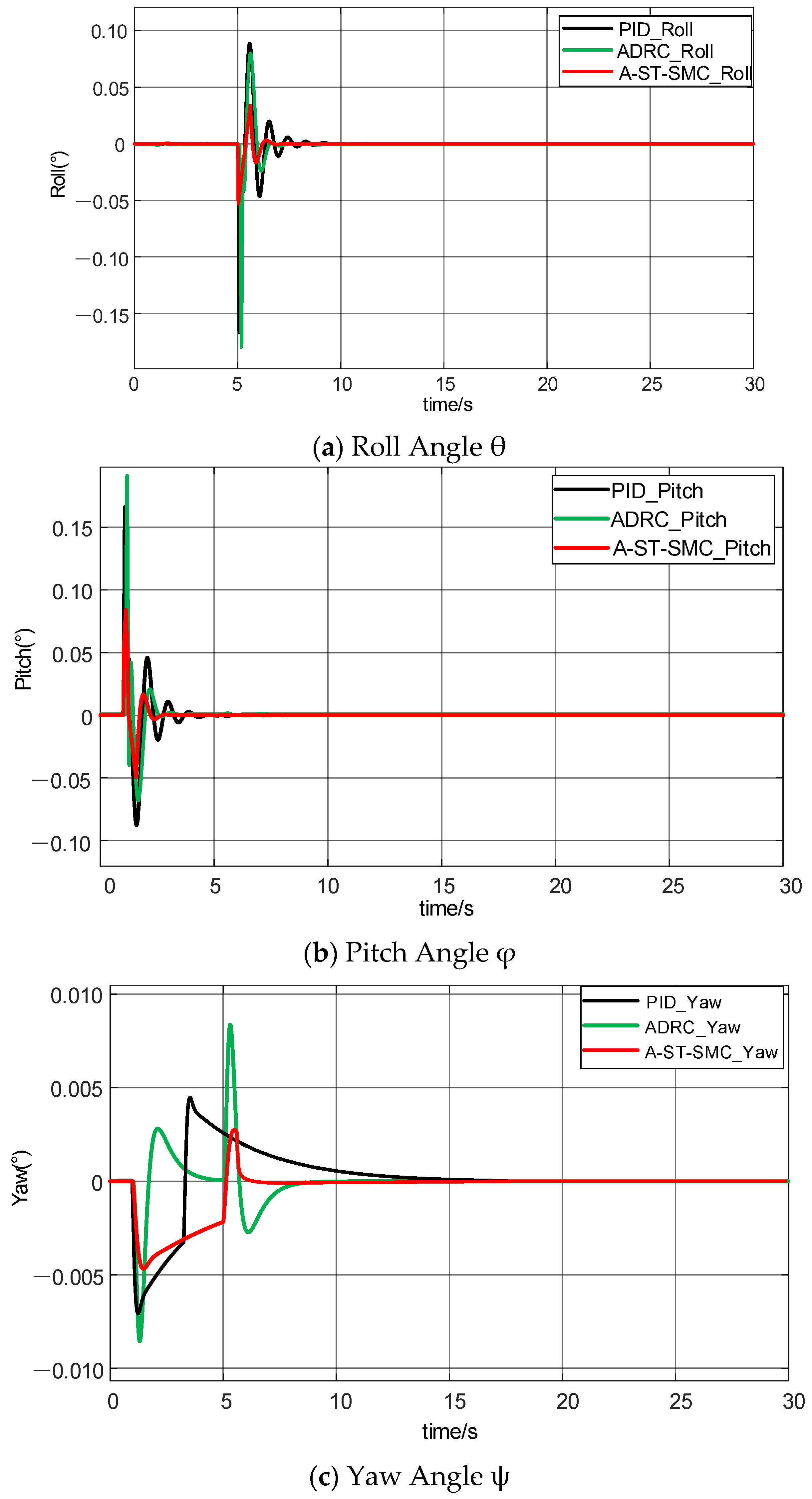
The maximum amplitude of the pitch angle (in radians)0.0160.0190.008
Time required for the pitch angle channel to stabilize (in seconds)5.5163.6872.763
The maximum amplitude of the roll angle (in radians)0.0880.0830.034
Time required for the roll angle channel to stabilize (in seconds)9.6317.2196.764
The maximum amplitude of the yaw angle (in radians)−0.007120.00834−0.00467
Time required for the yaw angle channel to stabilize (in seconds)17.2678.8736.326
Disclaimer/Publisher’s Note: The statements, opinions and data contained in all publications are solely those of the individual author(s) and contributor(s) and not of MDPI and/or the editor(s). MDPI and/or the editor(s) disclaim responsibility for any injury to people or property resulting from any ideas, methods, instructions or products referred to in the content.

