Assessment of Photogrammetric Performance Test on Large Areas by Using a Rolling Shutter Camera Equipped in a Multi-Rotor UAV
Abstract
1. Introduction
- Flight planning parameters, including: (1) flight height: this determines the spatial resolution of the registered images and the number of images per unit area [28]; the greater the height, the lower the spatial resolution, but the larger the area that can be covered. When detailed models are required, low flight heights are recommended [29]; (2) speed: high speed may capture blurry images and affect the UAV’s stability and manoeuvrability; (3) Ground Sample distance (GSD): this indicates the size represented by a pixel on the terrain [30] and is directly related to height, as the GSD is higher at greater heights, leading to lower spatial resolution; and (4) overlap: this is the partial superposition between two photographs in a frontal and lateral way. Increasing the percentage of overlapping provides better accuracy and optimises the object’s shape. Photogrammetric software, such as PIX4D [31] and Agisoft Metashape [32], suggests that images be acquired with a forward overlap > 75% and lateral overlap equal to 60%. However, when an overlap of 90% is exceeded, the stereoscopic vision is lost in the photogrammetric reconstruction [28], increasing the processing time.
- Georeferencing involves aligning spatial data or images with a specific geographic location using a coordinate reference system. This can be achieved through two main methods: direct and indirect georeferencing.Direct georeferencing is performed using a UAV equipped with an RTK (Real-Time Kinematic) system, which relies on a Global Navigation Satellite System (GNSS). In this method, the camera shutter is synchronised with the GNSS receiver, allowing each image to be geotagged at the moment of capture.Alternatively, the indirect method incorporates Ground Control Points (GCPs) for georeferencing and Checkpoints (CPs) for quality control [8]. Both GCPs and CPs can be measured using GNSS receivers or total stations. When high-precision instruments are used, this approach significantly reduces systematic errors in the final output. It is crucial to place GCPs and CPs at different locations, as the 3D model is optimised to the GCPs, resulting in minimal residual errors at those specific points [28].To ensure optimal accuracy, a topographic survey should be conducted, with GCPs and CPs strategically distributed throughout the study area;
- There is the adoption of cameras equipped with mechanical rolling shutters or global shutters, which are ideal for photogrammetry, instead of electronic rolling shutters [33,34]. In UAV applications, electronic shutters are widely used due to their higher burst shooting speeds, which enable rapid image capture in fast-moving scenarios, and their lack of mechanical wear ensures durability and reliability in high-vibration environments. These characteristics make electronic shutters particularly suitable for tasks such as video recording, documentation, and non-metric surveys. Despite their advantages, electronic shutters can suffer from rolling shutter distortion, causing skewing or artifacts during fast UAV movements or when capturing fast-moving objects [35]. Most cameras equipped on low-to-mid-range UAVs have a rotating shutter (this type of shutter currently occupies the UAV camera market). This makes them more affordable because they have a lower cost compared to UAVs with a mechanical shutter.The disadvantage of this type of shutter is that, when taking images, the image sensor is exposed line by line, which can introduce additional distortions in the image space, as the UAV navigates at a relatively high speed during aerial acquisitions. This implies that the electronic shutters have a small delay between the top and bottom of the image.Since version 2.1, Pix4Dmapper Pro has implemented a rotating shutter correction model that corrects for this offset. It must be corrected when the vertical offset is greater than 2 pixels. Other photogrammetric software also has this type of correction, such as Agisoft metashape and MicMac [34].The correction model takes into account the movement of the camera positions. These different camera positions for each row are approximated by applying a linear interpolation between the two camera positions at the beginning and at the end of the image reading. They work best on quadcopter-type UAVs;
- Another aspect is including oblique images along the perimeter. These images can play a dual role: first, aiding in the accurate calibration of the camera (e.g., when combined with orthogonal images [29,36]), and second, enhancing accuracy results. Using oblique images with a zigzag flight pattern five-camera UAV (five directions of photography: vertical, forward, left, right, and backwards, according to a certain angle) in an urban area with buildings resulted in a 30% improvement in precision compared to traditional flights [37]. The angle of the camera inclination may affect the results when oblique images are incorporated [38]. Oblique images with an angle of 30° are used to minimise the systematic error and the doming effect for 1 to 2 magnitudes without using GCPs. Table 1 presents several studies conducted in flat areas using nadir, nadir, and oblique images where presented values of horizontal RMSE between 1 and 3 times (x) the GSD (mean and median of 1.7x) and a vertical RMSE between 1 and 4.5x the GSD (mean of 2.3x and median of 2.0x) have been reported; the last three columns represent the accuracy achieved related to GSD.
2. Materials and Methods
2.1. GNSS Campaign
GNSS Processing
2.2. Image Acquisition
2.3. Photogrammetric Processing
- Matching image pairs: the aerial grid or corridor optimised the coincidence of pairs for the flight paths on the aerial grid;
- Targeted number key points: these were automatic, allowing the automatic selection of the key points to be extracted;
- Calibration: to evaluate the influence of rolling shutter compensation, calibration was performed both with the compensation enabled and using the “Fast readout” mode, which does not apply it;
- Rematch: this was automatic, allowing more coincidences to be added and improving the reconstruction quality [31].
2.4. Camera Calibration Parameters
- f: Calibrated principal or focal distance (in pixels);
- R1, R2, R3: Radial distortion coefficients (dimensionless), generally shallow values;
- cx, cy: Principal point coordinates, that is, coordinates of lens optical axis interception with the sensor plane (in pixels);
- T1, T2: Lens tangential distortion coefficients generally have a lesser degree of magnitude than radial distortion (dimensionless).
2.5. Accuracy of the Results
- is the estimated horizontal accuracy of the block (L = XY);
- is the number of forward strips in the block, and
- is the accuracy in a single model (estimated horizontal accuracy of a single model), and is the parameter described in Equation (2):
3. Results
3.1. Results of the Point Coordinate Processing in the Field with GNSS Receivers
3.2. Results of the Photogrammetric Flight
3.3. Internal Camera Parameters
3.4. Calculating the a Priori Accuracy Parameters for the Block
3.5. Configuration of the GCP
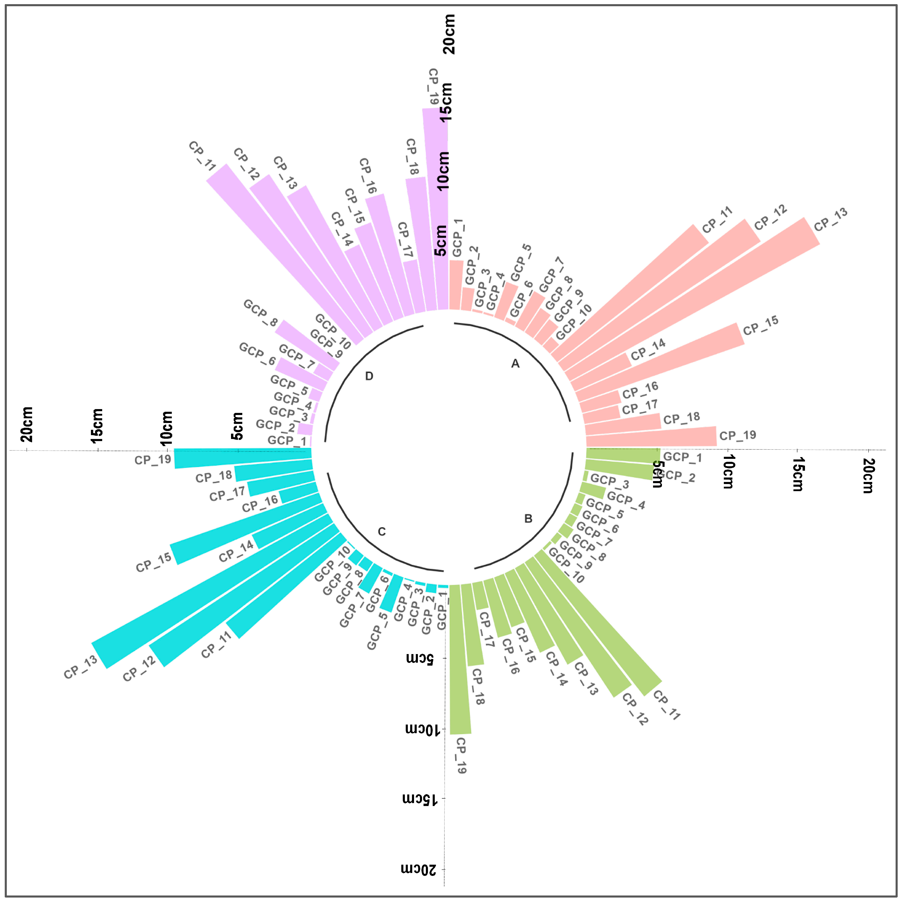
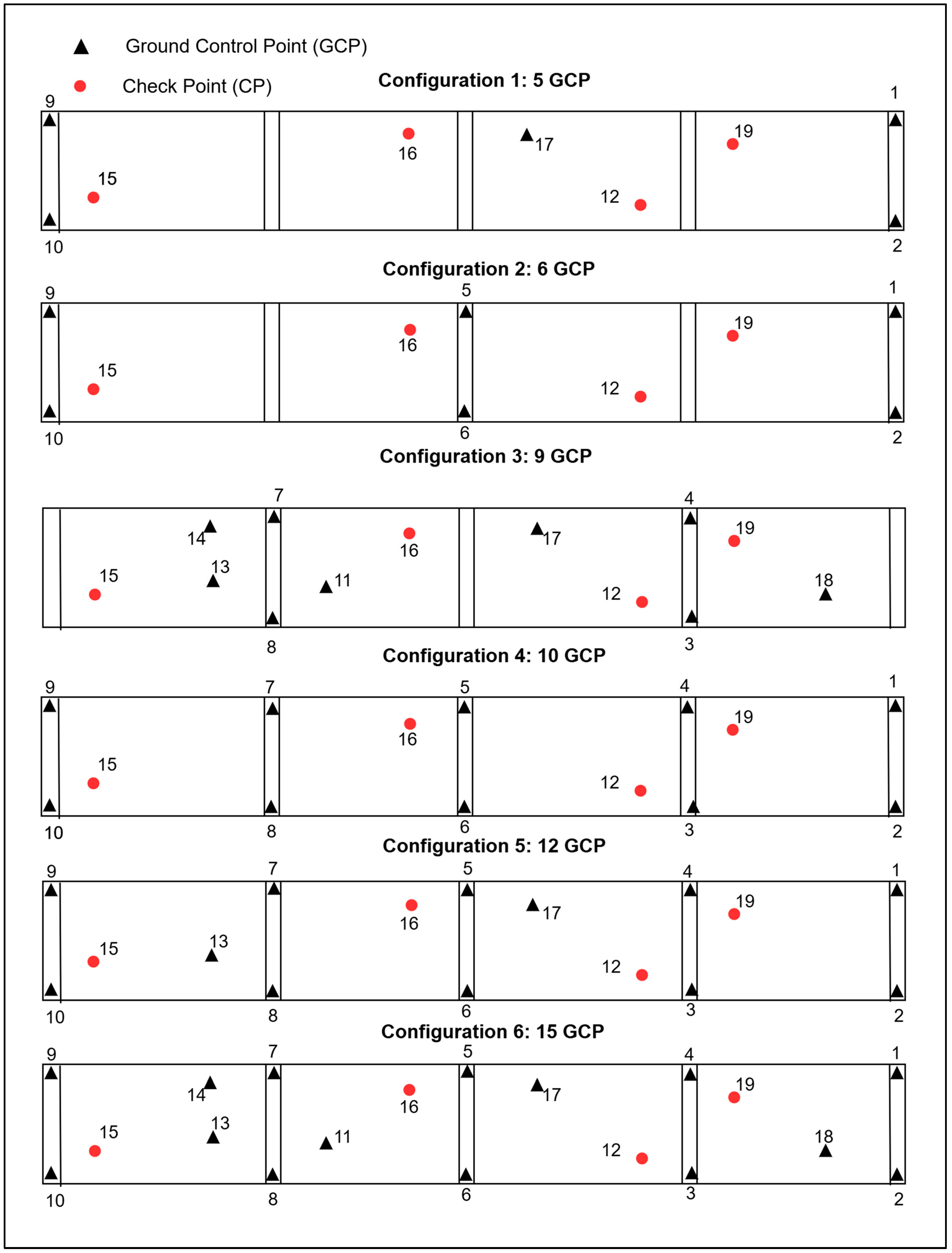
- Configuration 1: 19.8 cm, 24 cm, and 31 cm; Configuration 2: 36 cm, 20 cm, and 41 cm; Configuration 3: 21 cm, 26 cm, and 33 cm; Configuration 4: 4 cm, 9.7 cm, and 10.4 cm;
- Configuration 5: 3.9 cm, 9.7 cm, and 10.4 cm; Configuration 6: 3.9 cm, 9.7 cm, and 10.4 cm. Configurations 1 and 3 exhibited the highest RMSE values. In contrast, Configurations 4, 5, and 6 yielded the best results, with low and nearly identical error values. In Configuration 3, all of the GCPs were positioned along the block’s edges, within the standard overlap zone used for the georeferencing of each flight.
4. Discussion
4.1. Flight Scenarios
4.2. Internal Camera Parameters and Block a Priori Accuracy
4.3. GCPs and CPs Distribution
4.4. Limitations and Potential Solutions
4.5. Terrain Complexity
5. Conclusions
Author Contributions
Funding
Institutional Review Board Statement
Informed Consent Statement
Data Availability Statement
Acknowledgments
Conflicts of Interest
References
- Escalante Torrado, J.O.; Cáceres Jiménez, J.J.; Porras Díaz, H. Orthomosaics and Digital Elevation Models Generated from Images Taken with UAV Systems. Tecnura 2016, 20, 119–140. [Google Scholar]
- Sanz-Ablanedo, E.; Chandler, J.H.; Rodríguez-Pérez, J.R.; Ordóñez, C. Accuracy of Unmanned Aerial Vehicle (UAV) and SfM Photogrammetry Survey as a Function of the Number and Location of Ground Control Points Used. Remote Sens. 2018, 10, 1606. [Google Scholar] [CrossRef]
- Mancini, F.; Dubbini, M.; Gattelli, M.; Stecchi, F.; Fabbri, S.; Gabbianelli, G. Using Unmanned Aerial Vehicles (UAV) for High-Resolution Reconstruction of Topography: The Structure from Motion Approach on Coastal Environments. Remote Sens. 2013, 5, 6880–6898. [Google Scholar] [CrossRef]
- Fonstad, M.A.; Dietrich, J.T.; Courville, B.C.; Jensen, J.L.; Carbonneau, P.E. Topographic Structure from Motion: A New Development in Photogrammetric Measurement. Earth Surf. Process. Landf. 2013, 38, 421–430. [Google Scholar] [CrossRef]
- Colomina, I.; Molina, P. Unmanned Aerial Systems for Photogrammetry and Remote Sensing: A Review. ISPRS J. Photogramm. Remote Sens. 2014, 92, 79–97. [Google Scholar] [CrossRef]
- Carrera-Hernández, J.J.; Levresse, G.; Lacan, P. Is UAV-SfM Surveying Ready to Replace Traditional Surveying Techniques? Int. J. Remote Sens. 2020, 41, 4818–4835. [Google Scholar] [CrossRef]
- Varbla, S.; Puust, R.; Ellmann, A. Accuracy Assessment of RTK-GNSS Equipped UAV Conducted as-Built Surveys for Construction Site Modelling. Surv. Rev. 2020, 53, 477–492. [Google Scholar] [CrossRef]
- Zeybek, M. Accuracy Assessment of Direct Georeferencing UAV Images with Onboard Global Navigation Satellite System and Comparison of CORS/RTK Surveying Methods. Meas. Sci. Technol. 2021, 32, 065402. [Google Scholar] [CrossRef]
- Yurtseven, H. Comparison of GNSS-, TLS- and Different Altitude UAV-Generated Datasets on the Basis of Spatial Differences. ISPRS Int. J. Geo-Inf. 2019, 8, 175. [Google Scholar] [CrossRef]
- Gindraux, S.; Boesch, R.; Farinotti, D.; Melgani, F.; Nex, F.; Kerle, N.; Thenkabail, P. Accuracy Assessment of Digital Surface Models from Unmanned Aerial Vehicles’ Imagery on Glaciers. Remote Sens. 2017, 9, 186. [Google Scholar] [CrossRef]
- Pires, A.; Chaminé, H.I.; Nunes, J.C.; Borges, P.A.; Garcia, A.; Sarmento, E.; Antunes, M.; Salvado, F.; Rocha, F. New Mapping Techniques on Coastal Volcanic Rock Platforms Using UAV LiDAR Surveys in Pico Island, Azores (Portugal). In Volcanic Rocks and Soils; CRC Press: Boca Raton, FL, USA, 2015; p. 181. [Google Scholar]
- Ortíz-Rodríguez, A.J.; Muñoz-Robles, C.; Rodríguez-Herrera, J.G.; Osorio-Carmona, V.; Barbosa-Briones, E. Effect of DEM Resolution on Assessing Hydrological Connectivity in Tropical and Semi-Arid Basins of Central Mexico. J. Hydrol. 2022, 612, 128104. [Google Scholar] [CrossRef]
- Wang, J.; Qin, Z.; Zhao, G.; Li, B.; Gao, C. Scale Effect Analysis of Basin Topographic Features Based on Spherical Grid and DEM: Taking the Yangtze River Basin as an Example. Yingyong Jichu Yu Gongcheng Kexue Xuebao/J. Basic Sci. Eng. 2022, 30, 1109–1120. [Google Scholar] [CrossRef]
- Kastridis, A.; Kirkenidis, C.; Sapountzis, M. An Integrated Approach of Flash Flood Analysis in Ungauged Mediterranean Watersheds Using Post-Flood Surveys and Unmanned Aerial Vehicles. Hydrol. Process. 2020, 34, 4920–4939. [Google Scholar] [CrossRef]
- Abdelal, Q.; Al-Rawabdeh, A.; Al Qudah, K.; Hamarneh, C.; Abu-Jaber, N. Hydrological Assessment and Management Implications for the Ancient Nabataean Flood Control System in Petra, Jordan. J. Hydrol. 2021, 601, 126583. [Google Scholar] [CrossRef]
- Dávila-Hernández, S.; González-Trinidad, J.; Júnez-Ferreira, H.E.; Bautista-Capetillo, C.F.; Morales de Ávila, H.; Cázares Escareño, J.; Ortiz-Letechipia, J.; Robles Rovelo, C.O.; López-Baltazar, E.A. Effects of the Digital Elevation Model and Hydrological Processing Algorithms on the Geomorphological Parameterization. Water 2022, 14, 2363. [Google Scholar] [CrossRef]
- Mora Mur, D.; Ibarra Benlloch, P.; Ferrer, D.B.; Echeverría Arnedo, M.T.; Losada García, J.A.; Ojeda, A.O.; Sánchez Fabre, M. Paisaje y SIG: Aplicación a Los Embalses de La Cuenca Del Ebro. In Análisis Espacial y Representación Geográfica: Innovación y Aplicación; Departamento de Geografía y Ordenación del Territorio: Zapopan, Mexico, 2015. [Google Scholar]
- Li, Z.; Xu, X.; Ren, J.; Li, K.; Kang, W. Vertical Slip Distribution along Immature Active Thrust and Its Implications for Fault Evolution: A Case Study from Linze Thrust, Hexi Corridor. Diqiu Kexue-Zhongguo Dizhi Daxue Xuebao/Earth Sci.-J. China Univ. Geosci. 2022, 47, 831–843. [Google Scholar] [CrossRef]
- Wang, Y.; Dong, P.; Zhu, Y.; Shen, J.; Liao, S. Geomorphic Analysis of Xiadian Buried Fault Zone in Eastern Beijing Plain Based on SPOT Image and Unmanned Aerial Vehicle (UAV) Data. Geomat. Nat. Hazards Risk 2021, 12, 261–278. [Google Scholar] [CrossRef]
- Bi, H.; Zheng, W.; Lei, Q.; Zeng, J.; Zhang, P.; Chen, G. Surface Slip Distribution Along the West Helanshan Fault, Northern China, and Its Implications for Fault Behavior. J. Geophys. Res. Solid Earth 2020, 125, e2020JB019983. [Google Scholar] [CrossRef]
- Lee, C.F.; Tsao, T.C.; Huang, W.K.; Lin, S.C.; Yin, H.Y. Landslide Mapping and Geomorphologic Change Based on a Sky-View Factor and Local Relief Model: A Case Study in Hongye Village, Taitung. J. Chin. Soil Water Conserv. 2018, 49, 27–39. [Google Scholar] [CrossRef]
- Amin, P.; Ghalibaf, M.A.; Hosseini, M. Modeling for Temporal Land Subsidence Forecasting Using Field Surveying with Complementary Drone Imagery Testing in Yazd Plain, Iran. Environ. Monit. Assess. 2022, 194, 29. [Google Scholar] [CrossRef]
- Betz, F.; Lauermann, M.; Cyffka, B. Geomorphological Characterization of Rivers Using Virtual Globes and Digital Elevation Data: A Case Study from the Naryn River in Kyrgyzstan. Int. J. Geoinform. 2021, 17, 47–55. [Google Scholar] [CrossRef]
- Carbonell-Rivera, J.P.; Torralba, J.; Estornell, J.; Ruiz, L.Á.; Crespo-Peremarch, P. Classification of Mediterranean Shrub Species from UAV Point Clouds. Remote Sens. 2022, 14, 199. [Google Scholar] [CrossRef]
- Nevalainen, O.; Honkavaara, E.; Tuominen, S.; Viljanen, N.; Hakala, T.; Yu, X.; Hyyppä, J.; Saari, H.; Pölönen, I.; Imai, N.N.; et al. Individual Tree Detection and Classification with UAV-Based Photogrammetric Point Clouds and Hyperspectral Imaging. Remote Sens. 2017, 9, 185. [Google Scholar] [CrossRef]
- DJI Fixed-Wing vs Multirotor: Which Drone Should You Choose for Aerial Surveying? Available online: https://enterprise-insights.dji.com/blog/fixed-wing-vs-multirotor-drone-surveying (accessed on 31 January 2025).
- Yan, Y.; Lv, Z.; Yuan, J.; Chai, J. Analysis of Power Source of Multirotor UAVs. Int. J. Robot. Autom. 2019, 34, 563–571. [Google Scholar] [CrossRef]
- Jiménez-Jiménez, S.I.; Ojeda-Bustamante, W.; Marcial-Pablo, M.D.J.; Enciso, J. Digital Terrain Models Generated with Low-Cost UAV Photogrammetry: Methodology and Accuracy. ISPRS Int. J. Geo-Inf. 2021, 10, 285. [Google Scholar] [CrossRef]
- Nex, F.; Remondino, F. UAV for 3D Mapping Applications: A Review. Appl. Geomat. 2014, 6, 1–15. [Google Scholar] [CrossRef]
- Quispe, O.C. GSD Analysis for Generating Cartography Using Drone Technology; Huaca of San Marcos University: Lima, Peru, 2015; Volume 18. [Google Scholar]
- Pix4D, S.A. USER MANUAL Pix4Dmapper 4.1; Pix4D: Lausanne, Switzerland, 2017; 305p. [Google Scholar]
- Agisoft Agisoft PhotoScan User Manual—Professional Edition, Version 1.2. Available online: https://www.agisoft.com/pdf/photoscan-pro_1_2_en.pdf (accessed on 2 June 2021).
- İncekara, A.H.; Seker, D.Z. Rolling Shutter Effect on the Accuracy of Photogrammetric Product Produced by Low-Cost UAV. Int. J. Environ. Geoinform. 2021, 8, 549–553. [Google Scholar] [CrossRef]
- Zhou, Y.; Daakir, M.; Rupnik, E.; Pierrot-Deseilligny, M. A Two-Step Approach for the Correction of Rolling Shutter Distortion in UAV Photogrammetry. ISPRS J. Photogramm. Remote Sens. 2020, 160, 51–66. [Google Scholar] [CrossRef]
- Vautherin, J.; Rutishauser, S.; Schneider-Zapp, K.; Choi, H.F.; Chovancova, V.; Glass, A.; Strecha, C. Photogrammetric accuracy and modeling of rolling shutter cameras. ISPRS Ann. Photogramm. Remote Sens. Spat. Inf. Sci. 2016, III-3, 139–146. [Google Scholar] [CrossRef]
- Sadeq, H.A. Accuracy Assessment Using Different UAV Image Overlaps. J. Unmanned Veh. Syst. 2019, 7, 175–193. [Google Scholar] [CrossRef]
- Yang, B.; Ali, F.; Zhou, B.; Li, S.; Yu, Y.; Yang, T.; Liu, X.; Liang, Z.; Zhang, K. A Novel Approach of Efficient 3D Reconstruction for Real Scene Using Unmanned Aerial Vehicle Oblique Photogrammetry with Five Cameras. Comput. Electr. Eng. 2022, 99, 107804. [Google Scholar] [CrossRef]
- James, M.R.; Robson, S. Mitigating Systematic Error in Topographic Models Derived from UAV and Ground-Based Image Networks. Earth Surf. Process. Landf. 2014, 39, 1413–1420. [Google Scholar] [CrossRef]
- Mora, O.E.; Suleiman, A.; Chen, J.; Pluta, D.; Okubo, M.H.; Josenhans, R. Comparing SUAS Photogrammetrically-Derived Point Clouds with GNSS Measurements and Terrestrial Laser Scanning for Topographic Mapping. Drones 2019, 3, 64. [Google Scholar] [CrossRef]
- Rossi, P.; Mancini, F.; Dubbini, M.; Mazzone, F.; Capra, A. Combining Nadir and Oblique UAV Imagery to Reconstruct Quarry Topography: Methodology and Feasibility Analysis. Eur. J. Remote Sens. 2017, 50, 211–221. [Google Scholar] [CrossRef]
- Santise, M.; Fornari, M.; Forlani, G.; Roncella, R. Evaluation of DEM Generation Accuracy from UAS Imagery. Int. Arch. Photogramm. Remote Sens. Spat. Inf. Sci. 2014, XL-5, 529–536. [Google Scholar] [CrossRef]
- Jiménez-Jiménez, S.I.; Ojeda-Bustamante, W.; Ontiveros-Capurata, R.E.; Flores-Velázquez, J.; Marcial-Pablo, M.d.J.; Robles-Rubio, B.D. Quantification of the Error of Digital Terrain Models Derived from Images Acquired with UAV. Ing. Agrícola Y Biosist. 2017, 9, 85–100. [Google Scholar] [CrossRef]
- Ferrer-González, E.; Agüera-Vega, F.; Carvajal-Ramírez, F.; Martínez-Carricondo, P. UAV Photogrammetry Accuracy Assessment for Corridor Mapping Based on the Number and Distribution of Ground Control Points. Remote Sens. 2020, 12, 2447. [Google Scholar] [CrossRef]
- Ewertowski, M.W.; Tomczyk, A.M.; Evans, D.J.A.; Roberts, D.H.; Ewertowski, W. Operational Framework for Rapid, Very-High Resolution Mapping of Glacial Geomorphology Using Low-Cost Unmanned Aerial Vehicles and Structure-from-Motion Approach. Remote Sens. 2019, 11, 65. [Google Scholar] [CrossRef]
- Arévalo-Verjel, A.N.; Lerma, J.L.; Prieto, J.F.; Carbonell-Rivera, J.P.; Fernández, J. Estimation of the Block Adjustment Error in UAV Photogrammetric Flights in Flat Areas. Remote Sens. 2022, 14, 2877. [Google Scholar] [CrossRef]
- DroneDeploy.com. Drone Deploy. Available online: https://help.dronedeploy.com/hc/en-us/articles/1500004964162-3D-Models (accessed on 5 April 2021).
- AEMET España—Agencia Estatal de Meteorología. Gobierno de España. Available online: https://www.aemet.es/es/eltiempo/prediccion/espana (accessed on 27 November 2022).
- Instituto Geográfico Nacional Centro de Descargas Del CNIG (IGN). Available online: http://centrodedescargas.cnig.es/CentroDescargas/index.jsp (accessed on 22 June 2022).
- Fernandez, J.; Prieto, J.F.; Escayo, J.; Camacho, A.G.; Luzón, F.; Tiampo, K.F.; Palano, M.; Abajo, T.; Pérez, E.; Velasco, J.; et al. Modeling the Two- and Three-Dimensional Displacement Field in Lorca, Spain, Subsidence and the Global Implications. Sci. Rep. 2018, 8, 14782. [Google Scholar] [CrossRef]
- Velasco, J.; Herrero, T.; Molina, I.; López, J.; Pérez-Martín, E.; Prieto, J. Methodology for Designing, Observing and Computing of Underground Geodetic Networks of Large Tunnels for High-Speed Railways. Inf. Construcción 2015, 67, e076. [Google Scholar] [CrossRef][Green Version]
- Geosystems Leica Infinity Surveying Software|Leica Geosystems. Available online: https://leica-geosystems.com/products/gnss-systems/software/leica-infinity (accessed on 27 May 2023).
- Boehm, J.; Werl, B.; Schuh, H. Troposphere Mapping Functions for GPS and Very Long Baseline Interferometry from European Centre for Medium-Range Weather Forecasts Operational Analysis Data. J. Geophys. Res. Solid Earth 2006, 111, 2406. [Google Scholar] [CrossRef]
- Velasco-Gómez, J.; Prieto, J.F.; Molina, I.; Herrero, T.; Fábrega, J.; Pérez-Martín, E. Use of the Gyrotheodolite in Underground Networks of Long High-Speed Railway Tunnels. Surv. Rev. 2016, 48, 329–337. [Google Scholar] [CrossRef]
- Krzykowska, K.; Siergiejczyk, M.; Rosiński, A. Influence of Selected External Factors on Satellite Navigation Signal Quality. In Safety and Reliability–Safe Societies in a Changing World; CRC Press: Boca Raton, FL, USA, 2018; pp. 701–705. [Google Scholar]
- Wierzbicki, D.; Kedzierski, M.; Fryskowska, A. Assesment of the influence of UAV image quality on the orthophoto production. Int. Arch. Photogramm. Remote Sens. Spat. Inf. Sci. 2015, XL-1/W4, 1–8. [Google Scholar] [CrossRef]
- Boletín Oficial Del Estado (BOE). Real Decreto 1036/2017 de 15 de Diciembre; Government of Spain–Ministry of Transport and Sustainable Mobility: Madrid, Spain, 2015; p. 316. [Google Scholar]
- Lerma, J.L.G. Fotogrametría Moderna: Analítica y Digital; Universitat Politècnica de València: València, Spain, 2002; p. 560. ISBN 978-84-9705-210-8. [Google Scholar]
- Kraus, K. Photogrammetry. Volume 1, Fundamentals and Standard Processes; Dümmler: Bonn, Germany, 1993; p. 389. ISBN 3427786846. [Google Scholar]
- Kraus, K. Photogrammetry. Volume 2, Advanced Methods and Applications; Jansa, J., Kager, H., Eds.; Dümmler: Bonn, Germany, 1997; p. 459. ISBN 3427786943. [Google Scholar]
- Shoab, M.; Singh, V.K.; Ravibabu, M.V. High-Precise True Digital Orthoimage Generation and Accuracy Assessment Based on UAV Images. J. Indian Soc. Remote Sens. 2022, 50, 613–622. [Google Scholar] [CrossRef]
- Liu, Y.; Zheng, X.; Ai, G.; Zhang, Y.; Zuo, Y. Generating a High-Precision True Digital Orthophoto Map Based on UAV Images. ISPRS Int. J. Geo-Inf. 2018, 7, 333. [Google Scholar] [CrossRef]
- Agisoft Aerial Data Processing (with GCPs)—Orthomosaic&DEM Generation: Helpdesk Portal. Available online: https://agisoft.freshdesk.com/support/solutions/articles/31000153696 (accessed on 30 July 2021).
- Luhmann, T.; Fraser, C.; Maas, H.G. Sensor Modelling and Camera Calibration for Close-Range Photogrammetry. ISPRS J. Photogramm. Remote Sens. 2016, 115, 37–46. [Google Scholar] [CrossRef]
- Bruno, N.; Forlani, G. Experimental Tests and Simulations on Correction Models for the Rolling Shutter Effect in UAV Photogrammetry. Remote Sens. 2023, 15, 2391. [Google Scholar] [CrossRef]
- Federal Geographic Data Committee. Geospatial Positioning Accuracy Standards Part 3: National Standard for Spatial Data Accuracy Subcommittee for Base Cartographic Data Federal Geographic Data Committee; Federal Geographic Data Committee: Virginia, NV, USA, 1998. [Google Scholar]
- Rock, G.; Ries, J.B.; Udelhoven, T. Sensitivity Analysis of UAV-Photogrammetry for Creating Digital Elevation Models (DEM). Int. Arch. Photogramm. Remote Sens. Spat. Inf. Sci. 2012, XXXVIII-1/C22, 69–73. [Google Scholar] [CrossRef]
- Barba, S.; Barbarella, M.; Di Benedetto, A.; Fiani, M.; Gujski, L.; Limongiello, M. Accuracy Assessment of 3D Photogrammetric Models from an Unmanned Aerial Vehicle. Drones 2019, 3, 79. [Google Scholar] [CrossRef]
- Harwin, S.; Lucieer, A.; Osborn, J. The Impact of the Calibration Method on the Accuracy of Point Clouds Derived Using Unmanned Aerial Vehicle Multi-View Stereopsis. Remote Sens. 2015, 7, 11933–11953. [Google Scholar] [CrossRef]
- Zimmerman, T.; Jansen, K.; Miller, J. Analysis of UAS Flight Altitude and Ground Control Point Parameters on DEM Accuracy along a Complex, Developed Coastline. Remote Sens. 2020, 12, 2305. [Google Scholar] [CrossRef]
- Liu, X.; Lian, X.; Yang, W.; Wang, F.; Han, Y.; Zhang, Y. Accuracy Assessment of a UAV Direct Georeferencing Method and Impact of the Configuration of Ground Control Points. Drones 2022, 6, 30. [Google Scholar] [CrossRef]

| Ref. | Area (km2) | Image Type | Flight Height (m) | Camera Model | Shutter Model | Focal Length (mm) | Overlap (for-ward-lateral) (%) | GCPs–CPs | GSD (cm/pix) | RMSE/GSD | ||
|---|---|---|---|---|---|---|---|---|---|---|---|---|
| XY | Z | 3D | ||||||||||
| [9] | 0.006 | Nadir | 25-50-120 | Sony Exmor R BSI 1/2. 3 | Electronic | 20 | 95–95 | 15–35 | 4.8 | 2.2 | 1.9 | 3 |
| [39] | 0.017 | Nadir | 45 | Phantom 4 Pro | Mechanic | 24 | 85–75 | 5–19 | 0.75 | 2.6 | 4.3 | 5.1 |
| [40] | 0.09 | Nadir and oblique | 50 | Canon EOS 550D | Mechanic | 25 | 90–90 | 18–5 | 1 | 2 | 2 | 2.9 |
| [36] | 0.09 | Nadir and oblique | 60 | Canon IXUS160 | Electronic | 28 | 90–45 | 6–41 | 1.4 | 0.9 | 2.6 | 2.8 |
| [41] | 0.25 | Nadir | 140 | Sony NEX 5 | Electronic | 35 | 80–40 | 35–101 | 4 | 1.6 | 1.1 | 2 |
| [42] | 0.370 | Nadir | 92 | Sony NEX-7 | dual | 16 | 75–75 | 11–12 | 2 | 1.8 | 3 | 3.5 |
| [43] | 0.40 | Nadir | 65 | Phantom 4 Pro | Mechanic | 24 | 80–60 | 18–29 | 1.75 | 1.6 | 3.2 | 3.5 |
| [8] | 0.024 | Nadir and oblique | 75–100 | Phantom 4 RTK | Mechanic | 24 | 70–10 | N/A | 2.7 | 0.7 | 1.8 | 1.9 |
| [44] | 1 | Nadir and oblique | 53 | Sony Exmor R BSI 1/2. 3 | Electronic | 20 | 80–80 | 30–15 | 1.9 | N/A | N/A | 4.2 |
| [37] | 2.1 | Nadir and oblique | 100 | DSC-QX100 | Electronic | 37.1 | 80–75 | 6–7 | 2 | 1.5 | 1.8 | 2.3 |
| [45] * | 0.19 | Nadir | 120 | FC 300X | Electronic | 20 | 80–75 | 4–2 | 5.18 | 2.4 | 1 | 2.6 |
| Mean | 1.7 | 2.3 | 3.1 | |||||||||
| Median | 1.7 | 2 | 2.9 | |||||||||
| Minimum | 0.7 | 1.1 | 1.9 | |||||||||
| exp | Maximum | 2.6 | 4.3 | 5.1 | ||||||||
| Block | Strip Type | Area (km2) | Forward Overlap | Lateral Overlap | Flight Height (m) | GSD (cm/pix) | No of Images |
|---|---|---|---|---|---|---|---|
| Block 1 | Forward strips | 0.19 | 80% | 60% | hf = 120 | 2.6 | 191 |
| Block 1 | Cross strip 1 | 0.019 | 80% | 60% | hc = 110 | 2.4 | 19 |
| Block 1 | Perimeter 3D | 80% | 60% | hf = 120 | 2.6 | 74 | |
| Blocks 1 and 2 | Cross strip 2 | 0.019 | 80% | 60% | hc = 110 | 2.4 | 19 |
| Block 2 | Forward strips | 0.19 | 80% | 60% | hf = 120 | 2.6 | 179 |
| Blocks 2 and 3 | Cross strip 3 | 0.019 | 80% | 60% | hc = 110 | 2.4 | 19 |
| Block 2 | Perimeter 3D | 80% | 60% | hf = 120 | 2.6 | 69 | |
| Block 3 | Forward strips | 0.23 | 80% | 60% | hf = 120 | 2.6 | 215 |
| Blocks 3 and 4 | Cross strip 4 | 0.019 | 80% | 60% | hc = 110 | 2.4 | 19 |
| Block 3 | Perimeter 3D | 80% | 60% | hf = 120 | 2.6 | 78 | |
| Block 4 | Forward strips | 0.19 | 80% | 60% | hf = 120 | 2.6 | 177 |
| Block 4 | Cross strip 5 | 0.019 | 80% | 60% | hc = 110 | 2.4 | 19 |
| Block 4 | Perimeter 3D | 80% | 60% | hf = 120 | 2.6 | 68 | |
| Total | 0.8 | 1106 |
| Point | Coordinates | Std. Deviation | ||||
|---|---|---|---|---|---|---|
| Northing | Easting | Height | Northing | Easting | Height | |
| 1 GCP | 4,167,120.872 | 619,065.846 | 290.896 | 0.004 | 0.003 | 0.011 |
| 2 GCP | 4,167,301.180 | 619,251.921 | 291.062 | 0.004 | 0.003 | 0.010 |
| 3 GCP | 4,167,441.058 | 618,678.165 | 293.067 | 0.020 | 0.017 | 0.055 |
| 4 GCP | 4,167,651.253 | 618,800.408 | 293.272 | 0.006 | 0.005 | 0.016 |
| 5 GCP | 4,168,020.890 | 618,440.211 | 295.557 | 0.006 | 0.005 | 0.012 |
| 6 GCP | 4,167,885.738 | 618,252.823 | 296.378 | 0.006 | 0.006 | 0.014 |
| 7 GCP | 4,168,445.382 | 617,870.494 | 301.173 | 0.005 | 0.004 | 0.012 |
| 8 GCP | 4,168,275.535 | 617,743.737 | 301.277 | 0.006 | 0.003 | 0.011 |
| 9 GCP | 4,168,820.872 | 617,556.983 | 306.673 | 0.007 | 0.007 | 0.019 |
| 10 GCP | 4,168,643.303 | 617,372.606 | 305.973 | 0.014 | 0.010 | 0.026 |
| 11 CP | 4,168,139.300 | 617,949.391 | 299.751 | 0.009 | 0.008 | 0.018 |
| 12 CP | 4,167,644.991 | 618,565.766 | 294.184 | 0.005 | 0.004 | 0.013 |
| 13 CP | 4,168,465.150 | 617,639.596 | 303.453 | 0.006 | 0.005 | 0.012 |
| 14 CP | 4,168,587.195 | 617,782.779 | 301.789 | 0.003 | 0.003 | 0.010 |
| 15 CP | 4,168,564.801 | 617,496.087 | 305.331 | 0.007 | 0.005 | 0.014 |
| 16 CP | 4,168,060.373 | 618,259.190 | 296.853 | 0.005 | 0.005 | 0.011 |
| 17 CP | 4,167,871.156 | 618,528.526 | 294.304 | 0.006 | 0.004 | 0.010 |
| 18 CP | 4,167,325.170 | 618,839.696 | 292.306 | 0.006 | 0.006 | 0.021 |
| 19 CP | 4,167,568.703 | 618,805.363 | 293.155 | 0.005 | 0.004 | 0.010 |
| ALHA | 4,185,231.011 | 636,738.932 | 201.797 | 0.001 | 0.001 | 0.002 |
| LRCA | 4,168,655.115 | 614,704.901 | 332.215 | 0.001 | 0.000 | 0.001 |
| MAZA | 4,162,049.758 | 649,154.772 | 55.072 | 0.000 | 0.000 | 0.001 |
| Shutter Type | Scenario | RMSE x | RMSE y | RMSE z |
|---|---|---|---|---|
| Fast Readout | A | 40 | 33 | 49 |
| B | 38 | 38 | 38 | |
| C | 39 | 31 | 28 | |
| D | 30 | 33 | 32 | |
| Rolling shutter lineal | A | 1.7 | 4.4 | 10.7 |
| B | 2.9 | 3.4 | 6.7 | |
| C | 1.8 | 4.2 | 9.9 | |
| D | 3.2 | 4.1 | 10.9 |
| Scenario | Parameters | Focal Length [pix] | Principal Point x [pix] | Principal Point y [pix] | R1 | R2 | R3 | T1 | T2 | Result 1 |
|---|---|---|---|---|---|---|---|---|---|---|
| A | Initial Values | 4564.399 | 2698.159 | 1910.765 | −0.004 | −0.043 | 0.087 | −0.003 | 0.004 | 3.56% |
| Optimised Values | 4741.210 | 2639.595 | 1942.754 | −0.006 | 0.014 | −0.015 | −0.001 | 0.001 | ||
| Uncertainties (Sigma) | 15.865 | 0.541 | 1.503 | 0.000 | 0.000 | 0.001 | 0.000 | 0.000 | ||
| B | Initial Values | 4559.840 | 2643.290 | 1912.470 | −0.005 | 0.009 | −0.008 | −0.001 | 0.004 | 0.34% |
| Optimised Values | 4554.479 | 2640.732 | 1916.975 | −0.005 | 0.01 | −0.009 | −0.001 | 0.001 | ||
| Uncertainties (Sigma) | 0.718 | 0.111 | 0.745 | 0.000 | 0.000 | 0.000 | 0.000 | 0.000 | ||
| C | Initial Values | 4564.399 | 2698.159 | 1910.765 | −0.004 | −0.043 | 0.087 | −0.003 | 0.004 | 3.30% |
| Optimised Values | 4725.975 | 2638.960 | 1945.875 | −0.006 | 0.014 | −0.015 | −0.001 | 0.001 | ||
| Uncertainties (Sigma) | 14.225 | 0.484 | 1.421 | 0.000 | 0.000 | 0.001 | 0.000 | 0.000 | ||
| D | Initial Values | 4564.399 | 2698.159 | 1910.765 | −0.004 | −0.043 | 0.087 | −0.003 | 0.004 | 0.16% |
| Optimised Values | 4560.586 | 2642.156 | 1910.781 | −0.005 | 0.007 | −0.005 | −0.001 | 0.001 | ||
| Uncertainties (Sigma) | 0.714 | 0.116 | 0.752 | 0.000 | 0.000 | 0.000 | 0.000 | 0.000 |
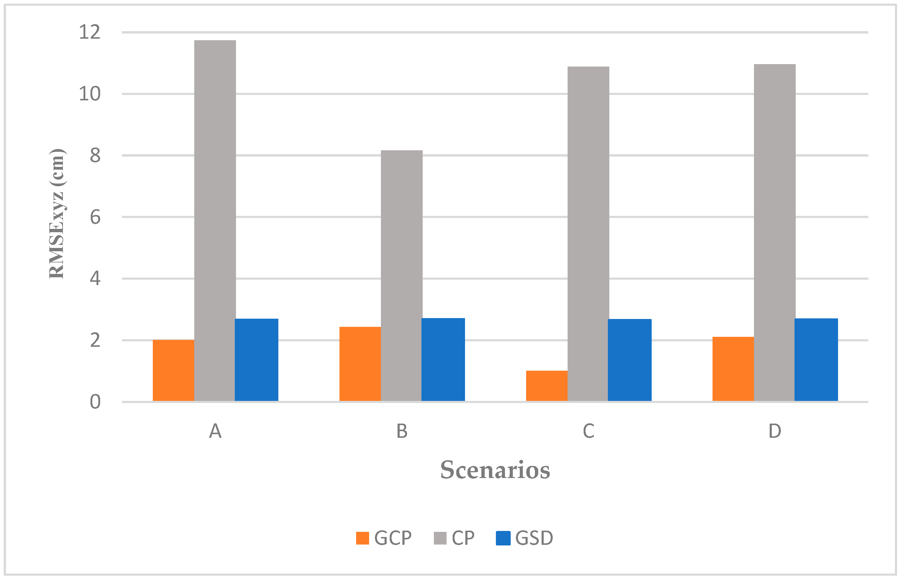
| Scenario | GSD [cm] | Reproj. Error σo | RMSE GCPxy | RMSE CPxy | RMSE GCPz | RMSE CPz | RMSE GCPxyz | RMSE CPxyz | CPxy/ GSD | CPz/ GSD | CPxyz/ GSD |
|---|---|---|---|---|---|---|---|---|---|---|---|
| A | 2.7 | 0.3 | 0.3 | 4.8 | 2 | 10.7 | 2.0 | 11.7 | 1.8 | 4.0 | 4.3 |
| B | 2.7 | 0.4 | 0.7 | 4.6 | 2.3 | 6.8 | 2.4 | 8.2 | 1.7 | 2.5 | 3.0 |
| C | 2.7 | 0.4 | 0.3 | 4.5 | 1 | 9.9 | 1.0 | 10.9 | 1.7 | 3.7 | 4.0 |
| D | 2.7 | 0.5 | 0.9 | 5.3 | 2 | 10.9 | 2.1 | 11.0 | 2.0 | 3.5 | 4.1 |
| Scenario | CP | CP | CP |
|---|---|---|---|
| A | 1.0 | 1.5 | 1.8 |
| B | 1.0 | 0.9 | 1.3 |
| C | 0.9 | 1.4 | 1.7 |
| D | 1.1 | 1.5 | 1.9 |
| mean | 1.0 | 1.3 | 1.7 |
| std | 0.1 | 0.3 | 0.2 |
Disclaimer/Publisher’s Note: The statements, opinions and data contained in all publications are solely those of the individual author(s) and contributor(s) and not of MDPI and/or the editor(s). MDPI and/or the editor(s) disclaim responsibility for any injury to people or property resulting from any ideas, methods, instructions or products referred to in the content. |
© 2025 by the authors. Licensee MDPI, Basel, Switzerland. This article is an open access article distributed under the terms and conditions of the Creative Commons Attribution (CC BY) license (https://creativecommons.org/licenses/by/4.0/).
Share and Cite
Arévalo-Verjel, A.N.; Lerma, J.L.; Carbonell-Rivera, J.P.; Prieto, J.F.; Fernández, J. Assessment of Photogrammetric Performance Test on Large Areas by Using a Rolling Shutter Camera Equipped in a Multi-Rotor UAV. Appl. Sci. 2025, 15, 5035. https://doi.org/10.3390/app15095035
Arévalo-Verjel AN, Lerma JL, Carbonell-Rivera JP, Prieto JF, Fernández J. Assessment of Photogrammetric Performance Test on Large Areas by Using a Rolling Shutter Camera Equipped in a Multi-Rotor UAV. Applied Sciences. 2025; 15(9):5035. https://doi.org/10.3390/app15095035
Chicago/Turabian StyleArévalo-Verjel, Alba Nely, José Luis Lerma, Juan Pedro Carbonell-Rivera, Juan F. Prieto, and José Fernández. 2025. "Assessment of Photogrammetric Performance Test on Large Areas by Using a Rolling Shutter Camera Equipped in a Multi-Rotor UAV" Applied Sciences 15, no. 9: 5035. https://doi.org/10.3390/app15095035
APA StyleArévalo-Verjel, A. N., Lerma, J. L., Carbonell-Rivera, J. P., Prieto, J. F., & Fernández, J. (2025). Assessment of Photogrammetric Performance Test on Large Areas by Using a Rolling Shutter Camera Equipped in a Multi-Rotor UAV. Applied Sciences, 15(9), 5035. https://doi.org/10.3390/app15095035


