Article

Design of Magnetic Concrete for Inductive Power Transfer System in Rail Applications

1
Department of Civil and Environmental Engineering, University of North Carolina at Charlotte, Charlotte, NC 28223, USA
2
Department of Electrical and Computer Engineering, University of North Carolina at Charlotte, Charlotte, NC 28223, USA
3
Deutsche Bahn, Sacramento, CA 95814, USA
*
Author to whom correspondence should be addressed.
Appl. Sci. 2025, 15(9), 4987; https://doi.org/10.3390/app15094987
Submission received: 23 March 2025 / Revised: 17 April 2025 / Accepted: 22 April 2025 / Published: 30 April 2025
(This article belongs to the Section Electrical, Electronics and Communications Engineering)

Abstract

:
Inductive power transfer (IPT) systems are transforming railway infrastructure by enabling efficient, wireless energy transmission for electric locomotives equipped with Li-ion batteries. This technology eliminates the need for overhead power lines and third rails, offering financial and operational advantages over conventional electric propulsion systems. Despite its potential, IPT deployment in rail applications faces significant challenges, including the fragility of materials (i.e., ferrite and Litz wires), thermal management during high-power transfers, and electromagnetic interference (EMI) on the transmitter side. This study discusses several factors affecting IPT efficiency and introduces magnetic concrete as a durable and cost-effective material solution for IPT systems. Magnetic concrete combines soft ferrite powder with water and coarse aggregates to enhance magnetic functionality while maintaining structural strength comparable to conventional concrete. Its durability and optimized magnetic properties promote consistent power transfer efficiency, making it a viable alternative to traditional ferrite cores. A comparative study has been performed on non-magnetic and magnetic concrete (with 33% ferrite powder) using both permeability tests and finite element analysis (FEA). The FEA includes both thermal and electromagnetic simulations using Ansys Maxwell (v.16), revealing that magnetic concrete can improve temperature management and EMI mitigation, and the findings underscore its potential to revolutionize IPT technology by overcoming the limitations of traditional materials and enhancing durability, cost-efficiency, and power transfer efficiency. By addressing the challenges of fragility, thermal management, and shielding of the unique coil topology design presented, this study lays the groundwork for improving IPT infrastructure in sustainable and efficient rail transport systems.

1. Introduction

The development of inductive power transfer (IPT) systems has been suggested as a significant milestone in the evolution of electric railway infrastructure aligning with global efforts to adopt sustainable and efficient methods of electrifying transportation [1,2,3]. Transportation electrification is an important part of decarbonization for a more sustainable environment. IPT systems operate by utilizing electromagnetic fields to enable the wireless transmission of energy, providing an alternative to conventional power supply methods that may include overhead powerline or third rail technologies [4,5,6,7,8,9,10,11,12,13,14,15,16,17,18,19,20,21,22]. The removal of overhead powerlines or third rails has been identified as a major benefit of IPT systems, particularly for electric locomotives equipped with lithium-ion battery technology. These locomotives have been shown to reduce the dependency on complex infrastructure while enhancing safety through the elimination of manual cable connections, which are prone to operational risks [23,24].
The introduction of IPT systems in railway environments has been observed to involve technical challenges that must be addressed to ensure safe implementation. Railways operate under conditions characterized by continuous vibration, mechanical stress, and variable environmental factors [25]. These conditions impose substantial demands on the materials and technologies employed in IPT systems. Ferrite cores, which are widely used in IPT applications due to their magnetic properties, have demonstrated limitations in harsh environments due to their susceptibility to mechanical degradation [26]. This degradation has been found to affect their long-term reliability, necessitating frequent maintenance or replacement [27].
Thermal loads have been observed to compromise the performance of IPT systems, leading to efficiency losses and potential component failures. Without effective thermal management solutions, the increased heat dissipation becomes a critical constraint [28,29]. Another issue associated with IPT technology is electromagnetic interference (EMI), particularly in railway environments where sensitive electronic systems and operational safety protocols must be upheld. Inadequate shielding has been noted to result in electromagnetic leakage, affecting system performance and posing risks to surrounding infrastructure and personnel [30,31].
The deployment of IPT systems for rail applications has necessitated the development of robust ancillary infrastructure. Magnetic concrete has emerged as a viable solution to address several of the above-mentioned issues. This composite material combines the structural properties of traditional concrete with the magnetic characteristics of ferrite particles. By incorporating magnetic functionality into the concrete matrix, this material offers a potential means of improving the durability and operational performance of IPT systems by addressing challenges related to material degradation, thermal management, and electromagnetic shielding while maintaining structural integrity [32]. Ferrite cores form the support system for wireless transfer coils but have been observed to lack the robustness required for prolonged use in railway applications [22]. Heat generation is an inherent problem for IPT, posing risks to material stability, system efficiency, and overall reliability [33,34,35]. Finally, EMI has been identified as a critical obstacle, necessitating the implementation of effective shielding solutions [36].
However, limited attention has been given to understanding the interaction between magnetic concrete and the IPT system, particularly with respect to thermal behavior and electromagnetic shielding in real-world scenarios. Existing studies have largely examined its theoretical properties, including magnetic permeability and compressive strength, within controlled laboratory settings [37,38,39,40]. Studies on heat generation during power transfers have shown evidence of material degradation and system efficiency reduction without suggesting solutions [33,41,42,43,44].
EMI in the deployment of IPT systems without adequate shielding can disrupt nearby electronic systems and compromise operational safety [31,45,46,47,48,49,50,51,52,53,54,55]. The integration of magnetic concrete into transmitter designs has been proposed as a means of enhancing electromagnetic field containment. In general, shielding methods for IPT systems can be categorized into active and passive shielding. Active shielding involves the use of additional coils or circuitry to generate opposing electromagnetic fields, effectively canceling unwanted emissions [56,57,58,59]. In contrast, passive shielding relies on materials with high permeability or conductivity to absorb and redirect stray magnetic fields [60,61].
This paper describes research on the design of magnetic concrete for an IPT system developed for railway applications with a focus on its role in addressing challenges related to material degradation, thermal behavior, and electromagnetic shielding. In this paper, FEA is used to simulate the performance of magnetic concrete, providing insights into its suitability compared to traditional ferrite cores and normal concrete. These simulations are used to analyze temperature distributions, electromagnetic field interactions, and their combined impact on system performance and reliability. Laboratory tests of materials have also been conducted to validate some of the material properties necessary for numerical simulation and material characterization. Finally, a full-scale magnetic slab as an ancillary component of an IPT system has been constructed for validation. By addressing the challenges of fragility, thermal management, and shielding of the unique coil topology design presented, this study lays the groundwork for improving IPT infrastructure in sustainable and efficient rail transport systems.

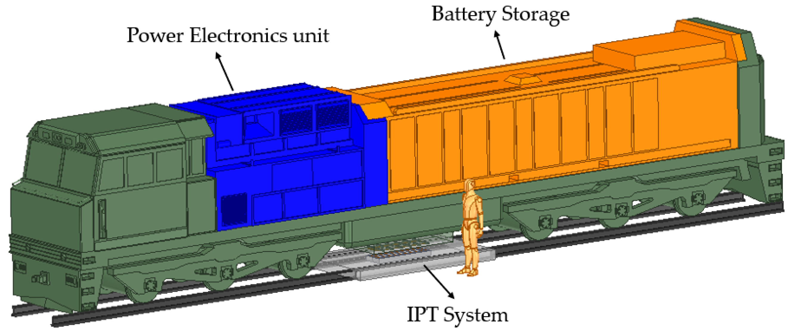
2. IPT System Design

Figure 1 illustrates the static IPT system setup specifically designed for battery electric locomotives. The system employs one or multiple transmitter pads integrated with magnetic concrete strategically placed between the railroad tracks and paired with receiver coils attached directly under the trains. The transmitter coils embedded within the track structure generate a magnetic field using magnetic coils which is supported by the magnetic concrete slab enhancing the magnetic coupling.
While not a subject of the current paper, battery electric train technology employs lithium-ion batteries (LIBs) in racks that connect to the powertrain via power electronic controls, as shown in Figure 2. The front section of the train houses the power electronics units, highlighted in blue, responsible for handling power conversion, management, and efficient control during wireless charging operations. The rear portion predominantly accommodates battery storage, ensuring ample energy capacity for train propulsion. This configuration also includes the connection between the onboard power electronics and the receiver coils that facilitate the energy transfer from the power transmitter embedded between the railroad tracks.

3. Materials and Methods

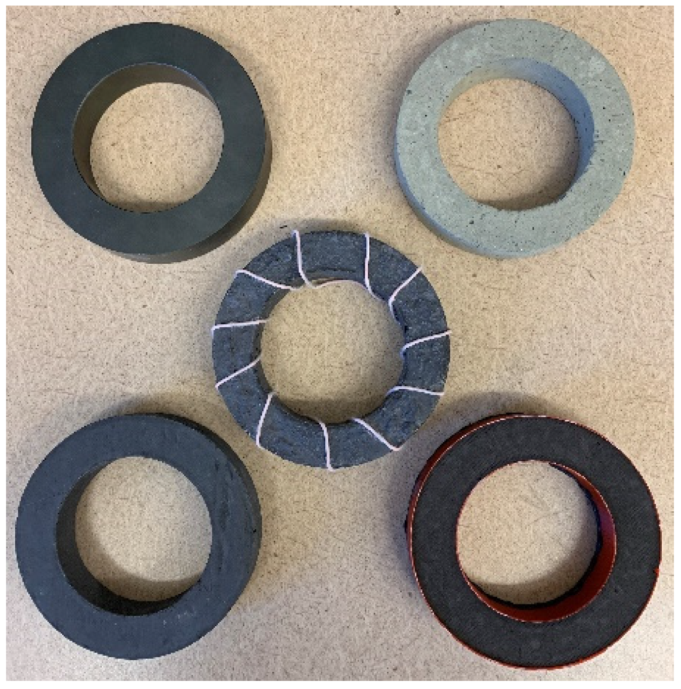
3.1. Magnetic Concrete Mix Design and Permeability Test

The primary objective of the current study is to examine how variations in the content of ferromagnetic materials—such as carbon steel fiber, ferrite powder (particle size 0.05 mm and magnetic permeability 2000 H/m), and ferrite chips—affect the magnetic permeability of the concrete and, in turn, influence magnetic field interactions within the IPT system.
For the experimental study, a series of specimens were fabricated, each differing in the composition of ferromagnetic materials. Carbon steel fiber, known for its high magnetic permeability and mechanical strength, was used to improve the magnetic properties of the concrete while also adding structural strength and integrity. Ferrite powder, widely used in magnetic applications due to its excellent magnetic properties and high relative permeability, was included to enhance magnetic field concentration within the concrete. Ferrite chips, similar in function to ferrite powder, were incorporated to further improve the magnetic properties of the concrete and ensure effective magnetic flux guidance toward the receiver coil. The specimens included varying percentages of these materials, as detailed in Table 1. The magnetic inclusions—carbon steel fiber, ferrite powder, and ferrite chips—are depicted in Figure 3.
Seven different specimen mixes, designated as S1 through S7, were tested to quantify the effects of varying concentrations and combinations of ferromagnetic materials on magnetic permeability. The mixing method uses a concrete bench mixer, and the specimens are allowed to cure for 28 days prior to demolding. To ensure uniform distribution of ferrite powder in the mix, the powder was applied to the concrete mix using hand spraying slowly. Table 1 summarizes the composition of each magnetic concrete specimen. For instance, S1 was designed for high strength (25% steel fiber) and low cost without ferrite material, while S2 aimed for higher strength and increased magnetic permeability by incorporating 12% ferrite powder and reducing carbon steel fiber to 12%. Other specimens, such as S4 and S5, were designed to determine which material contributes most to relative permeability, with S4 using 8% ferrite powder and no carbon steel fiber and S5 using 8% ferrite chips and no carbon steel fiber. Specimens S6 and S7 prioritized achieving the highest permeability by eliminating carbon steel fiber, albeit at the expense of structural strength.
Magnetic permeability tests were used to calculate the relative permeability ( μ r ) of each specimen. The relative permeability was calculated using the toroid inductance equation:
μ r = 2 π L μ 0 N 2 h ln b a  
where L represents the inductance measured using an LCR meter,  μ 0  is the permeability constant of free space, N = 10 is the total number of coil windings, h = 1.9 cm is the axial length of the toroidal core, and b = 10 cm and a = 6.5 cm are the outer and inner radii of the toroid, respectively. The toroid’s inherently closed magnetic circuit minimized external magnetic field interactions, ensuring precise and reliable measurements, as shown in Figure 4.

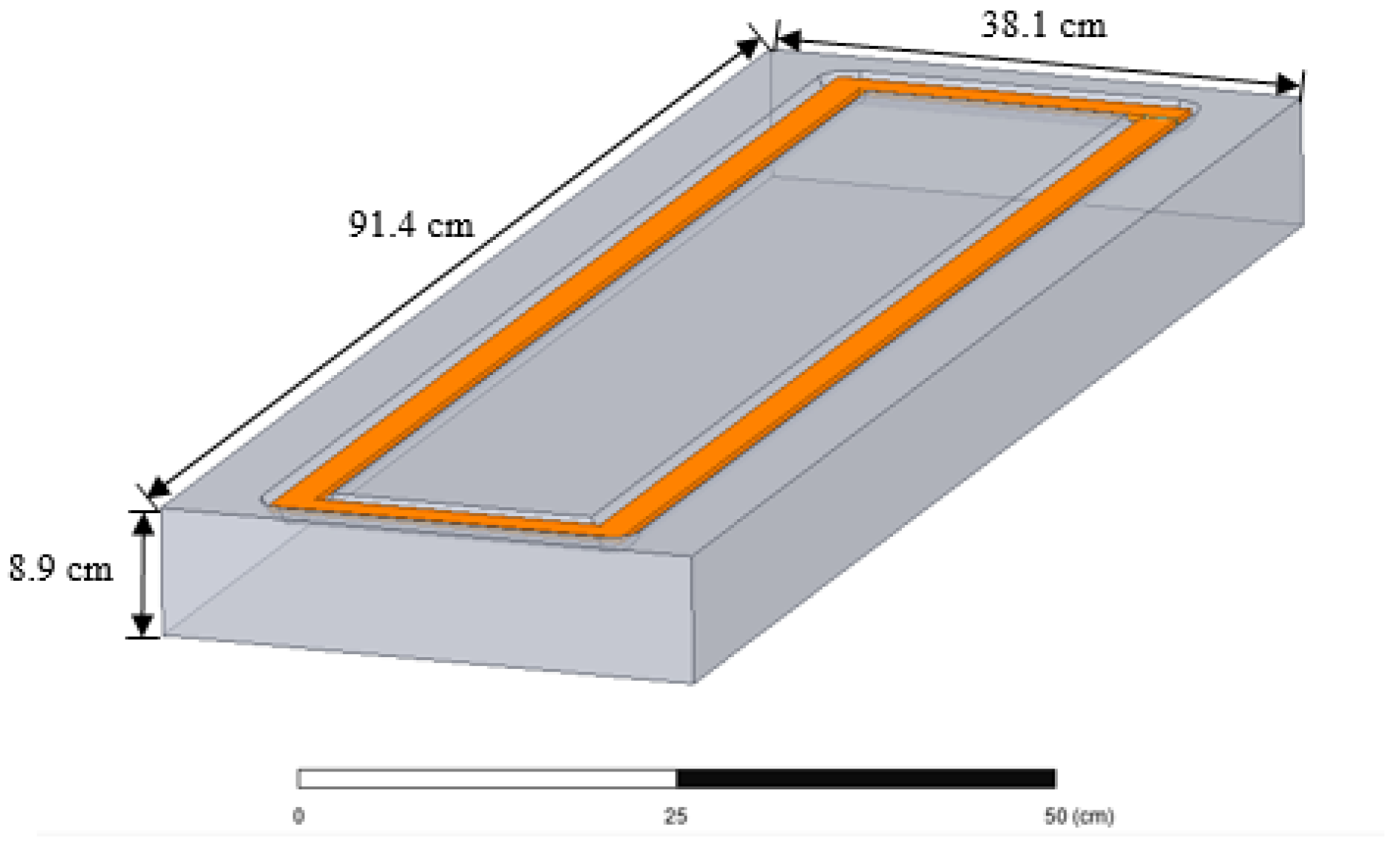
3.2. Transmitter Coupler Design with Magnetic Concrete

The design of an IPT system with an LCL-S (Single Capacitance–Double-Inductance Series)-compensated topology would have Litz wires supported on ferrite bars [2]. To replace the ferrite bars with magnetic concrete would require forming a slab, as shown in Figure 5. Both coupler designs were simulated under identical system conditions using an LCL-S-compensated IPT configuration. The geometrical configuration and operating frequency of the receiver coil were kept constant to ensure a fair comparison [2].
The design of the magnetic concrete slab is based on the dimensions of the ferrite bar coupler system and involves determining the required dimensions of the magnetic concrete slab to ensure the air space between the Litz coil and the receiver remain the same. Numerical models using ANSYS Maxwell (v.16) are then constructed to help visualize the potential magnetic flux propagation before finalizing the mix design. The magnetic concrete slab was fabricated with a slot specifically designed for the transmitter coil, as illustrated in Figure 5b. The dimensions of the magnetic concrete base used for the transmitter coil are shown in Figure 6. Both designs were tested with a consistent air gap of 12.7 cm between the transmitter and receiver coils, at an operating frequency of 85 kHz, and delivering an output power of 3 kW. The same magnetic core is used in both coupler designs 1 and 2.
The coupling coefficient (k) was calculated to evaluate magnetic coupling efficiency between the transmitter and receiver coils using the following equation:
k = M L 1 L 2
where M is the mutual inductance between the coils,  L 1  is the self-inductance of the transmitter coil, and  L 2  is the self-inductance of the receiver coil. This parameter allowed for a quantitative comparison of power transfer efficiency between the two designs, with higher k values indicating better coupling efficiency and more efficient power transfer.

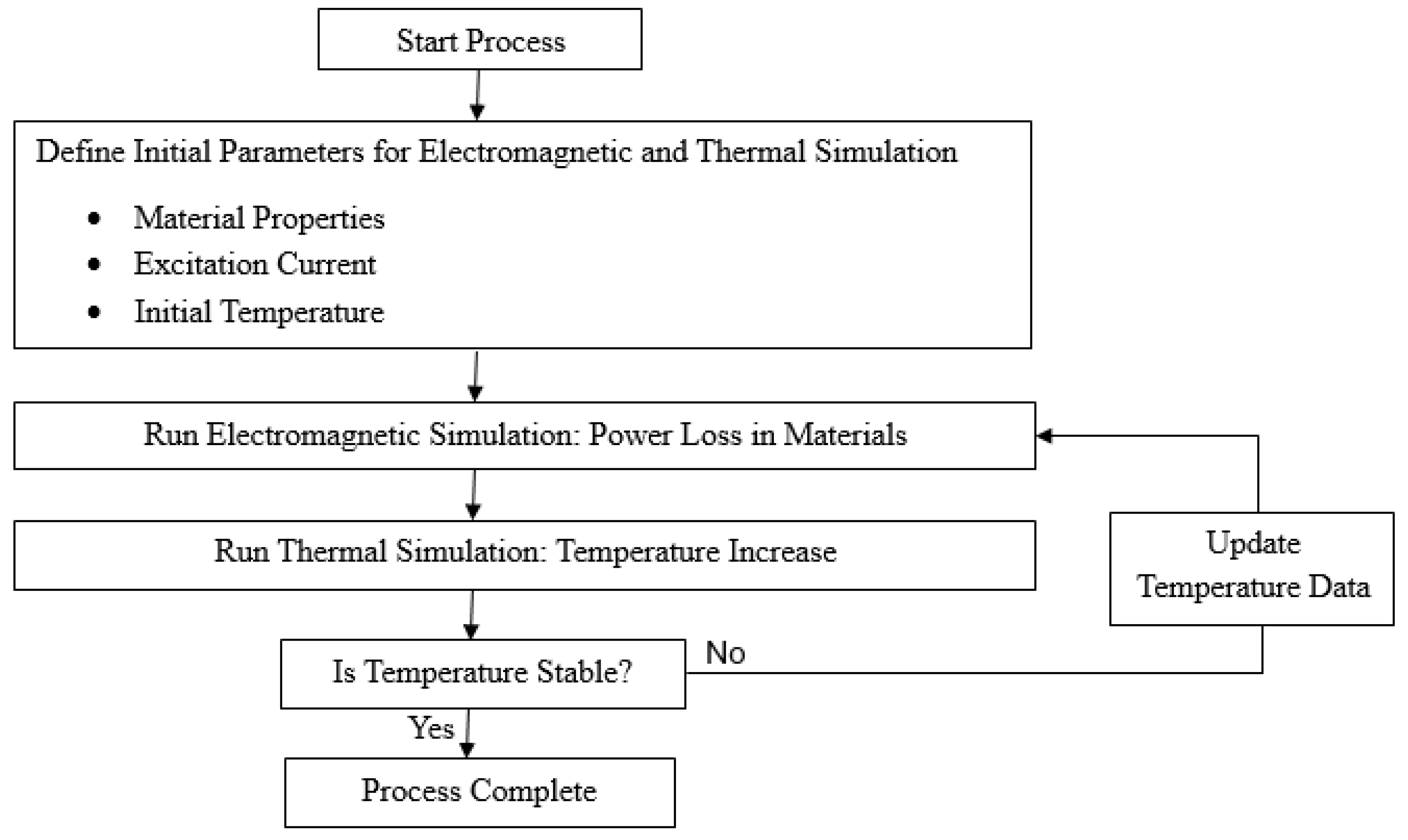
3.3. Electromagnetic–Thermal Simulation in IPT Systems

A coupled electromagnetic–thermal simulation model was developed to evaluate the heat generation and temperature distribution within the IPT system under 85 kHz operation. The electromagnetic analysis is based on Maxwell’s equations in the frequency domain, which describes how time-varying electric and magnetic fields propagate and interact with materials. The primary field quantities considered are the magnetic vector potential A and the electric scalar potential V. The governing equation for A in a lossy medium is derived from Ampère’s law and Faraday’s law, given by the following:
× H = J e + J i ,   × E = j ω B
where H is the magnetic field intensity, E is the electric field intensity, B is the magnetic flux density, Je is the excitation current density, and Ji is the induced current density.
We used the following constitutive relations:
B = μ H ,   J i = σ E
where  μ = μ 0 μ r  is the absolute magnetic permeability and  σ  is the electrical conductivity. A is defined as follows:
B = × A
Substituting into Faraday’s law gives the following:
E = j ω A V
Substituting Equations (4) and (6) into Ampere’s law results in the following:
× ( 1 μ × A ) + j ω σ A + σ V = J e
In time-harmonic eddy current simulations, the scalar potential gradient  V  is often neglected due to the use of the coulomb gauge or the assumption of low capacitive effects. This simplifies the formulation to the following:
× ( 1 μ × A ) + j ω σ A = J e
After solving for A, the magnetic flux density B and electric field E are calculated using Equations (5) and (6), respectively. The induced current density  J i  is then obtained from Equation (4), which defines the relationship  J i = σ E .
The volumetric Ohmic power loss Pohmic, which primarily occurs in conductive regions such as Litz wire, is calculated by the following:
P o h m i c = 1 2 J i 2 σ
Core losses in ferrite materials are modeled using an empirical Steinmetz-type expression:
P c o r e _ l o s s = C m f x B m y
where Pcore_loss is the volumetric core loss, Cm is a material-specific coefficient, Bm is the peak magnetic flux density, and x and y are empirical exponents. This model is applied only to ferrite cores, where Cm = 3.2 × 10⁻³, x = 1.46, and y = 2.75 [62].
The thermal analysis is performed by solving the steady-state heat conduction equation:
· k T + P t o t a l = 0
where k is the thermal conductivity, T is the temperature, and  P t o t a l  is the total volumetric heat generation applied as input to the thermal solver.
The simulation workflow, depicted in Figure 7, begins with defining the initial parameters, including material properties, excitation current, and initial temperature settings. The process consists of several key steps. First, system parameters are established—specifically, material properties such as thermal conductivity and magnetic permeability, along with the excitation current based on the system’s operating conditions. The thermal properties of each IPT component—including Litz wire, ferrite, magnetic concrete, and normal concrete—are summarized in Table 2. The initial temperature, typically representing the ambient or starting temperature, is also defined.
Next, an electromagnetic simulation is performed to calculate power losses within various system components, with a particular focus on materials such as Litz wire, ferrite cores, and magnetic concrete. These calculated losses are then applied as heat sources in the thermal simulation, which determines the resulting temperature distribution across the system. This process is iterative. Temperature input data are then updated, and simulations are rerun until thermal equilibrium is reached. It should be cautioned that the current study only considers the losses from the Litz wire, ferrite cores, and magnetic concrete. Additional losses from the power of electronics may also occur.
By incorporating magnetic concrete into these simulations, the model provides insights into heat distribution and potential thermal stresses, thereby supporting enhanced system design and optimized thermal management strategies.

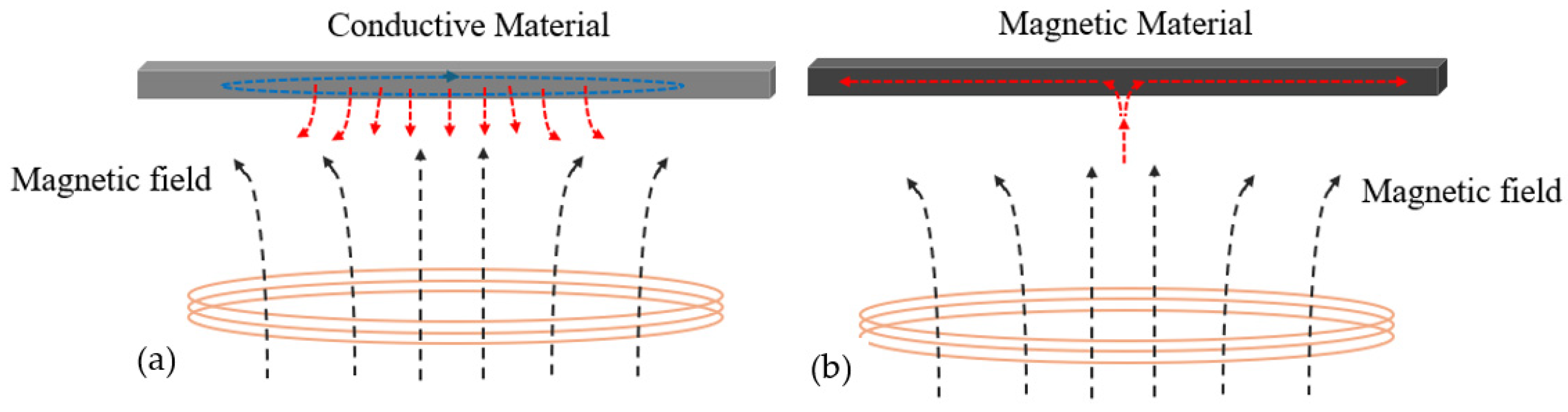
3.4. Shielding Potential Analysis in Magnetic Concrete-Based IPT Systems

Effective shielding is a critical component in IPT systems to minimize EMI and maintain the safety and reliability of railway operations. Passive shielding in IPT systems generally uses two primary methods: conductive materials and ferrite materials. Conductive materials, such as aluminum or copper, work by inducing eddy currents when exposed to a time-varying magnetic field. These eddy currents generate counter-magnetic fields that oppose the original magnetic field, reducing overall magnetic field penetration, as shown in Figure 8. Conductive shielding is lightweight and relatively easy to manufacture and implement; however, it can result in energy losses and heating due to the induced eddy currents.
Ferrite materials offer high magnetic permeability and are effective at absorbing and redirecting magnetic flux lines, providing substantial attenuation of magnetic fields, as depicted in Figure 8b. This method is particularly effective at suppressing high-frequency EMI with minimal energy loss. However, ferrite materials are brittle and can be mechanically challenging to handle and install, especially in large-scale applications. Using ferrite material to make magnetic concrete resulted in a composite that combines the high magnetic permeability of ferrites with the mechanical robustness of concrete, making it well-suited for large scale railway applications where mechanical durability and ease of installation are essential.
To study the shielding potential of magnetic concrete, the electromagnetic flux density distribution in two IPT system designs—one using traditional ferrite cores and the other incorporating a magnetic concrete slab—was analyzed using Ansys Maxwell software. The simulation setup involved several critical steps: First, 3D models of the IPT system were created, featuring couplers in two versions: one utilizing ferrite cores [2] and the other a magnetic concrete slab, as shown in Figure 6. The electromagnetic properties of the materials were defined, and appropriate boundary conditions were applied to simulate real-world operating environments, including the source current and operating frequency typical of railway applications.

4. Results and Discussion

4.1. Optimization of Magnetic Concrete Mix for IPT Systems

In terms of workability and cost considerations, the choice of ferrite chips versus ferrite powder was a significant factor. Although ferrite chips were initially considered, the high cost and difficulty of crushing ferrite bars into chip form led to the preference of ferrite powder: Ferrite powder is not only less costly but also easier to mix and was used as a replacement for the fine aggregate typically found in regular concrete mixes. The resulting magnetic concrete mix consisted of 33% ferrite powder by weight, ensuring an optimal balance of structural integrity and magnetic properties. The water-to-cement (w/c) ratio was maintained at 0.57 to achieve satisfactory workability while retaining adequate strength.
The inclusion of ferrite powder can complicate the water–cement ratio in the concrete mix, which is reflected in the reduction in concrete strength. Compression tests were conducted to confirm the structural viability of the magnetic concrete mix. The tests were performed using a Universal Testing Machine (UTM), as illustrated in Figure 9. The results presented in Table 3 and Table 4 show that the compressive strength of the magnetic concrete mix is comparable to that of standard concrete. This indicates that the inclusion of ferrite powder does not compromise the structural integrity of the magnetic concrete.
Figure 10 shows the reading and setup of a relative permeability test using an LCR meter. The relative permeability test results showed that specimen S7 exhibited a relative permeability of 18, as detailed in Table 1. This value underscores the effectiveness of magnetic concrete in enhancing magnetic field interactions within the IPT system. The measured relative permeability of 18 for the magnetic concrete was subsequently applied in Ansys Maxwell for comparative analyses of transmitter coupler designs in IPT systems.
The current study involves making full-scale transmitter couplers utilizing different materials—including normal concrete, magnetic concrete, and W-I shaped designs—that were constructed and tested for power efficiency at 3 kW, as shown in Figure 11. Table 5 shoes the measured system parameters for the full-scale power transmitter.

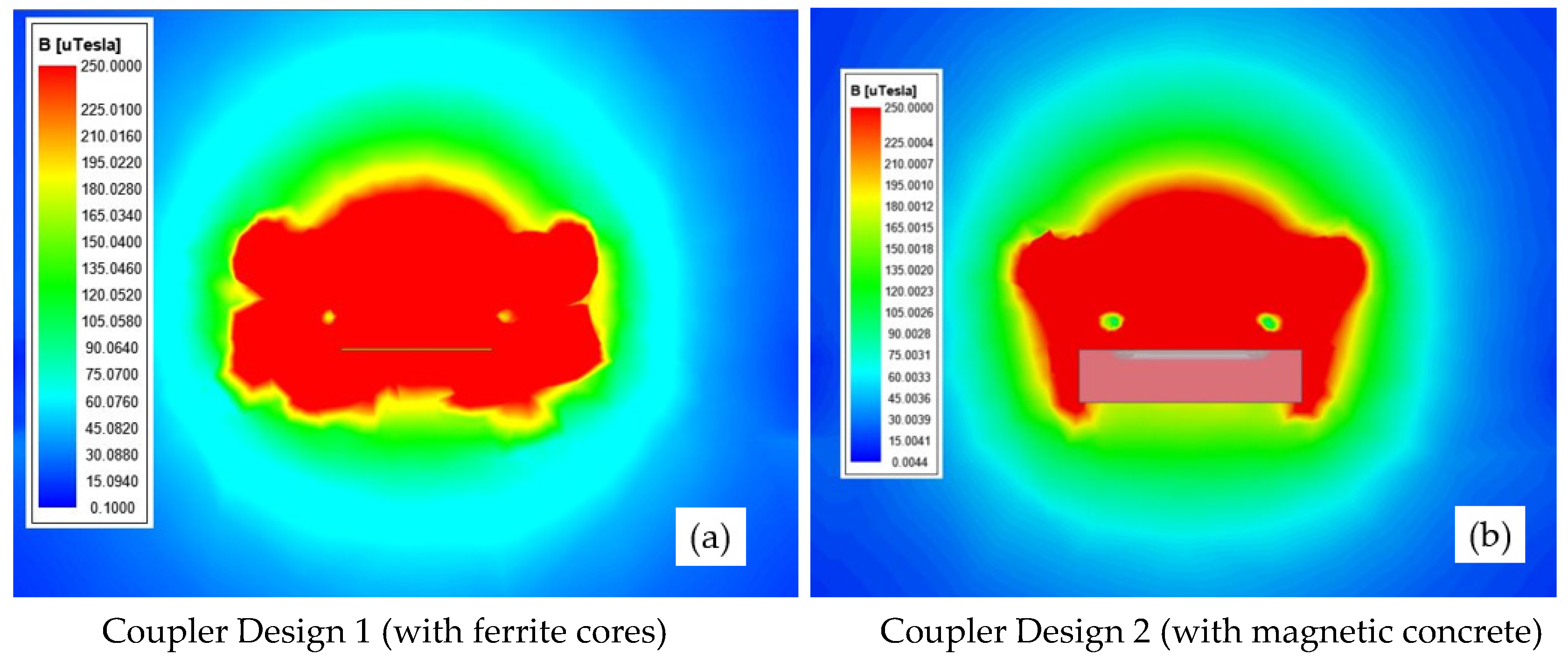
4.2. Comparative Analysis of Transmitter Coupler Designs in IPT Systems

This section primarily focuses on evaluating changes in the coupling coefficient between Coupler Design 1 (using W-I ferrite cores) and Coupler Design 2 (utilizing magnetic concrete). As shown in Table 6, the simulation results from Ansys Maxwell reveal a slight decrease in the coupling coefficient from 0.236 for W-I ferrite cores to 0.232 for magnetic concrete. Additionally, Table 6 indicates a corresponding simulation-based power efficiency of 90.85% for W-I ferrite cores and 89.71% for magnetic concrete, with normal concrete significantly lower at 84.3%. The experimental validation conducted in a full-scale setting, as presented in Table 7, demonstrates a slight efficiency drop from 89.17% for W-I ferrite cores to 88.12% for magnetic concrete. These comprehensive evaluations confirm magnetic concrete’s capability to maintain effective magnetic coupling and energy efficiency comparable to traditional ferrite cores, thereby validating its potential as a suitable alternative material in IPT systems.
The change in coupling coefficient correlates with overall system efficiency. In high-power applications such as railway systems, efficiency losses at elevated power levels can significantly impact performance and energy consumption. By enhancing power transfer efficiency, magnetic concrete helps to keep high power transfer while minimizing energy losses, making it an attractive material for IPT system designs. These findings suggest that magnetic concrete is a viable alternative to ferrite cores in the development of transmitter couplers for IPT systems. Its robustness, cost-effectiveness, and efficiency improvements are particularly advantageous in environments where durability and economic feasibility are critical.

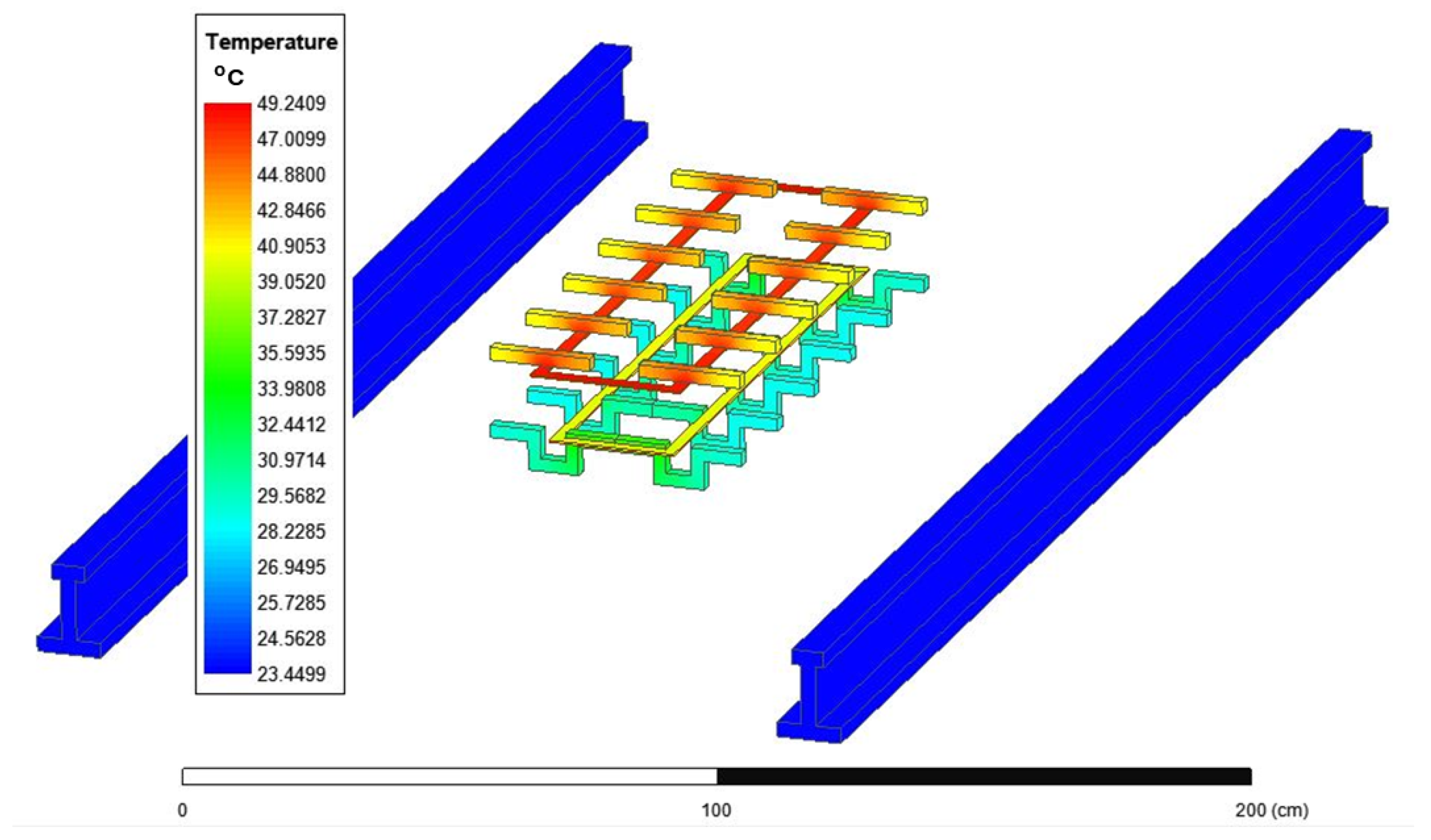
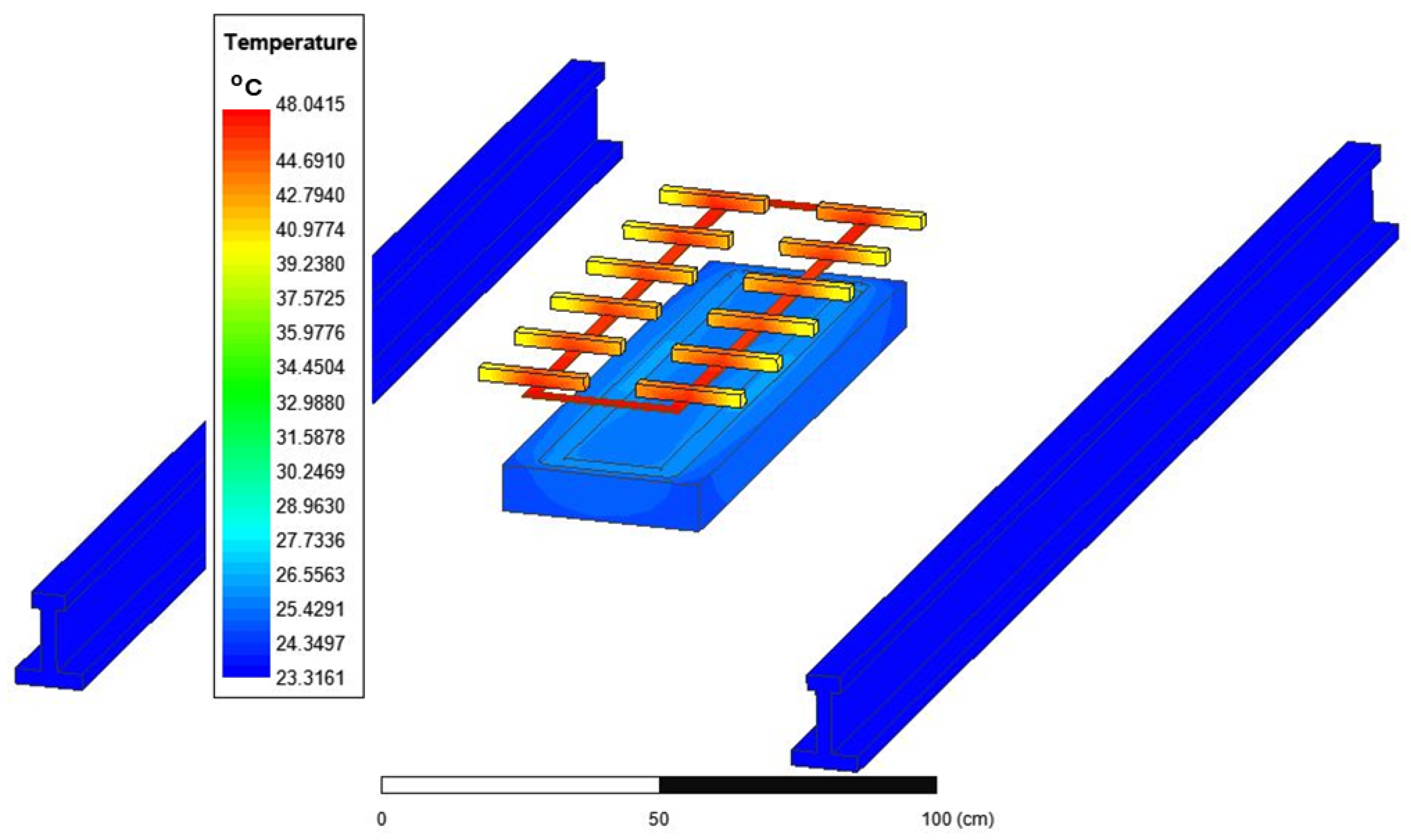
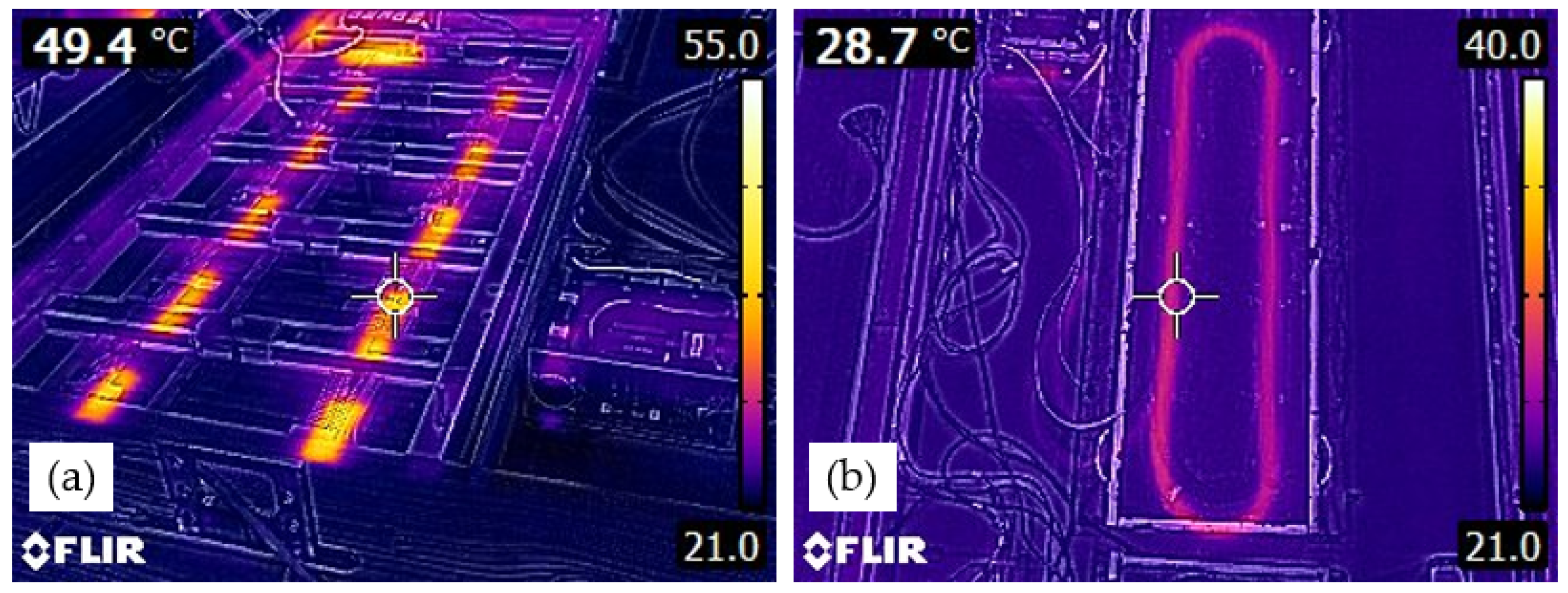
4.3. Thermal Analysis in IPT Systems

The thermal analysis of the IPT systems, conducted using the Ansys simulation package, evaluates the thermal behavior of various coupler designs to ensure efficient system operation under diverse conditions while maintaining thermal stability and performance integrity. The temperature distribution for the coupler design with ferrite bars (referred to as Coupler Design 1) is presented in Figure 12. The color-coded scale illustrates temperature variations, with red indicating the highest temperatures and blue representing the lowest. The thermal simulation of this design provides a detailed temperature profile across the coupler, closely aligning with experimental tests conducted on the current design, thereby confirming the accuracy and reliability of the Ansys simulation package for thermal analysis in IPT systems.
This study also explores the temperature distributions for the coupler design with magnetic concrete (Coupler Design 2) and a design utilizing normal concrete (Coupler Design 3), as shown in Figure 13 and Figure 14, respectively. These simulations were performed under identical operating conditions, including a 12.7 cm air gap between the transmitter and receiver coils, a frequency of 85 kHz, and an output power of 3 kW. The analysis highlights localized hotspots, particularly in areas with high magnetic flux density. Notably, the inclusion of magnetic concrete in Coupler Design 2 demonstrates improved thermal behavior, with a more uniform temperature distribution compared to the ferrite and normal concrete designs. This improvement is attributed to the enhanced thermal conductivity and magnetic properties of magnetic concrete.
The results for Coupler Design 3 (Figure 14) reveal increased localized heating and less efficient heat dissipation, which may lead to higher thermal stress and material degradation. These findings underscore the limitations of standard concrete as a coupler material in high-power IPT systems and highlight the advantages of magnetic concrete in addressing these challenges.
Due to the amount of ferrite powder added to the magnetic concrete, the influence on temperature increase is less significant when compared to the electromagnetic effects. This is evident when comparing Figure 13 and Figure 14, where the maximum temperature increases due to magnetic concrete comprising less than 0.3%.
The incorporation of magnetic concrete into IPT systems is expected to provide a more uniform temperature distribution and reduced hotspots due to its higher thermal conductivity and magnetic properties. Experimental thermal imaging further validates these findings, as shown in Figure 15. The thermal images show the actual temperature distribution across the system during operation, highlighting the lower temperatures and more evenly distributed heat in the transmitter coil employing magnetic concrete.
Even though no quantitative assessment has been performed on the full-size IPT transmitters, the findings of this study, nonetheless, validate the feasibility of magnetic concrete as a material for high-power wireless power transfer applications. The thermal analysis also demonstrates its potential to improve thermal performance, contributing to the development of robust and efficient railway power systems.

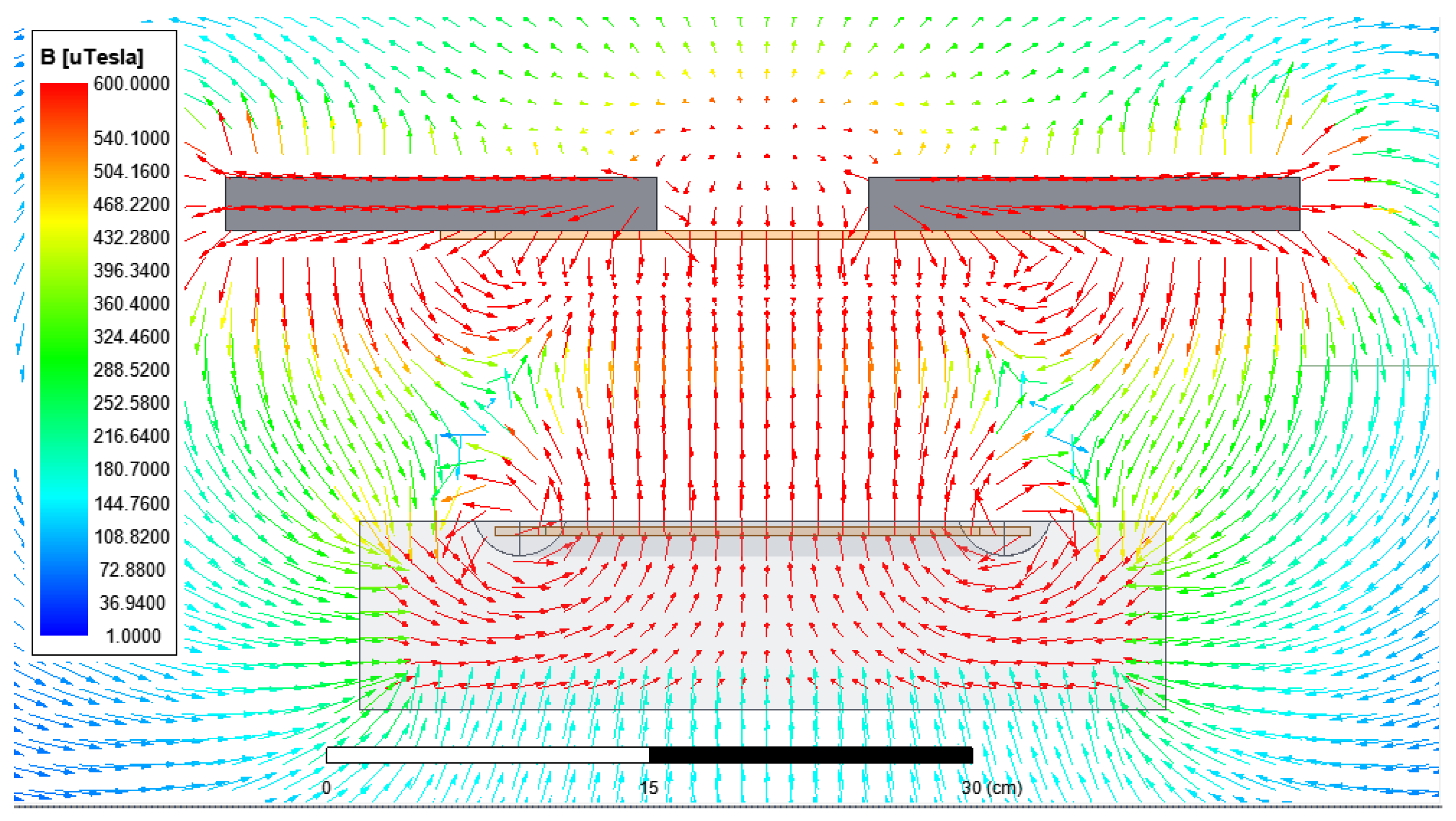
4.4. Shielding Analysis of IPT Systems

This section presents the results of the shielding effectiveness of two coupler designs: one using traditional ferrite cores and the other using a magnetic concrete slab. The simulations were conducted using Ansys Maxwell.
Figure 16a shows the magnetic field distribution in the W-I ferrite core design (Coupler Design 1). The color-coded magnetic flux density (B-field) is represented in the unit of micro-Tesla (µT). The denser and closely spaced field lines indicate stronger magnetic fields, primarily concentrated around the ferrite cores. This visualization highlights the effective magnetic flux concentration achieved by ferrite materials, demonstrating their high magnetic permeability and efficiency in guiding magnetic fields.
In contrast, Figure 16b shows the magnetic field distribution in Coupler Design 2, which utilizes a magnetic concrete slab. Magnetic concrete guides the magnetic flux efficiently, reducing the magnetic flux density on the ground. This reduced distribution of magnetic fields indicates a more uniform flux distribution, which is beneficial for protecting various sensors installed along the railway tracks, such as condition monitoring, acceleration, temperature, and rotation rate sensors. The magnetic concrete design shows an ability to guide the magnetic flux away from the ground and critical areas, reducing electromagnetic interference and enhancing the overall safety of the railway system.
Figure 17 provides a cross-sectional visualization of the magnetic field flux for the IPT system with a magnetic concrete slab. The color-coded streamlines represent the magnetic flux density in the system. Regions with denser and closely spaced field lines indicate stronger magnetic fields. Notably, the red lines highlight areas with higher magnetic flux density, primarily concentrated around the coil within the magnetic concrete slab. This simulation reveals how the magnetic concrete slab influences the magnetic flux lines, demonstrating its effectiveness in guiding the magnetic field. The magnetic concrete’s ability to concentrate the magnetic flux within the desired paths enhances the efficiency of power transfer and reduces unwanted magnetic field leakage.
The simulations confirm that the magnetic concrete slab not only enhances the durability and structural integrity of the IPT system but also provides effective shielding comparable to or better than that of traditional ferrite cores. The relative shielding efficiency computed for the magnetic concrete is about 51.5% for the closest region near the two railroad tracks. From our prior studies, W-I coupler systems have met the threshold of the electromagnetic field effect for human safety [30]. The current magnetic concrete-based coupler system also met the requirements. The ferrite cores in Coupler Design 1 offer high magnetic permeability and effective shielding but are fragile and can degrade over time, especially in dynamic railway environments. In contrast, Coupler Design 2 with a magnetic concrete slab shows a significant ability to guide magnetic flux efficiently, reducing the magnetic flux density on the ground. This reduction in flux density is advantageous for safeguarding sensors along the railway tracks, ensuring the reliability and safety of railway operations.
As described by several studies [3,21,31,64], the IPT system improves the aesthetics, safety, and costs for short-distance transits such as light rails, street cars, and trams. The current study further demonstrates that the findings from these simulations are instrumental in validating the theoretical benefits of using magnetic concrete slabs in IPT systems. The enhanced shielding capabilities, coupled with improved durability and efficiency, support the potential of magnetic concrete as an alternative to traditional ferrite cores.

5. Conclusions

To encourage rail transportation electrification using battery locomotives, the IPT system that enables wireless power transfer is a transformative technology that can enhance rail safety and efficiency. The incorporation of magnetic concrete into IPT systems provides a promising replacement for ferrite bars in coil supports. This paper provides a comprehensive study of the design of magnetic concrete considering the magnetic permeability, coupling efficiency, and thermal field effects. This paper also investigates the shielding potential of magnetic concrete-based IPT systems. The results of this study are expected to improve wireless power transfer technologies and establish magnetic concrete as a solution for energy transmission in railway applications.
Through experimental testing and numerical modeling, an optimal magnetic concrete mix comprising 33% ferrite powder by weight and a water-to-cement ratio of 0.57 was developed. This formulation achieved a critical balance between workability, cost-effectiveness, structural integrity, and magnetic performance. Compressive strength tests demonstrated structural compatibility with traditional concrete, confirming its suitability for railway infrastructure.
Comparative analyses of transmitter coupler designs using Ansys Maxwell simulations and experimental validations revealed that magnetic concrete closely matches the coupling efficiency of traditional W-I ferrite cores. Although magnetic concrete exhibits a marginal decrease in the coupling coefficient and power transfer efficiency, its substantial advantages, such as enhanced mechanical durability and significant cost reductions, present a compelling case for its practical deployment in IPT systems.
Predictive thermal analyses indicate superior thermal performance for magnetic concrete couplers, characterized by a more uniform temperature distribution and reduced hotspots. These findings were further validated by experimental thermal imaging, highlighting the material’s effectiveness in managing thermal stresses and enhancing operational stability in high-power applications.
Shielding analyses further support the efficacy of magnetic concrete, showcasing its ability to effectively guide magnetic flux and reduce electromagnetic interference, thereby safeguarding critical sensors and enhancing system safety. Compared to traditional ferrite cores, magnetic concrete not only provides comparable or improved shielding effectiveness but also overcomes limitations related to fragility and mechanical degradation.
Overall, this study validates magnetic concrete as a viable, robust, cost-effective, and efficient alternative to conventional ferrite cores in IPT systems. The integration of magnetic concrete into railway applications promises significant advancements in performance, durability, safety, and economic viability, representing an important innovation in infrastructure technology for wireless power transfer.
It is important to recognize that the current study started with the coil design, which predetermined the transfer frequency, and hence, the sensitivity of the magnetic properties of the magnetic concrete to frequency has not been investigated. Future studies will consider frequency change effects.
Future studies will also include the optimization of the magnetic concrete mix design and the evaluation of the long-term performance (fatigue, durability, aging, etc.) of magnetic concrete-based IPT systems in field conditions.

Author Contributions

Conceptualization, S.-E.C., K.L., T.Z., N.L.B. and X.S.; methodology, T.Z., S.-E.C., K.L. and X.S.; validation, K.L. and S.-E.C.; formal analysis, K.L., T.Z. and X.S.; investigation, S.-E.C., N.L.B. and L.H.; resources, T.Z., S.-E.C. and N.L.B.; data curation, K.L.; writing—original draft preparation, K.L., S.-E.C., T.Z., N.L.B. and L.H.; visualization, K.L. and S.-E.C.; supervision, T.Z., S.-E.C. and N.L.B.; project administration, T.Z.; funding acquisition, T.Z., N.L.B. and S.-E.C. All authors have read and agreed to the published version of the manuscript.

Funding

This research was funded by the Federal Railroad Association (FRA grant number: 693JJ621C000002).

Institutional Review Board Statement

Not applicable for studies not involving humans or animals.

Informed Consent Statement

Not applicable.

Data Availability Statement

The original contributions presented in this study are included in the article. Further inquiries can be directed to the corresponding author.

Acknowledgments

The authors would like to acknowledge the project advisor Omar Terek for his support. The contents of this paper reflect the views of the authors and not necessarily the views of the university. The authors are responsible for the facts and the accuracy of the data presented herein. The contents do not necessarily reflect the official views or policies of either the Federal Railroad Administration or US Department of Transportation.

Conflicts of Interest

Author Lynn Harris was employed by the company Deutsche Bahn. The remaining authors declare that the research was conducted in the absence of any commercial or financial relationships that could be construed as a potential conflict of interest.

References

  1. Wang, L.; Zhao, T.; Chen, S.; Cook, D. An Inductive Power Transfer System Design for Rail Applications. In Proceedings of the IEEE Transportation Electrification Conference and Expo (ITEC), Long Beach, CA, USA, 13–15 June 2018; pp. 84–89. [Google Scholar]
  2. Xu, X.; Wang, L.; Lin, K.; Zhao, T.; Chen, S.; Cook, D.; Ward, D. Design Considerations of an Inductive Power Transfer System for Rail Application. In Proceedings of the 2021 IEEE Transportation Electrification Conference and Expo (ITEC), Chicago, IL, USA, 21–25 June 2021; pp. 457–461. [Google Scholar]
  3. Kim, J.H.; Lee, J.; Park, H.S.; Choi, J.H.; Lee, S.Y. Development of 1-MW Inductive Power Transfer System for a High-Speed Train. IEEE Trans. Ind. Electron. 2015, 62, 6242–6250. [Google Scholar] [CrossRef]
  4. Sun, X.; Xu, X.; Lin, K.; Chen, S.-E.; Zhao, T. Static and Dynamic Analysis of Wireless Power Transfer for Battery-Electric Locomotives. In Proceedings of the 2024 IEEE Transportation Electrification Conference and Expo (ITEC), Chicago, IL, USA, 19–21 June 2024; pp. 1–6. [Google Scholar]
  5. Li, Y.; Zhang, X.; Zhao, T.; Wang, L.; Cook, D. Design and Implementation of a Novel WPT System for Railway Applications. In Proceedings of the 2017 IEEE PELS Workshop on Emerging Technologies: Wireless Power Transfer (WoW), Chongqing, China, 20–22 May 2017; pp. 213–216. [Google Scholar]
  6. Brecher, A.; Arthur, D. Review and Evaluation of Wireless Power Transfer (WPT) for Electric Transit Applications. Hum. Factors 2014, 49, 832–841. [Google Scholar]
  7. Lee, G.; Kim, M.Y.; Lee, S.-G.; Kim, J.H. Operational Verification of Semidynamic Wireless Power Transfer in Light-Rail Transit Systems. IEEE Trans. Transp. Electr. 2025, 11, 348–358. [Google Scholar] [CrossRef]
  8. Shi, L.; Yin, Z.; Jiang, L.; Li, Y. Advances in Inductively Coupled Power Transfer Technology for Rail Transit. CES Trans. Electr. Mach. Syst. 2017, 1, 383–396. [Google Scholar] [CrossRef]
  9. Thai, V.X.; Choi, S.Y.; Choi, B.H.; Kim, J.H.; Rim, C.T. Coreless Power Supply Rails Compatible with Both Stationary and Dynamic Charging of Electric Vehicles. In Proceedings of the 2015 IEEE 2nd International Future Energy Electronics Conference (IFEEC), Taipei, Taiwan, 1–4 November 2015; pp. 1–5. [Google Scholar]
  10. Inoue, R.; Nagasaki, Y.; Tsuda, M.; Miyagi, D. Basic Coil Structure for Rapid Charge in a Low-Frequency and High-Efficiency Wireless Power Transmission System Using High-Temperature Superconducting Coil for Railway Vehicle. IEEE Trans. Appl. Supercond. 2023, 33, 5500109. [Google Scholar] [CrossRef]
  11. Inoue, R.; Igarashi, K.; Nagasaki, Y.; Miyagi, D.; Tsuda, M.; Matsuki, H. Electric Power Transmission Characteristics of a Wireless Power Transmission System Using High-Temperature Superconducting Coils for Railway Vehicle. IEEE Trans. Appl. Supercond. 2019, 29, 5402305. [Google Scholar] [CrossRef]
  12. Inoue, R.; Ueda, H.; Kim, S. Study on Low-Loss and High-Energy Density Coil Structure of a Wireless Power Transmission System Using High-Temperature Superconducting Coils for Railway Vehicle. IEEE Trans. Appl. Supercond. 2022, 32, 4604704. [Google Scholar] [CrossRef]
  13. Wang, Y.; Lin, F.; Yang, S.; Cai, P.; Igarashi, S. Efficiency Optimization of Wireless Power Transfer System with Traction Motor Load for Modern Tram. In Proceedings of the 2018 IEEE PELS Workshop on Emerging Technologies: Wireless Power Transfer (WoW), London, UK, 2–5 July 2018; pp. 1–5. [Google Scholar]
  14. Jin, R.; Yang, Z.; Lin, F. Mutual Inductance Identification and Maximum Efficiency Control of Wireless Power Transfer System for the Modern Tram. In Proceedings of the 2017 IEEE PELS Workshop on Emerging Technologies: Wireless Power Transfer (WoW), London, UK, 3–6 July 2017; pp. 70–74. [Google Scholar]
  15. Hua, C.; Bin, C.; Zhihua, Z.; Yanqing, Z. Characteristics Analyses of Wireless Power Transfer for Ultra-High Speed Maglev Train. In Proceedings of the 2021 13th International Symposium on Linear Drives for Industry Applications (LDIA), Wuhan, China, 16–19 August 2021; pp. 1–5. [Google Scholar]
  16. Chung, Y.D.; Park, E.Y.; Lee, C.Y. Effect Analysis of Improving Transfer Efficiency for Inserted Resonance Patterns in Wireless Power Charging System of High-Speed Magnetic Levitation Train. In Proceedings of the 2018 21st International Conference on Electrical Machines and Systems (ICEMS), Jeju, Republic of Korea, 7–10 October 2018; pp. 903–907. [Google Scholar]
  17. Yuyu, G.; Zhongping, Y.; Xuejun, Z.; Zhiyong, Z. Analysis of the Effect of the Shielding on Coils in the Wireless Power Transfer System Applied in Trams. In Proceedings of the 2018 IEEE PELS Workshop on Emerging Technologies: Wireless Power Transfer (WoW), London, UK, 2–5 July 2018; pp. 1–6. [Google Scholar]
  18. Lee, G.; Kim, M.Y.; Lee, S.G.; Kim, J.H. Effect of Wireless Power Transfer on Track Circuit. J. Korean Soc. Railw. 2022, 25, 725–732. [Google Scholar] [CrossRef]
  19. Lee, S.-H.; Kim, M.-Y.; Lee, B.-S.; Lee, J. Impact of Rebar and Concrete on Power Dissipation of Wireless Power Transfer Systems. IEEE Trans. Ind. Electron. 2020, 67, 276–287. [Google Scholar] [CrossRef]
  20. Song, B.; Dong, S.; Gao, X.; Li, Y.; Cui, S. A Tripolar Wireless Power Transfer System with Low Leakage Magnetic Field for Railway Vehicles. In Proceedings of the 2019 21st European Conference on Power Electronics and Applications (EPE ’19 ECCE Europe), Genova, Italy, 2–6 September 2019; pp. P.1–P.7. [Google Scholar]
  21. Lee, S.-H.; Kim, J.-H.; Lee, J.-H. Development of a 60 kHz, 180 kW, Over 85% Efficiency Inductive Power Transfer System for a Tram. Energies 2016, 9, 1075. [Google Scholar] [CrossRef]
  22. Ukita, K.; Nakamura, T.; Yamada, Y.; Hayashi, T.; Yoshino, H. Evaluation of a Non-Contact Power Supply System with a Figure-of-Eight Coil for Railway Vehicles. In Proceedings of the 2015 IEEE PELS Workshop on Emerging Technologies: Wireless Power (WoW), Daejeon, Republic of Korea, 5–8 June 2015; pp. 1–5. [Google Scholar]
  23. Zhou, Q.; Shi, H. New-Type Tramcars and Their Power Supply Mode. Urban Rapid Rail Transit 2008, 21, 95–97. [Google Scholar]
  24. Covic, G.A.; Boys, J.T. Modern Trends in Inductive Power Transfer for Transportation Applications. IEEE J. Emerg. Sel. Top. Power Electron. 2013, 1, 28–41. [Google Scholar] [CrossRef]
  25. Hu, P.; Wang, H.; Zhang, C.; Hua, L.; Tian, G. Wheel–Rail Contact-Induced Impact Vibration Analysis for Switch Rails Based on the VMD-SS Method. Sensors 2022, 22, 6872. [Google Scholar] [CrossRef]
  26. Wang, D.; Zhang, J.; Cui, S.; Bie, Z.; Song, K.; Zhu, C.; Matveevich, M.I. Modern Advances in Magnetic Materials of Wireless Power Transfer Systems: A Review and New Perspectives. Nanomaterials 2022, 12, 3662. [Google Scholar] [CrossRef]
  27. Katagiri, Y.; Bu, Y.; Mizuno, T.; Sato, M. Efficiency Improvement in Dynamic Wireless Power Transfer by Placing a Magnetic Sheet Under the Power Transmitting Coil. IEEE Access 2025, 13, 22956–22963. [Google Scholar] [CrossRef]
  28. Liang, C.; Wang, L.; Zhou, J.; Xu, Z.; Chen, Y. Modeling and Analysis of Thermal Characteristics of Magnetic Coupler for Wireless Electric Vehicle Charging System. IEEE Access 2020, 8, 173177–173185. [Google Scholar] [CrossRef]
  29. Rasekh, N.; Dabiri, S.; Rasekh, N.; Mirsalim, M.; Bahiraei, M. Thermal Analysis and Electromagnetic Characteristics of Three Single-Sided Flux Pads for Wireless Power Transfer. J. Clean. Prod. 2020, 243, 118561. [Google Scholar] [CrossRef]
  30. Lin, K.; Xu, X.; Zhao, T.; Chen, S.; Braxtan, N.; Cook, D.; Ward, D. Passive Shielding Design of an Inductive Power Transfer System for Railway Applications. In Proceedings of the 2022 IEEE Transportation Electrification Conference and Expo (ITEC), Anaheim, CA, USA, 15–17 June 2022; pp. 606–610. [Google Scholar]
  31. Lee, G.; Kim, M.Y.; Lee, C.; Jang, D.; Lee, B.S.; Kim, J.H. Electromagnetic Field Tests of a 1-MW Wireless Power Transfer System for Light Rail Transit. Energies 2021, 14, 1171. [Google Scholar] [CrossRef]
  32. Lee, S.B.; Ahn, S.; Jang, I.G. Simulation-Based Feasibility Study on the Wireless Charging Railway System with a Ferriteless Primary Module. IEEE Trans. Veh. Technol. 2017, 66, 1004–1010. [Google Scholar] [CrossRef]
  33. Sun, T.; Xie, X.; Wang, Z. Design Challenges of the Wireless Power Transfer for Medical Microsystems. In Proceedings of the 2013 IEEE International Wireless Symposium (IWS), Beijing, China, 14–18 April 2013; pp. 1–4. [Google Scholar]
  34. Alsayegh, M.; Saifo, M.; Clemens, M.; Schmuelling, B. Magnetic and Thermal Coupled Field Analysis of Wireless Charging Systems for Electric Vehicles. IEEE Trans. Magn. 2019, 55, 7400704. [Google Scholar]
  35. Niu, S.; Yu, H.; Niu, S.; Jian, L. Power Loss Analysis and Thermal Assessment on Wireless Electric Vehicle Charging Technology: The Over-Temperature Risk of Ground Assembly Needs Attention. Appl. Energy 2020, 275, 115344. [Google Scholar] [CrossRef]
  36. Lee, C.; Woo, S.; Shin, Y.; Rhee, J.; Moon, J.; Ahn, S. EMI Reduction Method for Wireless Power Transfer Systems with High Power Transfer Efficiency Using Frequency Split Phenomena. IEEE Trans. Electromagn. Compat. 2022, 64, 1683–1693. [Google Scholar] [CrossRef]
  37. Edwards, K.A.T.; Al-Abed, S.H.; Hosseini, S.; Brake, N.A. Properties of a Magnetic Concrete Core Transformer for Application in Wireless Power Transfer Systems. Constr. Build. Mater. 2019, 227, 117041. [Google Scholar] [CrossRef]
  38. Tavakoli, R.; Zhang, X.; Xu, X.; Zhao, T.; Wang, L.; Cook, D. Magnetizable Concrete Composite Materials for Road-Embedded Wireless Power Transfer Pads. In Proceedings of the 2017 IEEE Energy Conversion Congress and Exposition (ECCE), Cincinnati, OH, USA, 1–5 October 2017; pp. 4041–4048. [Google Scholar]
  39. Carretero, C.; Lope, I.; Acero, J. Magnetizable Concrete Flux Concentrators for Wireless Inductive Power Transfer Applications. IEEE J. Emerg. Sel. Top. Power Electron. 2020, 8, 2696–2706. [Google Scholar] [CrossRef]
  40. Sun, X.; Lin, K.; Zhou, J.; Chen, S.-E.; Braxtan, N.; Zhao, T. Optimizing Magnetic Block Structure for Enhanced Coupling Coefficients in Wireless Power Transfer: A Finite Element Analysis Approach. In Proceedings of the 2024 IEEE Transportation Electrification Conference and Expo (ITEC), Chicago, IL, USA, 19–21 June 2024; pp. 1–6. [Google Scholar]
  41. Mohammad, M.; Onar, O.C.; Pries, J.L.; Galigekere, V.P.; Su, G.-J.; Wilkins, J. Thermal Analysis of a 50 kW Three-Phase Wireless Charging System. In Proceedings of the 2021 IEEE Transportation Electrification Conference and Expo (ITEC), Chicago, IL, USA, 21–25 June 2021; pp. 1–6. [Google Scholar]
  42. Zhang, B.; Deng, J.; Li, L.; Wang, Z.; Wang, S.; Guidi, G. Thermal Analysis and Design of a 30 kW EV Wireless Charger with Liquid-Cooled Shell for Magnetic Coupler and Integrated Power Converter. In Proceedings of the 2021 IEEE Applied Power Electronics Conference and Exposition (APEC), Phoenix, AZ, USA, 14–18 June 2021; pp. 426–431. [Google Scholar]
  43. Kindl, V.; Pechanek, R.; Zavrel, M.; Kavalir, T.; Turjanica, P. Inductive Coupling System for Electric Scooter Wireless Charging: Electromagnetic Design and Thermal Analysis. Electr. Eng. 2020, 102, 3–12. [Google Scholar] [CrossRef]
  44. Mohammad, M.; Onar, O.C.; Galigekere, V.P.; Su, G.-J.; Wilkins, J. Thermal Design and Optimization of High-Power Wireless Charging System. In Proceedings of the 2022 IEEE Applied Power Electronics Conference and Exposition (APEC), Houston, TX, USA, 20–24 March 2022; pp. 480–485. [Google Scholar]
  45. Kim, J.; Kim, H.; Song, C.; Kim, I.-M.; Kim, Y.-I.; Kim, J. Electromagnetic Interference and Radiation from Wireless Power Transfer Systems. In Proceedings of the 2014 IEEE International Symposium on Electromagnetic Compatibility (EMC), Raleigh, NC, USA, 4–8 August 2014; pp. 171–176. [Google Scholar]
  46. Kadem, K.; Le Bihan, Y.; Bensetti, M.; Laboure, É.; Diet, A.; Debbou, M. Reduction of the Shielding Effect on the Coupling Factor of an EV WPT System. In Proceedings of the 2019 IEEE PELS Workshop on Emerging Technologies: Wireless Power Transfer (WoW), London, UK, 5–8 June 2019; pp. 21–24. [Google Scholar]
  47. Kim, H.; Cho, J.; Ahn, S.; Kim, J.; Kim, J. Suppression of Leakage Magnetic Field from a Wireless Power Transfer System Using Ferrimagnetic Material and Metallic Shielding. In Proceedings of the 2012 IEEE International Symposium on Electromagnetic Compatibility, Pittsburgh, PA, USA, 5–10 August 2012; pp. 640–645. [Google Scholar]
  48. Besnoff, J.; Chabalko, M.; Ricketts, D.S. A Frequency-Selective Zero-Permeability Metamaterial Shield for Reduction of Near-Field Electromagnetic Energy. IEEE Antennas Wirel. Propag. Lett. 2016, 15, 654–657. [Google Scholar] [CrossRef]
  49. Park, H.H.; Kwon, J.H.; Kwak, S.I.; Ahn, S. Effect of Air-Gap between a Ferrite Plate and Metal Strips on Magnetic Shielding. IEEE Trans. Magn. 2015, 51, 9401504. [Google Scholar]
  50. Jeong, S.; Kim, K.; Lee, S.; Park, M.; Cho, J.; Kang, Y. Smartwatch Strap Wireless Power Transfer System with Flexible PCB Coil and Shielding Material. IEEE Trans. Ind. Electron. 2019, 66, 4054–4064. [Google Scholar] [CrossRef]
  51. Boyvat, M.; Hafner, C.V. Molding the Flow of Magnetic Field with Metamaterials: Magnetic Field Shielding. Prog. Electromagn. Res. 2012, 126, 303–316. [Google Scholar] [CrossRef]
  52. Lipworth, G.; Ensworth, J.; Seetharam, K.; Lee, J.S.; Schmalenberg, P.; Nomura, T.; Reynolds, M.S.; Smith, D.R.; Urzhumov, Y. Quasi-Static Magnetic Field Shielding Using Longitudinal Mu-Near-Zero Metamaterials. Sci. Rep. 2015, 5, 12764. [Google Scholar] [CrossRef]
  53. Lu, C.; Zhang, J.; Chen, Y.; Liu, Y.; Wang, X.; Zhu, X. Investigation of Negative and Near-Zero Permeability Metamaterials for Increased Efficiency and Reduced Electromagnetic Field Leakage in a Wireless Power Transfer System. IEEE Trans. Electromagn. Compat. 2019, 61, 1438–1446. [Google Scholar] [CrossRef]
  54. Kim, M.; Kim, H.; Kim, D.; Jeong, Y.; Park, H.-H.; Ahn, S. A Three-Phase Wireless-Power-Transfer System for Online Electric Vehicles with Reduction of Leakage Magnetic Fields. IEEE Trans. Microw. Theory Tech. 2015, 63, 3806–3813. [Google Scholar] [CrossRef]
  55. Song, C.; Kim, J.; Ahn, S.; Lee, C.; Park, M. Three-Phase Magnetic Field Design for Low EMI and EMF Automated Resonant Wireless Power Transfer Charger for UAV. In Proceedings of the IEEE Wireless Power Transfer Conference, Boulder, CO, USA, 4–7 May 2015; pp. 1–4. [Google Scholar]
  56. Choi, S.Y.; Gu, B.W.; Lee, S.W.; Lee, W.Y.; Huh, J.; Rim, C.T. Generalized Active EMF Cancel Methods for Wireless Electric Vehicles. IEEE Trans. Power Electron. 2014, 29, 5770–5783. [Google Scholar] [CrossRef]
  57. Park, J.; Kim, J.; Choi, S.Y.; Rim, C.T. A Resonant Reactive Shielding for Planar Wireless Power Transfer System in Smartphone Applications. IEEE Trans. Electromagn. Compat. 2017, 59, 695–703. [Google Scholar] [CrossRef]
  58. Shin, J.; Choi, S.Y.; Lee, S.W.; Rim, C.T. Design and Implementation of Shaped Magnetic-Resonance-Based Wireless Power Transfer System for Roadway-Powered Moving Electric Vehicles. IEEE Trans. Ind. Electron. 2014, 61, 1179–1192. [Google Scholar] [CrossRef]
  59. Moon, H.; Kim, S.; Park, H.H.; Ahn, S. Design of a Resonant Reactive Shield with Double Coils and a Phase Shifter for Wireless Charging of Electric Vehicles. IEEE Trans. Magn. 2015, 51, 8700104. [Google Scholar]
  60. Kim, J.; Lee, C.; Woo, S.; Ahn, S. Coil Design and Shielding Methods for a Magnetic Resonant Wireless Power Transfer System. Proc. IEEE 2013, 101, 1332–1342. [Google Scholar] [CrossRef]
  61. Rong, C.; Zhang, Y.; Liu, H.; Wang, X.; Chen, Y.; Zhou, J. A Critical Review of Metamaterial in Wireless Power Transfer System. IET Power Electron. 2021, 14, 1541–1559. [Google Scholar] [CrossRef]
  62. YAGEO Group. Ferroxcube. Available online: https://www.ferroxcube.com/en-global/ak_material/index/power_conversion (accessed on 28 February 2025).
  63. Asadi, I.; Shafigh, P.; Abu Hassan, Z.F.B.; Mahyuddin, N.B. Thermal Conductivity of Concrete—A Review. J. Build. Eng. 2018, 20, 81–93. [Google Scholar] [CrossRef]
  64. Williams, K.J.; Wiseman, K.; Deilami, S.; Town, G.; Taghizadeh, F. A Review of Power Transfer Systems for Light Rail Vehicles: The Case for Capacitive Wireless Power Transfer. Energies 2023, 16, 5750. [Google Scholar] [CrossRef]
Figure 1. Wireless power charging of electric locomotives showing side view and front view.
Applsci 15 04987 g001
Figure 2. The view of an IPT system’s transmitter coil embedded between the tracks and receiver coil mounted under a battery-powered train.
Applsci 15 04987 g002
Figure 3. Magnetic inclusions. (a) Carbon steel fiber. (b) Ferrite powder. (c) Ferrite chips.
Applsci 15 04987 g003
Figure 4. Toroid specimens with varying mixtures.
Applsci 15 04987 g004
Figure 5. The IPT systems with the primary and receiver’s design for railway applications. (a) Coupler design 1 (with ferrite cores). (b) Coupler design 2 (with magnetic concrete).
Applsci 15 04987 g005
Figure 6. The transmitter coil embedded in a magnetic concrete base for IPT system testing.
Applsci 15 04987 g006
Figure 7. Iterative electromagnetic–thermal simulation workflow.
Applsci 15 04987 g007
Figure 8. Passive shielding methods for magnetic fields. (a) Passive shielding using conductive materials. (b) Passive shielding using magnetic material.
Applsci 15 04987 g008
Figure 9. Magnetic concrete cube on UTM for compressive strength test. (a) Before compressive strength test; (b) after compressive strength test.
Applsci 15 04987 g009
Figure 10. Measurement of relative permeability by using LCR meter.
Applsci 15 04987 g010
Figure 11. The transmitter coils with different materials.
Applsci 15 04987 g011
Figure 12. Thermal distribution for Coupler Design 1 using ferrite cores.
Applsci 15 04987 g012
Figure 13. Thermal distribution for Coupler Design 2 with magnetic concrete.
Applsci 15 04987 g013
Figure 14. Thermal distribution for Coupler Design 3 with normal concrete.
Applsci 15 04987 g014
Figure 15. Thermal images of IPT system during operation. (a) Receiver coil thermal distribution using ferrite bar. (b) Transmitter coil thermal distribution with magnetic concrete.
Applsci 15 04987 g015
Figure 16. Electromagnetic flux distributions presented in 2D view.
Applsci 15 04987 g016
Figure 17. Electromagnetic flux distributions in 2D view.
Applsci 15 04987 g017
Table 1. Magnetic concrete sample mix design and relative permeability performance.
SpecimenCarbon Steel FiberFerrite
Powder
Ferrite
Chips
Relative Permeability, µr
S125%0%0%1.6
S212%0%12%4.75
S34%8%0%2.5
S40%8%0%2.2
S50%0%8%2.3
S60%0%40%9.7
S70%33%0%18
Table 2. Thermal properties of each IPT component.
Component MaterialThermal Conductivity, W/m°C
CoilCopper [28]385
Receiver CoresFerrite [42]4
Transmitter Coil Base (CD1)Ferrite4
Transmitter Coil Base (CD2)Magnetic Concrete3.6
Transmitter Coil Base (CD3)Normal Concrete [63]2.6
Table 3. Compressive strength for magnetic concrete for 28 days.
Specimen No.Compressive Strength, kPa
MC.142,945.44
MC.244,715.52
MC.344,864.80
Average44,180.79
Table 4. Compressive strength for normal concrete for 28 days.
Specimen No.Compressive Strength, kPa
NC.147,275.26
NC.243,954.78
NC.345,124.59
Average45,461.84
Table 5. Measured system parameters.
Parameter W-I Ferrite Cores Magnetic Concrete
Pout, kW33
Vin, V511.1562
Iin, A6.66.1
VL, V150.3150.4
IL, A2020
Resonant frequency, kHz8585
Air gap, cm12.712.7
Lab temperature, °C2323
Table 6. Simulation results for power efficiency comparison with different materials.
Parameter W-I Ferrite Cores Magnetic ConcreteNormal Concrete
Coupling Coefficient, k0.2360.2320.193
Power Efficiency, %90.8589.7184.3
Table 7. Experiment results for power efficiency comparison with different materials.
ParameterW-I Ferrite CoresMagnetic Concrete
Power Efficiency, %89.1788.12
Disclaimer/Publisher’s Note: The statements, opinions and data contained in all publications are solely those of the individual author(s) and contributor(s) and not of MDPI and/or the editor(s). MDPI and/or the editor(s) disclaim responsibility for any injury to people or property resulting from any ideas, methods, instructions or products referred to in the content.

