
Study on Failure Surface Morphology of Supporting Structures Under Extreme Climate–Mechanical Coupling Effects Based on Reinforcement Theory

 ,
,
Abstract
1. Introduction
2. Four Common Forms of Rupture Surfaces in Engineering
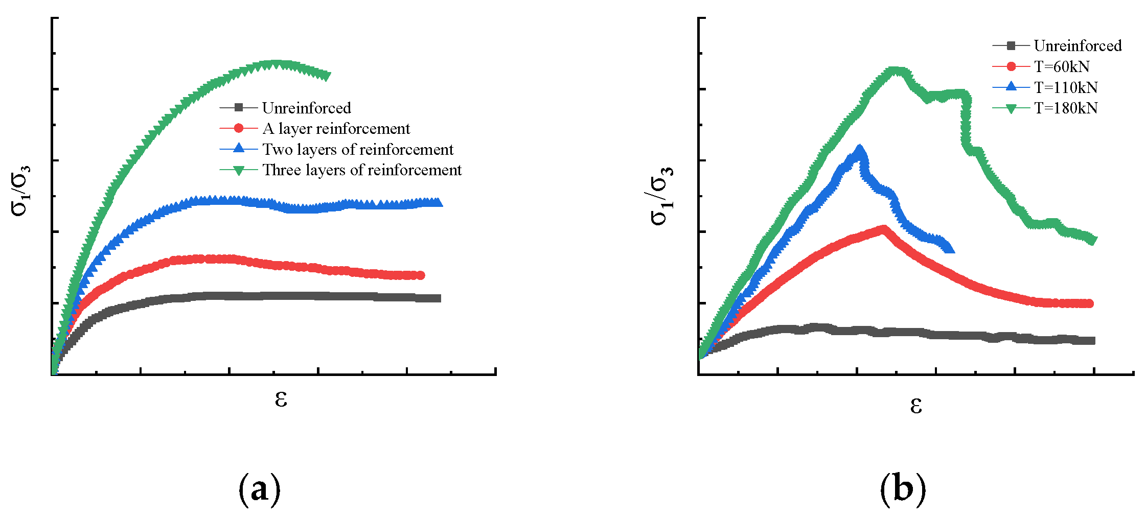
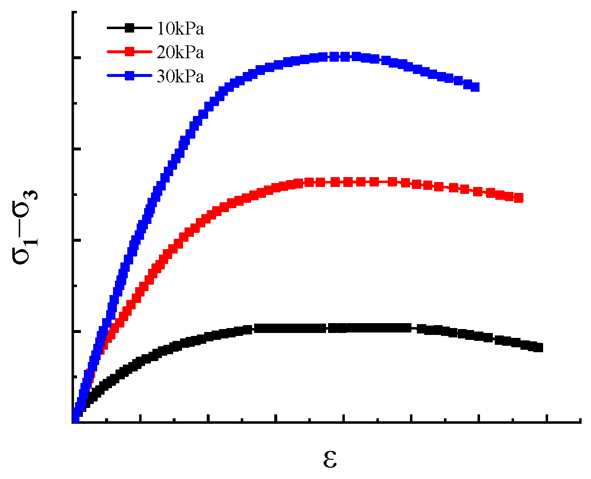
3. Reinforcement Mechanism of Soil Nail Support
4. Modeling Assumptions and Analysis of Soil Nail Support Reinforcement Theory
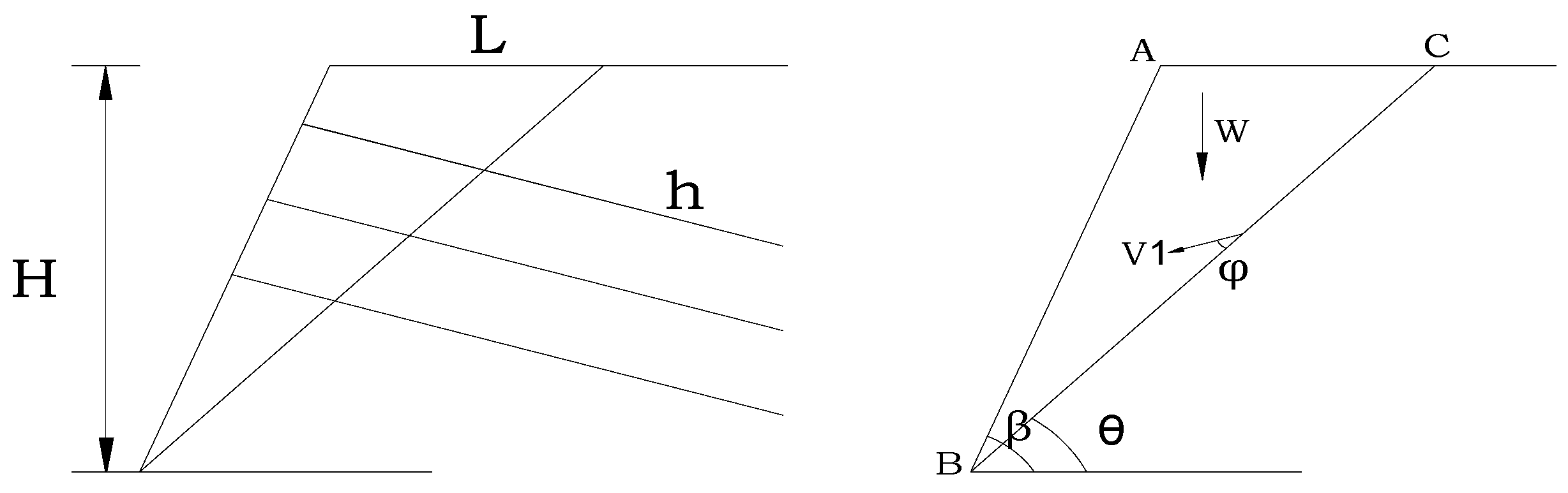
4.1. Establishment of Theoretical Model I and Method Verification
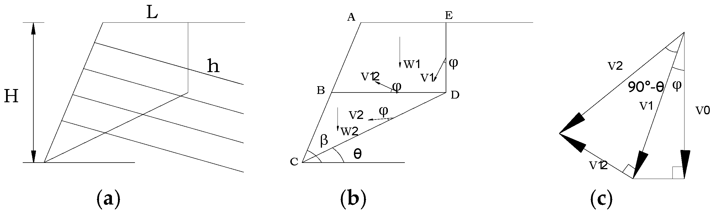
4.2. Establishment of Theoretical Model II and Deduction of Simplified Formula
- (1)
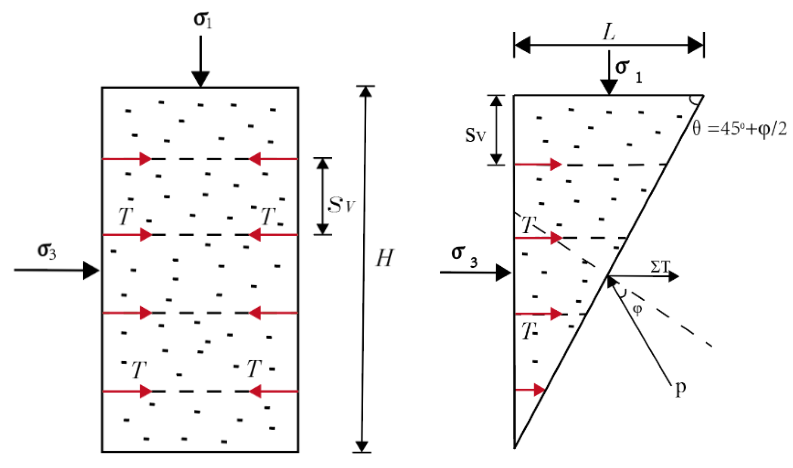
- Power Wi, consumed by the internal forces along the rupture surface in a soil nailing support structure, while taking into account the additional cohesive forces due to the action of soil nails, is given byAt this point,
- (2)
- When work is done by the soil under self-weight at an assumed velocity field rate, power We is given as
5. Exploring the Rupture Surface Forms of Soil Nail-Supported Structures
- (1)
- Through substituting into Equation (22), the critical height at which damage to the soil nailing support structure occurs can be obtained as
- (1)
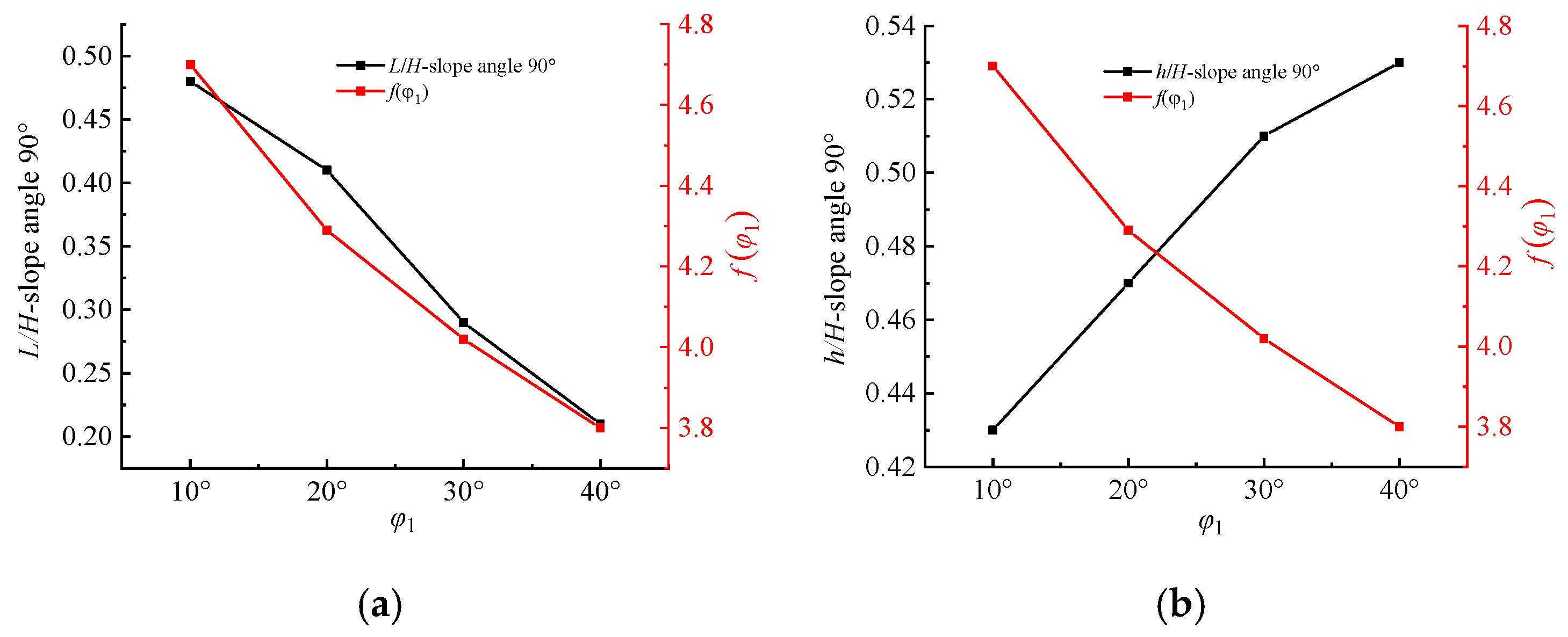
- As the angle of internal friction continues to increase, the rupture surface extends to the top of the pit or slope, thereby reducing the horizontal distance from the edge of the soil nailing support structure. Moreover, the tension cracks in the upper part of the soil nailing support structure gradually increase.
- (2)
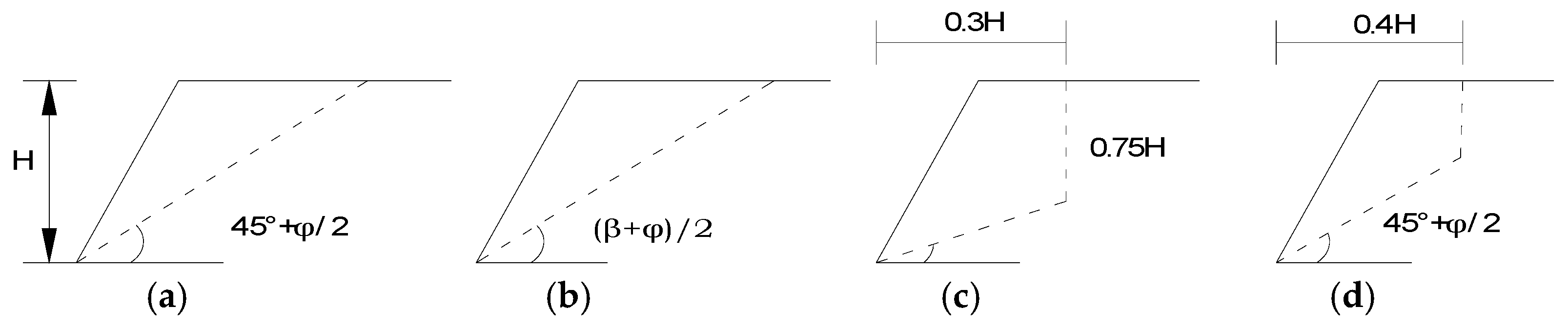
- When = 30°, L/H = 0.29 and h/H = 0.51. Under these conditions, the value of L is very close to that of L in the rupture surface form of the “Methodology of Cheng Liangkui” (mentioned in Figure 2c). However, h/H = 0.75 (given in Figure 2c), which is much different from that calculated using the method of the present work.
- (3)
- When = 20°, Table 1 shows that L/H = 0.41. Under these conditions, the value of L is very close to the value of L in the form of rupture surface of the “Methodology of Beijing University of Technology” (mentioned in Figure 2d). This indicates that with the present method, when , the distance from the top edge of the pit or slope to the rupture surface extending to the horizontal ground is close to 0.4H, and regardless of the internal friction angle, the value of L is 0.4H.
- (2)
- Through substituting into Equation (22), the critical height at which damage to the soil nailing support structure occurs can be obtained as
- (1)
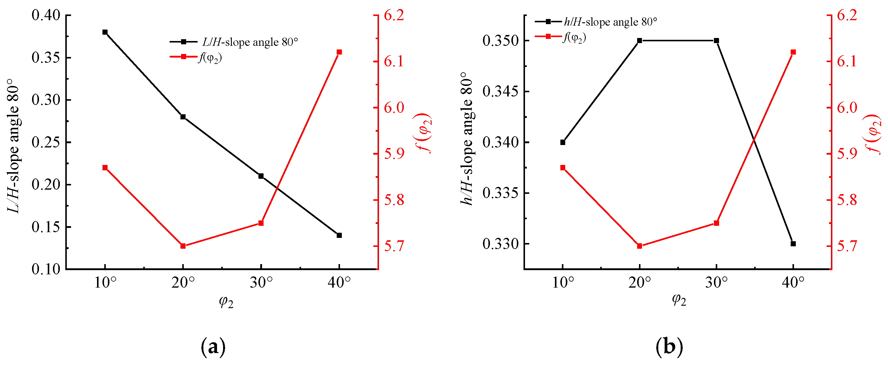
- When = 80°, as the angle of internal friction () continues to increase, the ratio of L/H gradually reduces, and the decrease is greater. The changes in the h/H ratio are reduced compared to in the previous case.
- (2)
- According to Table 2, under the premise of a certain slope angle of the pit or slope, different internal friction angles correspond to different rupture surface forms. In comparing Figure 2c,d, it can be seen that the form of slip fracture damage obtained through engineering experience is only the general shape of the rupture surface rather than all the forms of the slip fracture surface when L/H = 0.3 or 0.4.
- (3)
- Through substituting into Equation (22), the critical height at which damage to the soil nailing support structure occurs can be obtained as
- (1)
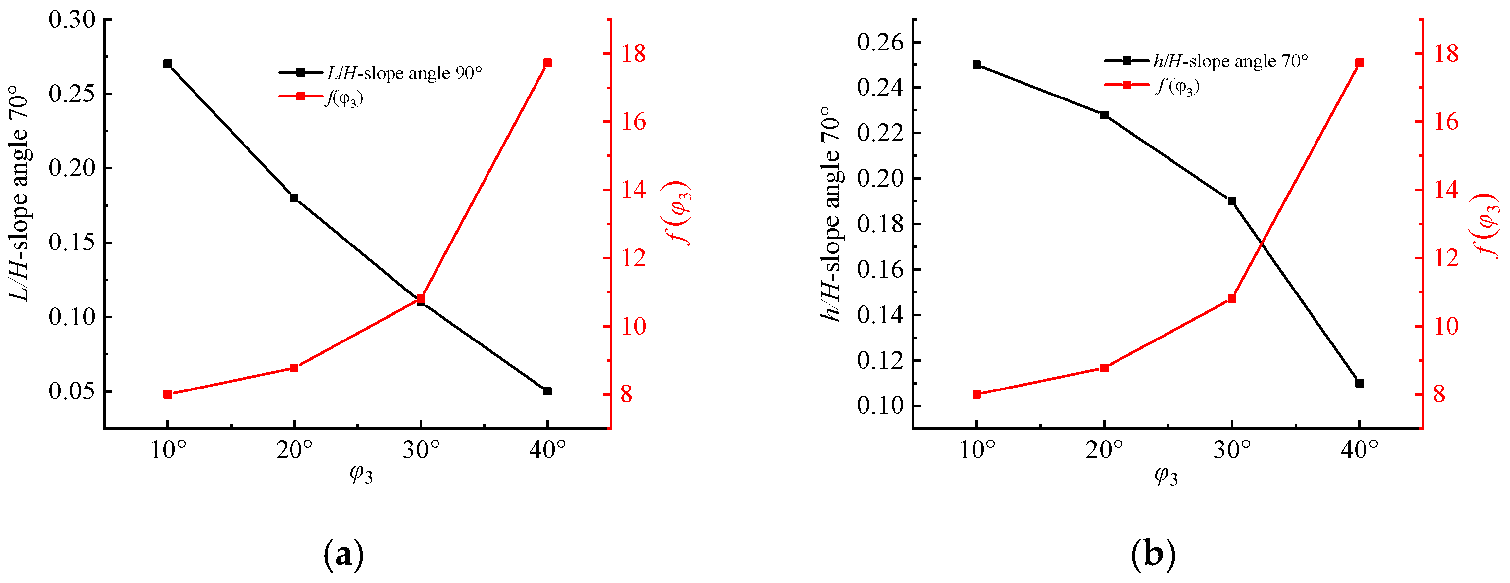
- When the slope angle = 70°, both L/H and h/H start to decrease, while the angle of internal friction continues to increase;
- (2)
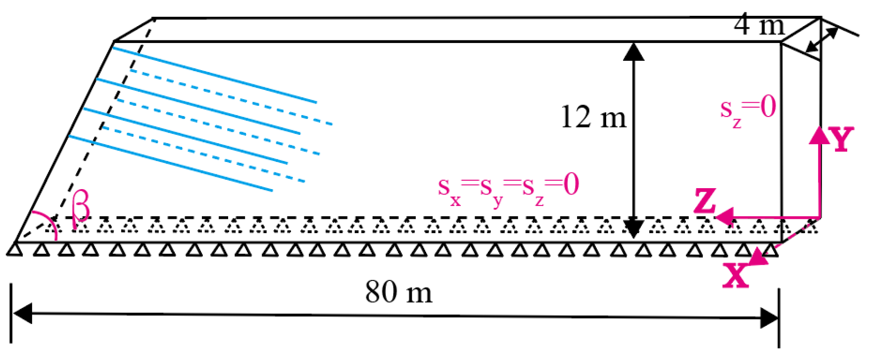
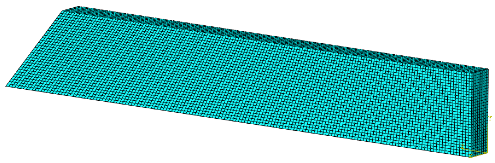
6. Example Verification
7. Conclusions
- (1)
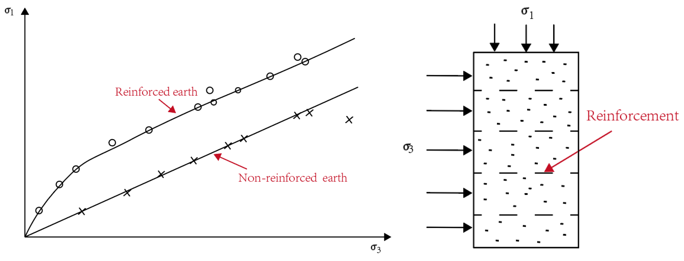
- Four common fracture surface forms in engineering are described, and the strengthening mechanism of internal friction angle and cohesion force after soil nail reinforcement is analyzed. Furthermore, the corresponding mathematical expressions are given.
- (2)
- Through the established theoretical model I and by combining the upper-limit theorem of plastic mechanics and the conservation of energy, the rationality of the assumed model and the used method is verified.
- (3)
- A theoretical analysis model is established considering the fracture surface form with deep drawing in a certain depth range at the top. The mathematical expressions of the fracture surface form in terms of h/H and L/H are derived based on plastic mechanics and energy conservation.
- (4)
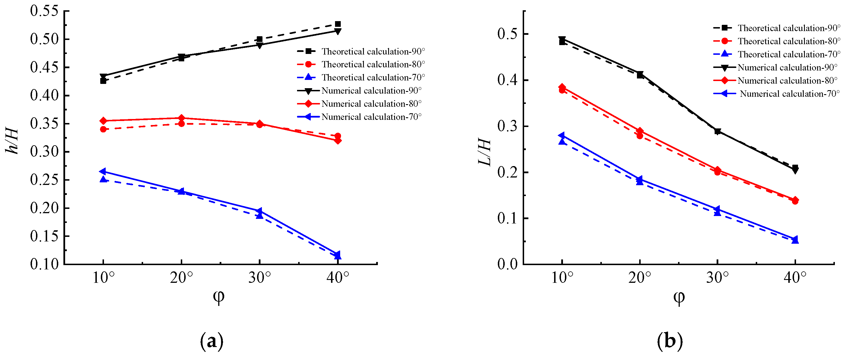
- Based on the reinforcement theory of soil nailing support structure, the fracture surface forms of the structure under different slope angles and different soil internal friction angles are analyzed. The fracture surface forms are compared with those in the literature. The results show the following:
- (a)
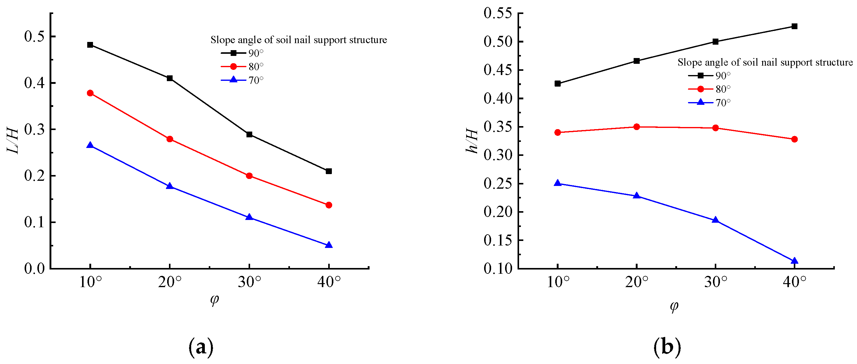
- L/H gradually decreases with the slope angle of the soil nailing support structure and with an increasing soil internal friction angle . This shows that the horizontal distance between the L value when the fracture surface extends to the top of the slope and the edge of the surface of the soil nailing structure is smaller under this condition.
- (b)
- h/H also decreases with the slope angle of soil nailing support structures, but h/H shows different patterns with an increasing soil internal friction angle. For = 90°, the greater the value, the greater the h/H value. When = 80°, h/H increases first and then decreases with increasing . When = 70°, the larger the value, the smaller the h/H value.
- (c)
- (d)
- When = 90° and = 20°, the value of L/H is close to the value of L/H in the form of the fracture plane in Figure 2d, indicating that when = 90° and , the horizontal distance of the fracture plane extending to the ground is close to 0.4H. Regardless of the angle of internal friction, L is always equal to 0.4H.
Author Contributions
Funding
Institutional Review Board Statement
Informed Consent Statement
Data Availability Statement
Acknowledgments
Conflicts of Interest
References
- Deng, E.; Xiang, Q.; Chan, J.C.L.; Dong, Y.; Tu, S.F.; Chan, P.W.; Ni, Y.Q. Increasing temporal stability of global tropical cyclone precipitation. npj Clim. Atmos. Sci. 2025, 8, 11. [Google Scholar] [CrossRef]
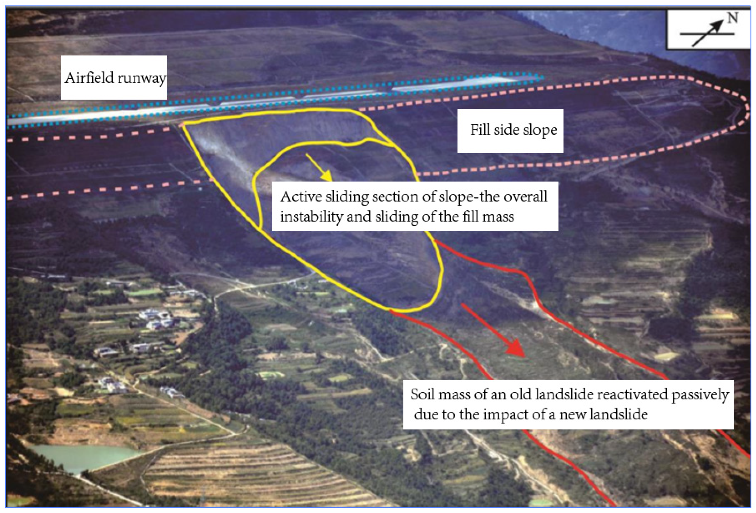
- Li, Y.R.; Wu, H.G.; Feng, J.; Lai, T.W. Numerical simulation analysis on the dynamic response of 12# landslide at the Panzhihua Airport of Sichuan Province. Chin. J. Geol. Hazard. Control 2018, 29, 26–31. [Google Scholar]
- Li, D.Y. Numerical Simulation Study on the Movement Process and Mechanism of Landslide No. 12 at Panzhihua Airport. Master’s Thesis, Chengdu University of Technology, Chengdu, China, 2017. [Google Scholar]
- Cheng, L.K.; Zhang, Z.M.; Yang, Z.Y. Practical Technology of Rock and Soil Reinforcement; Seismological Press: Beijing, China, 1994. [Google Scholar]
- JGJ 120-2012; China Academy of Building Research. Technical Specification for Retaining and Protection of Building Foundation Excavations. China Architecture & Building Press: Beijing, China, 2024.
- YB 9258-97; Central Research Institute of Building and Construction Co., Ltd.; MCC Group. Code for Technique of Building Foundation Pit Engineering. Metallurgical Industry Press: Beijing, China, 1997.
- Department of Civil Engineering, Tsinghua University. Specification for Soil Nailing in Foundation Excavations; Standards Press of China: Beijing, China, 1997. [Google Scholar]
- Yuan, H.S. Research on Rupture Angle of Soil-nailing Wall Structure. Constr. Technol. 2011, 40, 41–43. [Google Scholar]
- Hui, C.Y.; Zhu, Y.P.; Ye, S.H. Stability analysis of composite soil-nailing wall with prestressed anchors. Chin. J. Geotech. Eng. 2013, 35, 325–329. [Google Scholar]
- Li, J.J.; Feng, Z.Q.; Dong, J.; Guo, Y.T.; Li, X.B. Determination Method of Soil Nailing Wall’s Potential Slipping Surface. J. North Univ. China (Nat. Sci. Ed.) 2017, 38, 133–139. [Google Scholar]
- Zhao, W.; Wang, R.Q.; Nian, T.K. Analytical method for stability of anti dip rock slope based on flexural toppling failure mode. Chin. J. Rock. Mech. Eng. 2019, 38, 3287–3295. [Google Scholar]
- Li, Q.; Ling, T.Q.; Han, L.F.; Zhang, R.G. Random Search Method of Fracture Surface for Seismic Stability of Reinforced Retaining Wall. J. Southwest Jiaotong Univ. 2021, 56, 801–808. [Google Scholar]
- Zhou, F.X.; Zhu, S.W.; Liang, Y.W.; Zhao, W.C. Exact analysis of soil slope stability by using variational limit equilibrium method. Chin. J. Geotech. Eng. 2023, 45, 1341–1346. [Google Scholar]
- Wang, S.G.; Teng, Y.J.; Duan, Q.W.; Li, Q.R.; Zhang, X.C. Deformation of soil nailing wall and inner forces of soil nails. China Civ. Eng. J. 2015, 50, 97–109. [Google Scholar]
- Shan, R.L.; Zheng, Y.; Wei, L.F. Model tests on supporting mechanism of soil nailing wall in silty clay deep foundation. Chin. J. Geotech. Eng. 2016, 38, 1175–1180. [Google Scholar]
- Zhang, F.L. Model Test Study on Soil Nailing Wall Retaining Structure in Loess Foundation Pit. Master’s Thesis, Lanzhou Jiao tong University, Lanzhou, China, 2013. [Google Scholar]
- Luo, Q.; Xiong, S.J.; Wang, T.F.; Huang, Y.; Zhang, L. Analysis on slip surface characteristics of backfill and earth pressure of balance weight retaining wall under translation movement. J. Southeast Univ. (Nat. Sci. Ed.) 2022, 52, 547–556. [Google Scholar]
- Zhao, L.C.; Liu, Y.J.; Zong, H.; Xu, Y.C.; Wang, B.; Qi, L.M. Study on different slope shapes and stability under same slope angle. China Saf. Sci. J. 2022, 32, 140–144. [Google Scholar]
- Wang, H.H.; Guo, M.Z. Analysis of Toppling Failure of Anti Toppling Rock Slope Based on Numerical Manifold Method. Technol. Earthq. Disaster Prev. 2021, 16, 346–351. [Google Scholar]
- Bian, K.; Liu, J.; Hu, X.J.; Li, P.C.; Chen, L.Z.; Liu, Z.P. Study on failure mode and dynamic response of rock slope with non-persistent joint under earthquake. Rock. Soil. Mech. 2018, 39, 3029–3037. [Google Scholar]
- Guo, S.F.; Fu, J.Y.; Zhang, P.; Li, N. Deformation-damage mechanism and failure mode of creeping bedding rock landslides controlled by faults. China Earthq. Eng. J. 2025, 3, 1–12. [Google Scholar]
- Zhou, Y.; Wang, Z.Z. Improvement of internal stability analysis method of soil nailing wall. Rock. Soil. Mech. 2016, 7, 356–362. [Google Scholar]
- Liao, Y.; Sun, L.J.; Liu, X. Analysis on the Random Variables’ Influence on Outside Stability of Soil Nailed Wall. Sci. Technol. Eng. 2013, 13, 6934–6938. [Google Scholar]
- Lou, G.C.; Bu, J.Q. Field Monitoring of a High Slope of Weak Rocks with Soil-nailing Support and Determination of the Slip Surface. China Civ. Eng. J. 2005, 38, 106–109+114. [Google Scholar]
- Ahmed, A.; Ugai, K.; Yang, Q.Q. Assessment of 3D Slope Stability Analysis Methods Based on 3D Simplified Janbu and Hovland Methods. Int. J. Geomech. 2012, 12, 81–89. [Google Scholar] [CrossRef]
- Park, D.; Michalowski, R.L. Three-dimensional stability assessment of slopes in intact rock governed by the Hoek-Brown failure criterion. Int. J. Rock. Mech. Min. 2020, 137, 104522. [Google Scholar] [CrossRef]
- Brideau, M.A.; Pedrazzini, A.; Stead, D.; Froese, C.; Jaboyedoff, M.; Zeyl, D.V. Three-dimensional slope stability analysis of South Peak, Crowsnest Pass, Alberta, Canada. Landslides 2011, 8, 139–158. [Google Scholar] [CrossRef]
- Giger, M.W.; Krizek, R.J. Stability analysis of vertical cut with variable corner angle. Soils Found. 1975, 15, 63–71. [Google Scholar] [CrossRef] [PubMed]
- Giger, M.W.; Krizek, R.J. Stability of vertical corner cut with concentrated surcharge load. J. Geotech. Eng. Div. 1976, 102, 31–40. [Google Scholar] [CrossRef]
- Tan, D.; Sarma, S.K. Finite element verification of an enhanced limit equilibrium method for slope analysis. Géotechnique 2008, 58, 481–487. [Google Scholar] [CrossRef]
- Noroozi, M.; Jalali, S.E.; Yarahmadi-Bafghi, A.R. 3D key-group method for slope stability analysis. Int. J. Numer. Anal. Met. 2012, 36, 1780–1792. [Google Scholar] [CrossRef]
- Cui, J.Y. Mode Analysis of Sliding Plane for Foundation Pit Anchor. Chin. J. Rock. Mech. Eng. 2003, 22, 337–340. [Google Scholar]
- Zhang, Q.X.; Huo, D.; Wang, B.H. A Method of Designing Soil-nailing Wall Based on Sliding Sphenoid-mass Limit Analysis. Ind. Constr. 2002, 32, 337–340. [Google Scholar]
- Zhang, W.M.; Cai, Z.Y.; Lai, Z.Z. Limit analysis and centrifuge model tests of reinforced retaining wall. Res. Waterborne Transp. 1995, 1, 55–63. [Google Scholar]
- Broms, B.B. Fabric reinforced retaining walls. In Proceedings of the International Geotechnical Symposium on Theory and Practice of Earth Reinforcement, Fukuoka, Japan, 5–7 October 1988; pp. 3–31. [Google Scholar]
- Futaki, M.; Suzuki, H.; Yamato, S. Super large triaxial compression tests on reinforced sand with high strength geogrid. In Proceedings of the 4th International Conference on Geotextiles, Geomembranes and Related Products, The Hague, The Netherlands, 28 May–1 June 1990; Volume 2, pp. 759–764. [Google Scholar]
- Jiang, Z.X. Engineering Application of Culmann’s Formula on Critical Height of Slope. Geotech. Eng. Technol. 2007, 21, 217–220. [Google Scholar]
- Casin, M.A.; Kirkby, M.J. Slope Morphology and Formation Process; Science Press: Beijing, China, 1984. [Google Scholar]
- Ma, P.; Qin, S.Q.; Sun, Q. Computation of lateral soil pressure on soil nailing wall considering cohesion force and cut slope angle. Chin. J. Geotech. Eng. 2007, 29, 1888–1891. [Google Scholar]
- Jiang, Z.X. Discussion on sliding angle formula in “Computation of lateral soil pressure on soil nailing wall considering cohesion force and cut slope angle”. Chin. J. Geotech. Eng. 2008, 06, 952. [Google Scholar]
- Li, G.X. Experimental research and analysis on breaking surface of reinforced earth retaining wall. J. Railway Eng. Soc. 2001, 03, 125–128. [Google Scholar]
- Liang, B.; Sun, Y.Q. A study on the tensile failure of reinforced earth retaining wall with model test. Chin. J. Geotech. Eng. 1995, 17, 83–87. [Google Scholar]
- Gong, X.N. Soil Plastic Mechanics; Zhejiang University Press: Hangzhou, China, 1999. [Google Scholar]
- Chen, H.F.; Sapri, A.F. Elastic and Plastic Mechanics; China Architecture & Building Press: Beijing, China, 2004. [Google Scholar]
- Zhu, Y.P.; Ye, S.H.; Mo, Y. Analysis and treatment of a deep foundation pit accident in Xining, Qinghai Province. Chin. J. Geotech. Eng. 2010, 32, 404–409. [Google Scholar]

| 10° | 20° | 30° | 40° | |
|---|---|---|---|---|
| 4.70 | 4.29 | 4.02 | 3.80 | |
| 0.48 | 0.41 | 0.29 | 0.21 | |
| 0.43 | 0.47 | 0.51 | 0.53 |
| 10° | 20° | 30° | 40° | |
|---|---|---|---|---|
| 5.87 | 5.7 | 5.75 | 6.12 | |
| 0.38 | 0.28 | 0.21 | 0.14 | |
| 0.34 | 0.35 | 0.35 | 0.33 |
| 10° | 20° | 30° | 40° | |
|---|---|---|---|---|
| 8 | 8.78 | 10.81 | 17.72 | |
| 0.27 | 0.18 | 0.11 | 0.05 | |
| 0.25 | 0.228 | 0.19 | 0.11 |
| Weight/kN/m3 | Friction Angle /° | Cohesion/kPa | Poisson’s Ratio | Elastic Modulus /MPa | Slope Angle /° | Soil Nail Inclination /° | Soil Nail Length /m |
|---|---|---|---|---|---|---|---|
| 18 | 10/20/30/40 | 13 | 0.38 | 40 | 70/80/90 | 15 | 8 |
Disclaimer/Publisher’s Note: The statements, opinions and data contained in all publications are solely those of the individual author(s) and contributor(s) and not of MDPI and/or the editor(s). MDPI and/or the editor(s) disclaim responsibility for any injury to people or property resulting from any ideas, methods, instructions or products referred to in the content. |
© 2025 by the authors. Licensee MDPI, Basel, Switzerland. This article is an open access article distributed under the terms and conditions of the Creative Commons Attribution (CC BY) license (https://creativecommons.org/licenses/by/4.0/).
Share and Cite
Li, F.; Jiang, C.; Hao, Z.; Han, J.; Meng, X.; Yao, M. Study on Failure Surface Morphology of Supporting Structures Under Extreme Climate–Mechanical Coupling Effects Based on Reinforcement Theory. Appl. Sci. 2025, 15, 4874. https://doi.org/10.3390/app15094874
Li F, Jiang C, Hao Z, Han J, Meng X, Yao M. Study on Failure Surface Morphology of Supporting Structures Under Extreme Climate–Mechanical Coupling Effects Based on Reinforcement Theory. Applied Sciences. 2025; 15(9):4874. https://doi.org/10.3390/app15094874
Chicago/Turabian StyleLi, Feilong, Changshan Jiang, Zhenli Hao, Jinbao Han, Xianfeng Meng, and Miaoxian Yao. 2025. "Study on Failure Surface Morphology of Supporting Structures Under Extreme Climate–Mechanical Coupling Effects Based on Reinforcement Theory" Applied Sciences 15, no. 9: 4874. https://doi.org/10.3390/app15094874
APA StyleLi, F., Jiang, C., Hao, Z., Han, J., Meng, X., & Yao, M. (2025). Study on Failure Surface Morphology of Supporting Structures Under Extreme Climate–Mechanical Coupling Effects Based on Reinforcement Theory. Applied Sciences, 15(9), 4874. https://doi.org/10.3390/app15094874