Abstract
Passive, compound, and active augmented heat transfer (AHT) methods in a countercurrent flow concentric tube heat exchanger (CCTHE) were explored and examined in this work. The finite volume method using ANSYS Fluent 2021 R2 was applied to evaluate the fluid flow and heat transfer characteristics of a CCTHE in each AHT study. The influence of the circular perforated insert at varied quantities (N) was analyzed in a passive AHT study. A comparable heat transfer improvement of 41.8% was recorded at an insert quantity of N = 7; however, a notable decreasing trend in the thermal performance factor (α) indicated that pressure drop increases as the number of inserts increases. In the active AHT study, the inner pipe rotation at 300 rad/s resulted in a heat transfer rate enhancement of 428%. The compound AHT method employed rotating perforated inserts at various rotational speeds, which resulted in a heat transfer rate increase of 47.5% at 300 rad/s and N = 7. This work demonstrated how each type of flow disturbance affected the heat transfer rate inside a CCTHE and investigated the effectiveness of each method through the evaluation of α.
1. Introduction
The industrial demand for concentric tube heat exchangers (CTHE) has increased in recent years due to their design simplicity, space consideration, lower cost, and efficiency [1]. However, the heat transfer area limitation of a CTHE can result in poor heat transfer in most applications. To improve the performance of CTHEs while maintaining their compact design, augmented heat transfer (AHT) methods were introduced and are continuously being developed. AHT demonstrates a modification of flow to achieve better temperature distribution inside the CTHE and, in doing so, promotes better heat transfer. AHT methods are classified as passive, active, and compound, and these methods were studied and used in different heat transfer applications in the industry [2], namely steaming and condensation [3,4,5], boiling and evaporation systems [6,7], refrigeration and air-conditioning, and pharmaceutical and medical applications.
Various research studies focus on different passive AHT since it is relatively easier to install. Table 1 summarizes various types of inserts used and their impact on heat transfer rate.
Table 1.
Type of inserts used and the effect on heat transfer rate.
Despite significant improvements in heat transfer rates, the shape complexity of developed inserts often leads to high manufacturing costs and fabrication constraints. On the other hand, active and compound AHT methods are less explored compared to passive AHT [14,15]. Table 2 shows some of the active and compound AHT types used in the past and their corresponding effect on heat transfer rate.
Table 2.
Types of active AHT used and the effect on heat transfer rate.
Previous studies indicate that each AHT method contributes to the improvement of heat transfer rate. It is therefore important to study the effect of combining different methods: passive, active, and compound AHT methods. As previous literature focused on isolated passive enhancement techniques, the understanding of the application of active and compound AHT methods in heat transfer applications, particularly rotating circular perforated inserts and rotating inner pipes, respectively, remains limited and insufficiently explored.
The novelty of this research lies in the integrated approach to enhancing heat exchanger performance by assessing all heat transfer methods—passive, compound, and active AHT—through the strategic incorporation of uncomplicated inserts that are not difficult to fabricate. Specifically, this study initiated the integration of a rotating circular perforated insert with an actively rotating inner pipe, which has not been systematically examined previously. This study also simulated the effect of using passive, active, and compound AHT methods in one CTHE system, which has not been performed in the past.
The present study (1) investigated the heat transfer effects of varying the quantity (N) of perforated inserts along the inner tube length of the countercurrent flow concentric tube heat exchanger (CCTHE), (2) examined the impact of rotating the perforated insert at various rotational speeds on the CCTHE performance, and (3) demonstrated the effectiveness of incorporated passive, active, and compound AHT methods in terms of thermal performance factor (α). Hence, this research will greatly support and benefit the establishment of a comprehensive framework for designing next-generation heat exchangers with higher efficiency across industrial applications.
2. Methods
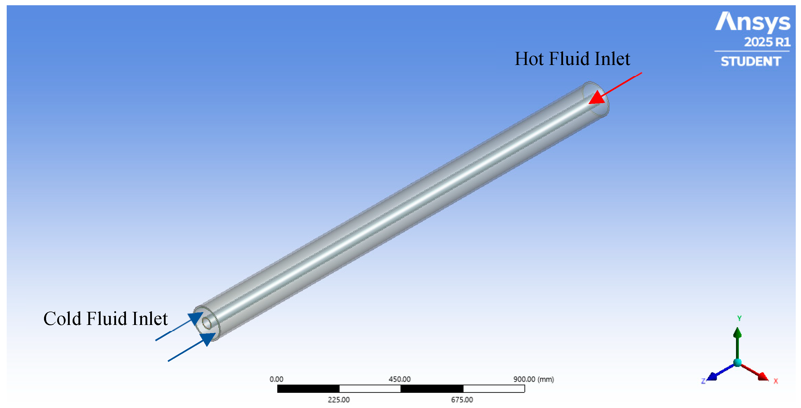
2.1. Description of the Problem
This study focused on a CCTHE configuration wherein the hot liquid toluene was passed through the inner pipe, and cold water flowed through the annular outer pipe side. The fluids assigned were assumed to have constant viscosities and densities throughout the heat transfer process. The inner and outer pipe materials were specified as copper and steel, respectively, and the fluid and material properties were defined by the ANSYS Fluent 2021 R2 material database, as shown in Table 3.
Table 3.
Fluid and solid properties derived from ANSYS Fluent 2021 R2 database.
This study comprised the following parts: (i) a study on grid dependence and parameter sensitivity analysis, (ii) validation of the numerical method, (iii) simulation and determination of the impacts of passive, (iv) active, and (v) compound AHT methods on the CCTHE heat transfer characteristics.
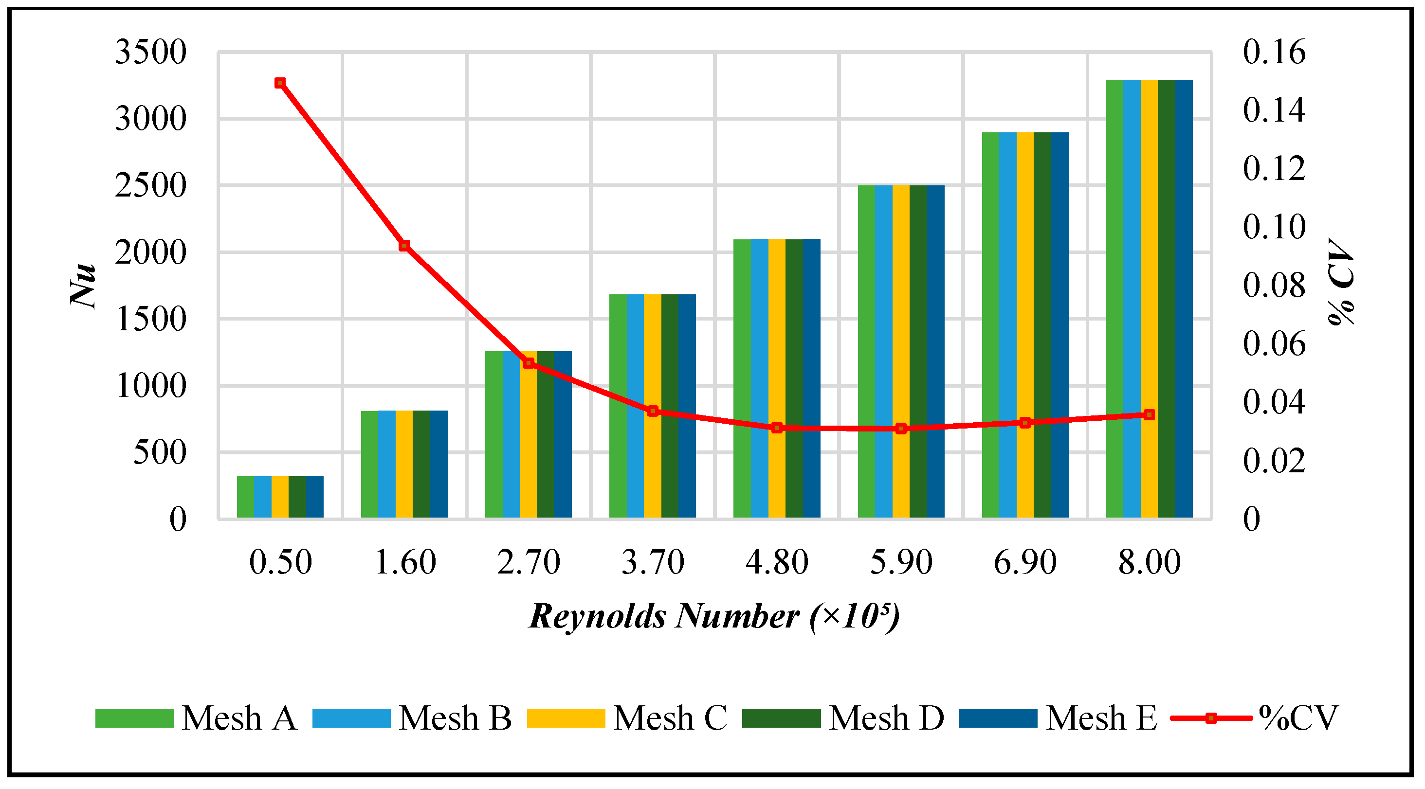
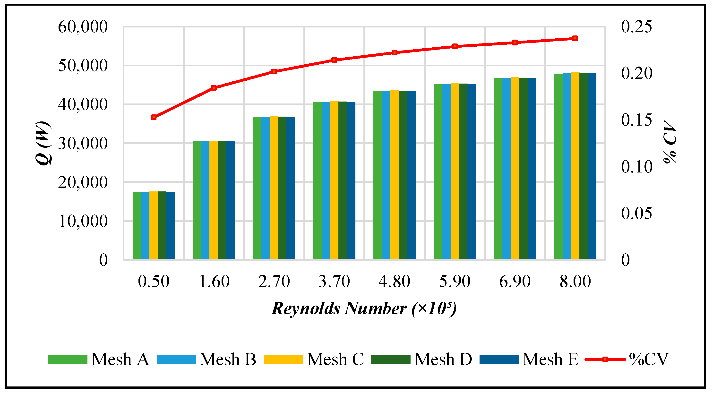
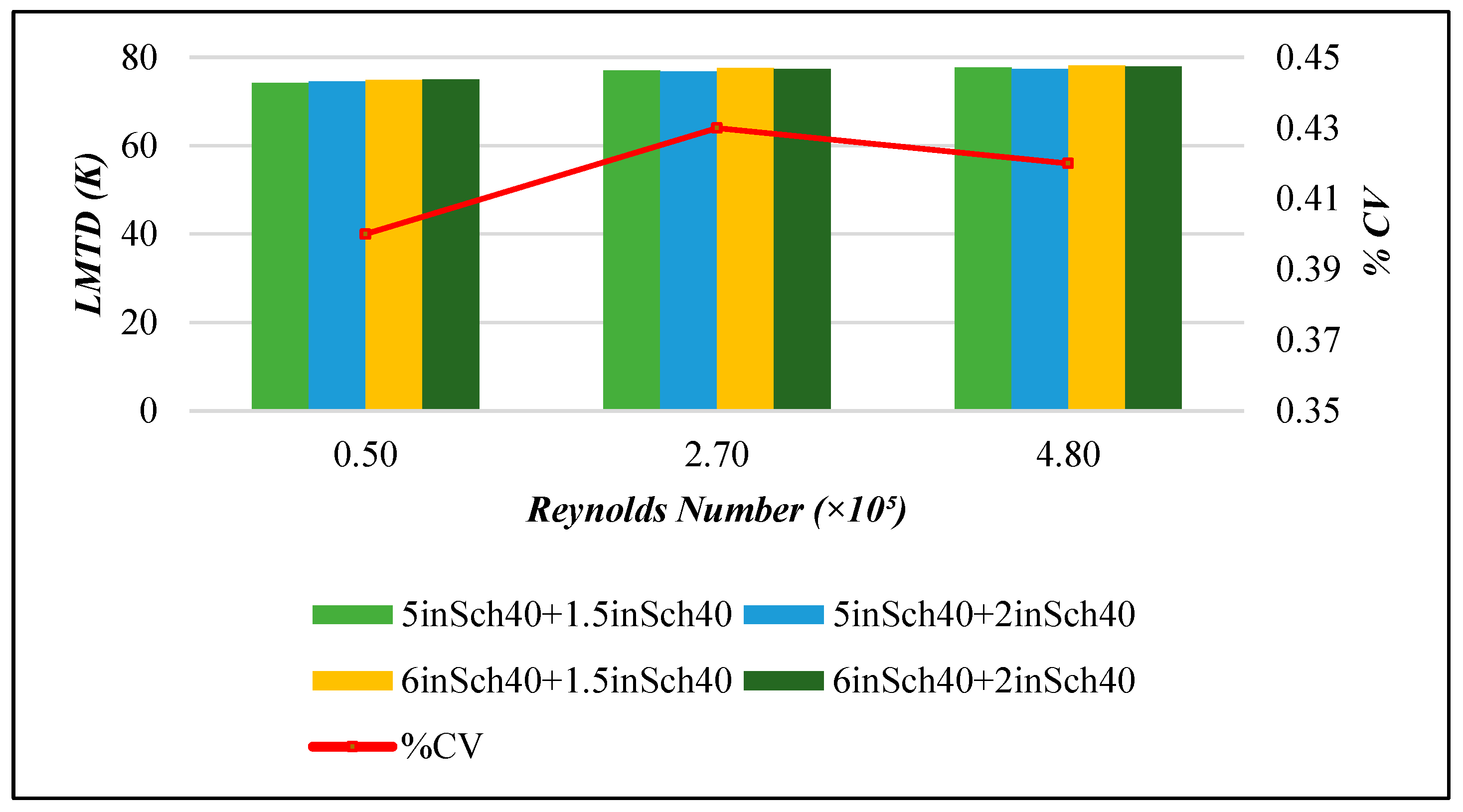
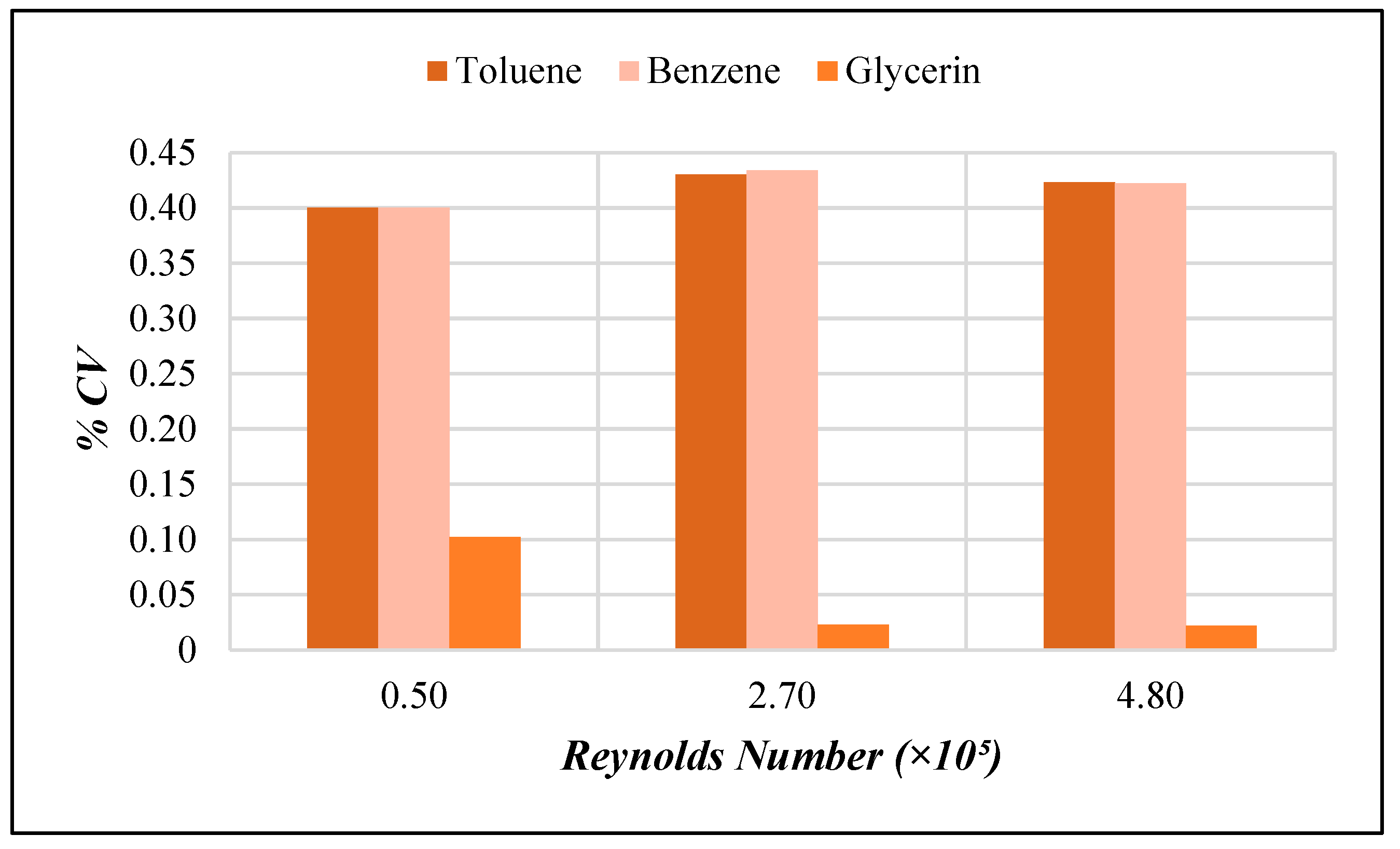
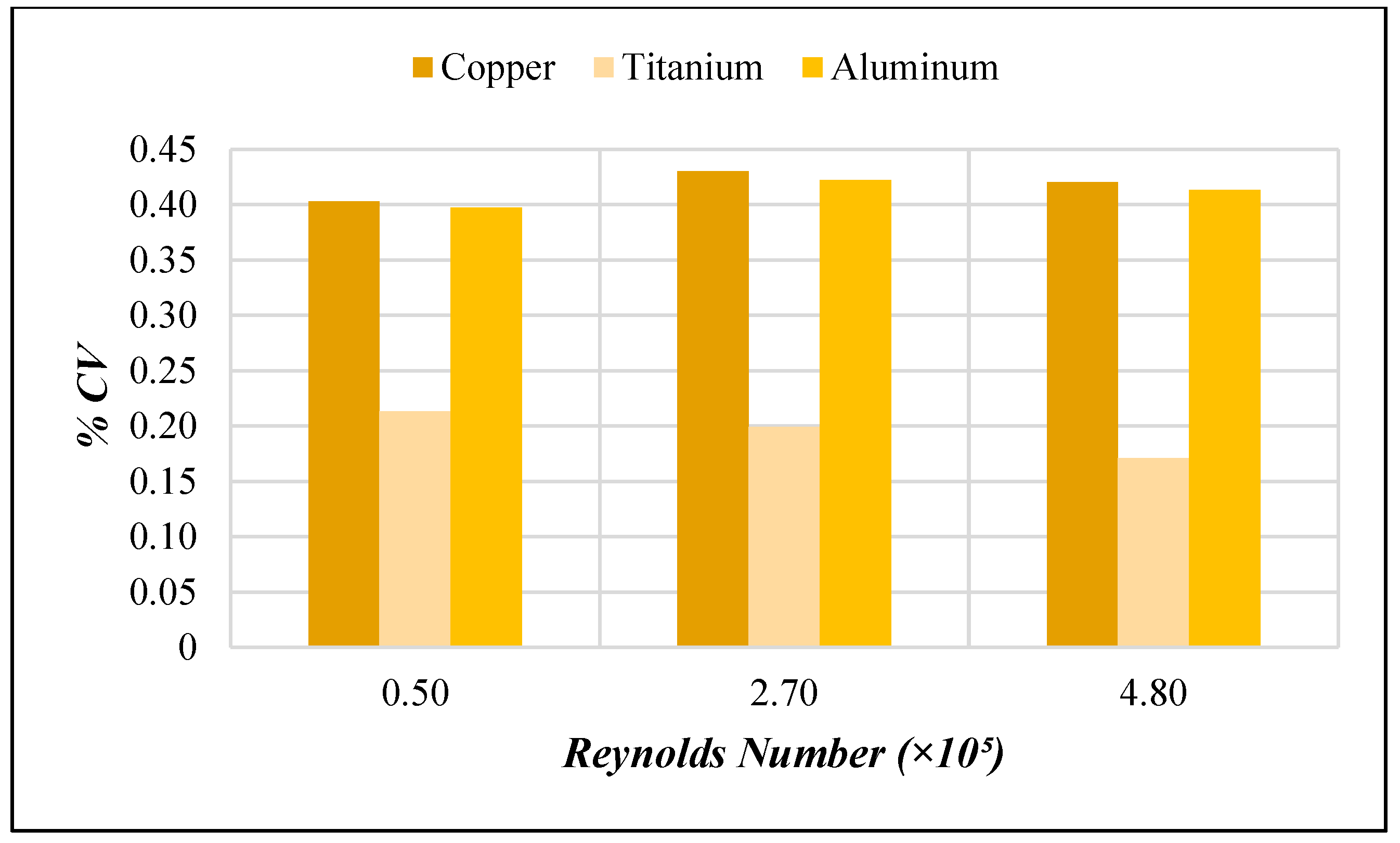
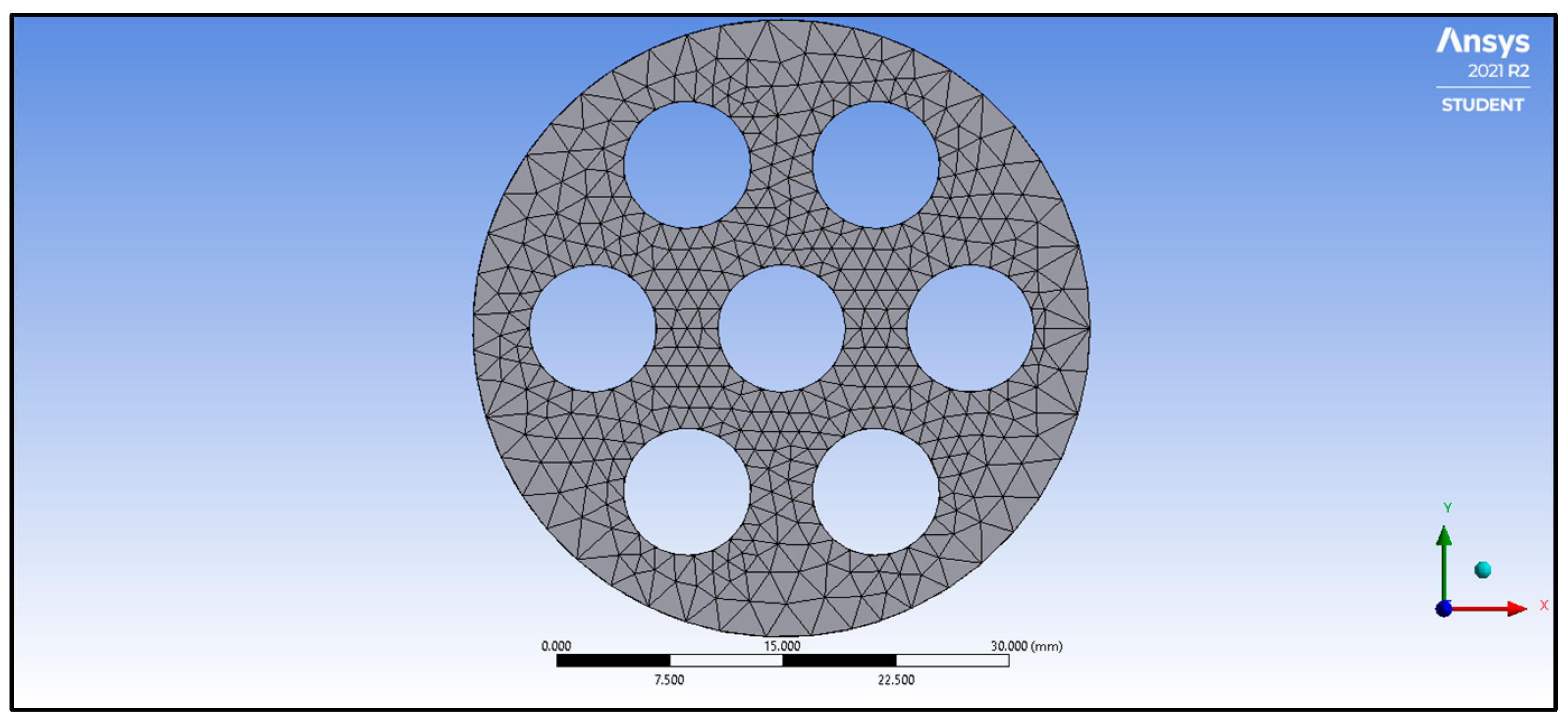
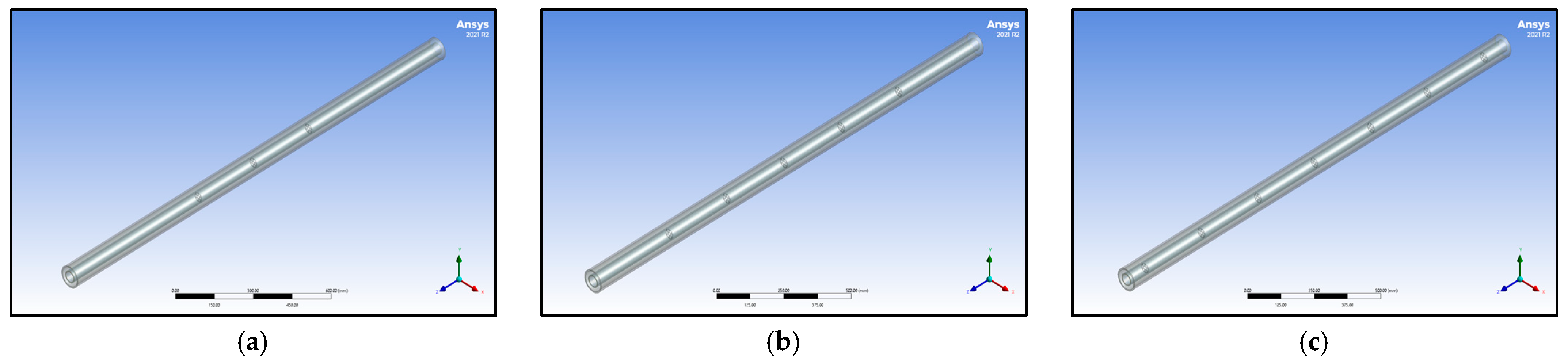
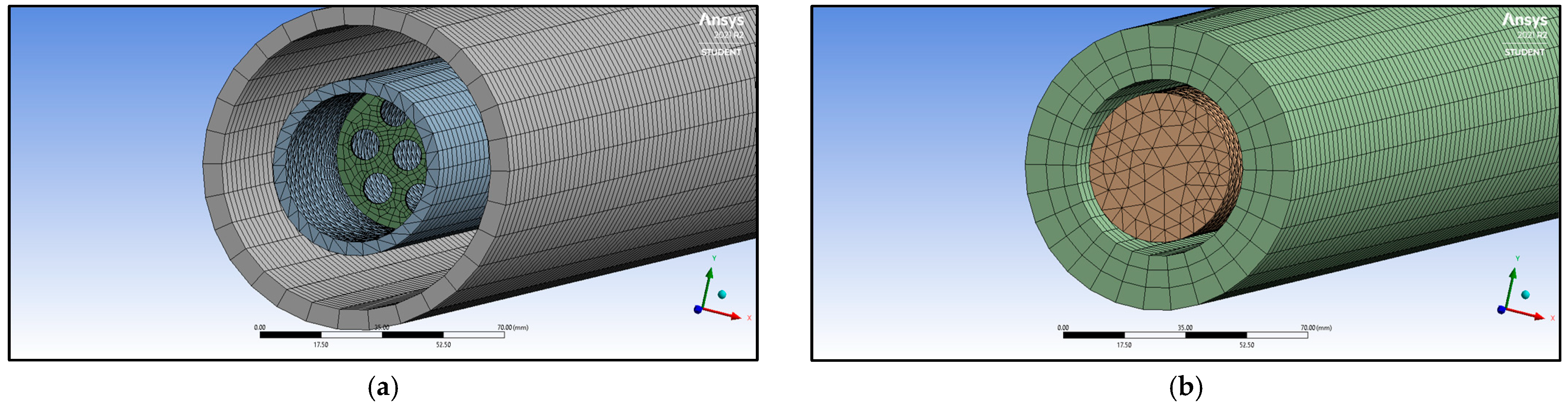
2.1.1. Study on Grid Dependence and Parameter Sensitivity Analysis
Given the complexity of the model and to ensure the correctness of solutions, a mesh sensitivity test at various Reynold numbers was conducted at various mass design points. The test evaluated the impact of the number of mesh elements in a test grid on the Nu and Q, as can be seen in Figure 1 and Figure 2. It was found that the average percent coefficient of variation between the values of Nu and Q are 0.058% and 0.209%, respectively, indicating that the model has reached mesh independence. Accordingly, Mesh A was employed in this study for simple and optimized calculation [21].
Figure 1.
Impact of mesh variations on Nu output.
Figure 2.
Impact of mesh variations on Q output.
A sensitivity test on model dimensions was also done for different inner and outer diameters, as seen in Figure 3. As can be seen, the %CV for LMTD at three different Reynolds numbers is less than 5%, still indicative that the model can be utilized at different tube dimensions.
Figure 3.
Impact of pipe diameter variations on LMTD output.
The fluid type and solid material were also varied to test the sensitivity of the baseline model to changing fluid and solid conditions. Here, the impact was tested at various Reynolds numbers and model dimensions. As can be seen in Figure 4 and Figure 5, the %CV for LMTD is less than 5%, indicating that the model used is independent of fluids and solids employed.
Figure 4.
Impact of fluid variations on LMTD output.
Figure 5.
Impact of solid variations on LMTD output.
2.1.2. Numerical Model Validation Approach
The numerical model is validated through theoretical calculations made at varying hot toluene inlet mass flow rates (1, 3, 5, 7, 9, 11, 13, and 15 kg/s) and at a constant cold water inlet mass flow rate of 6 kg/s. To maximize the number of elements in ANSYS Fluent 2021 R2 for the validation, the nominal size considered for the inner and outer pipe is 1½ in Sch.40 and 5 in Sch.40, respectively. The initial conditions for model validation are summarized in Table 4.
Table 4.
Initial conditions for numerical model validation.
In the theoretical calculation, Nu was evaluated using the Dittus–Boelter correlation given by Equation (1).
where Re is the Reynolds number and Pr is the Prandtl number. Toluene outlet temperature (Th,o), water outlet temperature (Tc,o), and total heat transfer rate () were evaluated and compared with the values generated from ANSYS Fluent 2021 R2.
Relative root mean square error (RRMSE), expressed as Equation (2), was used as an indicator in model validation, whereas model agreement was considered excellent when RRMSE < 10%, good when 10% < RRMSE < 20%, fair if 20% < RRMSE < 30%, and poor if RRMSE > 30% [22].
where x is the number of data sets, Dm and Dc refer to the model data and calculated data, respectively, and is the mean model data.
2.1.3. Passive AHT Study
A base case solution was made for comparison of results. Table 5 provides a summary of flow specifications applicable for both the base case and AHT methods while Figure 6 shows the orientation of hot and fluid flow.
Table 5.
CCTHE Flow Specification for the base case and AHT studies.
Figure 6.
Flow configuration of CCTHE.
The passive AHT study focused on a circular insert at varied quantities (N) across the length of the CCTHE inner pipe. Figure 7 shows the circular insert at a fixed hole diameter of 8.5 mm. The quantity of insert across the inner pipe was varied at N = 3, 5, and 7, represented by Figure 8. Additionally, each insert had an offset distance of 300 mm from each other.
Figure 7.
Circular perforated insert with hole diameter, = 8.5 mm.
Figure 8.
Isometric view of the arrangement of circular perforated inserts along the inner pipe length: (a) N = 3, (b) N = 5, and (c) N = 7.
After performing the simulation, , , f, and Nu were generated. The thermal performance factor, , expressed as Equation (3), was also evaluated. This parameter represented the ratio of the relative effect of change in heat transfer rate to change in friction factor and is used to measure the effectiveness of the passive AHT technique applied.
where Nu and f refer to the Nusselt number and friction factor for CCTHE with inserts, respectively, while Nu0 and f0 refer to the Nusselt number and friction factor for CCTHE without heat transfer enhancement, respectively.
2.1.4. Active AHT Study
The active AHT study was performed by incorporating a rotating inner pipe in the system. The rotational speed () was set as the main parameter in ANSYS Fluent 2021 R2 and is varied at = 20, 50, 100, 150, 200, 250, and 300 rad/s. , , f, and Nu were obtained from the simulation and was evaluated.
2.1.5. Compound AHT Study
A combined passive and active method was considered in the compound AHT study, whereas the CCTHE was comprised of rotating circular perforated inserts (N = 7) inside a rotating inner pipe. The rotational speed () was varied at = 100, 200, and 300 rad/s.
2.2. Governing Equations
Model assumptions include the following: (i) three-dimensional steady-state flow, (ii) incompressible Newtonian fluids, (iii) neglected viscous dissipation, (iv) disregarded volume dilation, (v) neglected external and gravitational bodies, (vi) no internal heat generation, and (vii) zero heat leakage due to radiation. The simplified basic governing equations in vector notations are expressed as Equations (4)–(6).
where (m/s), (kg/m3), p (Pa), (kg/m-s), I, E (J/kg), k (W/m-K), and T (K) refer to the velocity, density, pressure, viscosity, unit tensor, energy density, thermal conductivity, and temperature of the fluid, respectively. Based on the given assumptions, the partial differential equations involved in the solution are given in Equation (7) for the continuity Equations (8)–(10) for the momentum equations, and (11) for the equation of energy. Detailed boundary conditions used in the simulation of each CCTHE case are discussed in the succeeding section, Section 2.3.
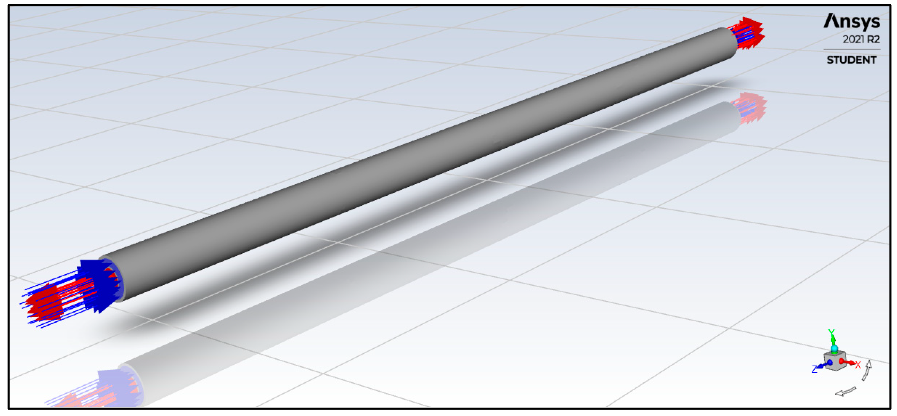
2.3. Numerical Model and Boundary Conditions
Computational fluid dynamics (CFD) software ANSYS Fluent 2021 R2 incorporating a pressure-based solver was utilized in this study. The countercurrent flow CTHE was discretized into fluid and solid domains, whereas the angle of curvature was fixed at 18°. The generated mesh grid for solid and fluid domains is depicted in Figure 9, respectively.
Figure 9.
Generated CCTHE with inserts mesh grid: (a) solid domain and (b) fluid domain.
The resulting computational domain for the system is presented in Figure 10. A realizable turbulence model with enhanced wall treatment was employed for the numerical calculation using the finite volume method [13]. The SIMPLE algorithm was utilized to solve the velocity–pressure coupling, and the second-order upwind scheme was selected to discretize the continuity, momentum, energy, turbulence kinetic energy, and dissipation rate equations [23]. Moreover, the least square cell-based method was used for gradient calculation.
Figure 10.
Computational Domain of the countercurrent flow CTHE.
Cell zone conditions follow the specifications made in Table 4 while the initial and boundary conditions are indicated in Table 6.
Table 6.
CCTHE boundary conditions.
3. Results
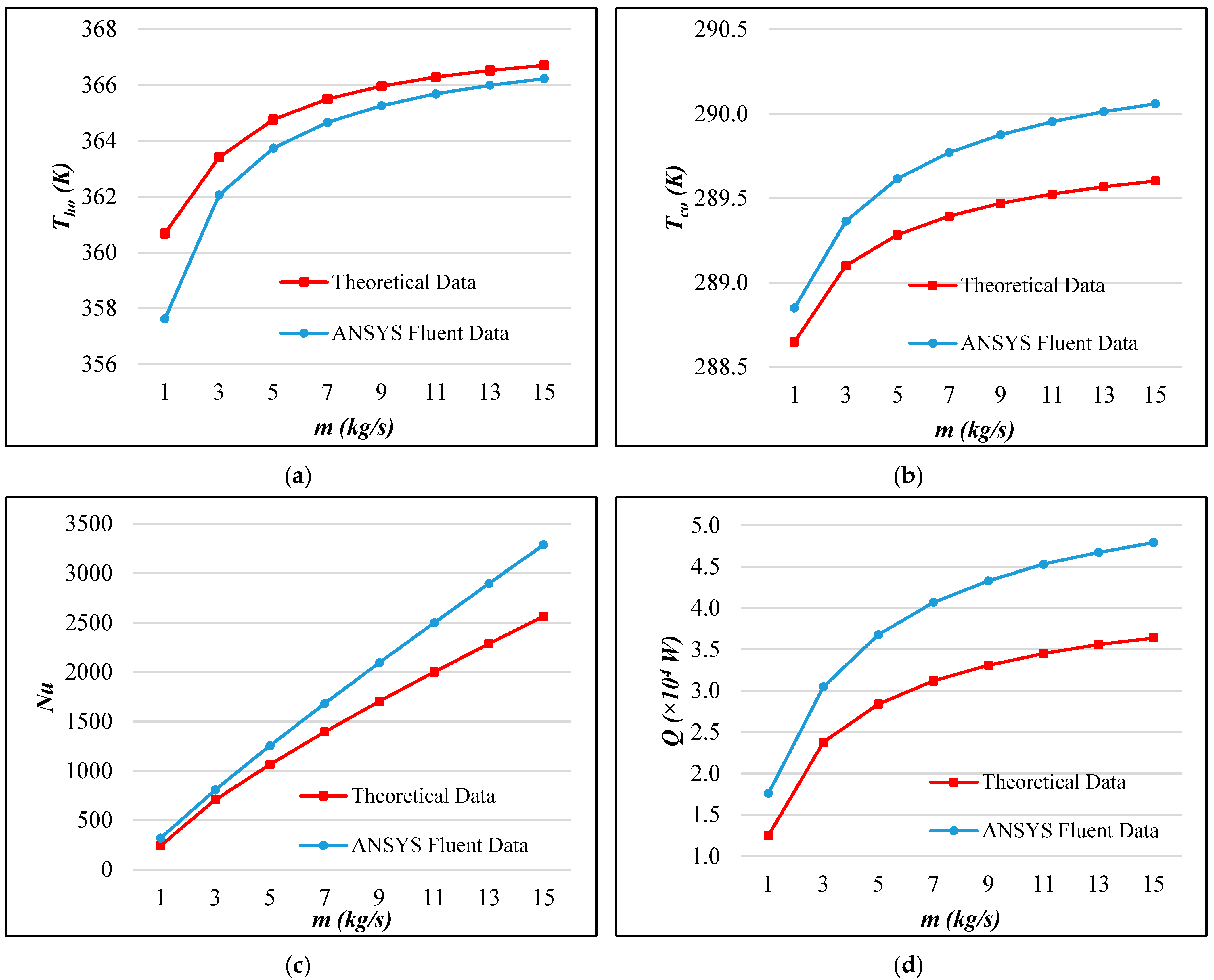
3.1. Validation of Numerical Model
The flow regime at varied inlet flow rates satisfies all the conditions of the Dittus–Boelter correlation. The theoretical data calculated and the ANSYS Fluent 2021 R2 data for Th,o, Tc,o, Nu, and are illustrated in Figure 11.
Figure 11.
Comparison of theoretical and simulated values: for (a) Th,o, (b) Tc,o, (c) Nu, and (d) .
Calculated RRMSE for each parameter, summarized in Table 7, ranged from excellent to fair. This level of agreement between the theoretical and simulated data was acceptable and indicated that the numerical model is valid and can be utilized for further calculation [22].
Table 7.
Evaluated RRMSE for each parameter.
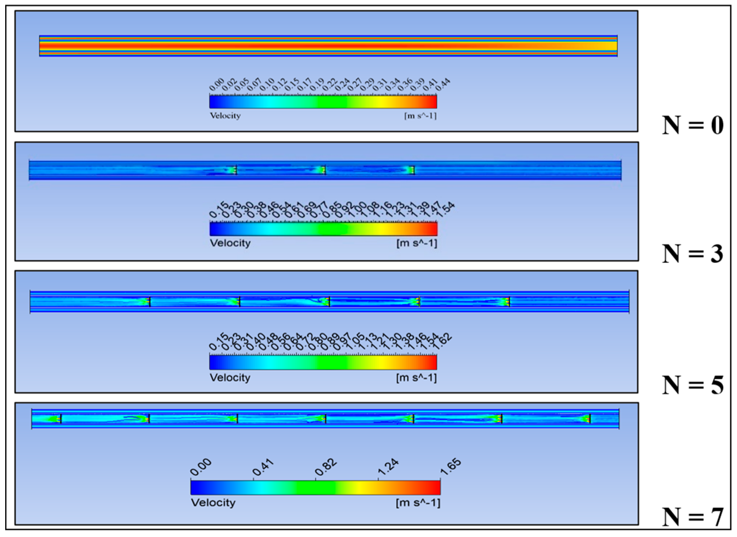
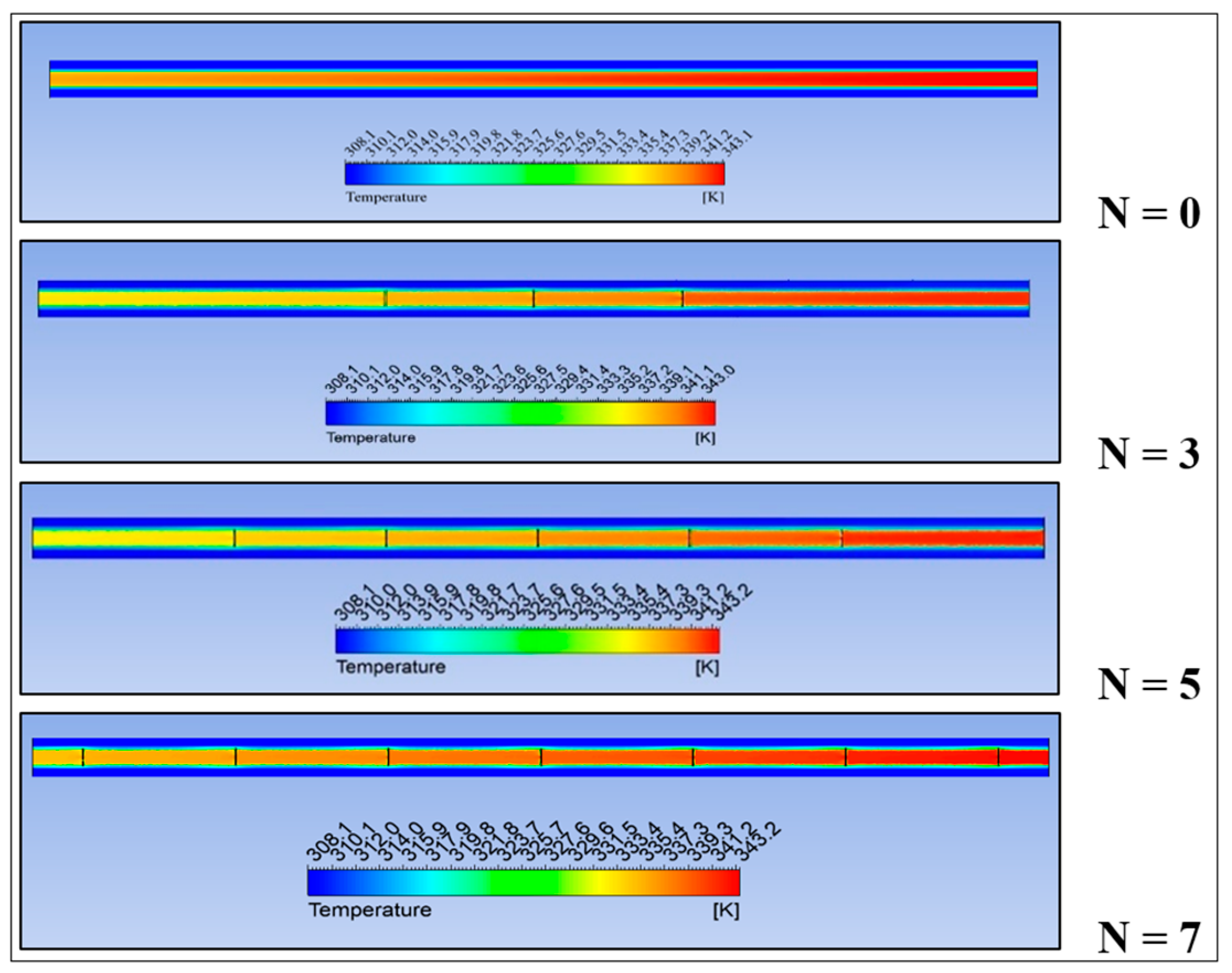
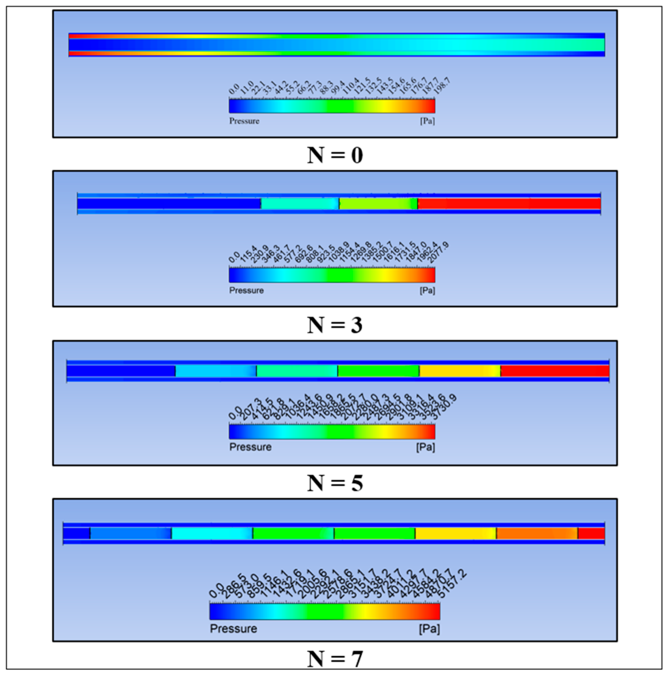
3.2. Passive AHT Study
The velocity, temperature, and pressure profiles at various perforated insert quantities (N) are presented in Figure 12, Figure 13, and Figure 14 respectively. It can be observed that as N is increased along the inner tube length, the flow disruption becomes remarkable in the hot fluid region.
Figure 12.
Velocity profile of CCTHE at varied insert quantity (N).
Figure 13.
Temperature Profile of CCTHE at varied insert quantity (N).
Figure 14.
Pressure profile of CCTHE at varied insert quantity (N).
Figure 15 shows that a smooth flow without any disruption forms an inactive thermal layer at the boundary of the inner pipe and hot fluid domain, while Figure 16 shows the formation of swirls when inserts are positioned along the inner pipe. This flow disturbance stipulated better mixing of the inefficient boundary layer and the core fluid, providing a better temperature distribution as depicted in Figure 13.
Figure 15.
Inactive thermal layer at N = 0.
Figure 16.
Formation of swirls and vortices in the presence of inserts.
As seen in Figure 17, the increase in the quantity of inserts amplified along the tube length. This can be interpreted as a major drawback since a large increment might incur additional pumping costs [24].
Figure 17.
Pressure drop () and friction factor (f) at varied insert quantity (N).
Nu rapidly increased with the increase in pipe inserts, as can be observed in Figure 18, indicating the dominance of active convection during the heat exchange. However, the decreasing trend of α was notable. This implied that the pressure drop was high compared to the heat transfer rate enhancement [25]. On the other hand, Figure 19 shows that the heat transfer rate () is enhanced with the increasing value of N. The maximum result is comparable with the heat transfer enhancement obtained by previous studies, as presented in Table 8.
Figure 18.
and Nu at varied insert quantity (N).
Figure 19.
%Q Enhancement at varied insert quantity (N).
Table 8.
Heat transfer enhancement comparison.
3.3. Active AHT Study
The rotational speed of the inner pipe (rad/s), , was varied and set as an input parameter in ANSYS Fluent 2021 R2. Figure 20 illustrates the impact of on and f. It can be observed that the maximum pressure increment of 578 Pa is relatively lower compared to an increment of 5202 Pa evaluated in the passive AHT study. It is also remarkable that f did not rise rapidly as was increased.
Figure 20.
Pressure drop () and friction factor (f) at varied rotational speed (ω).
A maximum α of 2.02, as can be seen in Figure 21, indicated that the AHT method was effective considering both the convective heat transfer and the friction loss. Moreover, a remarkable increase in heat transfer rate by up to 4.28 times can be depicted in Figure 22. This enhancement is attributed to the formation of turbulence and recirculation as the pipe rotates [26]. Figure 23 presents the build-up of swirls and vortices across the pipe length that induces rapid thermal mixing. On the other hand, Figure 24 shows the temperature profile of the hot fluid domain at the inner pipe inlet and inner pipe outlet. Consequently, heat transfer enhancement occurred more efficiently. These comparable results denote that the active AHT method applied is promising in terms of parameters such as low friction loss and high convective heat transfer and heat transfer rate.
Figure 21.
and Nu at varied rotational speeds (ω) during Active AHT.
Figure 22.
% Enhancement at varied rotational speed (ω).
Figure 23.
Rapid thermal mixing and formation of swirls and vortices across the inner tube length (ω = 20 rad/s).
Figure 24.
Hot fluid domain temperature profile (ω = 20 rad/s): (a) inner pipe inlet and (b) inner pipe outlet.
3.4. Compound AHT Study
In the compound AHT study, a CCTHE with N = 7 perforated inserts rotated at ω = 100, 200, and 300 rad/s were examined. It can be observed in Figure 25 that aside from swirls, magnified vortices are being formed as the inserts rotate. This leads to better thermal mixing, thereby increasing the heat transfer rate by up to 47.5% at 300 rad/s. The temperature profile in Figure 26 shows a better temperature distribution than the passive AHT alone.
Figure 25.
Formation of swirls and vortices as the insert is rotated (N = 7, ω = 300 rad/s).
Figure 26.
Temperature profile in CCTHE with rotating inserts (N = 7; ω = 300 rad/s).
Although the compound AHT gave a better improvement in heat transfer rate than the passive method, the α remains less than 1, as referred to in Figure 27. This reinforces that the pressure increment incurred by the presence of rotating inserts was significant relative to the convective heat transfer. Nevertheless, the trend of α is increasing as opposed to the observation made in a static perforated insert; hence, the introduction of movement to the inserts can lead to a higher heat transfer efficiency.
Figure 27.
and Nu at varied rotational speeds (ω) during Compound AHT.
4. Conclusions
In the present study, numerical analysis was performed for different AHT methods, namely passive, compound, and active. Circular perforated inserts were used in passive AHT, a rotating inner pipe was used in active AHT, and rotating circular perforated inserts were utilized in compound AHT. The proposed applications in each method provided a significant heat transfer rate improvement. Consequently, the main findings were as follows:
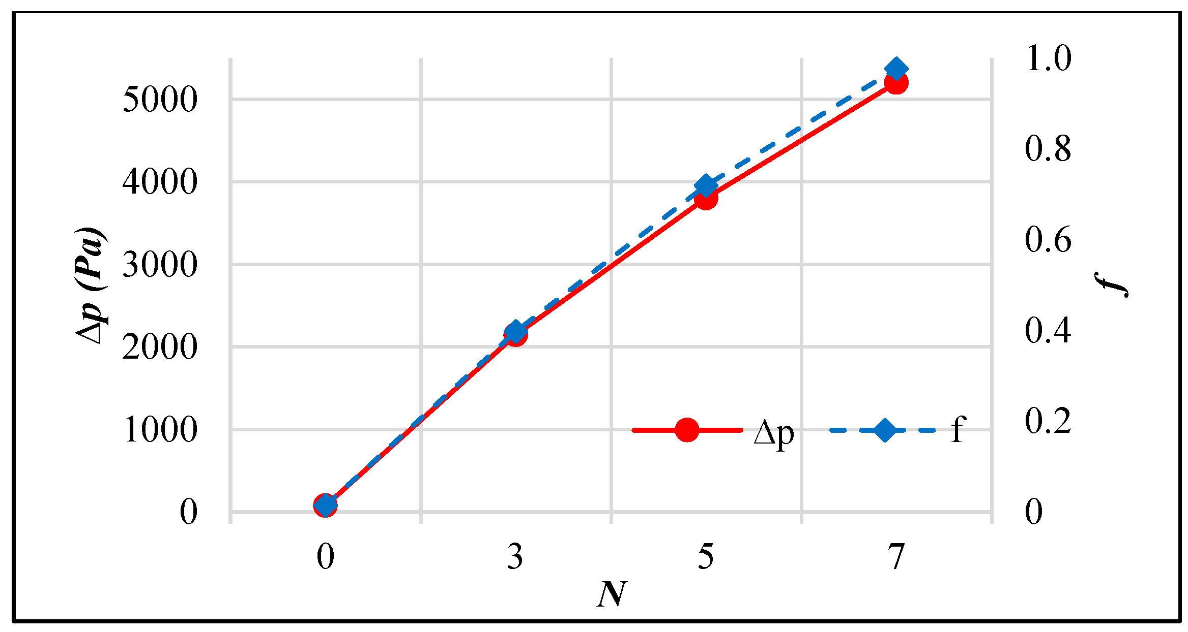
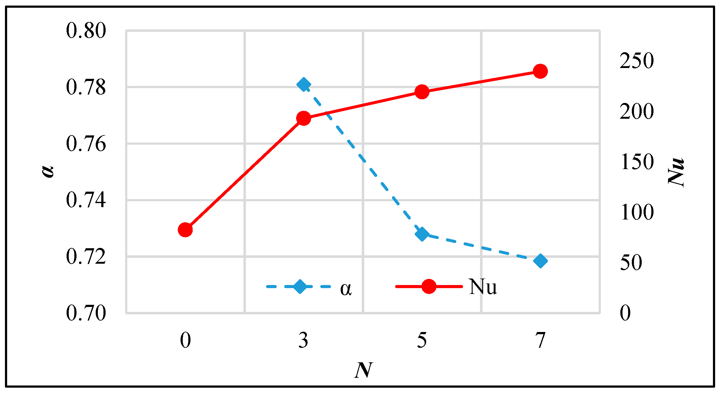
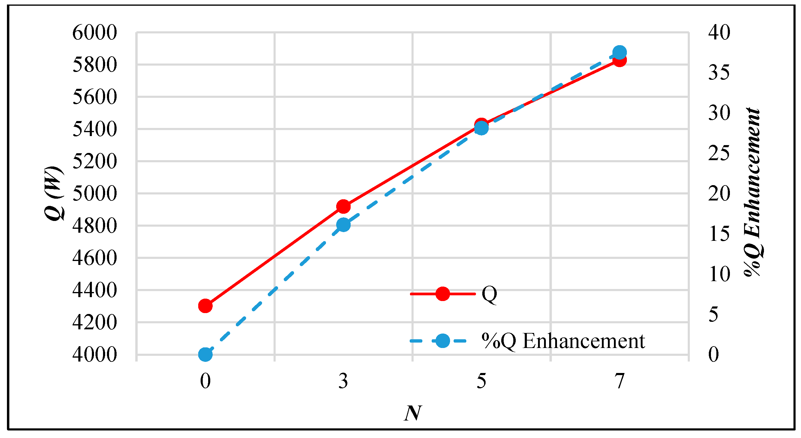
- Passive AHT: At N = 7, the heat transfer rate of the static circular perforated pipe increased by 41.8%. However, the thermal performance factor of 0.72 was relatively low due to the abrupt increase in pressure drop, which is not well-balanced with the convective heat transfer improvement.
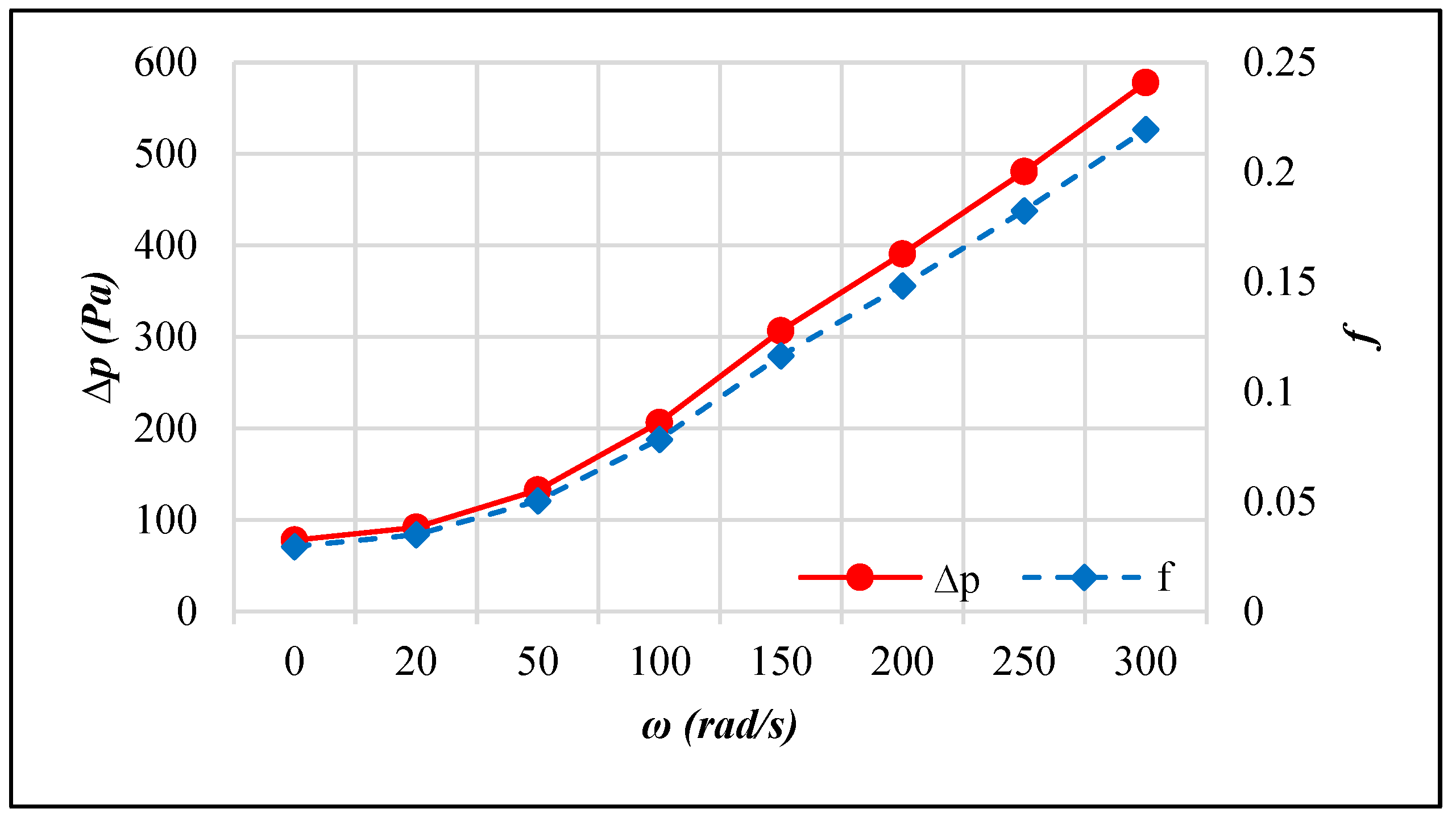
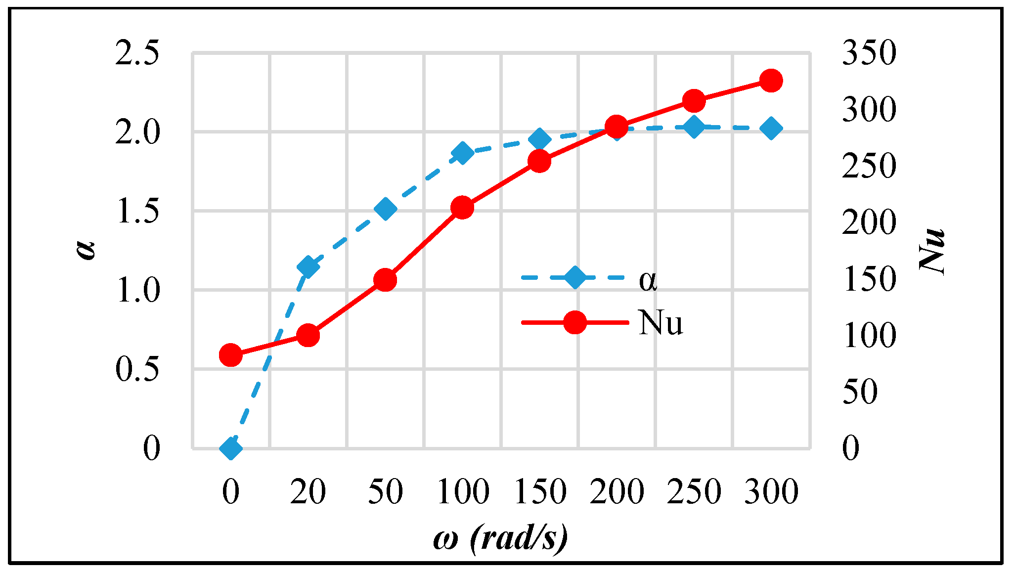
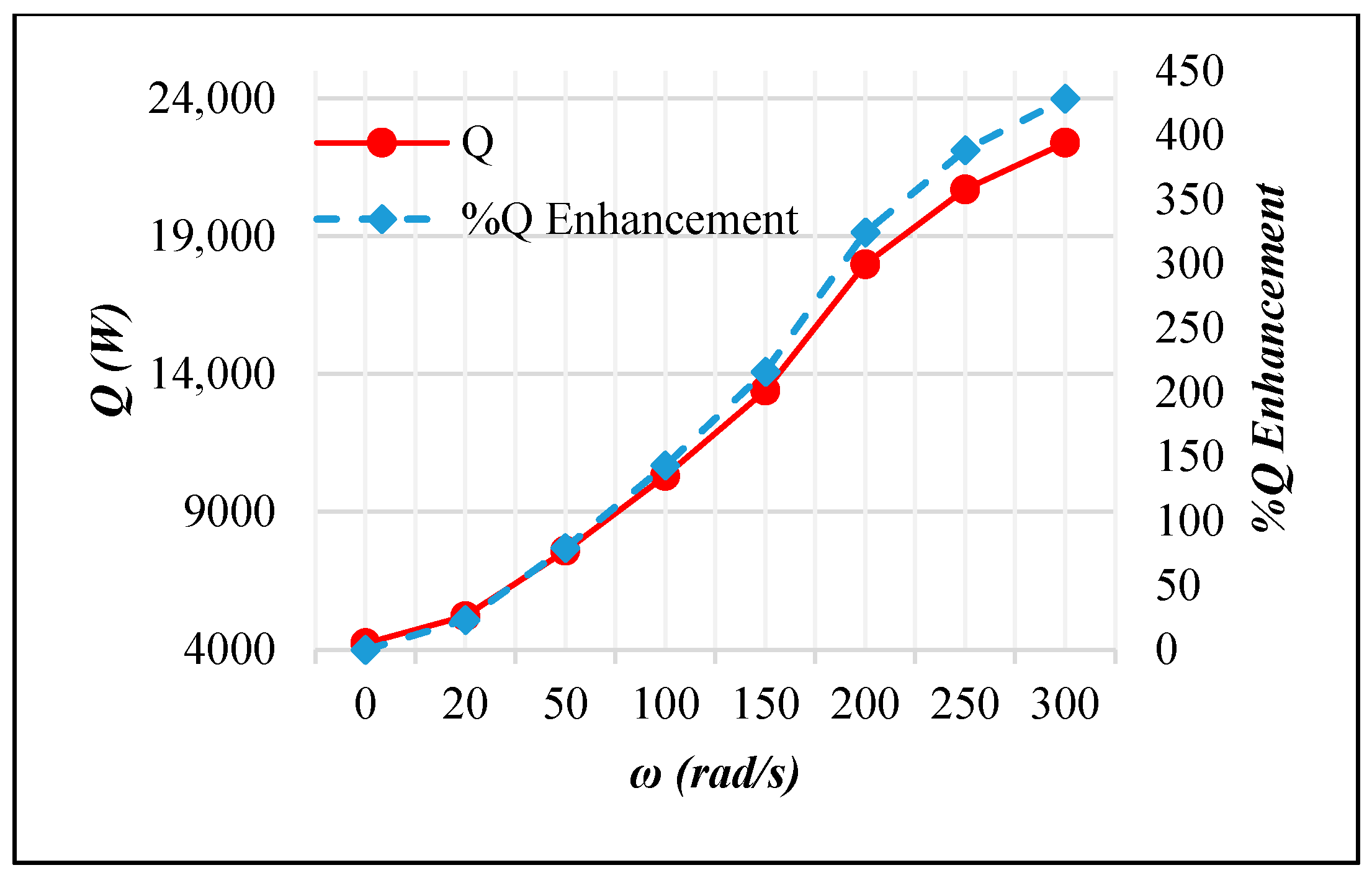
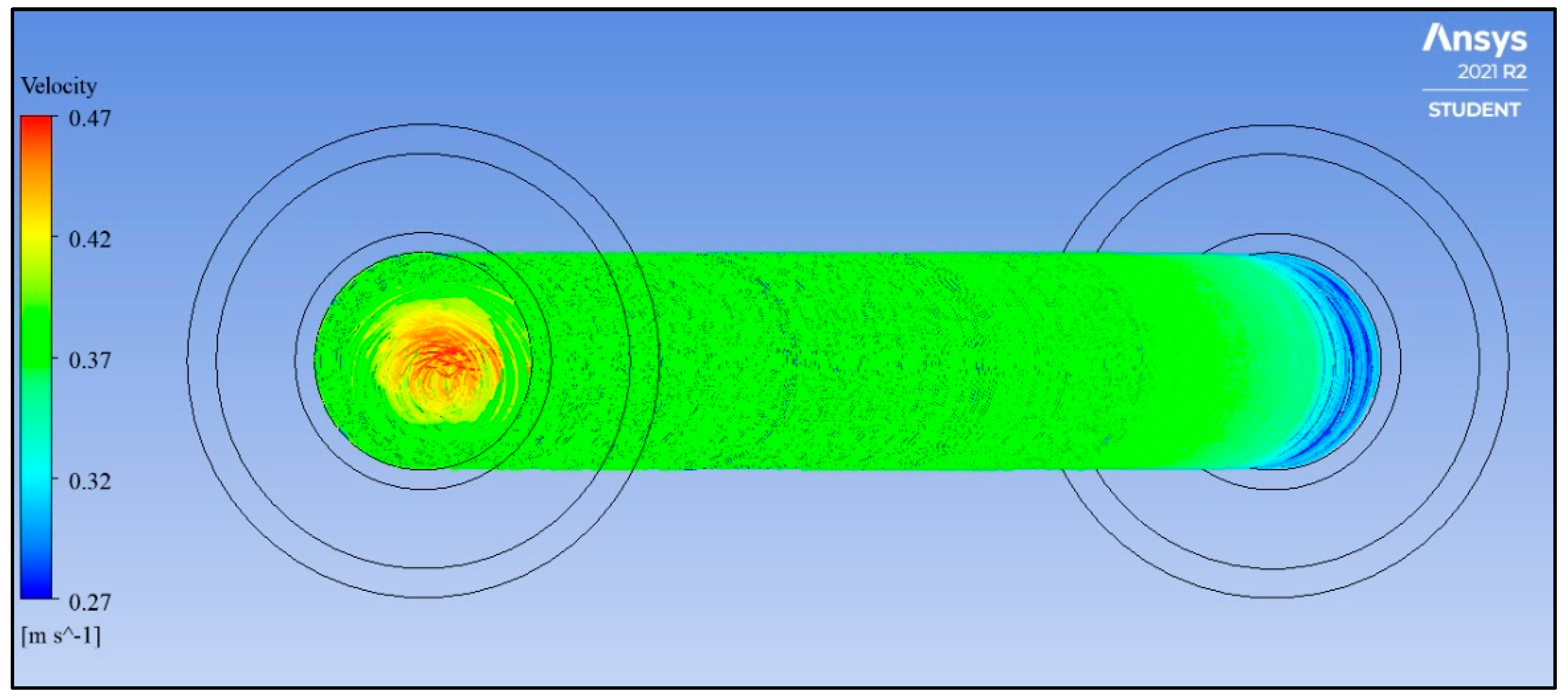
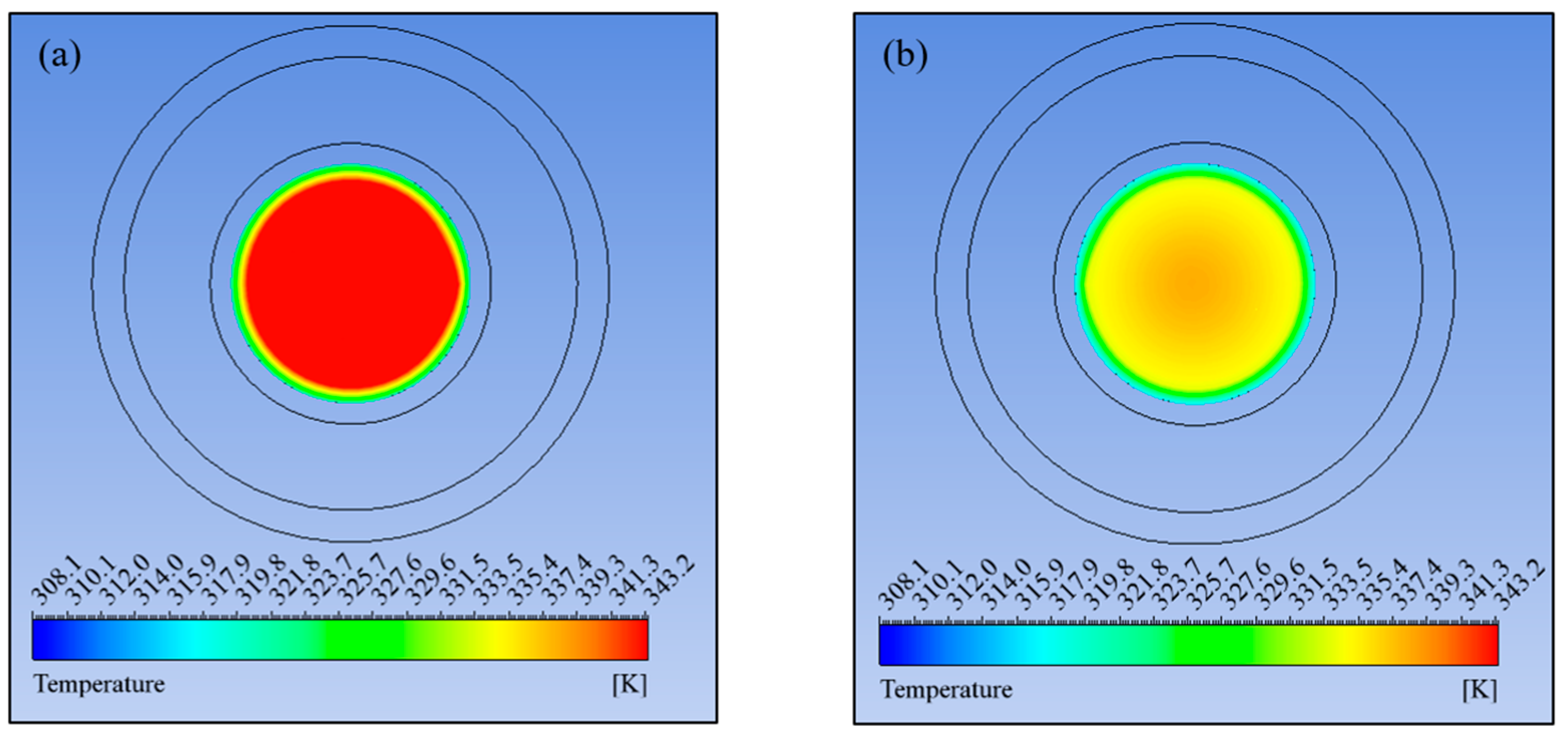
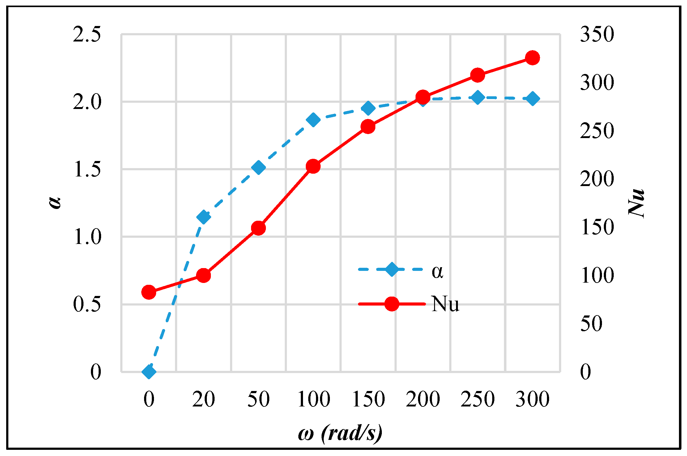
- Active AHT: Rotating the inner pipe up to 300 rad/s enhanced the heat transfer rate by 4.28 times. The thermal performance factor at this speed is 2.02, which was indicative of the AHT efficiency. Moreover, the pressure drop recorded was comparatively lower than the active and compound AHT methods performed.
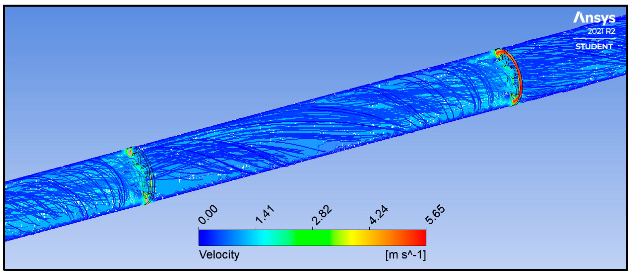
- Compound AHT: The rotation of inserts intensified swirls and vortices, resulting in rapid thermal mixing and a 47.5% improvement in heat transfer rate at 300 rad/s. The thermal performance factor is recorded at 0.80, indicating a better CCTHE effectiveness than the passive AHT.
In conclusion, all AHT techniques applied were capable in terms of enhancing the heat transfer rate of the CCTHE, with the active AHT (rotating inner pipe) resulting in the most efficient heat transfer.
This work recommends a further study on methods of lowering the pressure drop across the CCTHE caused by inserts. Additionally, a more comprehensive take on the cost analysis of inner pipe rotation active AHT is advised to prove its practical feasibility.
Author Contributions
Conceptualization, L.G.A.A. and B.D.J.; methodology, L.G.A.A.; software, L.G.A.A.; validation, L.G.A.A. and B.D.J.; formal analysis, L.G.A.A. and B.D.J.; investigation, L.G.A.A.; resources, L.G.A.A. and B.D.J.; data curation, L.G.A.A. and B.D.J.; writing—original draft preparation, L.G.A.A.; writing—review and editing, L.G.A.A. and B.D.J.; visualization, L.G.A.A. and B.D.J.; supervision, B.D.J. All authors have read and agreed to the published version of the manuscript.
Funding
The APC was funded by the Mapúa Institute for Creative and Research Opportunities (MICRO), Mapúa University, 658 Muralla St., Intramuros, Manila 1002, Philippines.
Institutional Review Board Statement
Not applicable.
Informed Consent Statement
Not applicable.
Data Availability Statement
The data presented in this study are available on request from the corresponding author, due to considerations regarding ongoing research works.
Acknowledgments
The authors would like to thank Mapúa University for providing the software. The authors also appreciate the support from the School of Graduate Studies and the School of Chemical, Biological, and Materials Engineering and Sciences, Mapúa University.
Conflicts of Interest
The authors declare no conflicts of interest.
References
- Begag, A.; Saim, R.; Abboudi, S.; Öztop, H.F. Effect of internal and external corrugated surfaces on the characteristics of heat transfer and pressure drop in a concentric tube heat exchanger. Int. J. Therm. Sci. 2021, 165, 106930. [Google Scholar]
- Kumar, V.; Sahoo, R.R. 4 E’s (Energy, Exergy, Economic, Environmental) performance analysis of air heat exchanger equipped with various twisted turbulator inserts utilizing ternary hybrid nanofluids. Alex. Eng. J. 2022, 61, 5033–5050. [Google Scholar] [CrossRef]
- Li, H.; Yang, X.; Wang, C.; Shi, S.; Ma, R.; Yuan, Y. Research and Application of Steam Condensation Heat Transfer Model Containing Noncondensable Gas on a Wall Surface. Appl. Sci. 2023, 13, 10520. [Google Scholar] [CrossRef]
- Li, H.; You, Z.; Zhang, H. Experimental investigation on the heat transfer enhancement of steam condensation on tube with hydrophilic-hydrophobic hybrid surface. J. Phys. Conf. Ser. 2022, 2280, 012059. [Google Scholar]
- Brodov, Y.M.; Aronson, K.E.; Ryabchikov, A.Y.; Nirenstein, M.A. Heat transfer augmentation during water steam condensation on twisted profile tubes. WIT Trans. Ecol. Environ. 2014, 190, 479–490. [Google Scholar]
- Ahmadi, S.; Eraghubi, M.; Akhavan-Behabadi, M.A.; Hanafizadeh, P.; Sayadian, S.; Robinson, A.J. EHD augmented heat transfer during upward bubbly flow boiling for low to medium frequency AC electric fields. Int. J. Therm. Sci. 2023, 191, 108346. [Google Scholar]
- Suri, A.R.S.; Pun, A.K.; Al Haque, M.S. Review of heat transfer augmentation methods and effect of using dimpled ribs and nanofluids. Mater Today Proc. 2022, 50, 830–836. [Google Scholar] [CrossRef]
- Nakhchi, M.E.; Hatami, M.; Rahmati, M. Experimental investigation of performance improvement of double-pipe heat exchangers with novel perforated elliptic turbulators. Int. J. Therm. Sci. 2021, 168, 107057. [Google Scholar]
- Nakhchi, M.E.; Esfahani, J.A.; Kim, K.C. Numerical study of turbulent flow inside heat exchangers using perforated louvered strip inserts. Int. J. Heat Mass. Transf. 2020, 148, 119143. [Google Scholar]
- Liu, P.; Zheng, N.; Shan, F.; Liu, Z.; Liu, W. Heat transfer enhancement for laminar flow in a tube using bidirectional conical strip inserts. Int. J. Heat Mass. Transf. 2018, 127, 1064–1076. [Google Scholar] [CrossRef]
- Keklikcioglu, O.; Ozceyhan, V. Experimental investigation on heat transfer enhancement in a circular tube with equilateral triangle cross sectioned coiled-wire inserts. Appl. Therm. Eng. 2018, 131, 686–695. [Google Scholar]
- Padmanabhan, S.; Yuvatejeswar Reddy, O.; Venkata Ajith Kumar Yadav, K.; Bupesh Raja, V.K.; Palanikumar, K. Heat transfer analysis of double tube heat exchanger with helical inserts. Mater. Today Proc. 2021, 46, 3588–3595. [Google Scholar] [CrossRef]
- Pandey, L.; Prajapati, H.; Singh, S. CFD study for enhancement of heat transfer and flow characteristics of circular tube heat exchanger using Y-shaped insert. Mater. Today Proc. 2021, 46, 9827–9836. [Google Scholar]
- Alam, T.; Kim, M.H. A comprehensive review on single phase heat transfer enhancement techniques in heat exchanger applications. Renew. Sustain. Energy Rev. 2018, 81, 813–839. [Google Scholar] [CrossRef]
- Thapa, S.; Samir, S.; Kumar, K.; Singh, S. A review study on the active methods of heat transfer enhancement in heat exchangers using electroactive and magnetic materials. Mater. Today Proc. 2021, 45, 4942–4947. [Google Scholar] [CrossRef]
- Al-Kouz, W.; Aissa, A.; Suriya Uma Devi, S.; Prakash, M.; Kolsi, L.; Moria, H.; Jamshed, W.; Younis, O. Effect of a rotating cylinder on the 3D MHD mixed convection in a phase change material filled cubic enclosure. Sustain. Energy Technol. Assess. 2022, 51, 101879. [Google Scholar]
- Tombrink, J.; Jockenhöfer, H.; Bauer, D. Experimental investigation of a rotating drum heat exchanger for latent heat storage. Appl. Therm. Eng. 2021, 183, 116221. [Google Scholar]
- Hosseinian, A.; Meghdadi Isfahani, A.H. Experimental study of heat transfer enhancement due to the surface vibrations in a flexible double pipe heat exchanger. Heat Mass Transf./Waerme- Und Stoffuebertragung 2018, 54, 1113–1120. [Google Scholar]
- Promvonge, P.; Eiamsa-ard, S. Heat transfer behaviors in a tube with combined conical-ring and twisted-tape insert. Int. Commun. Heat Mass Transf. 2007, 34, 849–859. [Google Scholar]
- Afsharpanah, F.; Ajarostaghi, S.S.M.; Hamedani, F.A.; Pour, M.S. Compound Heat Transfer Augmentation of a Shell-and-Coil Ice Storage Unit with Metal-Oxide Nano Additives and Connecting Plates. Nanomaterials 2022, 12, 1010. [Google Scholar] [CrossRef] [PubMed]
- Louahdi, M.; Salhi, J.E.; Essaouini, H.; Zarrouk, T.; Lahlaouti, M.L. Three-dimensional analysis for optimizing thermo-hydrodynamic performance of heat exchangers with perforated semi-circular inserts. Case Stud. Therm. Eng. 2024, 60, 104611. [Google Scholar] [CrossRef]
- Despotovic, M.; Nedic, V.; Despotovic, D.; Cvetanovic, S. Evaluation of empirical models for predicting monthly mean horizontal diffuse solar radiation. Renew. Sustain. Energy Rev. 2016, 56, 246–260. [Google Scholar] [CrossRef]
- Hangi, M.; Rahbari, A.; Lipiński, W. Design improvement of compact double-pipe heat exchangers equipped with tube-side helical insert and annulus-side helical strip: Hydrothermal and exergy analyses. Appl. Therm. Eng. 2021, 190, 116805. [Google Scholar] [CrossRef]
- Pourahmad, S.; Pesteei, S.M.; Ravaeei, H.; Khorasani, S. Experimental study of heat transfer and pressure drop analysis of the air/water two-phase flow in a double tube heat exchanger equipped with dual twisted tape turbulator: Simultaneous usage of active and passive methods. J. Energy Storage 2021, 44, 103408. [Google Scholar] [CrossRef]
- Maradiya, C.; Vadher, J.; Agarwal, R. The heat transfer enhancement techniques and their Thermal Performance Factor. Beni-Suef Univ. J. Basic Appl. Sci. 2018, 7, 1–21. [Google Scholar] [CrossRef]
- Ali, M.A.M.; El-Maghlany, W.M.; Eldrainy, Y.A.; Attia, A. Heat transfer enhancement of double pipe heat exchanger using rotating of variable eccentricity inner pipe. Alex. Eng. J. 2018, 57, 3709–3725. [Google Scholar] [CrossRef]
Disclaimer/Publisher’s Note: The statements, opinions and data contained in all publications are solely those of the individual author(s) and contributor(s) and not of MDPI and/or the editor(s). MDPI and/or the editor(s) disclaim responsibility for any injury to people or property resulting from any ideas, methods, instructions or products referred to in the content. |
© 2025 by the authors. Licensee MDPI, Basel, Switzerland. This article is an open access article distributed under the terms and conditions of the Creative Commons Attribution (CC BY) license (https://creativecommons.org/licenses/by/4.0/).