Article

Evaluation of the Fluid Properties Modification Through Magnetic Fields for Their Application on Tuned Liquid Dampers: An Experimental Approach

by
Andrea Vázquez-Greciano
,
César De Santos-Berbel
*,
Antonio Aznar López
and
Jesús M. Ortiz Herrera
Departamento de Estructuras y Física de Edificación, Universidad Politécnica de Madrid, 28040 Madrid, Spain
*
Author to whom correspondence should be addressed.
Appl. Sci. 2025, 15(8), 4194; https://doi.org/10.3390/app15084194
Submission received: 20 February 2025 / Revised: 1 April 2025 / Accepted: 9 April 2025 / Published: 10 April 2025

Abstract

:

Featured Application

Tuned Liquid Dampers exploit the sloshing motion of a contained liquid to counter vibrations in structures.

Abstract

Tuned Liquid Dampers (TLDs) are dissipative devices that mitigate vibrations through the out-of-phase movement of a fluid, typically water, inside a container relative to a main structure. Water’s low density and viscosity have led to modifications to enhance their effectiveness. Fluid properties, such as density or viscosity, significantly impact their performance by altering mass and damping, respectively. When magnetorheological fluids are employed, magnetic fields can modify the fluid viscosity, affecting the damping. This study experimentally examines the effect of a magnetic field and ambient parameters on the viscosity of different low-cost, custom-prepared magnetic fluids. A tube filled with magnetic liquids into which diverse non-magnetic spheres are dropped was employed, considering on- and off-states of the magnetic field generated by a pair of Helmholtz coils. The impact on the fluid viscosity variation of different measured variables was statistically analyzed. It was found that in all cases, the variations in ambient temperature and relative humidity had no effect on the results. While the magnetic field had a large effect on the viscosity of the magnetic fluid, for the sunflower oil-based fluids, the spheres used or the concentration of iron filings had a greater effect on the viscosity than the presence of the magnetic field.

1. Introduction

Structures can experience vibrations from different sources, including everyday use, such as pedestrians walking on bridges or vehicles crossing them, fluid/structure interaction effects, which can be derived from wind flow, or infrequent events, such as earthquakes or explosions. Depending on the source and nature of the vibrations, different mitigation strategies are applied, using damping devices and tailored approaches [1].
One strategy to mitigate vibrations is the use of Dynamic Vibration Absorbers, which rely on the out-of-phase movement of a mass with respect to the structure they are attached to. The secondary mass adds one degree of freedom to the system, thus modifying its natural frequencies. This kind of device was originally proposed by Frahm at the beginning of the 20th century [2]. The well-known Tuned Mass Dampers and Tuned Liquid Dampers are further developments belonging to this category. Traditional dampers are limited by their fixed damping characteristics, which can be suboptimal for structures subjected to varying excitation frequencies and amplitudes. On the contrary, Tuned Liquid Dampers (TLDs) are emerging as versatile devices designed to mitigate structural vibrations. These systems are cost-effective, require minimal maintenance, can be designed for temporary or permanent installations, and offer multidirectional and multifrequency applications, making them a promising solution to modern vibration control challenges [3]. These dissipative devices are based on the out-of-phase movement of a fluid, typically water, inside a container relative to the main structure to which they are attached. Over the last 50 years, different modifications on their shape, arrangement, or fluid used for improved functioning have been discussed [3]. Traditional TLDs are limited by their fixed damping characteristics, which can be suboptimal for structures subjected to varying excitation frequencies and amplitudes. Their inherently low damping ratio (approximately 0.5%) further underscores the need for supplementary mechanisms to enhance energy dissipation and improve performance [4]. Incorporating smart materials into TLDs offers a way to passively or semiactively enhance their performance. While these passive control systems are widely used because of their reliability (they activate automatically and need no power supply) [5], semiactive TLDs are attractive control systems because they can adjust their mechanical properties (i.e., when smart fluids are applied) based on real-time measurements of the structural response [6].
The development and optimization of TLDs rely heavily on experimental research. Testing hypotheses through controlled experimentation allows researchers to evaluate how design variables influence performance and identify ways to enhance efficiency. Additionally, experimental validation bridges the gap between theoretical models and real-world applications, ensuring accurate predictions of device behavior under dynamic loads, such as wind or seismic activity [7]. This dual approach of design exploration and validation is critical for advancing TLD technology and ensuring its reliability in practical applications.
This study explores the potential of TLDs with magnetic fields for passive and semi-active enhanced vibration control. The research aims to provide a practical background for the development of magnetic TLDs for future breakthroughs in this technology. Magnetorheological fluids (MRFs) are a kind of field-responsive fluid formed by suspensions of magnetic particles in a liquid that exhibit rapid and reversible increases in viscosity upon the application of a magnetic field [8]. When exposed to a magnetic field, the particles align to form chain-like structures along the field lines, significantly increasing the fluid’s apparent viscosity and altering its mechanical properties. This unique behavior makes MR fluids highly versatile for applications requiring precise control of damping and stiffness. MRFs have been applied in different fields, such as building and civil engineering or in the automotive and aerospace industries [9,10,11,12], with the use of adaptive shock absorbers, vibration control systems, and haptic devices [13]. The use of smart fluids in these industries is mainly applied to devices whose operating principle is based on hydraulic dampers, where damping is generated by the pressure required to force a fluid through an orifice. However, the use of MRFs to improve the performance of TLDs has not been so widely investigated.
Moreover, while previous studies have explored the use of MRFs in vibration control applications, most rely on commercial formulations with predefined properties and high production costs. In contrast, this study investigates the feasibility of using acrylic gel and custom-prepared magnetic fluids as a more accessible alternative. By employing commonly available materials such as sunflower oil and iron filings, we assess the extent to which these fluids can be tuned under an applied magnetic field to modify their viscosity. This approach not only provides insight into the adaptability of low-cost magnetic fluids for damping applications but also contributes to the broader understanding of how material composition and field intensity influence their rheological behavior. Moreover, the effect on viscosity of different ambient parameters, i.e., temperature and relative humidity, has been included in this work to determine whether the variation of these parameters influences the results.

2. Background

2.1. Experiments in Structural Vibration Control

Experiments with TLDs are particularly important in the field of structural vibration control for several reasons. First, the behavior of TLDs is typically modeled using fluid dynamics and vibration theory. Second, TLDs often exhibit nonlinear behavior due to fluid sloshing, which can be difficult to predict accurately using purely analytical methods. Experiments help identify and account for these nonlinearities, improving control strategies and damper design [14]. In addition, experimental studies allow engineers to optimize key parameters, such as the size, shape, and placement of TLDs, ensuring maximum vibration suppression for specific structures. These experiments help refine the design to achieve greater efficiency [15]. Furthermore, experiments replicate real-world conditions (such as wind, earthquakes, and other dynamic forces), helping to assess how TLDs perform under actual loading scenarios. This is critical for ensuring safety and stability in applications like tall buildings or bridges [16]. Testing new technologies, like the integration of MRFs in TLDs, requires experiments to validate how these innovations enhance performance, offering active or semi-active control of vibrations [17].
Escalante–Martínez et al. [18] proposed an experimental design to analyze the viscous damping coefficient in a mass/spring/damper system using different fluids such as water, edible oil, and motor oil. By observing the free decay of a mass submerged in the fluids, the logarithmic decrement of the response is measured, allowing for the determination of the damping coefficient. Their findings confirm that the damping coefficient increases with fluid viscosity, demonstrating a clear relationship between viscosity and energy dissipation. The inclusion of vegetable-based oil aims to evaluate its performance as an alternative to petroleum-derived lubricants due to its renewable nature and high biodegradability, which make it a promising option in sustainable engineering applications.
To investigate the impact of magnetic fields on the fluid viscosity and, consequently, on its damping, a uniform and controlled magnetic field is required. The Helmholtz coil is a pair of identical coils placed symmetrically and separated by a distance equal to the radius of the coils. This specific arrangement, in which the current flows in the same direction on both coils, produces a nearly uniform magnetic field in the region between the coils, making them ideal for practical experimentation and analysis. This principle relies on the Biot–Savart law and the superposition of magnetic fields [19].
The viscosity of ferromagnetic fluids varies with the strength and orientation of an applied magnetic field, depending on the ratio of hydrodynamic stress to magnetic stress [20]. For low ratios, viscosity is field-dependent, while at high field values, it becomes field-independent. Ohno et al. [21] devised a cylindrical container-tuned magnetic fluid damper and studied the effects of varying the depth of the magnetic fluid and the applied magnetic field on the damper’s performance. It was found that the presence of magnetic fluid significantly suppresses vibrations, especially near the natural frequency of the structure.

2.2. Measurement of Viscosity

The viscosity of a fluid can be measured through the falling-sphere method, where a sphere of known size and density is dropped into a fluid [22]. The motion of a sphere falling through a viscous fluid in a tube is governed by several forces, primarily gravity, buoyancy, and viscous drag [23]. The forces acting on a sphere of radius r are depicted in Figure 1. The dynamics are described using Stokes’ law and the equations of motion for the sphere. It must be noted that for the description of the system, laminar flow, isotropic and Newtonian fluid with constant properties is assumed. Given the experimental approach conducted in this work, it is worthwhile mentioning that classical Stokes laws do not account for potential nonlinear effects that may arise at high concentrations of the ferromagnetic particles included in the carrier fluids, or anisotropies in the magnetic field applied. Therefore, the validity of these equations is primarily limited to conditions where the concentration of ferromagnetic particles is low enough to minimize collective interactions and nonlinear effects and when the applied magnetic field remains uniform.
The gravitational force acting on the sphere is given by:
F g = m · g = V · ρ s · g
where V is the volume of the sphere, ρ s is the density of the sphere, and g is the acceleration due to gravity. The volume of the sphere is calculated according to the equation:
V = 4 3 · π · r 3
The buoyant force is the upward force exerted by a fluid on an object that is either partially or fully submerged in it. This force occurs because of the pressure difference between the top and bottom of the object caused by the fluid’s weight. It is given by the equation:
F b = V · ρ f · g
where ρ f is the density of the fluid.
The viscous drag force is the resistive force exerted by the fluid on the sphere moving through it. This force is a result of the viscosity of the fluid, which is a measure of its resistance to flow or deformation. The viscous drag opposes the motion of the object and increases with the object’s speed and the fluid’s viscosity. For low Reynolds numbers ( R e < 1 ), the viscous drag of a sphere submerged in the fluid is given by Stokes’ law:
F d = 6 · π · η · r · v
where η is the dynamic viscosity of the fluid, and v is the velocity of the sphere. The viscosity of a fluid can be experimentally determined [23].
The equation of motion of the sphere is governed by the net force acting on it, which, in turn, determines its acceleration.
F g F b F d = m · d v d t
Substituting the forces:
V · ρ s · g V · ρ f · g 6 · π · η · r · v = V · ρ s · d v d t
The sphere submerged in a viscous fluid reaches a terminal velocity, which is the constant speed it achieves when the net force acting on it is zero and, therefore, the acceleration equals zero. This occurs when the downward gravitational force is exactly balanced by the upward buoyant force and the resistive viscous drag force:
v t = 2 r 2 · ρ s ρ f · g 9 · η
This equation shows that the terminal velocity increases with the square of the radius of the sphere, with the difference in density between the sphere and the fluid and with the inverse of the viscosity of the fluid.
Before reaching terminal velocity, the motion can be described by the following expression:
ρ s · d v d t = ρ s ρ f · g 6 · π · η · r V v
Substituting the term of the volume of the sphere, operating and simplifying further:
d v d t + 9 · η 2 ρ s · r 2 v = ρ s ρ f · g ρ s
The term that accompanies the velocity v can be renamed as τ . This is a first-order linear differential equation. Using an integrating factor or solving directly, the velocity v ( t ) is:
v ( t ) = v 0 + v t 1 e t / τ
where v 0 is the initial speed. Ideally, the sphere approaches the terminal velocity asymptotically rather than reaching it exactly in finite time. This behavior arises from the exponential term in the velocity equation over time.
From this expression it can be derived that whether the body immersed in the fluid is in force equilibrium or subjected to a non-zero force resulting, the viscosity of the fluid is lower and the faster the movement. Altering the viscosity of the fluid at will would create an effective damper to cope with the vibrations to which a structure may be subjected. Therefore, the activation of a magnetic field is a strategy of great interest in the design of vibration control systems.
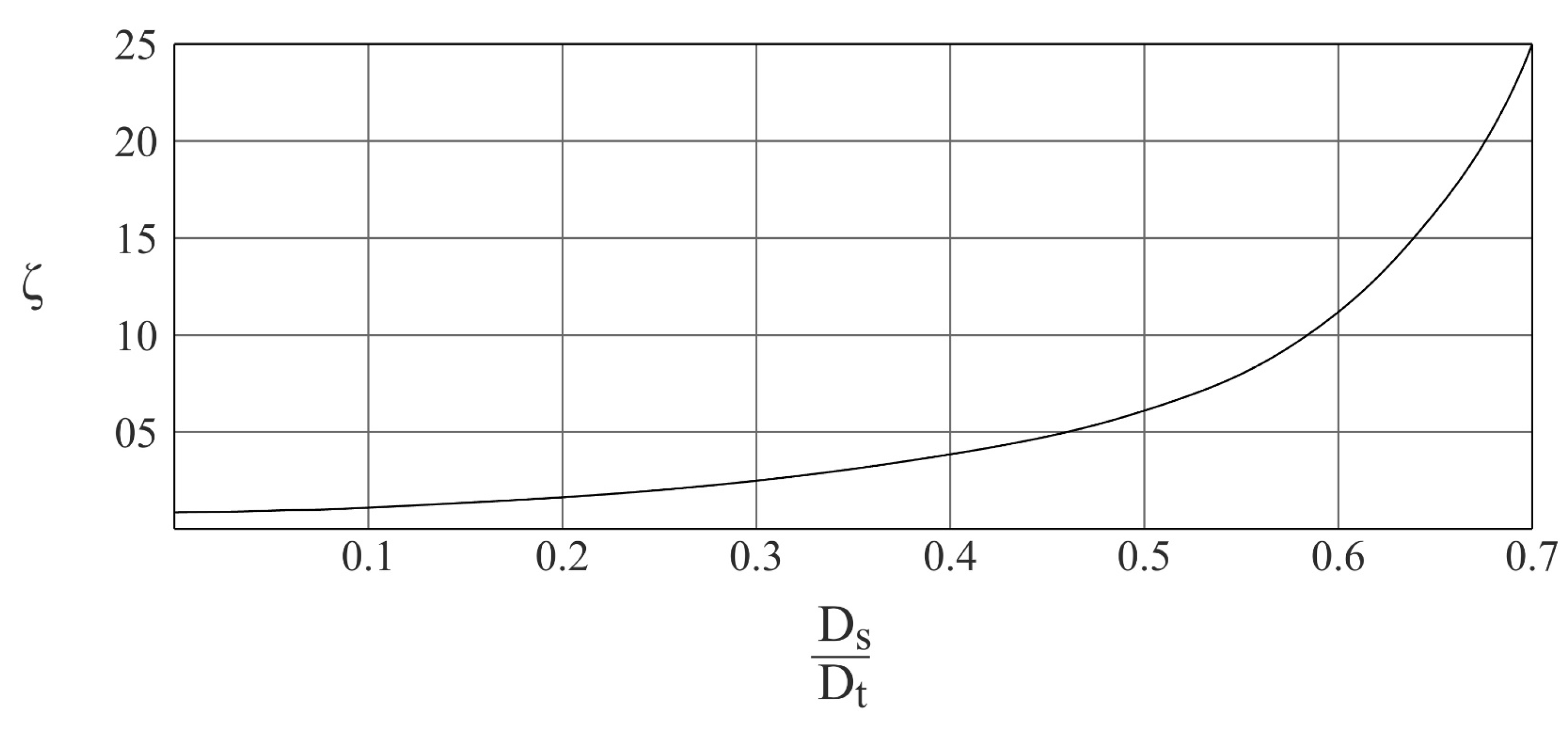
It must be noted that this procedure considers that the sphere has a low velocity profile and that its diameter is small with respect to the diameter of the tube, given by a value of the ratio in Equation (11) equal to or lower than 0.2.
ζ = D s D t
where D s corresponds to the diameter of the sphere and D t represents the diameter of the tube. For greater ratios, a correction factor ( ζ ) obtained from Figure 2 can be included in Equation (12), resulting in:
η = 2 r 2 · ρ s ρ f · g 9 · v · ζ  
The density of the fluid analyzed can be obtained experimentally if the respective velocities of two spheres of different properties are measured. Given that the fluid dynamic viscosity remains constant for different falling spheres, equating the right-hand side of Equation (12) for the two cases considered retrieves:
D s 1 2 · ρ s 1 ρ f v 1 · ζ 1   = D s 2 2 · ρ s 2 ρ f v 2 · ζ 2  

2.3. Helmholtz Coils

Magnetic fluids offer a unique ability to dynamically adjust their viscosity in response to external magnetic fields. The application of a magnetic field to the ferrofluid provides precise control over its rheological properties but requires a reliable method to generate the field. Moving electric charges, such as an electric current through a conductor, generate a magnetic field as described by Ampere’s Law. Particularly, the components involved in the magnetic field created by an electric current I flowing through a coil at a generic point P are displayed in Figure 3.
The magnetic field at the point P produced by the electric current I along an infinitesimal length d l is given by the Biot–Savart law [24]:
d B = μ 4 · π · I · d l × u r r 2
where μ is the permeability of the medium in which the point P is immersed. The sum of the contributions d B is obtained by integrating around the complete spire:
B = μ · I 4 · π d l × u r r 2
A Helmholtz pair consists of two identical circular coils, symmetrically positioned along a shared axis on either side of the experimental region. The coils are separated by a distance equal to the radius R of each coil, and both carry the same electric current flowing in the same direction. Figure 4 shows the disposition of the parallel coils along with the magnetic field created in the horizontal plane z = 0 by a current flowing through the coils in the same direction. The Helmholtz arrangement results in a nearly uniform magnetic field between the two coils, where the magnetic field created is much more intense, as shown by the length of the arrows, where the cylinder containing the liquid is placed along a vertical axis. This allows for modification of the rheologic features of the liquid.

2.4. Ferrofluid Behaviour

The viscosity of a magnetic fluid, or ferrofluid, varies significantly under the influence of a magnetic field. This variation is due to the alignment and interaction of the magnetic nanoparticles suspended in the carrier fluid [25]. The increase in viscosity under a magnetic field enhances the energy dissipation capacity of the fluid, making it more effective in controlling oscillations. By altering the strength of the magnetic field, the viscosity of the fluid can be dynamically tuned, allowing the TLD to respond to varying vibration amplitudes and frequencies in real-time.
In the absence of a magnetic field, the nanoparticles are randomly distributed and move freely within the fluid. Viscosity primarily depends on the base carrier fluid and the concentration of magnetic particles. The fluid behaves as a Newtonian fluid (constant viscosity, independent of shear rate) under low particle concentrations [26].
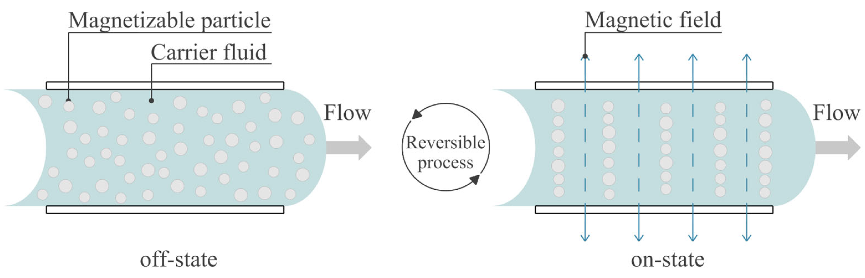
When a magnetic field is applied, three effects occur. First, the magnetic nanoparticles align along the magnetic field lines [27]. This alignment can increase the internal resistance to flow, effectively increasing the viscosity of the fluid. Second, at higher field strengths, the particles may form chains or structures along the field lines. These structures disrupt the fluid flow, leading to a significant increase in viscosity. In some cases, the fluid can exhibit non-Newtonian behavior, with the viscosity depending on the shear rate [28,29]. Third, the dependence of viscosity on the strength of the applied magnetic field is known as the magnetoviscous effect. This relationship is typically nonlinear: small increases in field strength can cause significant changes in viscosity [30]. These effects occur when the magnetic field is activated, also known as the on-state. The chain-like arrangement is a reversible process, and particles flow freely when the magnetic field is no longer activated (off-state). This behavior is depicted in Figure 5.
Several factors affect how viscosity changes under a magnetic field. Higher particle concentrations lead to more pronounced viscosity changes, while larger particles or broader size distributions can enhance alignment and chain formation. Stronger magnetic fields cause more alignment and structure formation. Higher temperatures can reduce the effect of the magnetic field due to increased thermal agitation. The properties of the carrier fluid also influence the overall magnetoviscous behavior. It must be noted that the temperature alone is a parameter that can significantly alter the fluid viscosity, depending on its specific properties. For this reason, in this work the temperature has been controlled throughout the tests and has been included in the analysis to account for its potential influence on viscosity variation.
Several authors have investigated the dependence of magnetic fluid viscosity on external magnetic fields, employing both theoretical and experimental approaches. Shen and Doi [31] calculated the effective viscosity of magnetic fluids at the particle scale. They compared their results with classical constitutive equations and proposed a new equation according to their numerical findings. Patel [32] investigated the simultaneous effects of magnetic field and temperature on the capillary viscosity of magnetic nanofluids. The study provided experimental data and proposed theoretical explanations for the observed changes in effective viscosity under varying magnetic field strengths and orientations. Additionally, Patel et al. [33] measured the effective viscosity of a ferrofluid as a function of an applied magnetic field oriented perpendicular to the capillary flow. Their findings showed close agreement with the Shliomis [34] expression, derived using the effective field method, providing insights into how the viscosity changes with varying magnetic field strengths. Polunin et al. [35] estimated the viscosity increment in a magnetic fluid column oscillating under a strong transverse magnetic field. The authors calculated viscosity using expressions derived from different theoretical approaches and analyzed the impact of the magnetic field on the fluid’s viscosity.

3. Experimental Setup

The experiments were conducted on a graduated cylinder, as depicted in Figure 6, and filled with different liquids. The diameter of the tube was 61 mm. The magnetic fields were created by connecting Helmholtz coils to a DC battery, which provides a voltage of 12 V. The axis of the coils was arranged horizontally, and the tube was placed between the coils (Figure 6). Then, a sphere was gently deposited at the top surface of the liquids to descend along the tube by the action of gravitational force. Two positions were marked on the tube to monitor the fall of the sphere, defining a constant distance of 0.2 m. The time elapsed between reaching the first mark and the second mark was measured. The fluid, being transparent, allows observing the fall of the sphere and determining the moment of passage through the reference marks, as well as the absence of events that may invalidate the experiment, such as a collision with the walls of the tube. All attempts where the sphere brushed or hit the wall of the tube were discarded. All the tests were conducted under strict monitoring of the environmental conditions, namely environment temperature, relative humidity, and the temperature of the liquid in the tube, to ensure that the possible variations in the viscosity were not related to changes in these variables.

3.1. Characterization of Tests with Magnetic Fluid

A clear acrylic gel was used in the first set of tests, as shown in Figure 6. It is a commercially available transparent conductive gel widely used in the sanitary industry. It is visibly viscous and conducts electrowaves. This kind of water-based fluid presents a density similar to water (approx. 1000 kg/m3 ± 0.5%), and its dynamic viscosity typically ranges from 30 to 180 kg/s/m. A lead sphere with a diameter of 38 mm and a mass of 0.313 kg was prepared for the test (Sphere 1 in Table 1). This material was selected for its high density and non-magnetic properties.

3.2. Characterization of Tests with Sunflower Oil

In the second set of trials, a ferromagnetic emulsion was prepared with available low-cost materials. The carrier fluid was sunflower oil, which was used alone in certain trails and to which iron filings obtained by grinding were added in others.
Sunflower oil is employed as a base fluid to evaluate its feasibility for the custom preparation of MRFs, aligning with the low-cost approach considered in this study. This fluid represents an example of a liquid whose viscosity varies significantly with the temperature [36,37,38,39,40,41,42,43], as represented by Figure 7. In the range of temperatures considered in this study (11.63–17.4 °C), the dynamic viscosity of sunflower oil ranges from η = 0.095 kg/s/m to η = 0.072 kg/s/m.
The particle size of the iron fillings was smaller than 0.1 mm. Following the experiments by Mesquida and Lässig [44], iron fillings and oil were mixed with a weight ratio of magnetic particles-to-liquid volume of 0.0128 g/mL. Since this percentage did not permit a clear vision of the sphere flowing through the fluid, the mixture was diluted until it could be assured that the tracking of the spheres was guaranteed, resulting in a proportion of 1/10 of the initial ratio, i.e., 0.00128 g/mL. The sedimentation of particles over time could be observed through visual inspection. To ensure the highest possible homogeneity of particle dispersion, the mixture was stirred before the start of each test. Two glass spheres (Sphere Ids 2 and 3 in Table 1) and one plastic sphere (Sphere Id 4 in Table 1) were utilized to drop into this fluid, which is less viscous than the acrylic gel. These spheres also featured non-magnetic properties in order to not interfere with the magnetic field generated and have a lower density than the lead sphere. Their masses and diameters were measured, and the resulting densities were verified.

3.3. Magnetic Field

A pair of parallel coils was placed around the tube following the Helmholtz setup to create a constant magnetic field perpendicular to the direction of the spheres falling in the graduated cylinder, located in the intermediate zone of the section where the passing time is measured. According to the low-cost approach of this work, the pair of coils was obtained from the engine of a washing machine. The copper wires have a circular cross-section of 0.6 mm diameter. The coils are arranged in a rectangular pattern with rounded corners. Their dimensions are 93 mm high, 68 mm wide, and 9 mm thick, as shown in Figure 8. Each coil has a 14 mm copper wire bundle. They are connected in series to a 12 V battery that provides direct current, ensuring that the direction of the current flow is the same in both coils to generate a homogeneous magnetic field in the region between the coils. The magnitude of the magnetic field is measured by means of a transverse probe Gaussmeter. The final setup considers a distance between the center of the coils of 0.085 m, which generates a magnetic field of 0.015 T at the midpoint of the coil axes when immersed in air.

3.4. Tracking of the Spheres

The motion of the spheres was recorded with the camera of a smartphone located at a fixed distance of 1 m from the tube, right in front of the measurement zone. The resolution of the videos was 1920 × 1080 pixels, and the frame speed was 240 frames per second. The videos recording the falling of the spheres were analyzed using the open-source software Tracker (version 6.2.0) [45], in which the position of the sphere is registered for each frame. This allows determining their velocity considering the time registering their passage through the initial and final marks on the tube, located 20 cm apart. First, the distances were calibrated in the image by means of 1 × 1 cm calibration markers located on the graduated cylinder, depicted in Figure 8, and the coordinate axes were located to ensure a proper measurement, as represented in Figure 9. The reference point from which the position measurements were made was the bottom of the spheres. The software provides graphs that display the displacement of the sphere with respect to time so the position, speed, and acceleration can be retrieved (Figure 9).

4. Analysis of Results

4.1. Factors Affecting the Viscosity of the Magnetic Fluid

In the first set of trials, elapsed times Δ t of Sphere 1 between the two marks through the magnetic fluid without activating the magnetic field were measured. The statistics of the measurements are displayed in Table 2. The ambient temperature was kept between 23.4 and 23.7 °C during the test. Pearson’s correlation between the ambient temperature and the elapsed times was examined to assess whether the temperature affected the motion of the sphere. The correlation coefficient was −0.029, and the corresponding p-value was 0.936, indicating that the null hypothesis that considers that the temperature did not significantly affect the motion is true. Similarly, Pearson’s correlation between the relative humidity and the elapsed times was studied to assess whether the humidity affected the motion of the sphere. The correlation coefficient was −0.075, and the associated p-value was 0.838, indicating that the null hypothesis that the relative humidity did not significantly affect the motion of the sphere is true, which allows completely ruling out the influence of humidity on the motion of the sphere.
In the second set of trials, elapsed times Δ t of Sphere 1 between the two marks through the magnetic fluid with an active magnetic field were measured. The statistics of such measurements are shown in Table 3. The ambient temperature varied between 26.6 and 26.7 °C during the test. Pearson’s correlation between the ambient temperature and the elapsed times was examined to verify whether the temperature affected the motion of the sphere. The correlation coefficient in this case was 0.053, and the corresponding p-value was 0.910, showing that the temperature did not significantly affect the motion of the sphere. Next, Pearson’s correlation between the relative humidity and the elapsed times was studied to evaluate whether the temperature affected the motion of the sphere. In this particular case, the relative humidity remained constant, so it is not possible to determine if an association exists.
To verify the effect of the magnetic field on the motion of the sphere through the magnetic fluid, a t-test for non-paired samples was performed to check the null hypothesis that the samples come from the same two underlying populations and have the same mean value. If a two-sample equal variance is considered (i.e., homoscedastic), the test returned the p-value 0.0109. If a two-sample unequal variance (i.e., heteroscedastic), the test returned the p-value 0.0260. In both cases, the null hypothesis can be rejected at the 95% confidence level. This result indicates that the magnetic field effectively increases the viscosity of the fluid and may allow the design of devices for active vibration control and TLDs. Additionally, the viscosity of the magnetic fluid has been evaluated in Equation (12), considering that the terminal velocity was reached in the tests. The mean dynamic viscosity of the fluid results in 70.4 kg/s/m for the off-state and increases to a mean dynamic viscosity equal to 78.1 kg/s/m when the magnetic field is activated.
The results indicate that the viscosity of the fluid underwent significant modification under the influence of the magnetic field. However, the increased variability in the sample suggests a lack of satisfactory control over the viscosity of the fluid when the magnetic field is applied. This may be due to the trajectory of the sphere deviating slightly from the central axis of the tube rather than following an exact axial path from the outset. The random nature of the variance in the measurements is not to be discounted, and it is important to note that increased variability was observed with longer lapsed times measured with the active magnetic field. In relative terms, the differences in variability are smaller (with magnetic field 1.21/21.9 = 0.055, without magnetic field 2/25 = 0.08).

4.2. Factors Affecting the Viscosity of the Sunflower Oil

The second set of trials comprises those in which the spheres fell through both the sunflower oil and the ferromagnetic emulsion prepared with sunflower oil. The times Δ t were measured for Spheres 2, 3, and 4 to fall between the two marks through unmixed sunflower oil, sunflower oil with iron filings, and in the latter case, without activating the magnetic field and with an active magnetic field. Table 4 compiles the range of factor combinations in each test set and shows the counterpart measurement statistics. Lapse-time Δ t measurements include maximum value, minimum value, sample mean, and standard deviation. Ambient temperature statistics include sample mean, standard deviation, Pearson’s correlation coefficient with Δ t , and the corresponding p-value. Similarly, relative humidity statistics include sample mean, standard deviation, Pearson’s correlation coefficient with Δ t , and the corresponding p-value. The magnetic field was active in some cases in which sunflower oil was mixed with iron filings. In the case of Sphere 4, because it is white, it was possible to prepare a fluid with twice the concentration of iron filings that would allow the movement to be tracked. The indicated intensity of the magnetic field was measured, as described in Section 3.3. On the one hand, it can be observed that in some sets, the ambient temperature, or, more frequently, relative humidity, was constant throughout the trials. Therefore, there was no possible effect of these variables on the velocity of the falling sphere. In the remainder of the cases, variations in neither ambient temperature nor relative humidity had a significant effect on the movement of the sphere according to the p-value of the Pearson correlation coefficient when considering a 95% confidence interval according to the p-value obtained in the corresponding correlation estimations.
Once the influence of environmental factors in each of the phases of the experiment has been ruled out, statistical tests are carried out to analyze the overall view of the experiment with respect to the variables of interest: fluid characteristics, sphere characteristics, and magnetic field. Following Equation (12), an increment of the fluid viscosity occurs for slower terminal velocities, which correspond to longer values of Δ t , expected in the presence of a magnetic field. To account for all the factors in the experiments conducted with sunflower oil, a multifactorial ANOVA test with inter-subject effects was performed. The dependent variable was the lapse time Δ t , while the independent variables were the sphere, the concentration of iron filings, and the magnetic field intensity. The results of this analysis are presented in Table 5. Considering a 95% confidence level, the effects of the sphere and the concentration of iron filings were significant, while the magnetic field intensity was far from having a significant effect on the motion of the spheres.
The tracked series of the fall of Spheres 2 and 3 were fitted under all hypotheses to Equation (10) using least squares. The adjustment of the curves with an active magnetic field was performed only on the tracked points in the area of the coils. From the adjustment, the viscosity, the correction factor ζ, and the terminal velocity v t were deduced. The variability of the measurements can be obtained through the root mean square error (RMSE) of a fitted curve to the displacement vs. time plot. The overall RMSE in the fitted curves was 0.127 cm. Figure 10 shows one of the adjusted series of the fall of Sphere 3. The results are shown in Table 6.
A t-test was performed to compare the variations in dynamic viscosity and the correction factor across trials for each sphere. In the absence of an active magnetic field, both the variations in dynamic viscosity and the correction factor across trials for each sphere were not significant at the 95% confidence level. This indicates that the addition of iron filings had no substantial effect on either parameter. The measured dynamic viscosity values align with those reported in the literature (Figure 7). However, the correction factors obtained in this study are notably higher than those inferred from Figure 2, suggesting that the effective viscosity may depend not only on the sphere-to-tube diameter ratio but also on their absolute diameters.
The tracked series of the fall of Sphere 4 could not be successfully fitted since the sphere nearly reached the terminal velocity. Instead, Equation (7) was used to deduce the effective viscosity from the measured fall velocities. The results are shown in Table 7.
A t-test was performed to compare the variations in the terminal velocity and the dynamic viscosity across trials for Sphere 4. The measured terminal velocity decreases with the active magnetic field but not significantly at the 95% confidence level. A slight increase in dynamic viscosity is also observed, but the increase cannot be said to be significant either. The variation in observations can be attributed to the turbidity of the oil when iron filings are added, which makes it difficult to track the spheres.

4.3. Discussion

In the design of a TLD, the surface of the fluid must remain free; however, there is the possibility of air bubbles appearing inside the ferromagnetic fluid. This means that the fluid does not have homogeneous characteristics, and therefore, its behavior when the magnetic field is activated may not be as expected.
The preparation of a ferromagnetic fluid with the addition of iron filings presents significant sources of uncertainty. First, a large amount of iron filings is needed to obtain a significant increase in viscosity, which could turn the fluid into a semi-solid paste whose behavior, far from that of a fluid, may not be appropriate for the design of TLDs. Second, upon activation of the magnetic field, the iron filings could proceed to concentrate and arrange according to the field intensity if the field layout is not sufficiently homogeneous.

5. Conclusions

This study experimentally examined the effect of a magnetic field and ambient parameters on the viscosity of different low-cost, custom-prepared magnetic fluids for the design of TLDs. Experimental investigations are essential to validate theoretical models, refine design parameters, and ensure the effective performance of TLDs in mitigating structural vibrations under real-world conditions. These insights directly improve the safety and resilience of buildings and infrastructure. The coupling of magnetic fluids with magnetic field activation provides a versatile and efficient means of vibration control. The ability to dynamically adjust viscosity in response to structural demands makes this approach particularly promising for modern adaptive damping solutions.
The set of tests with magnetic acrylic gel demonstrated that this fluid modified its viscosity significantly under the magnetic field. However, the increased deviation in the sample indicated that there is no satisfactory control over the viscosity of the fluid when the magnetic field is active.
Despite the statistical tests that have shown that the temperature and the relative humidity were well controlled during the trials to eliminate their effects, slight variations in other experimental conditions have been shown to affect the variables to be measured, particularly the viscosity.
Regarding the set of experiments corresponding to the sunflower-based fluid, it was observed that the presence of the magnetic field did not significantly affect the viscosity of the ferromagnetic emulsion. Several factors can influence this behavior. First, the intensity of the magnetic field is crucial—small values may not be sufficient to modify the arrangement of the ferromagnetic particles in the fluid. Secondly, the concentration and homogeneity of the ferromagnetic particles play a key role. A low concentration was required to ensure proper tracking of the motion of the falling spheres, but at the same time may not be enough to ensure a strong chain formation in the presence of the magnetic field.
One of the key challenges identified in this study is the tendency of ferromagnetic particles to settle over time, affecting the homogeneity of the fluid and its rheological response under a magnetic field. To mitigate this issue, future research could explore the use of surfactants or stabilizing agents, such as nanoparticle coatings, to improve particle dispersion and prevent agglomeration. Furthermore, optimizing the particle size distribution and density could enhance suspension stability while maintaining effective viscosity modulation.
Another potential approach is the development of continuous agitation or periodic field activation strategies to counteract sedimentation. By periodically energizing the system with alternating magnetic fields, the fluid could be maintained in a more homogeneous state, ensuring consistent damping performance. Furthermore, the design of container geometries that promote uniform field exposure and fluid recirculation could also be investigated to improve long-term stability.
Addressing these challenges is critical for the practical implementation of magnetic-fluid-based TLDs. Future work in this direction could refine the feasibility of these systems and enhance their reliability in structural vibration control applications.
Future advances in magnetic fluid formulations and electromagnet technology could further enhance the feasibility and effectiveness of magnetic fluid-based TLD systems. Furthermore, challenges related to tracking accuracy due to oil turbidity highlight the need for more advanced monitoring techniques during experiments. Future work should also integrate real-time vibration monitoring to better assess the impact of magnetorheological effects in practical applications. Finally, the correction factor for the effective viscosity to account for the sphere-to-tube diameter ratio should be revised since the effective viscosity may also depend on the absolute diameter values.

Author Contributions

Conceptualization, A.V.-G., A.A.L. and J.M.O.H.; methodology, A.V.-G., A.A.L. and J.M.O.H.; software, A.V.-G.; validation, A.V.-G., C.D.S.-B., A.A.L. and J.M.O.H.; formal analysis, A.V.-G. and C.D.S.-B.; investigation, A.V.-G. and C.D.S.-B.; resources, A.V.-G. and A.A.L.; data curation, A.V.-G. and C.D.S.-B.; writing—original draft preparation, A.V.-G. and C.D.S.-B.; writing—review and editing, A.V.-G., C.D.S.-B., A.A.L. and J.M.O.H.; visualization, A.V.-G., C.D.S.-B., A.A.L. and J.M.O.H.; supervision, A.A.L. and J.M.O.H.; project administration, A.V.-G. and A.A.L.; funding acquisition, A.V.-G. All authors have read and agreed to the published version of the manuscript.

Funding

This research was funded by Universidad Politécnica de Madrid (Programa Propio de I+D+i 2019).

Institutional Review Board Statement

Not applicable.

Informed Consent Statement

Not applicable.

Data Availability Statement

The data that support the findings of this study are available from the corresponding author upon reasonable request.

Acknowledgments

A.V.-G. would like to acknowledge the support provided by the predoctoral contract Ayuda Programa Propio from the Universidad Politécnica de Madrid.

Conflicts of Interest

The authors declare no conflicts of interest.

References

  1. Kandasamy, R.; Cui, F.; Townsend, N.; Foo, C.C.; Guo, J.; Shenoi, A.; Xiong, Y. A Review of Vibration Control Methods for Marine Offshore Structures. Ocean Eng. 2016, 127, 279–297. [Google Scholar] [CrossRef]
  2. Frahm, H. Device for Damping Vibrations of Bodies. U.S. Patent US989958A, 18 April 1911. [Google Scholar]
  3. Vázquez-Greciano, A.; Aznar López, A.; Buratti, N.; Ortiz Herrera, J.M. Magnetic Fields to Enhance Tuned Liquid Damper Performance for Vibration Control: A Review. Arch. Comput. Methods Eng. 2024, 31, 25–45. [Google Scholar] [CrossRef]
  4. Konar, T.; Ghosh, A.D. Flow Damping Devices in Tuned Liquid Damper for Structural Vibration Control: A Review. Arch. Comput. Methods Eng. 2021, 28, 2195–2207. [Google Scholar] [CrossRef]
  5. Almajhali, K.Y.M. Review on Passive Energy Dissipation Devices and Techniques of Installation for High Rise Building Structures. Structures 2023, 51, 1019–1029. [Google Scholar] [CrossRef]
  6. Fisco, N.R.; Adeli, H. Smart Structures: Part I—Active and Semi-Active Control. Sci. Iran. 2011, 18, 275–284. [Google Scholar] [CrossRef]
  7. Abé, M.; Fujino, Y.; Kimura, S. Active Tuned Liquid Damper (TLD) with Magnetic Fluid. In Smart Structures and Integrated Systems, Proceedings of the 5th Annual International Symposium on Smart Structures and Materials, San Diego, CA, USA, 1–5 March 1998; SPIE: Bellingham, WA, USA, 1998; pp. 620–623. [Google Scholar]
  8. Ashour, O.N.; Kinder, D.; Giurgiutiu, V.; Rogers, C.A. Manufacturing and Characterization of Magnetorheological Fluids. In Smart Structures and Materials 1997: Smart Materials Technologies, Proceedings of the Smart Structures and Materials ‘97, San Diego, CA, USA, 3–6 March 1997; International Society for Optics and Photonics (SPIE): Bellingham, WA, USA, 1997; Volume 3040, pp. 174–184. [Google Scholar]
  9. Genc, S.; Derin, B. Field Responsive Fluids—A Review. Key Eng. Mater. 2012, 521, 87–99. [Google Scholar] [CrossRef]
  10. Phule, P.P. Magnetorheological (MR) Fluids: Principles and Applications. Smart Mater. Bull. 2001, 2001, 7–10. [Google Scholar] [CrossRef]
  11. Olabi, A.G.; Grunwald, A. Design and Application of Magneto-Rheological Fluid. Mater. Des. 2007, 28, 2658–2664. [Google Scholar] [CrossRef]
  12. Ahn, K.K.; Truong, D.Q.; Islam, M.A. Modeling of a Magneto-Rheological (MR) Fluid Damper Using a Self Tuning Fuzzy Mechanism. J. Mech. Sci. Technol. 2009, 23, 1485–1499. [Google Scholar] [CrossRef]
  13. Kim, M.; Yoo, S.; Yoon, D.; Jin, C.; Won, S.; Lee, J. Numerical Analysis of the Vehicle Damping Performance of a Magnetorheological Damper with an Additional Flow Energy Path. Appl. Sci. 2024, 14, 10575. [Google Scholar] [CrossRef]
  14. Masuda, H.; Oyamada, T.; Sawada, T. Experimental Study on Damping Characteristics of the Tuned Liquid Column Damper with Magnetic Fluid. J. Phys. Conf. Ser. 2013, 412, 012049. [Google Scholar] [CrossRef]
  15. Gao, H.; Kwok, K.C.S.; Samali, B. Optimization of Tuned Liquid Column Dampers. Eng. Struct. 1997, 19, 476–486. [Google Scholar] [CrossRef]
  16. Wang, J.Y.; Ni, Y.Q.; Ko, J.M.; Spencer, B.F. Semi-Active TLCDS Using Magneto-Rheological Fluids for Vibration Mitigation of Tall Buildings. Adv. Build. Technol. 2002, 1, 537–544. [Google Scholar] [CrossRef]
  17. Hokmabady, H.; Mohammadyzadeh, S.; Mojtahedi, A. Suppressing Structural Vibration of a Jacket-Type Platform Employing a Novel Magneto-Rheological Tuned Liquid Column Gas Damper (MR-TLCGD). Ocean Eng. 2019, 180, 60–70. [Google Scholar] [CrossRef]
  18. Escalante-Martínez, J.E.; Laguna-Camacho, J.R.; Gómez-Aguilar, J.F.; Calderón-Ramón, C.; Cruz-Orduña, M.I.; Varguez-Fernández, R.; Anzelmetti-Zaragoza, J.C. Análisis Del Coeficiente de Amortiguamiento Viscoso En Un Sistema Masa-Resorte-Amortiguador Utilizando PPLANE y GEOGEBRA. Rev. Mex. Fis. E 2016, 62, 66–73. [Google Scholar]
  19. Ramsden, E. Hall-Effect Sensors: Theory and Applications, 2nd ed.; Elsevier/Newnes: Amsterdam, The Netherlands, 2006; ISBN 2013206534. [Google Scholar]
  20. Rosensweig, R.E.; Kaiser, R.; Miskolczy, G. Viscosity of a Magnetic Fluid in a Magnetic Field. J. Colloid Interface Sci. 1969, 29, 680–686. [Google Scholar] [CrossRef]
  21. Ohno, K.; Shimoda, M.; Sawada, T. Optimal Design of a Tuned Liquid Damper Using a Magnetic Fluid with One Electromagnet. J. Phys. Condens. Matter 2008, 20, 204146. [Google Scholar] [CrossRef]
  22. Janna, W.S. Introduction to Fluid Mechanics, 6th ed.; CRC Press: Boca Raton, FL, USA, 2020. [Google Scholar]
  23. Soares, A.A.; Caramelo, L.; Andrade, M.A.P.M. Study of the Motion of a Vertically Falling Sphere in a Viscous Fluid. Eur. J. Phys. 2012, 33, 1053–1062. [Google Scholar] [CrossRef]
  24. Grant, I.S.; Phillips, W.R. Electromagnetism; John Wiley & Sons, Ltd.: Bristol, UK, 1975; ISBN 0471322466. [Google Scholar]
  25. Rinaldi, C.; Chaves, A.; Elborai, S.; He, X.; Zahn, M. Magnetic Fluid Rheology and Flows. Curr. Opin. Colloid Interface Sci. 2005, 10, 141–157. [Google Scholar] [CrossRef]
  26. Chen, H.; Ding, Y.; Tan, C. Rheological Behaviour of Nanofluids. New J. Phys. 2007, 9, 367. [Google Scholar] [CrossRef]
  27. Shahnazian, H.; Odenbach, S. Rheological Investigations of Ferrofluids with a Shear Stress Controlled Rheometer. J. Phys. Condens. Matter 2008, 20, 3–6. [Google Scholar] [CrossRef] [PubMed]
  28. Thirupathi, G.; Singh, R. Study of Magnetoviscosity of Ferromagnetic MnZn-Ferrite Ferrofluid. IEEE Trans. Magn. 2015, 51, 4600404. [Google Scholar] [CrossRef]
  29. Shahsavar, A.; Khanmohammadi, S.; Afrand, M.; Shahsavar Goldanlou, A.; Rosatami, S. On Evaluation of Magnetic Field Effect on the Formation of Nanoparticles Clusters inside Aqueous Magnetite Nanofluid: An Experimental Study and Comprehensive Modeling. J. Mol. Liq. 2020, 312, 113378. [Google Scholar] [CrossRef]
  30. Odenbach, S. Magnetoviscous Effects in Ferrofluids. Appl. Rheol. 2000, 10, 178–184. [Google Scholar] [CrossRef]
  31. Shen, J.P.; Doi, M. Effective Viscosity of Magnetic Fluids. J. Phys. Soc. Jpn. 1990, 59, 111–117. [Google Scholar] [CrossRef]
  32. Patel, R. Effective Viscosity of Magnetic Nanofluids through Capillaries. Phys. Rev. E-Stat. Nonlinear Soft Matter Phys. 2012, 85, 026316. [Google Scholar] [CrossRef]
  33. Patel, R.; Upadhyay, R.V.; Mehta, R.V. Viscosity Measurements of a Ferrofluid: Comparison with Various Hydrodynamic Equations. J. Colloid Interface Sci. 2003, 263, 661–664. [Google Scholar] [CrossRef]
  34. Shliomis, M.I. Effective Viscosity of Magnetic Suspensions. Sov. Phys. J. Exp. Theor. Phys. 1972, 34, 1291–1294. [Google Scholar]
  35. Polunin, V.M.; Ryapolov, P.A.; Zhakin, A.I.; Sheldeshova, E.V. Viscosity of a Magnetic Fluid in a Strong Magnetic Field. Acoust. Phys. 2019, 65, 379–384. [Google Scholar] [CrossRef]
  36. Belozertseva, N.E.; Bogdanov, I.A.; Balzhanova, A.T.; Kirgina, M.V. The Choice of Feedstock for the Biodiesel Production with Optimal Physicochemical and Low-Temperature Properties. IOP Conf. Ser. Mater. Sci. Eng. 2021, 1019, 012062. [Google Scholar] [CrossRef]
  37. Jabal, M.H.; Abdulmunem, A.R.; Abd, H.S. Experimental Investigation of Tribological Characteristics and Emissions with Nonedible Sunflower Oil as a Biolubricant. J. Air Waste Manag. Assoc. 2019, 69, 109–118. [Google Scholar] [CrossRef] [PubMed]
  38. Simion, A.I.; Grigoraş, C.-G.; Gavrilă, L.G. Mathematical Modelling of Ten Vegetable Oils Thermophysical Properties. Study of Density and Viscosity. Ann. Food Sci. Technol. 2014, 15, 371–386. [Google Scholar]
  39. Diamante, L.M.; Lan, T. Absolute Viscosities of Vegetable Oils at Different Temperatures and Shear Rate Range of 64.5 to 4835 s−1. J. Food Process. 2014, 2014, 234583. [Google Scholar] [CrossRef]
  40. Esteban, B.; Riba, J.R.; Baquero, G.; Rius, A.; Puig, R. Temperature Dependence of Density and Viscosity of Vegetable Oils. Biomass Bioenergy 2012, 42, 164–171. [Google Scholar] [CrossRef]
  41. Periyasamy, N.; Sathianathan, R.V.; Krishnamoorthy, M. Viscosity Measurement Using Microcontroller to Study the Thermal Degradation of Edible Oil. Sens. Transducers 2009, 102, 44–50. [Google Scholar]
  42. Fasina, O.O.; Hallman, H.; Craig-Schmidt, M.; Clements, C. Predicting Temperature-Dependence Viscosity of Vegetable Oils from Fatty Acid Composition. J. Am. Oil Chem. Soc. 2006, 83, 899–903. [Google Scholar] [CrossRef]
  43. Quinchia, L.A.; Delgado, M.A.; Franco, J.M.; Spikes, H.A.; Gallegos, C. Low-Temperature Flow Behaviour of Vegetable Oil-Based Lubricants. Ind. Crops Prod. 2012, 37, 383–388. [Google Scholar] [CrossRef]
  44. Mesquida, C.D.; Lässig, J.L. Introducción a Los Fluidos Magnetoreológicos Con Aplicaciones En Ingeniería. Rev. Iberoam. Ing. Mecánica 2012, 16, 27–36. [Google Scholar] [CrossRef]
  45. Brown, D.; Christian, W.; Hanson, R.M. Tracker Video Analysis and Modeling Tool for Physics Education. Available online: https://physlets.org/tracker/ (accessed on 26 December 2024).
Figure 1. Gravity, buoyancy, and viscous drag forces acting on a sphere.
Applsci 15 04194 g001
Figure 2. Correction factor ζ for effective viscosity to account for the ratio of sphere diameter (Ds) to tube diameter (Dt) [22].
Applsci 15 04194 g002
Figure 3. Magnetic field created by an electric current flowing through a coil.
Applsci 15 04194 g003
Figure 4. 3D view of Helmholtz coil and magnetic field lines on plane z = 0. Orange loops represent current-carrying coils, blue arrows show the magnetic field direction and relative magnitude.
Applsci 15 04194 g004
Figure 5. MRF behavior with magnetizable particles in a duct under the effect of a magnetic field. The blue vertical arrows indicate the applied magnetic field in the on-state, which induces a chain-like particle structure.
Applsci 15 04194 g005
Figure 6. Experimental setup with magnetic field. Thermo-hygrometer on the left, tube with MRF and Helmholz coil in the center foreground, laptop for time verification behind it on the right and DC batteries on the right edge.
Applsci 15 04194 g006
Figure 7. Sunflower oil: Variation of Dynamic Viscosity with Temperature according to values in literature [36,37,38,39,40,41,42,43].
Applsci 15 04194 g007
Figure 8. Experimental setup: (a) General dimensions in mm, (b) arrangement of transverse prove Gaussmeter, (c) coil dimensions in mm.
Applsci 15 04194 g008
Figure 9. Screenshot of Tracker software registering the motion of a sphere.
Applsci 15 04194 g009
Figure 10. Adjusted series of the fall of Sphere 3.
Applsci 15 04194 g010
Table 1. Characteristics of the spheres.
Sphere IdMaterialDiameter (mm)Mass (kg)Density (kg/m3)
1Lead38.00.3130010,894.2
2Glass14.50.003862418.2
3Glass24.90.019802449.4
4Plastic9.90.00048944.8
Table 2. Statistics of the fall of Sphere 1 through the magnetic fluid without a magnetic field.
StatisticsΔt (s)Tamb (°C)RH (%)
Max. Value21.926.722.8
Min. Value18.726.422.7
Mean20.5326.5622.74
Std. Dev.1.210.150.05
Corr. Coeff.-−0.029−0.075
p-value-0.9360.838
Table 3. Statistics of the fall of Sphere 1 through the magnetic fluid with a magnetic field.
StatisticsΔt (s)Tamb (°C)RH (%)
Max. Value25.026.722.7
Min. Value19.426.622.7
Mean22.7826.6422.7
Std. Dev.2.000.050
Corr. Coeff.-0.053-
p-value-0.910-
Table 4. Statistics of the fall of Spheres 2, 3, and 4 through the tube with sunflower oil.
SphereIron Filings (g/mL)B (T)Δt (s)Tamb (°C)RH (%)
Max.Min.MeanSDMeanSDCCp-ValueMeanSDCCp-Value
2000.540.470.500.0217.320.12−0.2510.91024.20--
1.2800.510.460.490.0214.970.090.1860.60624.50.03−0.5590.093
1.280.0150.540.480.510.0214.980.180.1810.45424.30--
3000.400.360.370.0217.40--24.20--
1.2800.400.360.380.0215.40.16−0.0650.86824.50.03−0.4900.181
1.280.0150.440.370.400.0217.20.05−0.4340.21124.50.03−0.0230.949
41.2805.805.415.590.1611.630.050.3080.38625.00--
1.280.0156.025.415.620.1612.30--24.90--
1.280.0306.065.375.610.2113.20.10−0.0670.85324.80.050.1390.701
2.560.0305.905.045.460.313.80.050.4920.14924.70--
Table 5. Results of the multifactorial ANOVA test.
VariableF Statisticp-Value
Intersection25,391.036<0.001
Sphere9466.206<0.001
Iron filings3.3180.041
Magnetic field0.2610.771
Table 6. Fitted fall of Spheres 2 and 3 through the tube with sunflower oil.
SphereIron Filings (g/mL)B (T)Dynamic Viscosity (kg/s/m)ζvt (m/s)
MeanSDMeanSDMeanSD
2000.0770.0042.3620.1010.9480.062
1.2800.0760.0062.4030.1020.9510.075
1.280.0150.0800.0082.5960.2740.9460.061
3000.0740.0077.0090.2220.8810.063
1.2800.0750.0096.8950.2030.8820.075
1.280.0150.0810.0087.0520.3360.8530.076
Table 7. Parameters of fall of Sphere 4 through the tube with sunflower oil.
SphereIron Filings (g/mL)B (T)vt (m/s)Dynamic Viscosity (kg/s/m)
MeanSDMeanSD
41.2800.03830.00210.0740.005
1.280.0150.03850.00230.0730.007
1.280.0300.03760.00270.0760.006
2.560.0300.03690.00320.0790.010
Disclaimer/Publisher’s Note: The statements, opinions and data contained in all publications are solely those of the individual author(s) and contributor(s) and not of MDPI and/or the editor(s). MDPI and/or the editor(s) disclaim responsibility for any injury to people or property resulting from any ideas, methods, instructions or products referred to in the content.

