1. Introduction
The seismic vulnerability of reinforced concrete (RC) structures, especially those constructed before the enforcement of contemporary seismic design codes, continues to represent a critical area of concern in the field of earthquake engineering. This vulnerability primarily arises due to significant inadequacies in structural detailing, reinforcement practices, and concrete quality. Numerous global seismic events have repeatedly underscored the catastrophic potential of damage to such inadequately designed structures, particularly in regions of structural significance, like beam–column joints. These joints are fundamental elements in structural integrity, effectively governing force transmission between beams and columns, thus critically influencing the overall seismic performance of buildings during earthquakes [
1,
2,
3]. Historically, many RC buildings constructed prior to the 1970s neglected adequate seismic considerations, resulting in the widespread occurrence of brittle failure mechanisms at these joints, largely due to deficiencies such as insufficient shear reinforcement, inadequate anchorage lengths, and substandard concrete quality [
4,
5,
6,
7]. Hence, the systematic assessment and effective enhancement of these vulnerable elements are imperative objectives for researchers and structural engineers focused on mitigating earthquake-induced hazards.
The key factors that influence the seismic behavior of RC beam–column connections under cyclic loading include the shear strength of the joint, the presence of inadequate anchorage, and the aspect ratio of the joint [
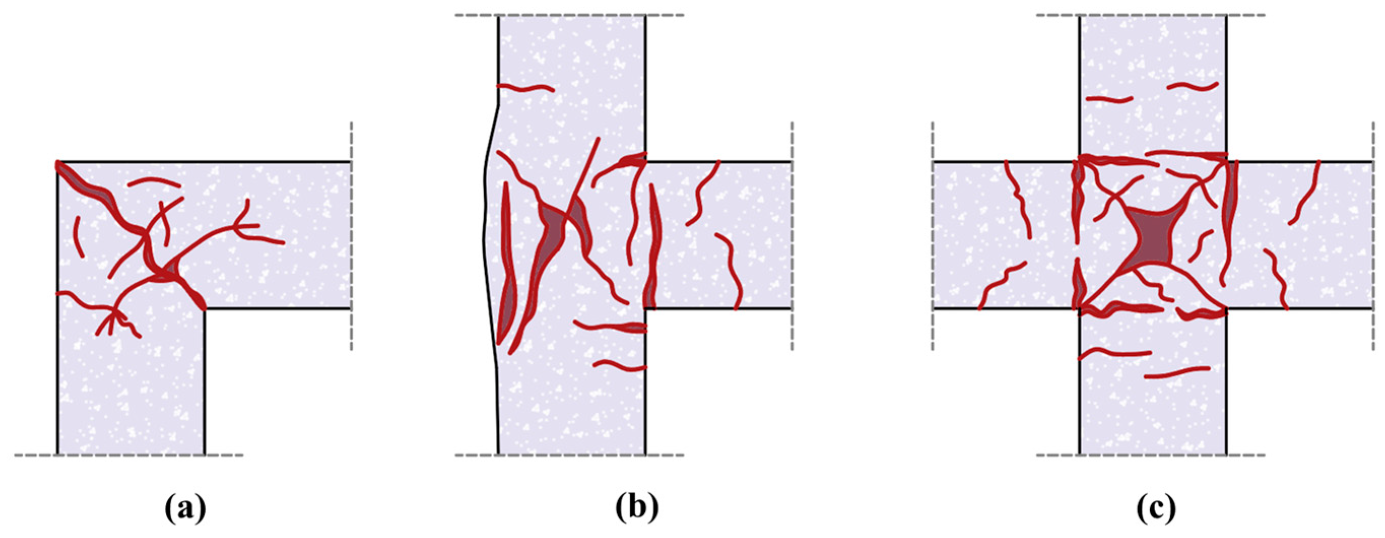
8]. This type of damage occurs in the most severe scenarios during an earthquake. It contributes to a reduction in the stiffness of the structural element to an unpredictable degree. As such, it is important to exercise special care for this part of the structural system even when microcracks are beginning to form. Damage from cyclic loading at beam–column joints is categorized into three types: corner joint failures, exterior joint failures, and interior joint failures, as illustrated in
Figure 1 [
9]. The primary goal of seismic design is to limit the development of potential plastic hinges at the column faces of a joint while permitting inelastic behavior to be distributed along the beam section. Such developments frequently lead to the spalling of cover concrete and anchorage failures due to the residual deformations at the joint.
To thoroughly examine and significantly improve the seismic performance of RC structures, numerous previous studies are explored within four interconnected and highly relevant methodological areas: analytical modeling techniques, experimental investigations conducted in controlled environments, the comparative analysis of various seismic design codes and guidelines, and studies supporting targeted retrofitting strategies. This comprehensive approach not only enhances understanding but also ensures the practical applicability of the findings in real-world scenarios.
Recent advancements in analytical modeling have substantially improved our ability to predict the seismic responses of reinforced concrete (RC) beam–column joints. Pantò [
10] introduced a novel macro-element for analytical modeling, specifically designed for joints with hinges, which proficiently represents the nonlinear characteristics associated with RC beam–column joints. The proposed model accounts for the nonlinear shear response of the central panel, the bond–slip behavior of longitudinal reinforcement bars, and the nonlinear dynamics occurring within plastic hinge zones. Hassan et al. [
11] proposed a model that exhibits a consistent probability of exceedance at 50%, which is in accordance with the revised provisions for nonlinear beams and columns. Furthermore, it reveals a strong correlation with both the test database and the validation datasets. This correlation indicates that revising existing seismic assessment standards in light of this model could improve both the precision and cost-effectiveness of performance-based seismic design for ductile concrete frames. Collectively, these validated analytical methodologies from the recent literature provide robust and precise tools for evaluating seismic vulnerabilities, facilitating targeted and effective retrofitting solutions to enhance structural resilience. Grande et al. [
12] underscore the essential function of beam–column joints in evaluating the seismic safety of RC frames. It particularly draws attention to the unforeseen damage mechanisms that have emerged during previous seismic occurrences, which significantly impacted these joints. To investigate this further, the authors formulated a finite element model introducing an additional element positioned between the beam and column members. This model effectively replicates the nonlinear behavior of beam–column joints, thereby illustrating the importance of incorporating these joints in the seismic analysis of RC frames through numerical simulations. Suwal and Guner [
13] discussed improvements in analytical modeling achieved by creating a feed-forward artificial neural network (FFNN) designed to estimate the shear strengths of beam–column joints made of RC. The proposed methodology improves the precision and dependability of forecasting seismic responses, effectively mitigating the shortcomings associated with conventional rigid-end offsets in joint modeling.
Complementing these analytical studies, experimental investigations remain indispensable for validating theoretical models and capturing complex seismic phenomena empirically. Fundamental experimental methodologies, such as shake table and cyclic load testing, enable researchers to simulate realistic earthquake scenarios, facilitating detailed analyses of structural responses within controlled laboratory settings. Studies consistently underscore the susceptibility of beam–column joints, highlighting prevalent damage patterns like severe shear cracking, concrete spalling, bar slip, and a loss of joint confinement. Hanson and Connor [
14] were pioneers in experimentally demonstrating that beam–column joints, which are confined to all four sides by beams, show enhanced performance under reversed cyclic loading. Their findings led to the conclusion that such joints do not need additional shear reinforcement. On the other hand, joints that lack confinement necessitate both shear and transverse reinforcements to mitigate damage from shear cracking and to prevent the buckling of the longitudinal column reinforcement. The seminal work by Hanson and Connor [
14] is recognized within the ACI 318-19 [
15] seismic provisions as foundational research significantly influencing modern seismic design codes. Their experimental findings demonstrated that RC beam–column joints confined by beams on all four sides exhibited substantially improved seismic performance under cyclic loading, even without additional shear reinforcement. This crucial observation has led to current seismic design standards to prioritize enhanced detailing requirements for joints lacking such beneficial confinement. Specifically, their work underpins the mandate for explicit shear and transverse reinforcement in joints not adequately confined by beams, highlighting a critical vulnerability previously underestimated in earlier design codes. Consequently, the contemporary seismic design codes extensively incorporate insights from Hanson and Connor [
14] by emphasizing rigorous beam–column joint detailing, proper confinement, and reinforcement practices. Subsequent experimental findings revealed that extensions of beams and columns, when adequately sized and reinforced with both longitudinal and transverse bars, effectively confine the joint faces. For instance, Ricci et al. [
7] conducted a series of rigorous experiments on unreinforced exterior beam–column joints using plain bars, revealing pronounced shear cracking, significant concrete spalling, and the severe degradation of stiffness under cyclic loading conditions. In parallel, Benavent-Climent et al. [
16] performed comprehensive shake table tests on RC waffle-flat plate structures. Their experiments highlighted critical phenomena such as substantial stiffness reduction and strength deterioration approaching 30% under seismic loading. The collapse process of RC frames has also been scrutinized in a scaled experimental setting. Li et al. [
17] conducted shake table tests on a three-story RC frame, systematically capturing the progressive deterioration and eventual collapse mechanism under severe seismic actions. Moreover, the work by Ahmad et al. [
5] on non-compliant special moment-resisting frames (SMRFs) further elucidates the impact of deficient seismic detailing on structural performance. Their shake table experiments demonstrated that RC frames not designed in accordance with modern seismic codes exhibit marked performance degradation, including reduced energy dissipation and increased susceptibility to brittle failure modes. Complementing these studies, Rizwan et al. [
18] compared the seismic performance of compliant and non-compliant special moment-resisting frames through extensive experimental campaigns. Their results highlight significant performance differentials, with non-compliant frames exhibiting lower ductility and greater strength losses during cyclic loading. In a broader context, Gautam et al. [
3] examined the seismic fragility of both the structural and non-structural components of RC buildings in developing countries, employing scaled experimental techniques to quantify vulnerability.
The comparative studies of international seismic design codes and standards represent the third key domain of research, highlighting the importance of analyzing and harmonizing variations in global seismic design practices. Parate and Kumar [
19] extensively reviewed shear strength criteria for beam–column joints across multiple international codes, identifying significant inconsistencies and recommending unified guidelines to enhance global seismic safety standards. Fardis [
20] underscores that the CEB/FIP (Seismic Model Code) [
21] and Eurocode 8 (2004) [
22] utilize varying models for assessing the shear strength of RC joints. In this study, a novel rational model was introduced to characterize the cyclic shear strength of RC joints. Pauletta et al. [
23] concluded that exterior RC beam–column joints lacking ties that are mandated by building codes within the joint core demonstrate considerable susceptibility to seismic forces. This vulnerability results in possible failure mechanisms that could undermine the structural integrity in the occurrence of seismic activities. Basu and Lakhani [
24] presented an implicit framework for the evaluation of joint shear strength in RC beam–column connections. This framework incorporates a range of factors, including strut width, compression depth, axial loading, and bending moments at both ends of the beam and column at the point of failure. The primary objective of this approach is to ensure compliance with seismic design criteria while offering a structured methodology for accurately estimating the shear strength of the joints. Tsonos [
25] introduced simplified evaluation methodologies for joint strengths across various international codes, advocating practical yet accurate assessment tools suited for real-world engineering applications. Such comparative analyses contribute significantly toward advancing and standardizing global seismic design provisions, ensuring robust structural safety and resilience across diverse regions. Chu et al. [
26] indicated that the shear capacity exhibited by steel-reinforced concrete (SRC) column–steel beam joints demonstrates an upward trend in correlation with an increase in the axial compression ratio. This suggests that the load-bearing potential of such joints can be significantly improved through the strategic optimization of the axial loads imposed on them.
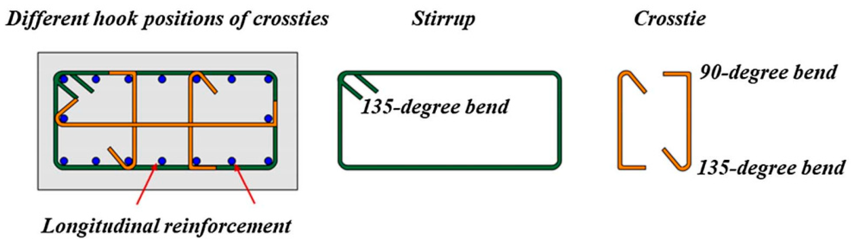
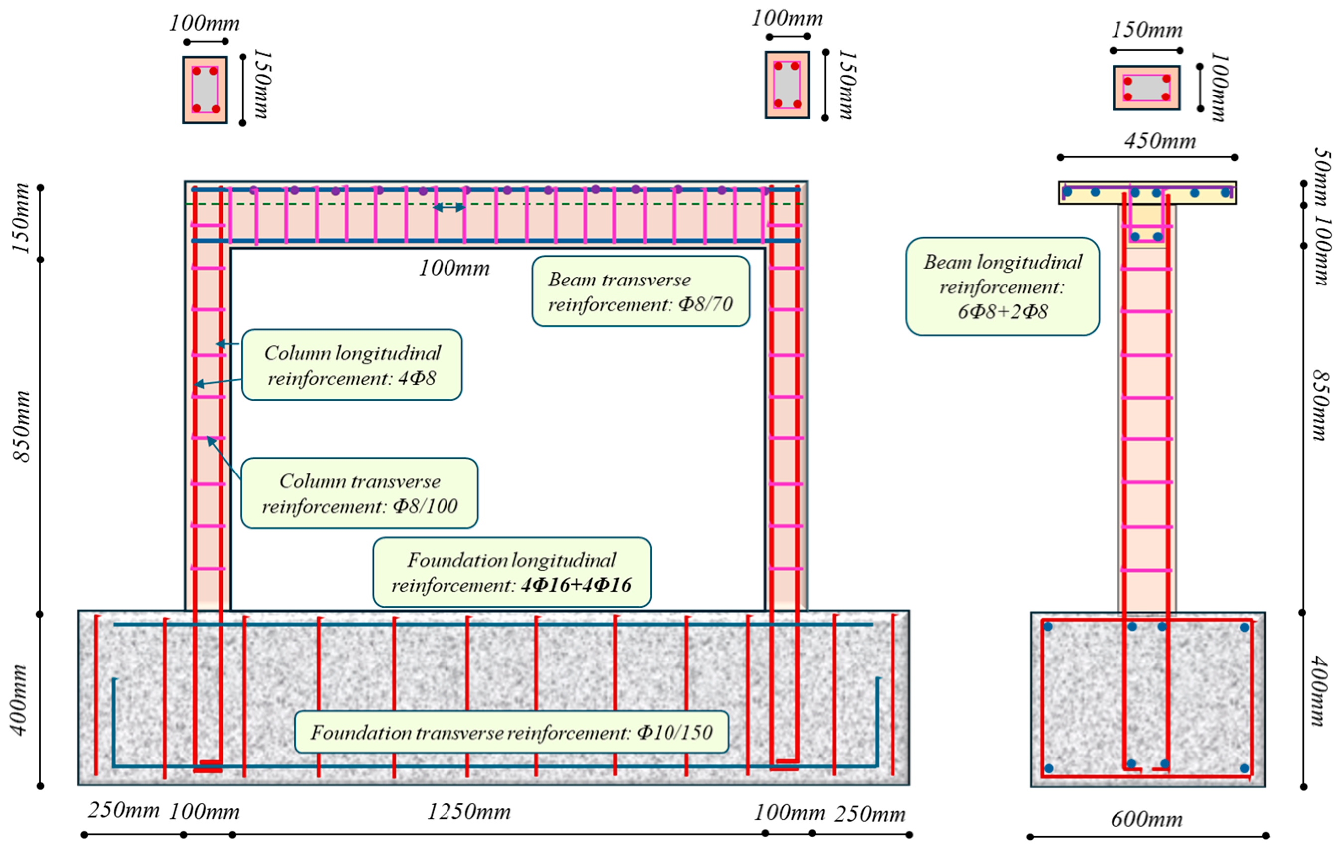
At present, the formulas employed for determining joint shear strength are based on findings from earlier experimental studies. According to the latest seismic code of Türkiye (TBEC 2018) [
27], a minimum of 40% and 60% of the transverse reinforcements must be placed in the confinement zone of the column, distributed along the heights of the confined and unconfined joints, respectively. The code outlines that confinement for concrete is achieved through the use of transverse reinforcements, which include stirrups, hoops, and crossties. To ensure proper anchorage, it is essential that stirrups, hoops, and crossties incorporate a seismic hook that bends at least 135°. Hoops are defined as closed ties that may consist of multiple reinforcing elements, each equipped with seismic hooks on both ends, and continuous wound ties possessing seismic hooks at both ends. Crossties, on the other hand, are continuous reinforcing bars featuring a seismic hook at one end and a hook bent at 90° at the opposite end; in this context, the hooks on the crossties should engage with the peripheral longitudinal reinforcing bars, as illustrated in
Figure 2 [
28].
Recent advances in retrofitting methodologies have demonstrated that targeted interventions can significantly improve the seismic performance of deficient RC structures. Experimental investigations have particularly highlighted the efficacy of advanced materials and techniques in addressing specific damage modes observed in beam–column joints. For instance, Vecchio et al. [
29] conducted an in-depth experimental study on RC beam–column joints retrofitted with fiber-reinforced polymer (FRP) systems. Their findings clearly indicate that the application of FRP wrapping not only enhances the shear capacity of the joint but also improves confinement, thereby mitigating the propagation of X-shaped shear cracks—a common damage pattern in inadequately detailed structures. Complementary studies by Realfonzo et al. [
30] further elucidate the cyclic behavior of RC joints strengthened with FRP, demonstrating significant improvements in energy dissipation and ductility. Additionally, Parvin and Granata [
31] have provided valuable insights into the effects of fiber composites on concrete joints, confirming that the application of such materials can substantially increase joint strength and delay failure mechanisms. These targeted retrofitting strategies, substantiated by empirical evidence and advanced analytical models, underscore the necessity of adopting a holistic approach to structural rehabilitation. Our work thus contributes to the evolving discourse on seismic retrofit interventions, providing a compelling framework for the application of scientifically validated retrofitting techniques in the modernization of aging RC infrastructure.
2. Objectives and Novelty of the Current Study
Despite notable progress across these four research trajectories, significant gaps remain, particularly the limited number of experimental studies that integrate realistic seismic data from recent earthquakes. Most existing experimental frameworks rely on artificially generated or historical seismic data, reducing the relevance and applicability of their findings to current real-world scenarios. Recognizing this critical limitation, the present research uniquely utilizes real seismic records from the catastrophic 2023 Kahramanmaraş earthquake in Türkiye within a shake table experimental framework. This innovative approach significantly enhances the practical applicability and empirical robustness of the research outcomes.
Many existing RC buildings unfortunately do not meet established quality standards. Historically, the performance of these inadequately designed frames during previous earthquakes has been concerning and unsatisfactory. Consequently, it is vital to conduct a comprehensive evaluation and improvement of these substandard buildings to mitigate potential risks and safeguard the safety of their occupants [
32].
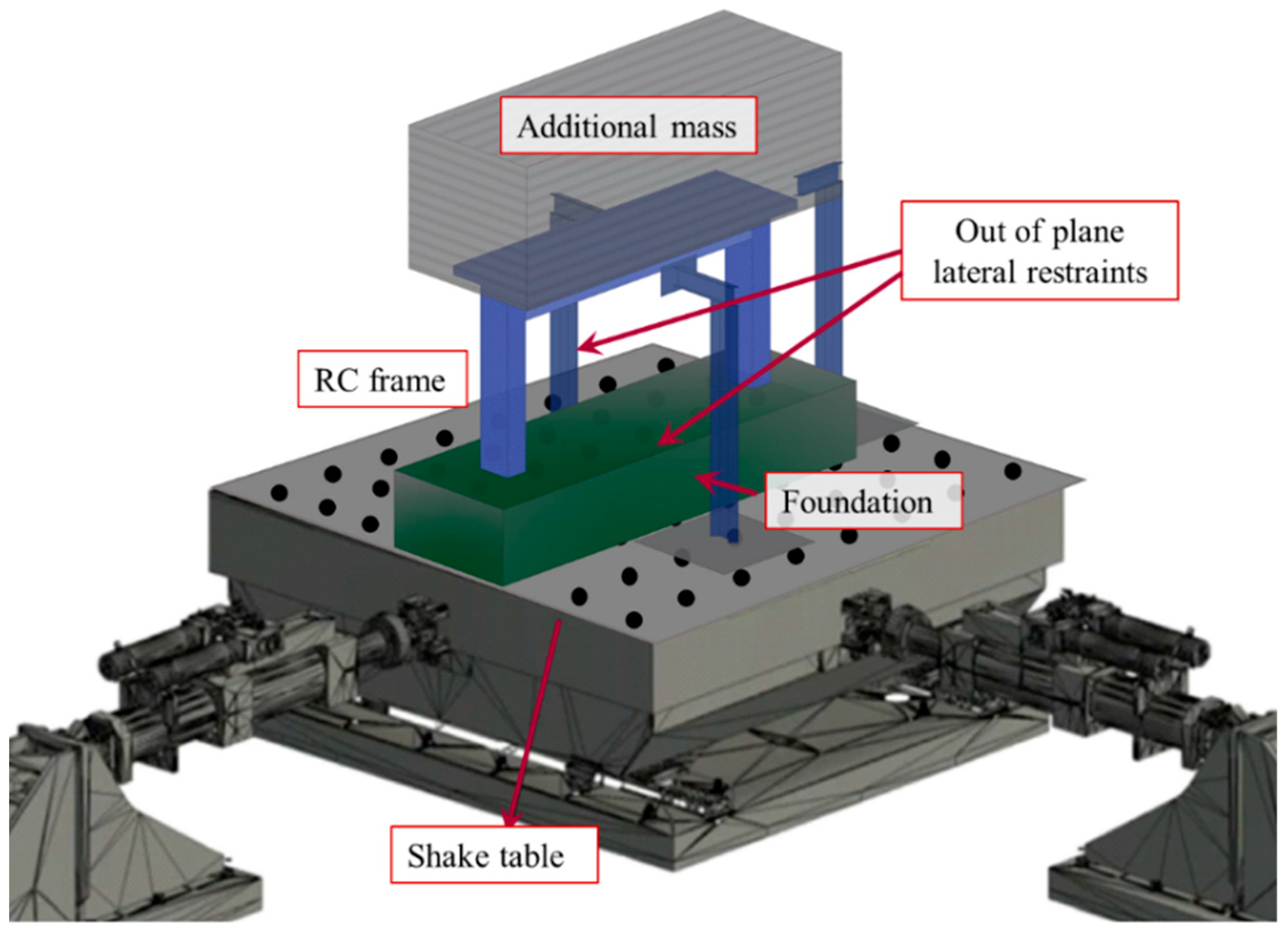
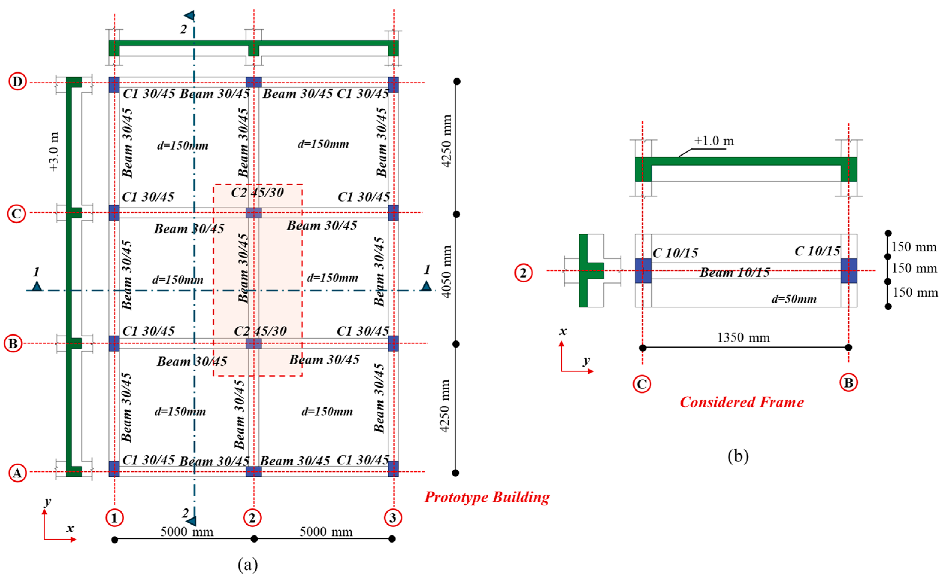
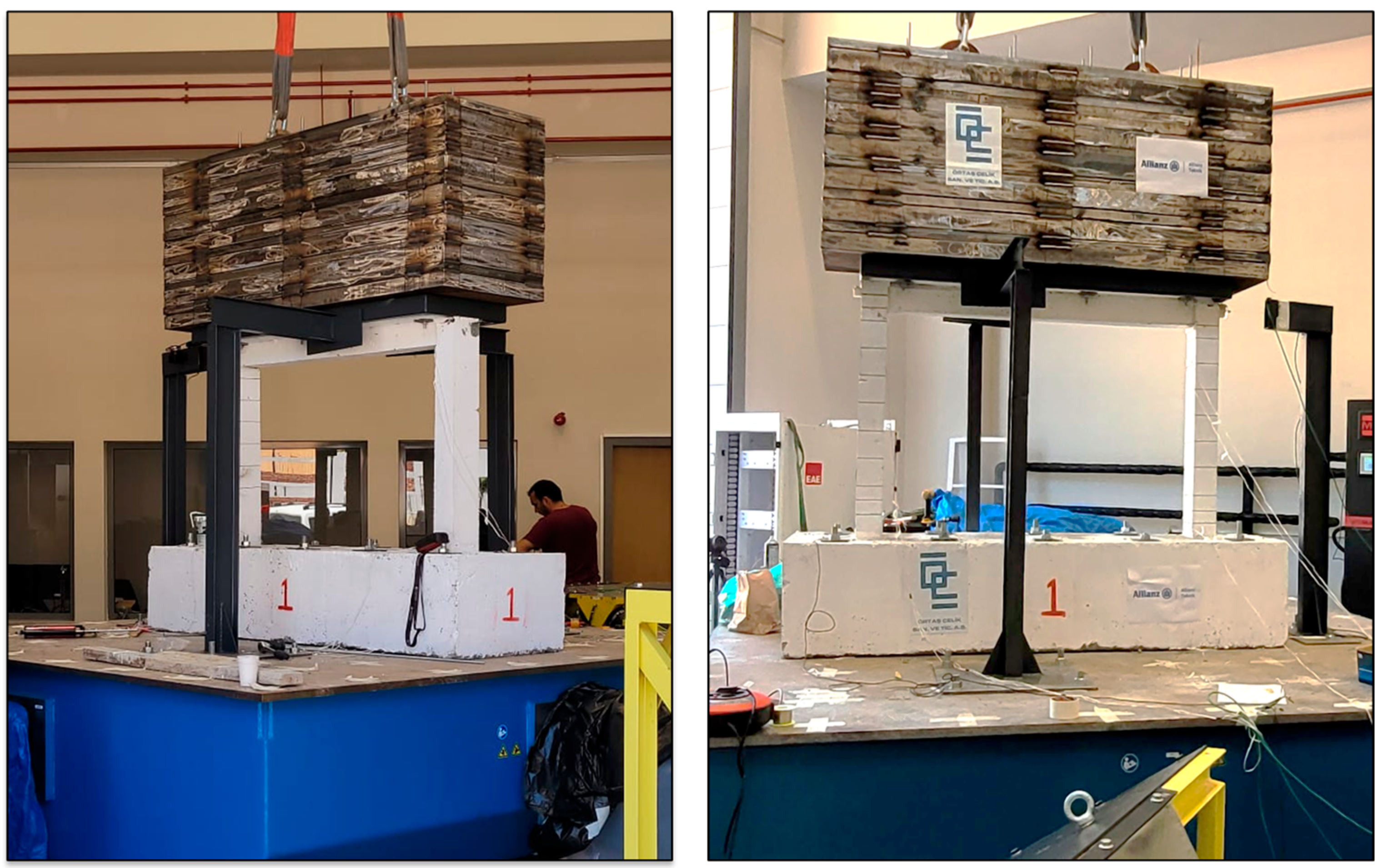
In pursuit of the stated ambitious objectives, the significant seismic event that occurred in Kahramanmaraş (Pazarcık) in 2023, characterized by a moment magnitude of 7.7, was employed as the basis for our research. Comprehensive shake table tests were conducted on a scaled specimen, representing one-third of the actual size, with a single story and bay configuration. The specimen was meticulously constructed to embody a typical substandard RC. The findings from this comprehensive investigation were meticulously evaluated and contrasted with respect to essential global response metrics, particularly the seismic code prerequisites. Additionally, the different damage patterns identified during the shake table tests were examined. This analysis seeks to offer a deeper understanding of the overall efficacy of the alternative design methodology.
The central objectives of this study are therefore to address these existing knowledge gaps by systematically quantifying the seismic responses of substandard RC beam–column joints under realistic earthquake loading conditions. The investigation specifically targets the shear strength, deformation mechanisms, and failure characteristics of joints prevalent in RC constructions. Additionally, this research critically evaluates the adequacy of contemporary seismic codes in addressing structural vulnerabilities identified experimentally. By employing meticulously scaled experimental models representative of common Turkish construction practices from the 1980s, the research not only contributes valuable insights into structural retrofitting techniques but also influences future policy developments and design regulations aimed at reducing seismic risks associated with older RC infrastructures.
4. Ground Motion Time History Applied in the Experimental Test
On 6 February 2023, at 04:17 local time (+3 GMT), a significant seismic event occurred in southeastern Türkiye, with a moment magnitude (
measured at 7.7. The Disaster and Emergency Management Presidency (AFAD) identified the epicenter of the earthquake in the Province of Kahramanmaraş, specifically near the town of Pazarcik [
42]. This incident is categorized as the 2023 Kahramanmaraş earthquake and transpired within a geological region designated as the Maraş triple junction, an area characterized by the intersection of the Arabian, Eurasian, and African tectonic plates. Comprehensive seismological data were gathered from 381 active monitoring stations, with station number 3141 selected for detailed experimental analysis. Notably, the maximum peak ground acceleration (PGA) recorded at this particular station reached 1.011 g in the north–south orientation.
Türkiye, geographically positioned on several major tectonic boundaries, frequently experiences significant seismic activities. Historical and recent seismic events have repeatedly highlighted vulnerabilities in building stock and urban infrastructure. Among the most devastating earthquakes to strike Türkiye are the 1939 Erzincan, 1999 Kocaeli, 2011 Van, and 2023 Kahramanmaraş earthquakes. The 1939 Erzincan earthquake (
), one of the most catastrophic historical earthquakes in Türkiye, occurred on 26 December 1939. It ruptured along the East Anatolian Fault (EAF), resulting in approximately 32.700 fatalities and extensive infrastructural destruction. This earthquake produced a rupture length of approximately 360 km with notable ground displacement observed in surface ruptures exceeding 7 m in certain areas [
43]. In contrast, the 1999 Kocaeli earthquake (
) struck the densely populated industrial Marmara region on 17 August 1999. Its epicenter was near Gölcük, with a rupture length of around 150 km along the western segment of the NAF, recording a PGA of approximately 0.51 g in Sakarya, severely impacting major urban areas such as İzmit and İstanbul, and resulting in over 17,000 fatalities and widespread building collapses [
44]. The 2011 Van earthquake, with a magnitude of
, occurred on 23 October 2011, in eastern Türkiye, along EAF, predominantly affecting rural and urban areas around the city of Van. The earthquake had a relatively shorter rupture length (approximately 60 km) but generated substantial damage in poorly constructed buildings, registering PGA values around 0.18 g in Van city center, with approximately 600 fatalities [
45].
The 2023 Kahramanmaraş earthquakes represent one of the deadliest seismic sequences in modern Turkish history. These events ruptured complex segments of the EAF and secondary faults, causing widespread devastation with a maximum PGA recorded as high as 2.22 g at stations near the epicentral region in Pazarcık. Over 50,000 fatalities and extensive infrastructural damage were reported, marking it as a catastrophic event [
42].
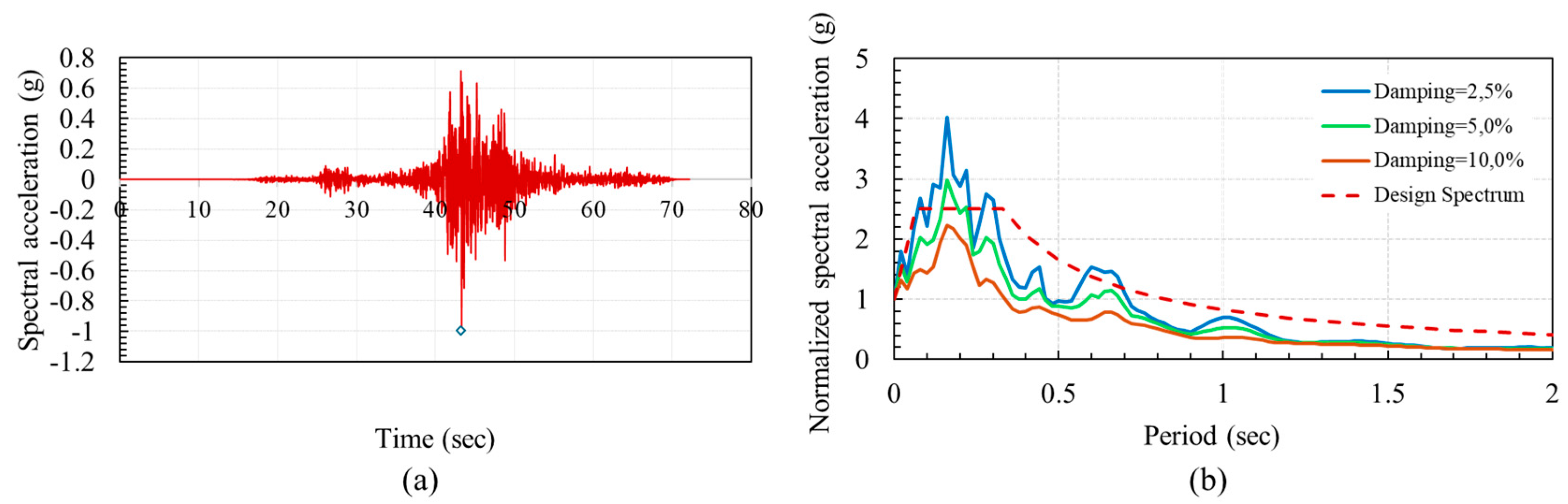
In this sequence, the frequency content was notably broadband, spanning short periods (below 0.5 s) to intermediate and longer periods (up to 2.0 s). This wide spectral distribution is attributed to the complex rupture process involving multiple fault segments. Additionally,
Table 6 presents a comparison of significant earthquakes that occurred on the EAF.
The latest iteration of the Turkish Building Earthquake Code [
27] delineates the seismic risk into four distinct categories: DD-1, DD-2, DD-3, and DD-4. These classifications reflect the probability of seismic events occurring, with exceedance probabilities of 2%, 10%, 50%, and 68%, respectively, over a 50-year horizon. The calculated average recurrence intervals for seismic events within these categories are approximately 2475 years for DD-1, 475 years for DD-2, 72 years for DD-3, and 43 years for DD-4. Additionally, each seismic level is aligned with specific earthquake scenarios, which include the maximum considered earthquake (MCE) assigned to DD-1, the design-based earthquake (DBE) for DD-2, the frequent earthquake (FE) relevant to DD-3, and the service-level earthquake (SE) for DD-4. In this context,
Figure 8 illustrates the normalized response spectra associated with the DD-2 category, juxtaposed with a scaled time-history of the 2023 Maraş earthquake, incorporating critical damping values of 2.5%, 5%, and 10%. The analysis of this figure indicates that the chosen acceleration time history is appropriate for conducting experimental tests on the specified test frames.
Initially, the frame underwent testing under ground motion that was carefully scaled in accordance with the previously discussed similitude law. Given that the frame was engineered to be substandard, the application of the scaled ground motion was carried out meticulously.
5. Results
Accordingly, the initial frequency of the specimen was identified as
Hz.
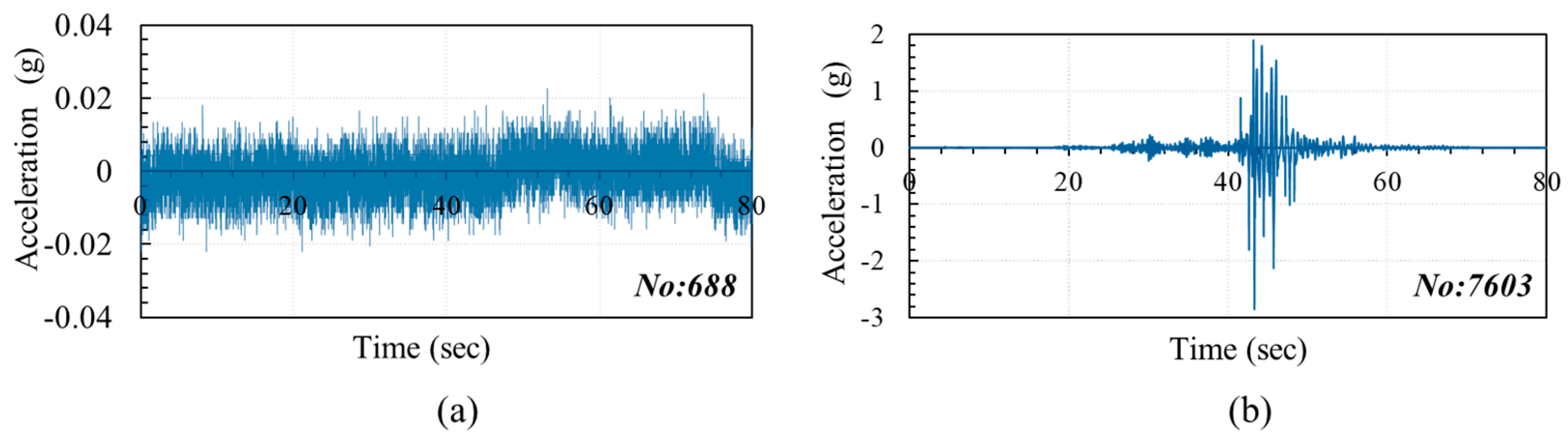
Figure 9 presents the acceleration measurements obtained from Stations 688 and 7603 for the specified specimen. The data presented in the figure suggest that station 688 experienced a malfunction during the testing process. Consequently, the sole source of acceleration data are derived from station 7603.
The maximum lateral displacements observed at the top of the specimen, as measured by LVDT#1, are presented in
Figure 10. The peak lateral displacement recorded was approximately 53.1 mm, corresponding to a story drift ratio of approximately 0.055 radians when subjected to a ground acceleration of 0.35 g.
Chord rotation serves as a critical metric in assessing the structural performance and deformation capacity of reinforced concrete (RC) elements subjected to bending stresses. Its significance lies in the evaluation of essential characteristics such as ductility, damage state, and the failure mechanisms of RC components, including beams, columns, and walls, particularly when they are exposed to seismic forces. Low-strength concrete exhibits a chord rotation capacity that is approximately 30–50% greater than that of normal-strength concrete. This enhanced capacity can be attributed to its superior ability to deform under stress. Following the completion of the tests, the calculated chord rotation value for the specimen was determined to be 0.038 radians. This measurement is noted to surpass the specified chord rotation threshold established in ASCE 41-23 [
47].
A hysteretic curve illustrates the cyclic response of a structural component, such as a reinforced concrete beam or column, subjected to recurrent loading and unloading, notably in the context of seismic activity. This curve delineates the correlation between lateral force and displacement through successive loading cycles. In the case of low-strength concrete, the hysteretic curve generally reveals certain characteristics: pinching effects that arise from bond slip and cracking, a decline in strength and stiffness across loading cycles, and diminished energy dissipation when compared to elements that are well confined.
Hysteresis models, which are extensively employed in the analysis of low-strength concrete structures, exhibit several significant limitations that warrant detailed examination. The constraints inherent in these hysteretic models primarily stem from the foundational assumptions incorporated within them. Typically, a multitude of models can be proposed for identical structural elements and loading scenarios, often resulting in contradictory outputs. For example, various models and their derivatives present disparate approaches to modeling the same phenomena. Moreover, even when the same modeling technique utilizes identical operators, such as R, it can yield divergent mathematical formulations.
Numerous empirical hysteretic models have been introduced to capture the force-displacement characteristics of structural elements, with the Mainstone model being one of the earliest examples. Subsequent models tend to provide an algebraic representation of the force–displacement relationship, delineating elastic and plastic branches. Contemporary structural codes for low-strength concrete predominantly endorse such models within displacement-based design frameworks. However, a notable inconsistency emerges between the experimentally derived and analytically predicted ratios of hysteresis loops for low-strength concrete walls. In addition, the overall load-carrying capacity of low-strength concrete buildings is highly sensitive to the capacity for plastic hinge displacement. This sensitivity highlights the crucial role that low-strength concrete structures play in the seismic resilience of developing economies [
48].
In light of these factors, the aforementioned limitations pose serious implications for the safety and design integrity of low-strength reinforced concrete structures. To address these issues, the Venantius model has been proposed to characterize the pinching force–deformation relationship in reinforced concrete members, specifically for two-dimensional low-strength concrete structures. The axial load ratio emerges as the predominant factor since it directly influences inelastic curvature constraints. Furthermore, analysis of concrete-confined braces demonstrates the critical impact of the axial load ratio, particularly when reductions in concrete confinement are applied. The findings presented underline the necessity for more sophisticated modeling approaches to accurately assess hysteretic deformation demands in the design of low-strength concrete structures, particularly in the context of performance-based design methodologies [
49].
Figure 11 presents a graphical representation of the relationship between base shear and displacement for the specimen in question.
The degraded material response of concrete and reinforcements is investigated over time with the aim of simulating and monitoring the damage in the lacking elements of the structure. The stiffness and strength degradation of a reinforced concrete structure may develop due to a range of factors or the combined effect of these factors. The cracking of concrete is a gradual process, but the growth of crack width is not constant. If a crack becomes interconnected, the development of a crack-widened region rapidly increases material deterioration. Moreover, a wider crack may accelerate the degradation in stiffness or strength. It is important to understand how material deterioration progresses in relation to the change in structural conditions. Depending on the material properties of concrete and rebar or the geometrical conditions of a cross-section, various types of cracks can be considered. However, the growth of crack width is closely related to a change in structural conditions. This occurrence is referred to as pinching. The behavior associated with pinching is identified by significant decreases in stiffness upon reloading following an unloading phase. Additionally, there is a noteworthy recovery of stiffness when a displacement is applied in the reverse direction. In
Figure 11, there is a clear indication of the reductions in both stiffness and strength, alongside the presence of a pinching effect.
When a ground motion level of 0.35 g was applied to the specimen, observable damage was evident at the beam–column connections. Furthermore, there was noticeable concrete spalling present in these sections, as depicted in
Figure 12 and
Figure 13. During the testing process, small fissures emerge at the connection between the beam and column as a result of alternating moments. This phenomenon is subsequently accompanied by the deterioration of the concrete cover. It can be inferred that the insufficient anchoring of the longitudinal reinforcement permits a slippage of the bars within the joint, thereby contributing to a decline in structural strength. Additionally, a lack of transverse reinforcement has resulted in the formation of diagonal shear cracks that exhibit an X-pattern. The computed Park–Ang damage index indicates that, in addition to the aforementioned deterioration, there is also evidence of reinforcement buckling.
6. Discussion
To assess the damage inflicted by an earthquake, it is essential to delineate the correlation between the intensity of ground motions and the resultant degree of damage to various structures. This correlation is commonly referred to in the technical literature as a damage function. To analyze the vulnerability of structures, various criteria have been developed to quantify damage [
50]. These criteria provide a framework for assessing the extent of structural damage based on established theoretical principles, ultimately resulting in the calculation of a specific metric known as the damage index. A significant damage index is introduced by Park and Ang [
37]. This index is characterized as a linear amalgamation of damage attributed to energy dissipation and the peak deformation experienced. Park and Ang [
37] substantiated their proposed equation through empirical test results collected from various researchers examining concrete columns and beams. In this approach [
37], the damage index (D) is defined as a combination of maximum deformation and cumulative energy dissipation, typically expressed as follows.
Here, in the equation,
and
refer to the maximum experienced displacement and ultimate displacement capacity, respectively.
is the total hysteretic energy dissipated (area enclosed by the hysteresis loops), and
is the yield base shear strength value. Further,
is a constant defined in [
37]. The assessed damage index stands at 0.89, categorizing it at the threshold of near collapse, yet still within the significant damage spectrum.
The present experimental investigation elucidates critical seismic performance characteristics of substandard RC beam–column joints, explicitly highlighting pronounced stiffness degradation, strength deterioration, hysteresis loop pinching, and extensive shear cracking under seismic loading conditions. Specifically, the tested structural model demonstrated explicit numerical values that clearly articulate and quantify structural vulnerabilities, directly underscoring critical deficiencies typical of older, inadequately reinforced RC constructions.
A comprehensive evaluation of recently published experimental studies involving similarly scaled tests corroborates our observations. Zhang and Li [
51], through the detailed cyclic load testing of RC beam–column joints, reported notable strength losses exceeding 30%, stiffness degradation, and pronounced shear cracking—findings directly aligned with our experimental outcomes. Likewise, Ricci et al. [
7] conducted cyclic loading tests on exterior RC beam–column joints, documenting significant shear cracking, concrete spalling, and severe joint deterioration. Their reported drift ratios and cyclic degradation trends remarkably parallel our observed data, emphasizing shared vulnerabilities and validating the reliability of our experimental approach.
Detailed comparative analyses with prior shake table studies further reinforce the robustness and accuracy of our findings. Benavent-Climent et al. [
16], in experiments on RC waffle-flat plate structures, documented substantial stiffness degradation of approximately 40%, and strength deterioration close to 30% under seismic actions—metrics closely corresponding to those observed in our current investigation. Similarly, Li et al. [
17] investigated a three-story RC frame subjected to shake table tests, highlighting comparable cyclic hysteresis pinching and progressive stiffness reductions. Notably, the drift ratios recorded in their study, approaching values of around 0.055 radians, show significant quantitative similarities to our experimental data.
7. Conclusions and Recommendations
Shake table testing of substandard RC frames has illuminated substantial structural deficiencies when subjected to seismic forces. The analysis reveals that issues such as inadequate reinforcement detailing, low concrete strength, inadequate confinement, and compromised beam–column connections result in considerable lateral deformations, early cracking, and, in certain instances, structural failure.
The shaking table experiment was conducted on a one-story specimen scaled to one-third of its original size, designed to represent substandard traditional RC frames prevalent in Türkiye. Upon completing the 0.35 g ground motion event, the substandard RC frame revealed substantial damage. Specifically, shear cracks were observed at the beam–column junctions of the initial specimen.
The experimentally obtained displacement thresholds, joint damage patterns, and damage indices from this study offer several direct contributions to current and prospective seismic design and retrofit provisions for older, low-strength RC frames:
- (i)
Refined Drift Capacities and Collapse Thresholds: the observation that major diagonal shear cracking and joint deterioration occurred around a story drift of approximately 0.055 radians highlights a realistic collapse prevention benchmark. Code drafters could integrate this evidence-based drift capacity into guidelines or commentary, ensuring that older frames receive adequate reinforcement or retrofitting before reaching critical drift levels under seismic demand.
- (ii)
Emphasis on Joint Confinement Requirements: the progression of X-shaped cracks in beam–column joints lacking adequate confinement underscores the urgent need for enhanced joint detailing measures, such as closely spaced stirrups, hoops with seismic hooks, and properly anchored crossties.
- (iii)
Shear-Critical Failure Indicators: the near-collapse Park–Ang damage index (0.758) directly correlates with shear-dominant failure in unreinforced or substandard joints. Integrating these damage index insights into code-based assessment frameworks promotes more stringent shear checks for beam–column connections, particularly in legacy structures erected under pre-seismic regulations.
Through these targeted refinements, the findings from this experimental campaign both strengthen and extend the body of knowledge underpinning contemporary seismic design codes. They provide tangible benchmarks for recognizing, quantifying, and mitigating collapse-prone failure mechanisms in substandard RC frames. Ultimately, the findings from this comprehensive study hold significant potential implications, providing essential knowledge and practical recommendations that can substantially enhance seismic safety, inform engineering practices, and guide policymaking within earthquake-prone regions.
The observed damage patterns necessitate urgent seismic retrofitting initiatives explicitly aimed at augmenting the resilience of these RC frames. Specifically, for the prominent X-shaped shear cracks identified in beam–column joints, the targeted application of FRP wrapping is recommended, as it significantly enhances the shear capacity and confinement, thereby mitigating brittle shear failures. Additionally, steel jacketing can be effectively employed for severely damaged columns to enhance their axial and shear capacities. Incorporating innovative braces such as BRBs can further improve overall lateral load resistance and ductility. Moreover, fortifying columns through strategic jacketing and the integration of contemporary seismic design methodologies, including capacity design principles, the proper anchorage of reinforcement, and meticulous detailing, can substantially elevate the structural integrity and seismic performance of RC frames in earthquake-prone areas.
In summary, the shake table experiments serve to underscore the susceptibility of substandard RC frames to seismic loading and highlight the critical need for preemptive retrofitting and compliance with seismic design standards to reduce potential hazards and improve structural safety. The retrofitting of existing deficient buildings and the implementation of rigorous seismic design regulations for new developments are essential strategies to reduce the risks associated with earthquakes. The results act as a compelling indication that anticipatory actions such as structural evaluation, rehabilitation, and adherence to current engineering guidelines are vital for improving the seismic robustness of RC structures, thereby protecting both lives and property.
While this study provides valuable empirical data derived from shake table testing, a notable limitation is the absence of complementary numerical modeling. To address this limitation, future research will involve detailed finite element analyses aimed at further validating and refining our understanding of the seismic behavior of RC beam–column joints, thus enhancing practical applicability and code relevance. The limitations of the test setup impacted the capacity, which required the specimens to be tested at a reduced scale. To ensure that the findings of this study can be effectively generalized, it is advisable to conduct tests on larger-scale frame specimens, as well as three-dimensional models, subjected to diverse earthquake ground motions in order to address various uncertainties inherent in the results.


