
Study on Cavitation Effects in Elastic Cylinder Displacement and Bubble Morphology: Modeling, Reliability, and Behavioral Analysis

Abstract
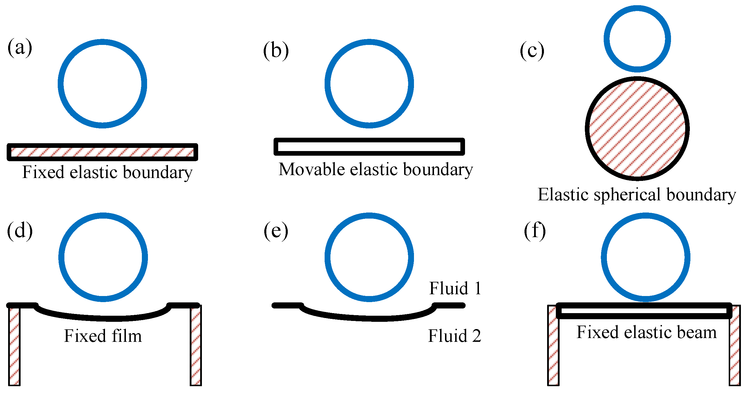
1. Introduction
2. Materials and Methods
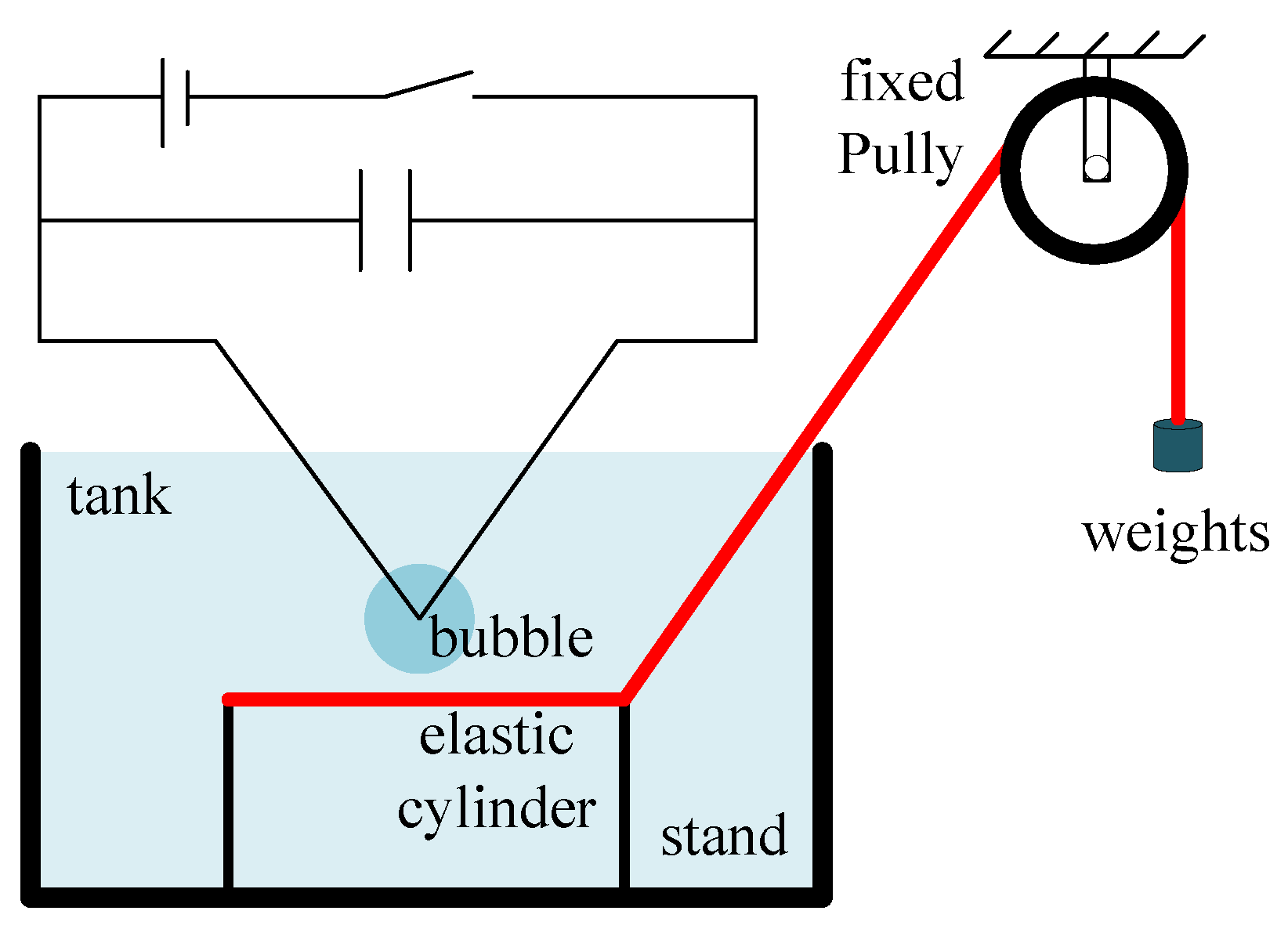
2.1. Experimental Setup
2.2. Dimensionless Parameters
3. Results and Discussion
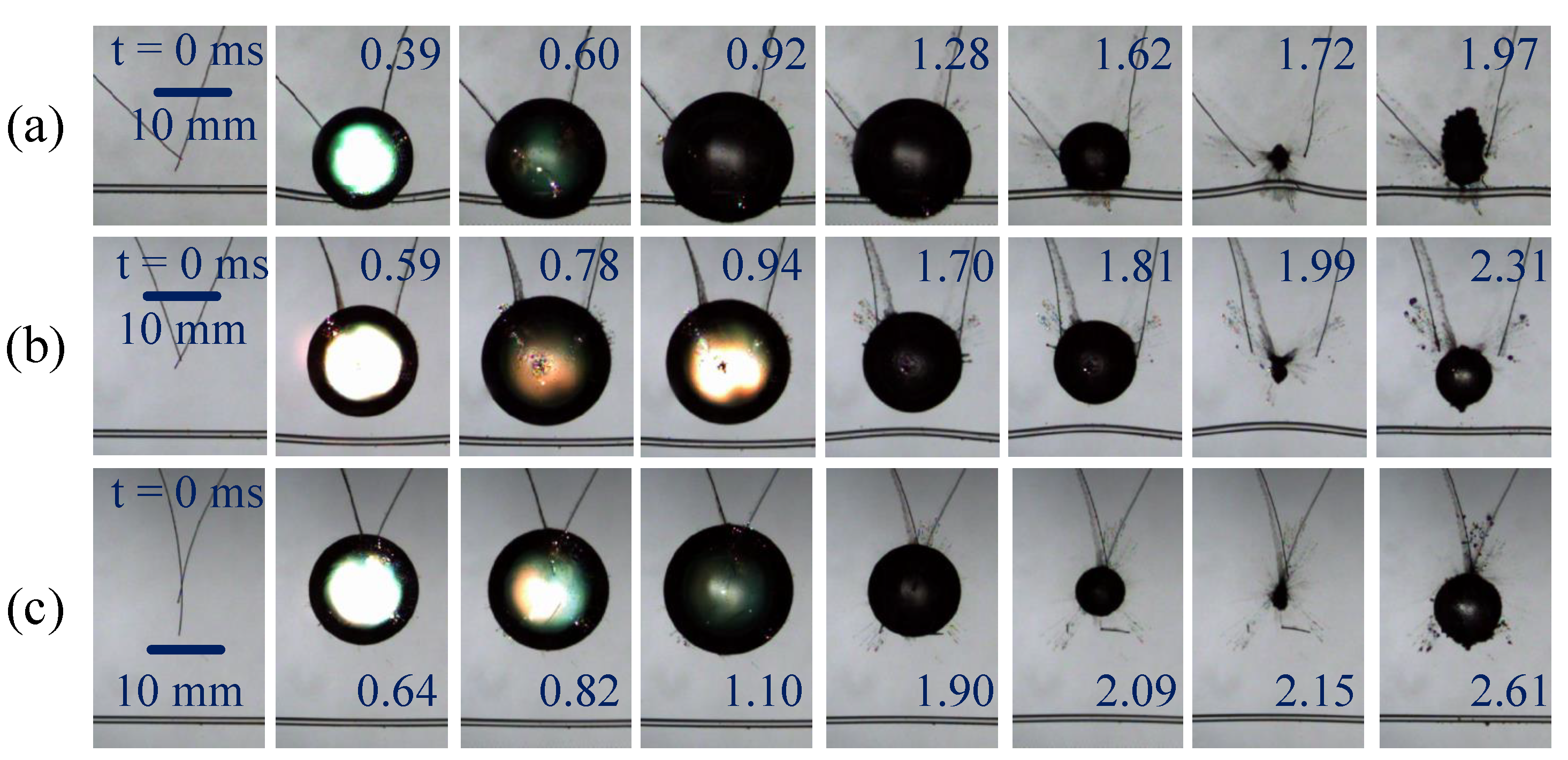
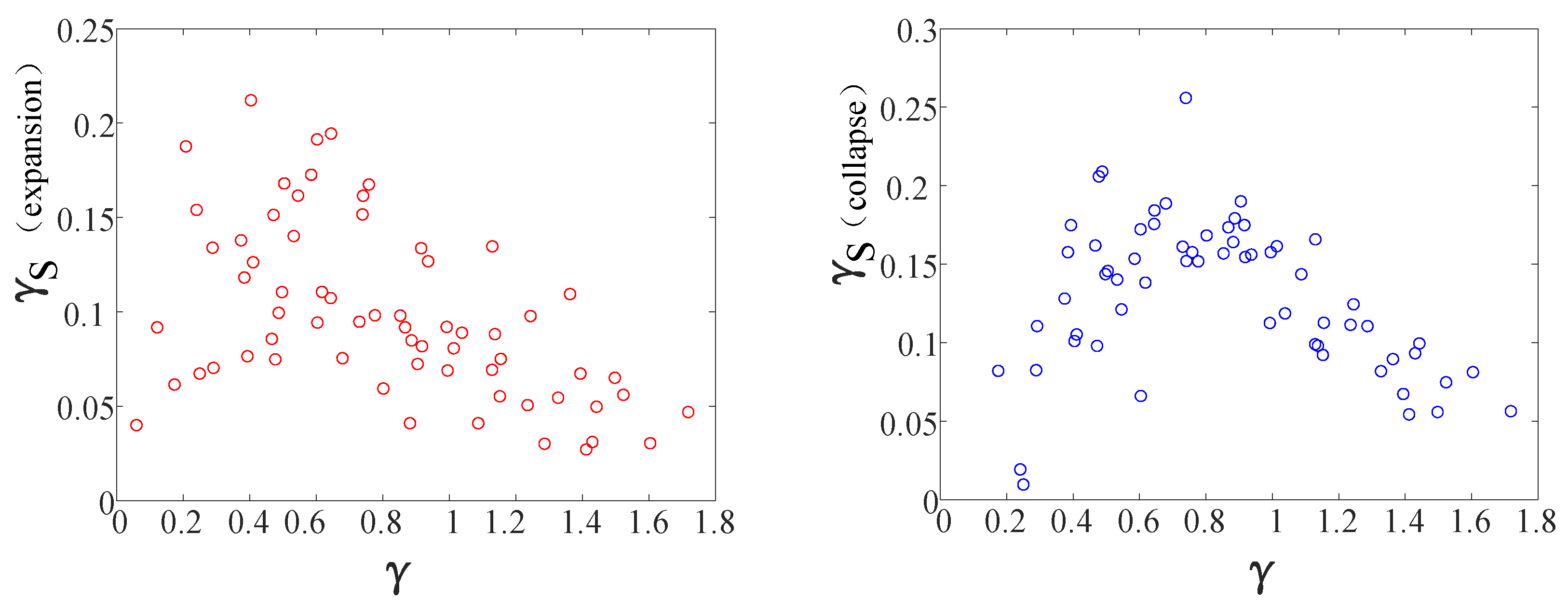
3.1. Bubble Motion
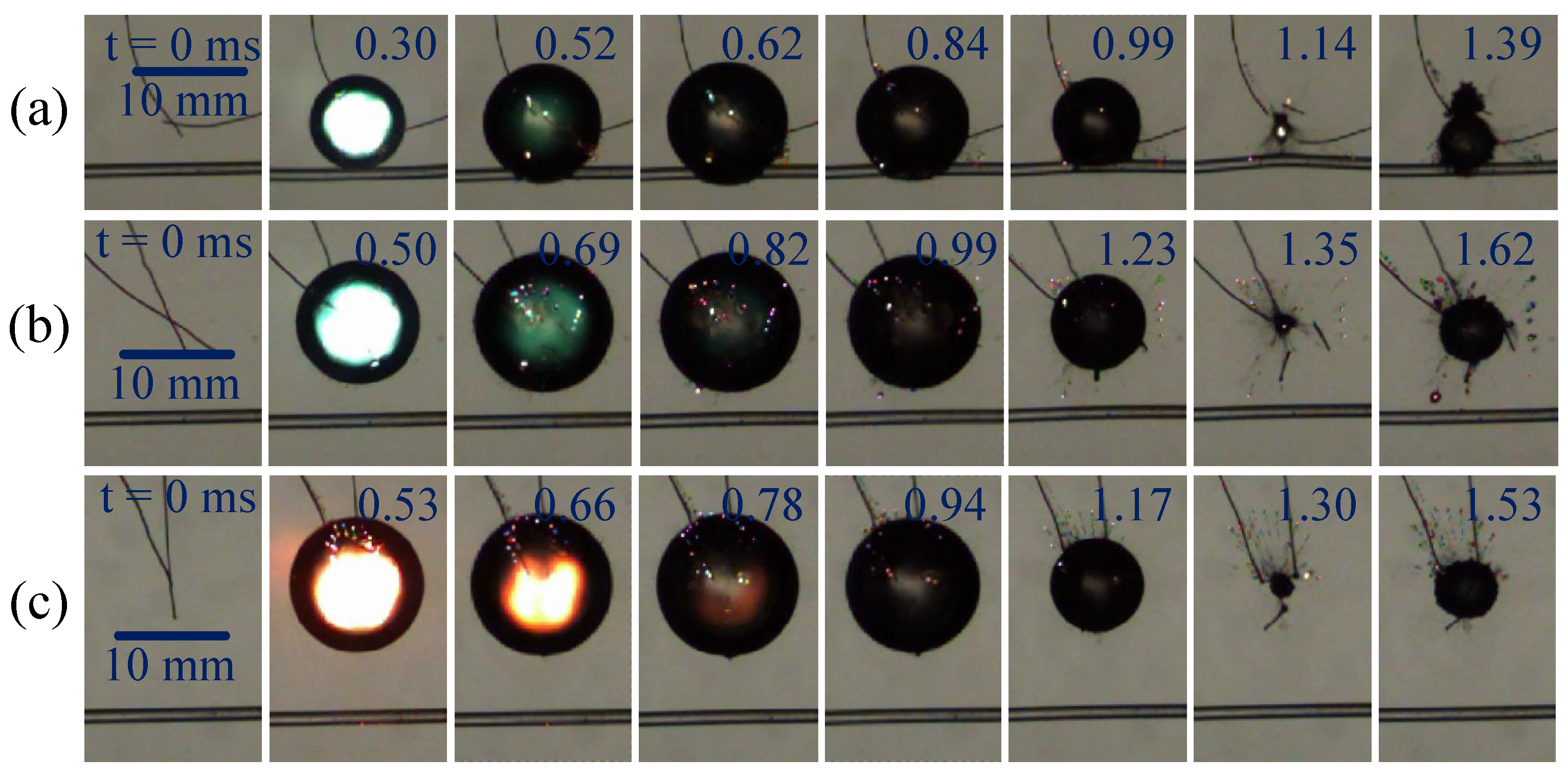
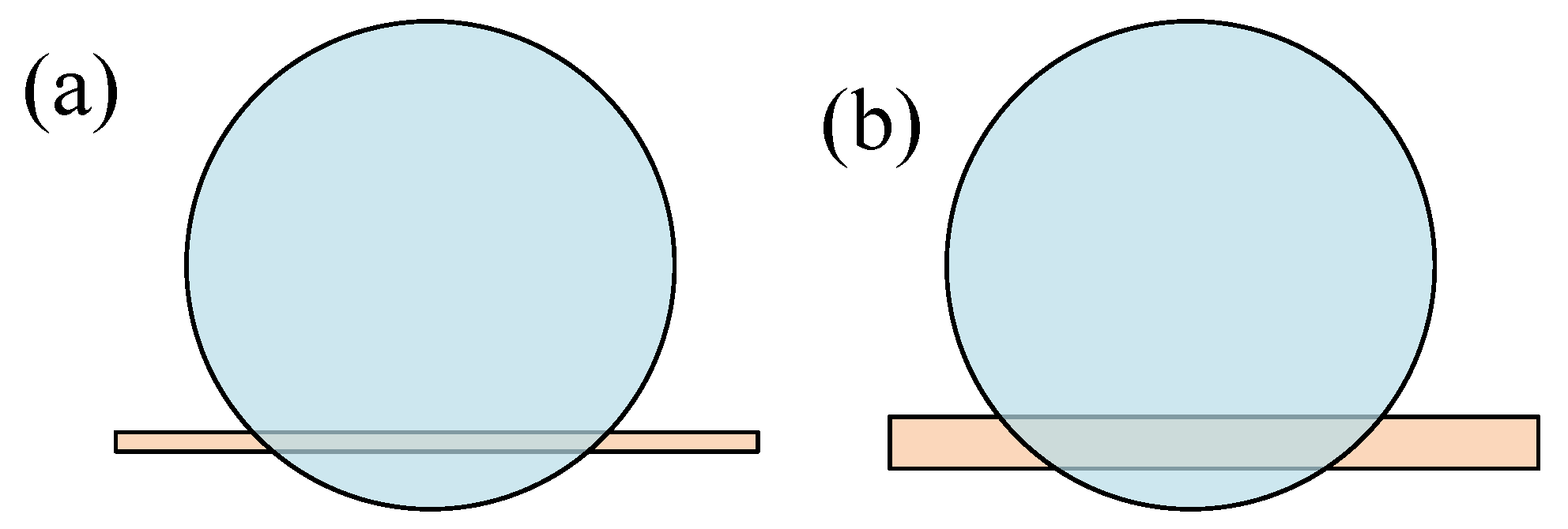
3.1.1. Bubble Motion near an Elastic Cylinder with Different Distances
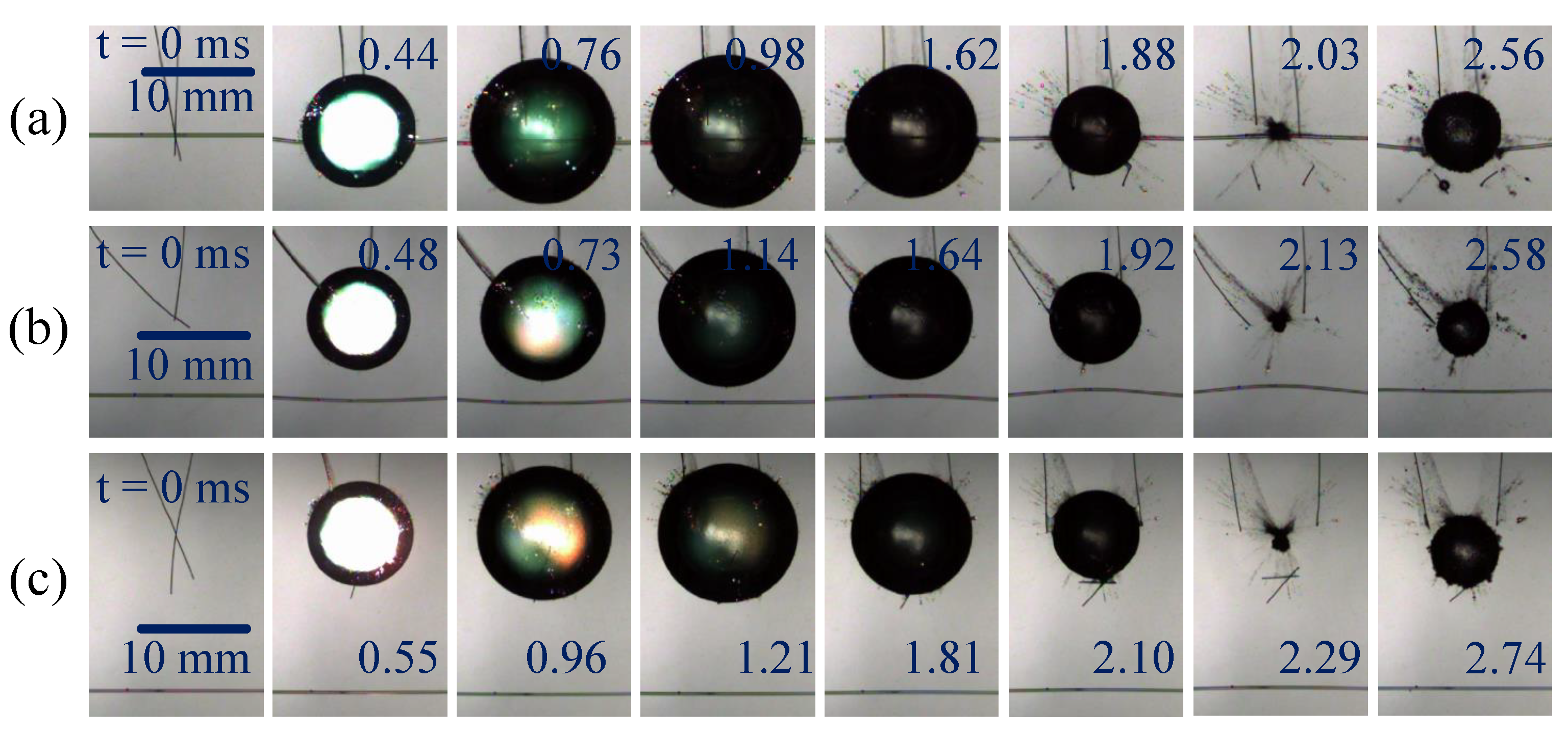
3.1.2. Bubble Motion near an Elastic Cylinder with Different Tension Values
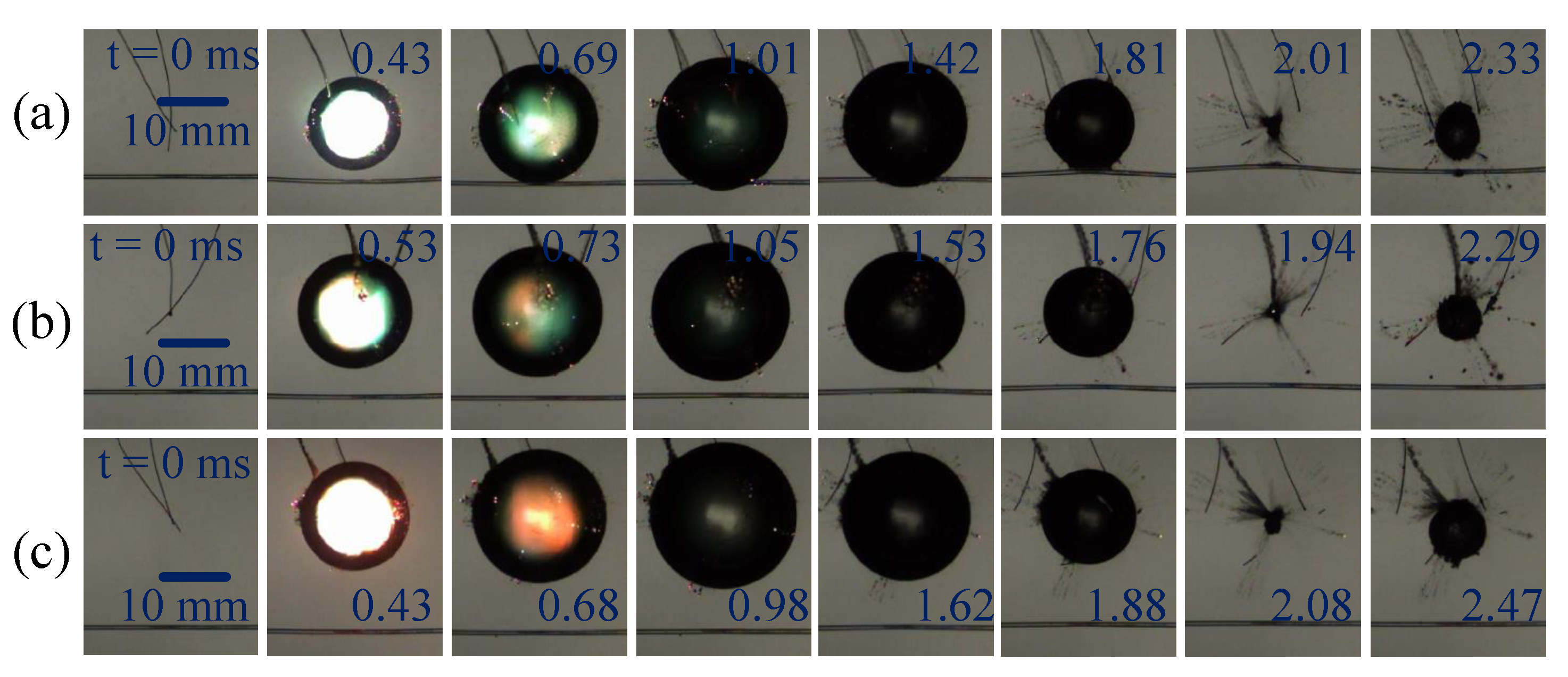
3.1.3. Bubble Motion near an Elastic Cylinder with Different Rod Sizes
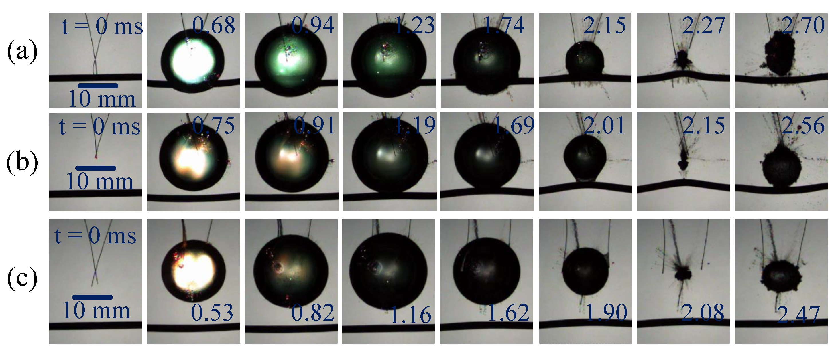
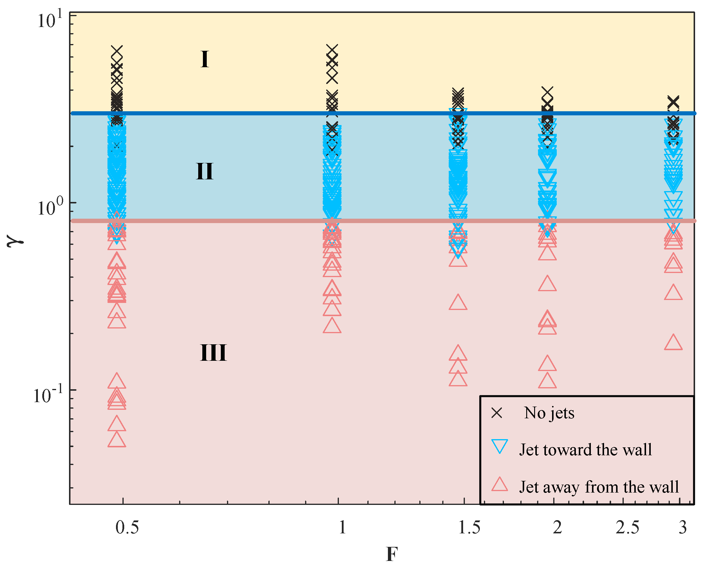
3.2. Effect of Jet Direction
3.2.1. Effect of Elastic Cylinder Tension on Jet Direction
3.2.2. Effect of Elastic Cylinder Size on Bubble Jet Direction
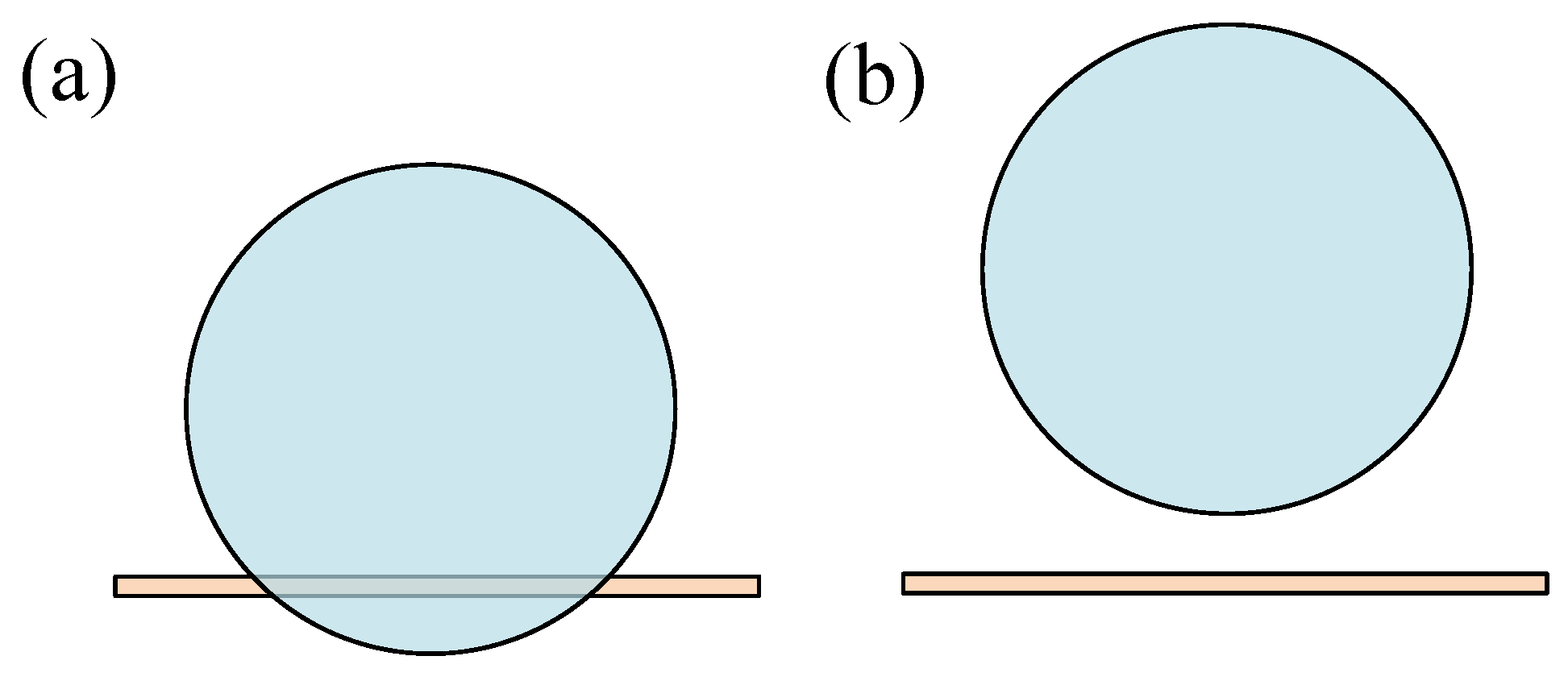
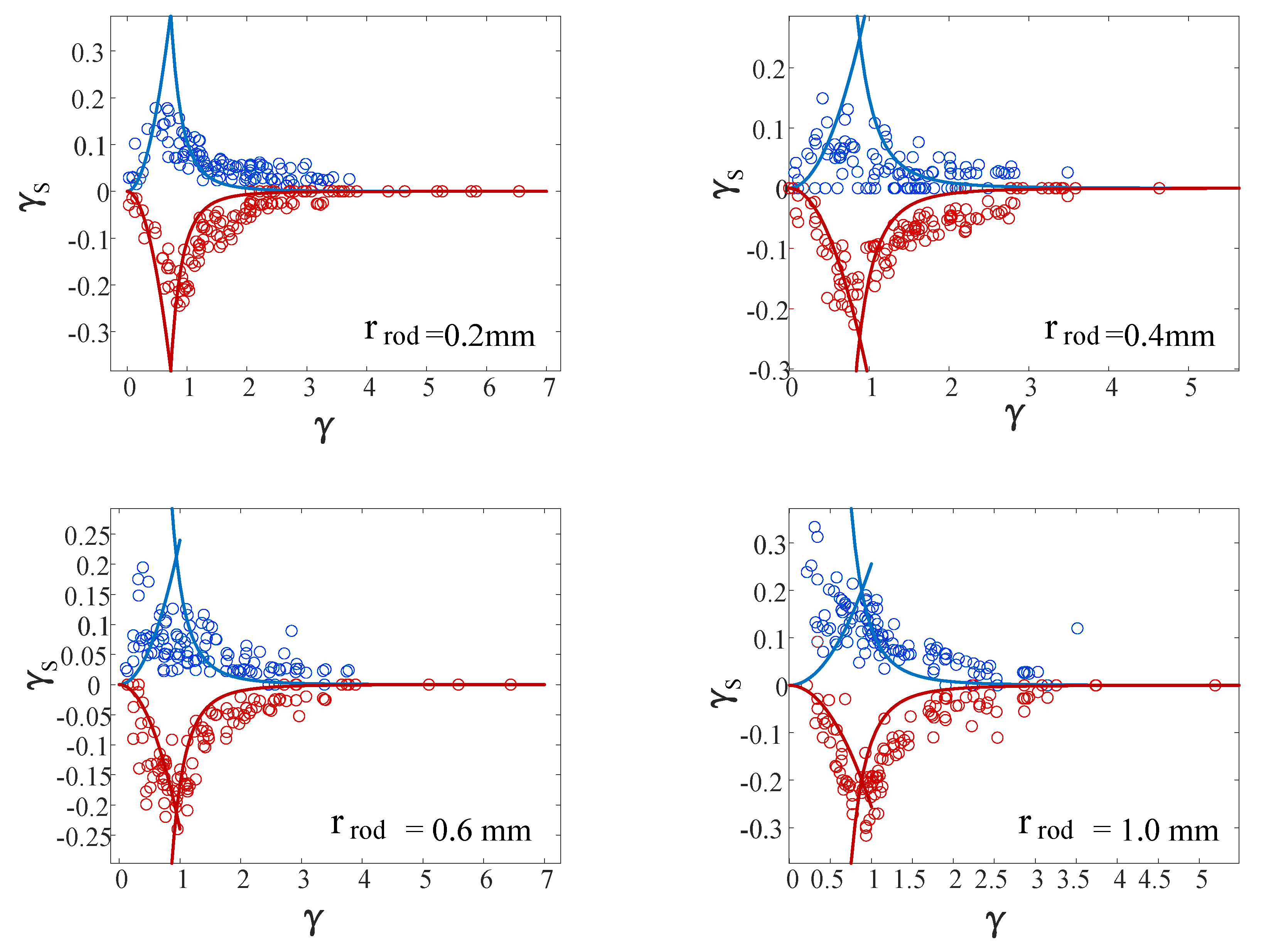
3.3. Effect of Bubbles on Displacement of Elastic Cylinder
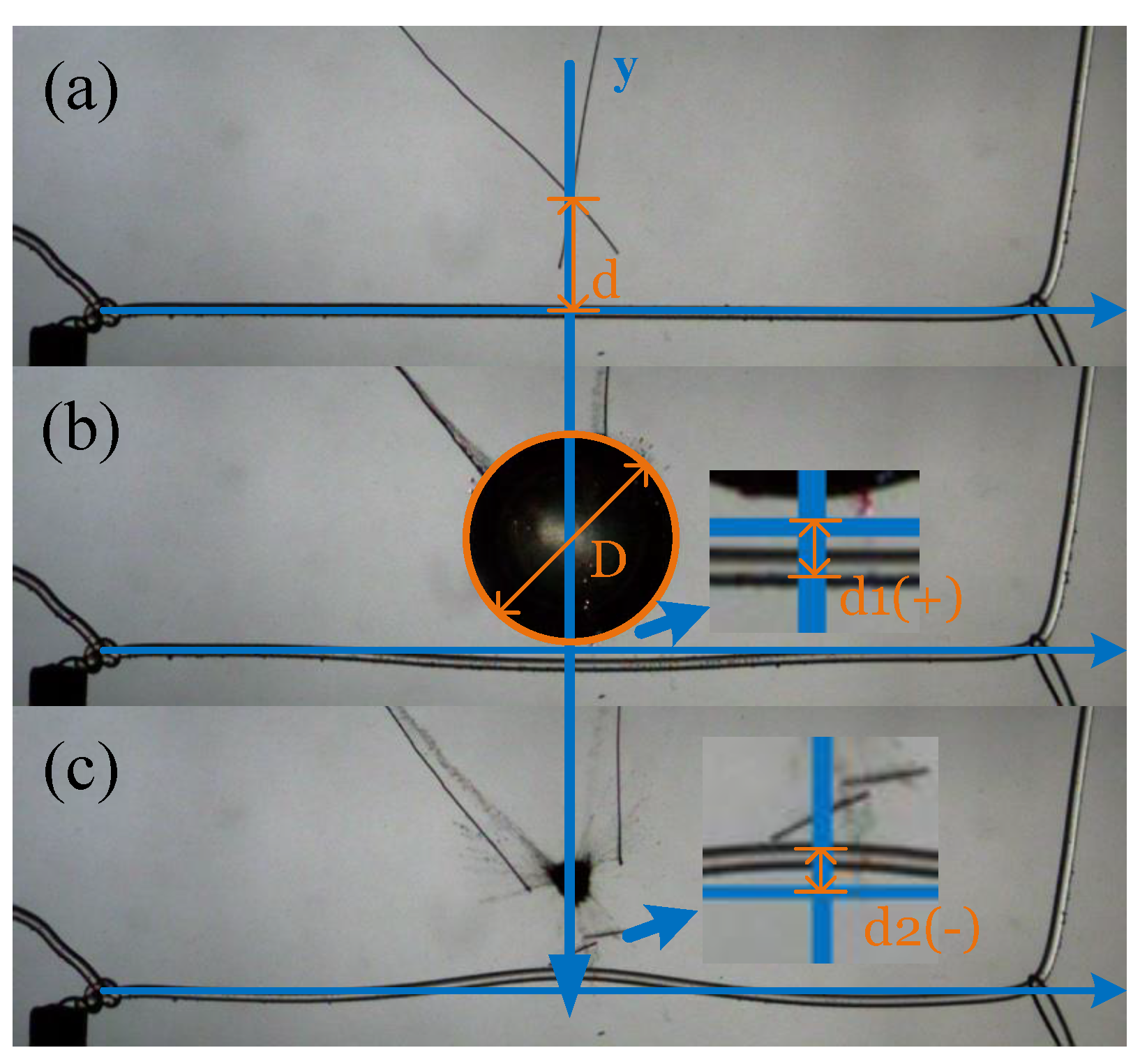
3.3.1. Model of Elastic Cylinder Displacement
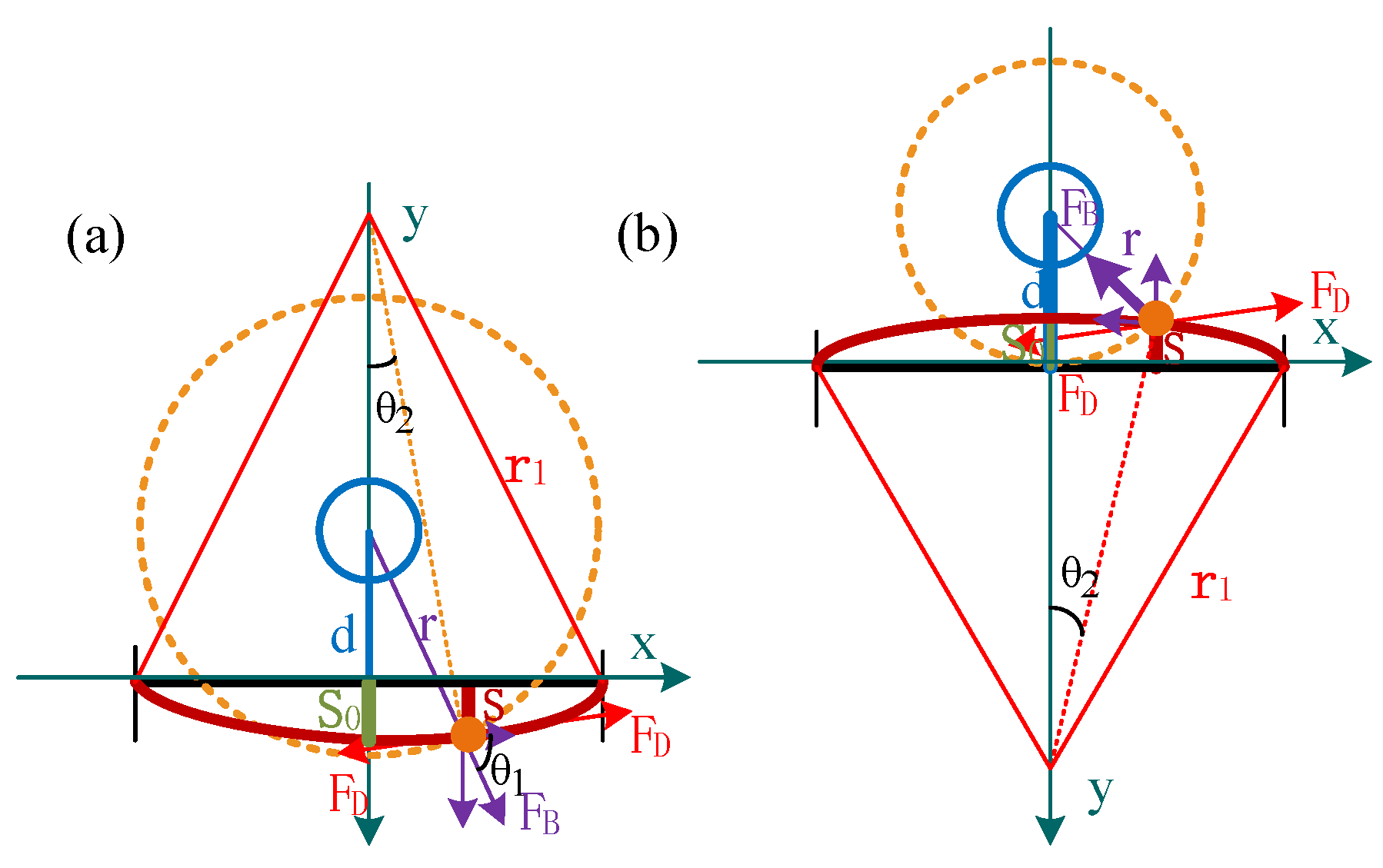
3.3.2. Force Analysis of Elastic Cylinder
3.3.3. Results on the Displacement of the Elastic Cylinder
4. Conclusions
Author Contributions
Funding
Institutional Review Board Statement
Informed Consent Statement
Data Availability Statement
Conflicts of Interest
References
- Meng, D.; Yang, S.; Yang, H.; De Jesus, A.M.; Correia, J.; Zhu, S.P. Intelligent-inspired framework for fatigue reliability evaluation of offshore wind turbine support structures under hybrid uncertainty. Ocean Eng. 2024, 307, 118213. [Google Scholar]
- Klaseboer, E.; Khoo, B.; Hung, K. Dynamics of an oscillating bubble near a floating structure. J. Fluids Struct. 2005, 21, 395–412. [Google Scholar] [CrossRef]
- Klaseboer, E.; Khoo, B.C. An oscillating bubble near an elastic material. J. Appl. Phys. 2004, 96, 5808–5818. [Google Scholar]
- Ong, G.P.; Khoo, B.C.; Turangan, C.; Klaseboer, E.; Fong, S.W. Behavior of Oscillating Bubbles Near Elastic Membranes: An Experimental and Numerical Study. Mod. Phys. Lett. B 2005, 19, 1579–1582. [Google Scholar] [CrossRef]
- Fong, S.W.; Klaseboer, E.; Turangan, C.K.; Khoo, B.C.; Hung, K.C. Numerical analysis of a gas bubble near bio-materials in an ultrasound field. Ultrasound Med. Biol. 2006, 32, 925–942. [Google Scholar] [PubMed]
- Zhang, A.; Yao, X.; Li, J. The interaction of an underwater explosion bubble and an elastic–plastic structure. Appl. Ocean. Res. 2008, 30, 159–171. [Google Scholar] [CrossRef]
- Ohl, S.W.; Klaseboer, E.; Khoo, B.C. The dynamics of a non-equilibrium bubble near bio-materials. Phys. Med. Biol. 2009, 54, 6313. [Google Scholar]
- Yu, Q.; Xu, Z.; Zhao, J.; Zhang, M.; Ma, X. PIV-based acoustic pressure measurements of a single bubble near the elastic boundary. Micromachines 2020, 11, 637. [Google Scholar] [CrossRef]
- Dular, M.; Poar, T.; Zevnik, J.; Petkovek, R. High speed observation of damage created by a collapse of a single cavitation bubble. Wear 2019, 418–419, 13–23. [Google Scholar] [CrossRef]
- Sieber, A.; Preso, D.; Farhat, M. Cavitation bubble dynamics and microjet atomization near tissue-mimicking materials. Phys. Fluids 2023, 35, 027101. [Google Scholar] [CrossRef]
- Han, L.; Hao, L.; Zhu, J.; Zhang, M.; Huang, B. Interaction of a single bubble and an elastic plate: Influence of the standoff distance. Phys. Fluids 2023, 35, 027107. [Google Scholar] [CrossRef]
- Brujan, E.A.; Nahen, K.; Schmidt, P.; Vogel, A. Dynamics of laser-induced cavitation bubbles near an elastic boundary. J. Fluid Mech. 2001, 433, 251–281. [Google Scholar] [CrossRef]
- Vogel, A.; Brujan, E.A.; Schmidt, P.; Nahen, K. Interaction of laser-produced cavitation bubbles with an elastic tissue model. In Proceedings of the Laser-Tissue Interaction XII: Photochemical, Photothermal, and Photomechanical, SPIE, San Jose, CA, USA, 21–24 January 2001; Volume 4257, pp. 167–177. [Google Scholar]
- Horvat, D.; Orthaber, U.; Schille, J.; Hartwig, L.; Löschner, U.; Vrečko, A.; Petkovšek, R. Laser-induced bubble dynamics inside and near a gap between a rigid boundary and an elastic membrane. Int. J. Multiph. Flow 2018, 100, 119–126. [Google Scholar] [CrossRef]
- Jin, Z.; Yin, C.; Chen, Y.; Hua, H. Numerical study on the interaction between underwater explosion bubble and a moveable plate with basic characteristics of a sandwich structure. Ocean Eng. 2018, 164, 508–520. [Google Scholar] [CrossRef]
- Lei, H.; Mindi, Z.; Zhenkun, T.; Guohao, H.; Biao, H. Investigation of the energy conversion process of a single bubble collapsing near different boundaries. Ocean. Eng. 2023, 277, 114063. [Google Scholar] [CrossRef]
- Li, S.; Zhang, A.M.; Han, R. Counter-jet formation of an expanding bubble near a curved elastic boundary. Phys. Fluids 2018, 30, 121703. [Google Scholar] [CrossRef]
- Klaseboer, E.; Turangan, C.K.; Khoo, B.C. Dynamic behaviour of a bubble near an elastic infinite interface. Int. J. Multiph. Flow 2006, 32, 1110–1122. [Google Scholar] [CrossRef]
- Turangan, C.K.; Ong, G.P.; Klaseboer, E.; Khoo, B.C. Experimental and numerical study of transient bubble-elastic membrane interaction. J. Appl. Phys. 2006, 100, 054910. [Google Scholar] [CrossRef]
- Ma, X.; Wang, C.; Huang, B.; Wang, G. Application of two-branch deep neural network to predict bubble migration near elastic boundaries. Phys. Fluids 2019, 31, 102003. [Google Scholar] [CrossRef]
- Ma, X.; Huang, B.; Zhao, X.; Wang, Y.; Chang, Q.; Qiu, S.; Fu, X.; Wang, G. Comparisons of spark-charge bubble dynamics near the elastic and rigid boundaries. Ultrason. Sonochemistry 2018, 43, 80–90. [Google Scholar] [CrossRef]
- Orthaber, U.; Petkovšek, R.; Schille, J.; Hartwig, L.; Hawlina, G.; Drnovšek-Olup, B.; Vrečko, A.; Poberaj, I. Effect of laser-induced cavitation bubble on a thin elastic membrane. Opt. Laser Technol. 2014, 64, 94–100. [Google Scholar]
- Turangan, C.K.; Khoo, B.C. Transient bubble oscillations near an elastic membrane in water. J. Phys. Conf. Ser. 2015, 656, 012040. [Google Scholar]
- Turangan, C.; Ball, G.; Jamaluddin, A.; Leighton, T. Numerical studies of cavitation erosion on an elastic–plastic material caused by shock-induced bubble collapse. Proc. R. Soc. Math. Phys. Eng. Sci. 2017, 473, 20170315. [Google Scholar] [CrossRef]
- Wang, A.; Zhong, Y.; Wang, G.; Huang, J.; Wang, J.; Wang, Y. Experimental study on the formation of two axial jets of cavitation bubbles near soft membranes with different thicknesses. Aip Adv. 2022, 12, 095023. [Google Scholar] [CrossRef]
- Gong, S.; Goh, B.; Ohl, S.W.; Khoo, B.C. Interaction of a spark-generated bubble with a rubber beam: Numerical and experimental study. Phys. Rev. E 2012, 86, 026307. [Google Scholar]
- Meng, D.; Yang, H.; Yang, S.; Zhang, Y.; Jesus, A.M.D.; Correia, J.; Fazeres-Ferradosa, T.; Macek, W.; Branco, R.; Zhu, S.P. Kriging-assisted hybrid reliability design and optimization of offshore wind turbine support structure based on a portfolio allocation strategy. Ocean. Eng. 2024, 295, 116842. [Google Scholar]
- Yang, S.; Meng, D.; Yang, H.; Luo, C.; Su, X. Enhanced soft Monte Carlo simulation coupled with support vector regression for structural reliability analysis. Proc. Inst. Civ. Eng.-Transp. 2024, 1–16. [Google Scholar]
- Gou, Y.; Shi, D.; Wang, J. Modeling and Reliability Evaluation of the Motion and Fluid Flow Characteristics of Spark Bubbles in a Tube. Appl. Sci. 2025, 15, 2569. [Google Scholar] [CrossRef]


| Experimenters | Materials |
|---|---|
| Dular [9] | Aluminum foil |
| Brujan [12,13] | Polyacrylamide (PAA) gel |
| Darja Horvat [14] | Polymethyl methacrylate and polyethylene |
| A. B. Sieber [10] | Agarose hydrogel |
| Ao Wang [25] | Ecoflex |
| Gong SW & Goh [26] | Rubber |
| 50 g | 100 g | 150 g | 200 g | 300 g | 400 g | |
|---|---|---|---|---|---|---|
| 0.4 mm | ✓ | ✓ | ✓ | |||
| 0.8 mm | ✓ | ✓ | ✓ | |||
| 1.2 mm | ✓ | ✓ | ✓ | |||
| 2.0 mm | ✓ | ✓ | ✓ |
| Dimensionless Parameters | Based on | Letters | Corresponding Formula |
|---|---|---|---|
| Elastic cylinder radius | |||
| distance | |||
| density | |||
| velocity | |||
| time |
Disclaimer/Publisher’s Note: The statements, opinions and data contained in all publications are solely those of the individual author(s) and contributor(s) and not of MDPI and/or the editor(s). MDPI and/or the editor(s) disclaim responsibility for any injury to people or property resulting from any ideas, methods, instructions or products referred to in the content. |
© 2025 by the authors. Licensee MDPI, Basel, Switzerland. This article is an open access article distributed under the terms and conditions of the Creative Commons Attribution (CC BY) license (https://creativecommons.org/licenses/by/4.0/).
Share and Cite
Gou, Y.; Shi, D.; Wang, J. Study on Cavitation Effects in Elastic Cylinder Displacement and Bubble Morphology: Modeling, Reliability, and Behavioral Analysis. Appl. Sci. 2025, 15, 3979. https://doi.org/10.3390/app15073979
Gou Y, Shi D, Wang J. Study on Cavitation Effects in Elastic Cylinder Displacement and Bubble Morphology: Modeling, Reliability, and Behavioral Analysis. Applied Sciences. 2025; 15(7):3979. https://doi.org/10.3390/app15073979
Chicago/Turabian StyleGou, Yuxin, Dongyan Shi, and Jiuqiang Wang. 2025. "Study on Cavitation Effects in Elastic Cylinder Displacement and Bubble Morphology: Modeling, Reliability, and Behavioral Analysis" Applied Sciences 15, no. 7: 3979. https://doi.org/10.3390/app15073979
APA StyleGou, Y., Shi, D., & Wang, J. (2025). Study on Cavitation Effects in Elastic Cylinder Displacement and Bubble Morphology: Modeling, Reliability, and Behavioral Analysis. Applied Sciences, 15(7), 3979. https://doi.org/10.3390/app15073979