Article

Numerical Study of Cavitating Flows in an External Gear Pump with Special Emphasis on Thermodynamic Effects

1
School of Mechanical Engineering, Beijing Institute of Technology, Beijing 100081, China
2
College of Transportation Engineering, Tongji University, Shanghai 201804, China
3
School of Engineering and Design, Technical University of Munich, 80333 Munich, Germany
4
School of Mechanical Engineering, Beijing Institute of Technology, Chongqing Innovation Center, Chongqing 401120, China
*
Author to whom correspondence should be addressed.
Appl. Sci. 2025, 15(7), 3529; https://doi.org/10.3390/app15073529
Submission received: 24 February 2025 / Revised: 18 March 2025 / Accepted: 20 March 2025 / Published: 24 March 2025
(This article belongs to the Section Fluid Science and Technology)

Abstract

:
Cavitation is a critical phenomenon in hydraulic systems, particularly in gear pumps, where it can significantly affect performance and reliability. This study uses numerical simulations with the Full Cavitation Model and k-ε turbulence model to investigate the thermodynamic effects of cavitation in gear pump lubricating oil at varying temperatures. It focuses on the formation and evolution of cavitation vortex structures in the outlet bridge area. The simulations reveal significant heat exchange between liquid and vapor phases, causing a local temperature drop and a reduction in saturated vapor pressure, which suppresses cavitation development. As temperature increases, this effect diminishes due to the lower density of the hydraulic oil.

1. Introduction

The external gear pump is widely employed in hydraulic transmission systems. Being a critical component of such systems, its stable operation directly impacts their performance. Unfortunately, the efficiency of external gear pumps can be significantly compromised by cavitation phenomena. Cavitation is a dynamic phase-change event that takes place in liquids when the local static pressure drops below the saturated vapor pressure. The unsteady nature of cavitation flow encompasses a range of complex phenomena, including the formation, development, fracturing, shedding, and eventual collapse of cavities. These unsteady processes disrupt and influence the internal flow field within the external gear pump.
As cavitation within the pump intensifies, the increase in the volume fraction of gas in the fluid results in a reduction in the fluid’s compressibility, ultimately diminishing the efficiency of the hydraulic transmission system. Moreover, the collapse of cavity bubbles releases energy. When these bubbles collapse against the external gear’s surface, the energy release generates pressure waves that impact the gear wall. This, in turn, leads to damage to the wall material and the formation of numerous closely spaced small holes [1,2,3,4,5]. As these small holes gradually expand into voids, the structural integrity of the gear becomes seriously compromised, thereby reducing the reliability of the external gear pump.
To mitigate the adverse effects of cavitation on the external gear pump, it is imperative to analyze the unsteady cavitation processes, including the extent of cavitation, the duration of cavitation fluctuations, and the proportion of cavitation bubbles in the fluid. Additionally, it is crucial to acknowledge that the working conditions of gear pumps can vary, with one of the most influential parameters being fluctuations in fluid temperature.
Hydraulic oil is the predominant fluid utilized in gear pumps, and its characteristics are notably sensitive to temperature variations, including density, dynamic viscosity, and saturated vapor pressure. These inherent physical properties exert a significant influence on the cavitation process occurring within the external gear pump. As the liquid undergoes vaporization, it absorbs its latent heat of vaporization, resulting in a temperature difference between the forming bubbles and the surrounding liquid during the cavitation process. This phenomenon significantly shapes the formation and development of cavitation, referred to as the cavitation thermodynamic effect. It is worth noting that the physical properties of hydraulic oil play a pivotal role in this thermodynamic cavitation effect [6,7,8].
The thermodynamic effect of cavitation has been studied by many researchers. Franc et al. [9] investigated the cavitation instabilities of refrigerant R-114 at three different fluid temperatures. They found that the onset of blade cavitation is delayed at a higher reference temperature. Cervone et al. [10] carried out cavitation experiments in water around a NACA 0015 hydrofoil at various cavitation numbers and free-stream temperatures (from 298 K to 343 K) to investigate the characteristics of cavitation instabilities and the impact of thermodynamic effects. It is found that for the same cavitation number, the cavity tends to become thicker and longer at higher freestream temperatures. Gustavsson et al. [11] conducted experiments of cavitating flow around NACA0015 hydrofoil with water and fluoroketone, respectively. They found that at the same cavitation number, the cavity length of fluoroketone was shorter than that of water, and the thermodynamic effect of cavitation was more obvious. Petkovšek et al. [12] took the Venturi tube as the experimental model and carried out the cavitation test of high-temperature water passing through the Venturi tube and recorded the average temperature of the cavitation flow field and the temperature distribution in the flow field with an infrared camera.
Due to the limitations of the measurement techniques, various numerical methods have been developed to investigate the cavitating flows. The accuracy of the cavitation model is significant in the cavitation process simulation. Hosangadi and Ahuja [13] employed a transport-based cavitation model to simulate cavitating flows in liquid nitrogen and hydrogen. Huang et al. [14] validated a thermodynamic cavitation model based on the simplified Rayleigh–Plesset equation. They calibrated the parameters of the cavitation model for liquid hydrogen cavitating flows and came to a similar result to that of Hosangadi and Ahuja [13]. Rodio et al. [15] modified the Rayleigh–Plesset equation by adding a term of convective heat transfer at the interface between the liquid and the bubble (Eulerian multiphase model) coupled with a bubbly flow model. It is found that the modified cavitation model can accurately predict the thermodynamic effect in cavitating flows in a shock tube and two-phase expansion tube. Liu et al. [16] provided a mixture model with modified mass transfer expression based on the mechanics of evaporation and condensation for calculating cavitating flow, and this cavitation model was further developed to predict cavitating flows in high-temperature water by considering the thermodynamic effects and physical properties [17]. It is found that the length of the vapor distribution decreases with temperature increasing, and the prediction of the axial vapor fraction is in good agreement with the experimental data.
Oil cavitation is adverse to the hydraulic system and its components. When cavitation occurs, the oil enters a gas–liquid two-phase state. This changes the physical properties of the hydraulic oil and affects the dynamic characteristics and stability of the whole hydraulic system. The existence of a gas phase reduces the efficiency, the actual transport capacity, and the quality of outlet flow of the positive displacement pump. As the cavitation develops, the energy generated by the growth and collapse of the bubble greatly impacts the hydraulic system, causing pressure fluctuations in the hydraulic system. The entire hydraulic system can be seriously damaged under certain conditions. In order to improve the stability of the gear pump, it is significant to investigate the cavitation phenomenon in the gear pump.
The study of Computational Fluid Dynamics (CFD) numerical simulations for gear pumps can be traced back to 1989 when Manco et al. [18] proposed a detailed simulation program to investigate the performance of external gear pumps. Building on this foundation, Campo et al. [19] introduced a simplified two-dimensional numerical approach to study the effect of cavitation on the volumetric efficiency of external gear pumps. More recently, Mithun et al. [20] developed a three-phase compressible model combined with an immersed boundary approach to predict cavitation in gear pumps, particularly in the presence of non-condensable gases (NCG). Yoon et al. [21] utilized the Immersed Solid Method (ISM) to simulate the operation of a gear pump under extreme conditions of high rotational speed, focusing on the effect of lateral clearance on flow rate. Choudhuri et al. [22] employed numerical methods to examine how the number of teeth affects the operation of a gear pump. Additionally, Bilalov et al. [23] proposed a numerical model based on ANSYS CFX to study the impact of cavitation on the power consumption rate of gear pumps.
In addition to gear pumps, there have been numerous CFD numerical simulation studies focusing on other systems where lubricating oil serves as the working medium. For instance, Amirante et al. [24] combined experimental and numerical analyses to evaluate the effects of cavitation on hydraulic proportional directional valves. Casoli et al. [25,26] developed a one-dimensional fluid dynamic model of a damper, focusing on the influence of cavitation on the pressure distribution generated by textured surfaces in lubricated couplings of hydraulic machines. Tacconi et al. [27] established a numerical model to support the analysis and future design of hybrid journal bearings for fuel pump applications. Casari et al. [28] numerically investigated pressure pulsations and cavitation phenomena in a micro-Organic Rankine Cycle (m-ORC) system, with a particular focus on the behavior of the pumping system. Furthermore, Li et al. [29] proposed an improved cavitation model incorporating thermodynamic effects, which is particularly relevant for ORC systems operating under varying thermal conditions.
The cavitation dynamics of pumps and the numerical calculations of polymeric fluids have been deeply investigated in the past few decades. However, many polymeric fluids such as hydraulic oil and lubricating oil have different physical properties from room-temperature water. Their thermodynamic effects and the specific influence of thermo-sensitive physical properties on cavitation dynamics in a wide range of temperatures are still not well understood.
The objectives of this paper are (1) to obtain the cavitation characteristics of hydraulic oil L-HM46 in the external gear pump, (2) to study the influence of temperature change on the cavitation characteristics in the external gear pump, and (3) to investigate the thermodynamic effect on cavitation of hydraulic oil in the external gear pump.

2. Materials and Methods

2.1. Numerical Calculation Models

2.1.1. Governing Equations

A numerical simulation was established based on the homogeneous multiphase flow model, which treats the gas–liquid mixture as a homogeneous medium. Both phases share the same pressure, velocity, and temperature. The continuity, momentum, enthalpy, and transport equations in the Cartesian coordinate system are as follows [30]:
ρ m t + ρ m U j x j = 0
ρ m U i t + ρ m U i U j x j = p x i + x j μ m + μ t u r U i x j + U j x i 2 3 u k x k δ i j
t ρ m h + f v L e v + x j ρ m U j h + f v L e v = x j μ m P r l a m + μ t u r P r t u r h m x j
ρ l α l t + ρ l α l U j x j = m + + m
where the mixture density and the mixture laminar viscosity are shown as:
ρ m = ρ l 1 α v + ρ v α v
μ m = μ l 1 α v + μ v α v
In the above equations, ρm is the mixture density. ρl and ρv are the liquid and vapor density, respectively. αl and αv are the liquid fraction and the vapor fraction, respectively. U is the velocity; p is the pressure; μm is the mixture laminar viscosity; l and v are the liquid and vapor dynamic viscosities, respectively; and μtur is the turbulent viscosity. f is the mass volume fraction, Lev is the latent heat, h is the enthalpy, and Prtur and Prlam are the turbulent and laminar Prandtl numbers, respectively. The subscripts (i, j, k) denote the directions of the Cartesian coordinates, and the subscript m denotes the mixture phase. The source term m+ and the sink term m in Equation (4) represent the condensation and evaporation rates, respectively.

2.1.2. Cavitation Model

The Full Cavitation Model (FCM), proposed by Singhal et al. [31], serves as a practical and comprehensive model for predicting the performance of engineering equipment in cavitating flows. Within this model, the growth and collapse of a bubble cluster are determined with the Rayleigh–Plesset equation, which governs bubble dynamics. Furthermore, it considers the effects of turbulence-induced pulsations in bubble transport, pressure, and velocity. The rates of vaporization and condensation are as follows:
m = C e k S ρ l ρ v 2 3 P v P ρ l 1 f v
m + = C c k T ρ l ρ v 2 3 P P v ρ l f v
where ƒv is the vapor mass fraction, k is the turbulent kinetic energy, S is the surface tension, and the two empirical coefficients are Ce = 0.02, Cc = 0.01 [32].

2.1.3. Turbulence Model
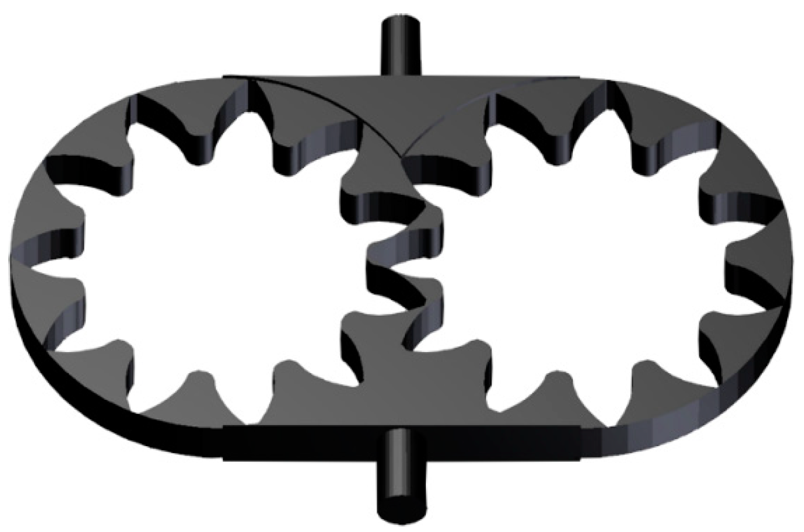
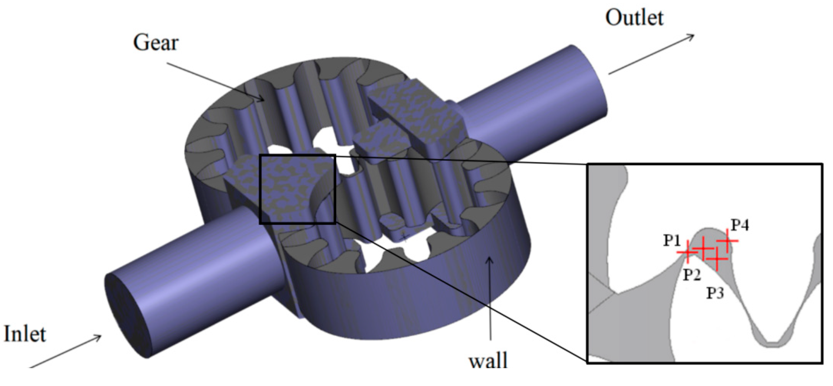
The standard k-ɛ model [33], a widely used two-equation RANS model known for its strong applicability, characterizes turbulence viscosity μt by turbulent kinetic energy k and turbulent dissipation rate ɛ. The governing equations of the standard k-ɛ model are as follows:
ρ k t + ρ k u j x j = x j μ + μ t σ k k x j + G k ρ ε
ρ ε t + ρ ε u j x j = x j μ + μ t σ ε ε x j + C ε 1 ε k G k C ε 2 ρ ε 2 k
The turbulent viscosity coefficient μt is defined as:
μ t = ρ C μ k 2 ε
where Gk is the turbulent kinetic energy term, ρ is the fluid density, uj is the component of gas velocity, and μ is the laminar viscosity. The assumed model constants are σk = 1.0, σε = 1.3, σε1 = 1.44, σε2 = 1.92, and Cμ = 0.09 [34].

2.2. Pump Geometry

CB series gear pumps are positive displacement external gear pumps, featuring gears with an involute tooth shape [35]. This pump offers several advantages, including a simple structure, low noise, smooth oil transmission, excellent self-priming performance, reliable operation, and a long service life. They have found extensive application in low-pressure hydraulic transmission systems for machine tools, oil supply, and cooling systems in large mechanical equipment, as well as lubrication systems for various mechanical equipment.
In this paper, a commercial CB gear pump serves as the numerical model. Both the driving gear and driven gear feature involute tooth profiles. The computational domain is involute tooth profiles. The computational domain is illustrated in Figure 1, and the key geometric parameters are outlined in Table 1.

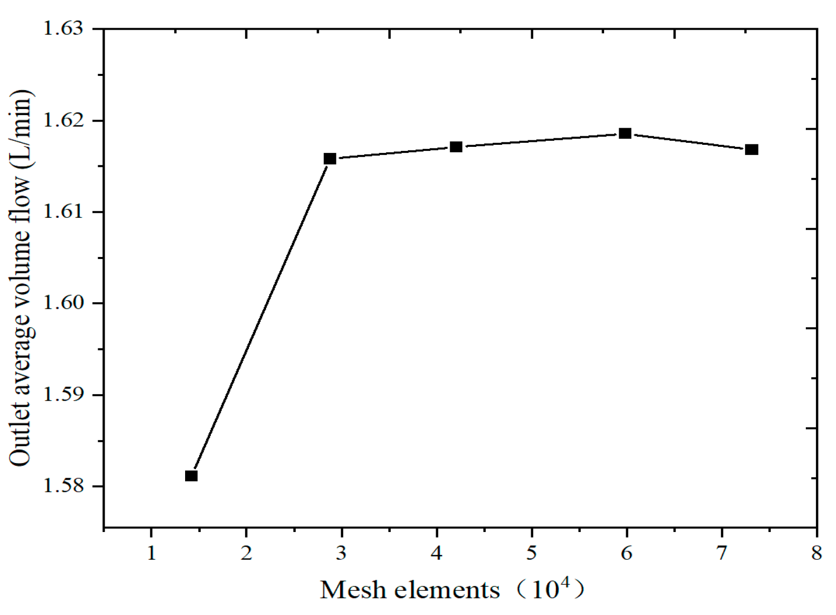
2.3. Numerical Setup and Validation

Numerical calculations were performed using the commercial software PumpLinx 4.6.0. The numerical scheme is based on the finite volume method (FVM), employing a second-order upwind scheme for spatial discretization and an implicit solver to enhance stability and computational efficiency. The computational domain and monitoring points in the flow field are shown in Figure 2. In the simulation, the gears and boundaries are modeled as adiabatic slip walls. The boundary conditions consist of a pressure inlet and a pressure outlet. To ensure that the cavitation phenomenon in the simulation is not influenced by boundary conditions, the cavitation number is kept constant, eliminating the impact of factors other than temperature on cavitation.
The cavitation number is used to characterize the degree of cavitation, as shown in Equation (12).
σ c = p i n p v 0.5 ρ l U 2
where Pin is the inlet pressure of the gear pump, and pv is the saturated vapor pressure. ρl is the density of the fluid at that temperature. U is the pitch line velocity.
The cavitation number at 333.15 K is adopted as the reference value. Due to the properties of the medium, the saturated vapor pressure of the oil changes with temperature, so achieving the same cavitation number at different temperatures requires different pressures. The working conditions of the external gear pump are detailed in Table 2.
For the gear pump simulation, the grid was generated using PumpLinx’s automatic grid generation tool, which utilizes Cartesian grids with local grid refinement to accurately capture complex flow features. PumpLinx includes dynamic mesh templates for gear pumps and utilizes the sliding mesh method to model the motion of the gears.
This paper focuses on investigating the evolution of the internal flow field and cavitation phenomena within the gear pump. The internal flow dynamics and cavitation within the gear pump are intricately tied to the pump’s flow rate. Consequently, the outlet volume flow is selected to assess grid independence in this section. Figure 3 illustrates the values of outlet average volume flow in the gear pump with varying total mesh elements. When the grid count exceeds 400,000, further increasing the number of grids has minimal impact on the flow. Hence, the total grid count is set at 420,000. To further ensure the reliability of the grid independence study, the Grid Convergence Index (GCI) was employed. The GCI quantifies the uncertainty associated with the discretization error and provides a measure of how much the solution changes with grid refinement [36]. As shown in Table 3, the calculated GCI values for the selected grid sizes were found to be less than 3%, which is within acceptable limits. This confirms that the chosen grid resolution of 420,000 elements is sufficient to accurately capture the flow characteristics.
The results obtained through numerical calculations are compared with the experimental findings [37]. As illustrated in Figure 4, the vortex structure is distinctly visible through the streamline direction in the numerical results, aligning with the experimental outcomes. This indicates that the numerical calculation method can precisely forecast the gear pump’s internal flow field. These results furnish dependable data support and a theoretical foundation for future research.

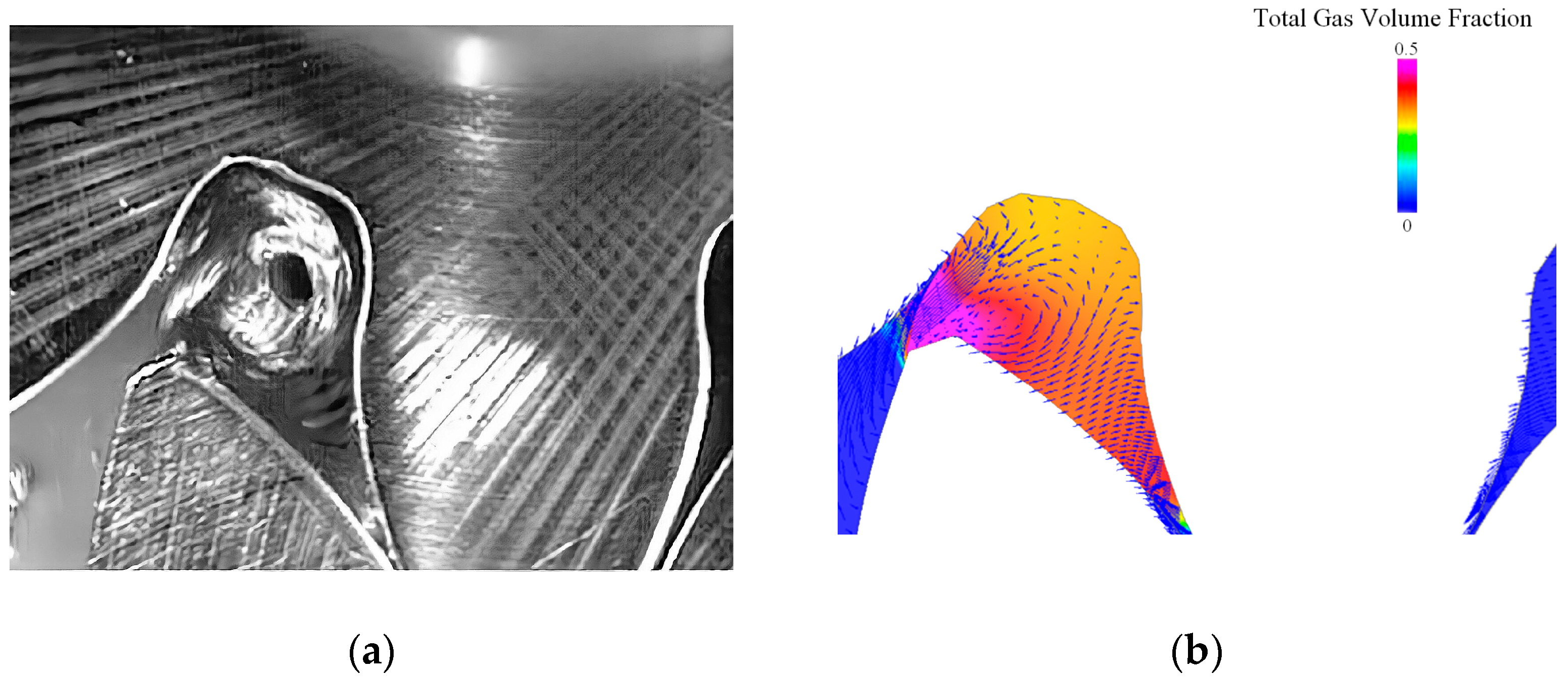
3. Results and Discussion

As the gear pump rotates, the rapid volume changes within the displacement chamber continuously compress and propel the liquid. This drastic change can easily lead to transition flow. Five moments are selected, as shown in Figure 5 (T1 = 0.1825 s, ΔT = 365 μs). The periodic evolution of cavitation at P2 (333.15 K) is shown in Figure 6. Comparing the volume of tooth tip gaps on the right, it can be seen from the pressure contour in Figure 6 at time T1 that pressure in the area where point P2 is located decreases due to the increase in cavity volume during rotation, leading to the occurrence of cavitation in the form of a vortex. It can be seen from Figure 6 at T1 and T2 that the volume of the cavitation area increases. Significant pressure fluctuations are evident on the contour at the meshing point, leading to leakage flow across these two narrow cross-sections. Additionally, as the gear pump continues to rotate at T3, T4, and T5, the two teeth disengage from the meshing area. Inlet hydraulic oil enters the cavitation area, resulting in increased pressure within this region and subsequent cavity collapse.
Figure 7 shows the variations of temperature, velocity, and gas volume fraction at different positions at 303.15 K. The gas volume fraction and temperature change almost synchronously. Cavitation is a transition between liquid and gas, accompanied by the absorption and release of heat. When cavitation occurs, the gas volume fraction increases. The liquid absorbs heat from the surrounding fluid, resulting in a temperature increase. Conversely, when cavity collapse occurs, the gas volume fraction decreases, and the liquid releases heat to the surrounding fluid, causing a temperature drop. However, it can be seen in the curves that as the temperature approaches its lowest point, a small fluctuation consistently occurs, initially increasing and then decreasing. This phenomenon is particularly pronounced in Figure 7b,c. During the rotation of the gear pump, the volume and pressure inside the chamber continuously change. This rapid and vigorous fluctuation can readily induce cavitation and the rapid emergence of leakage flows within narrow gaps, ultimately resulting in the formation of a vortex.

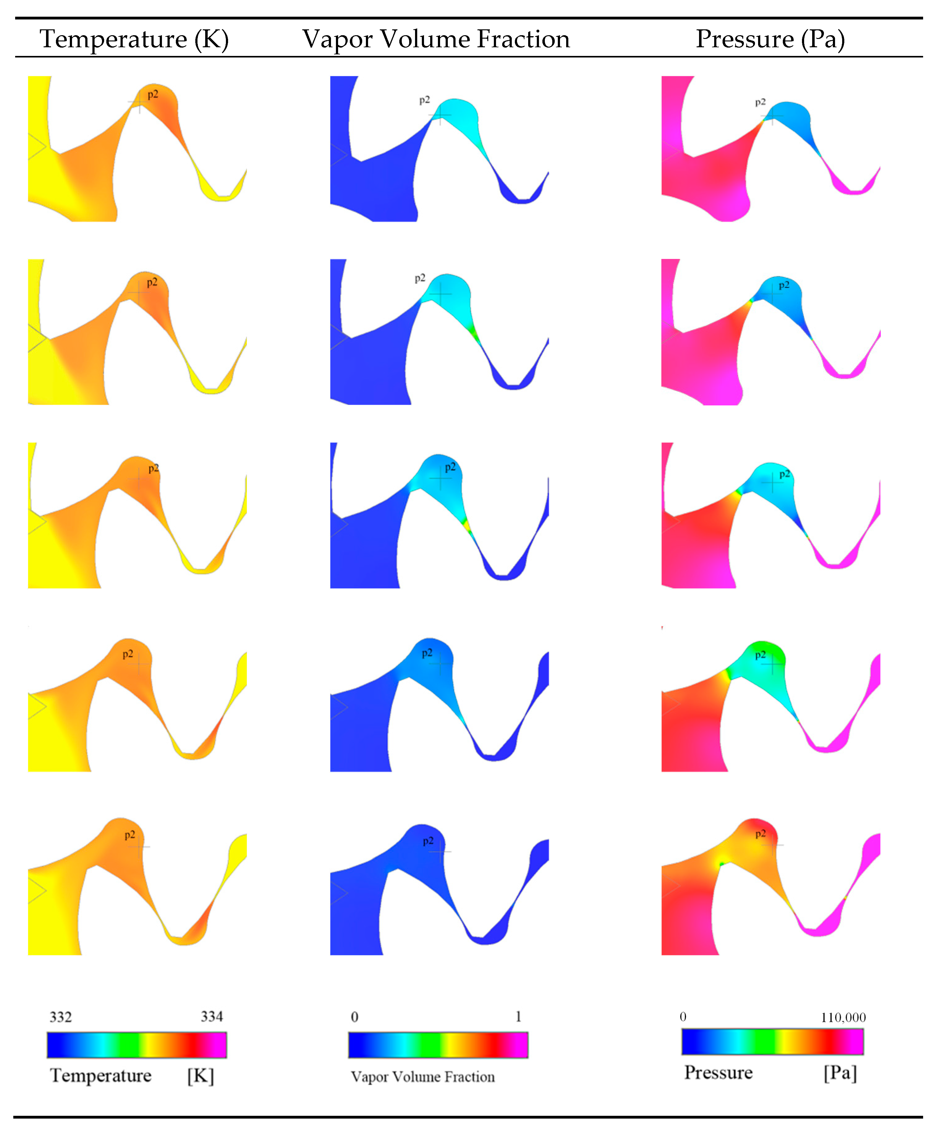
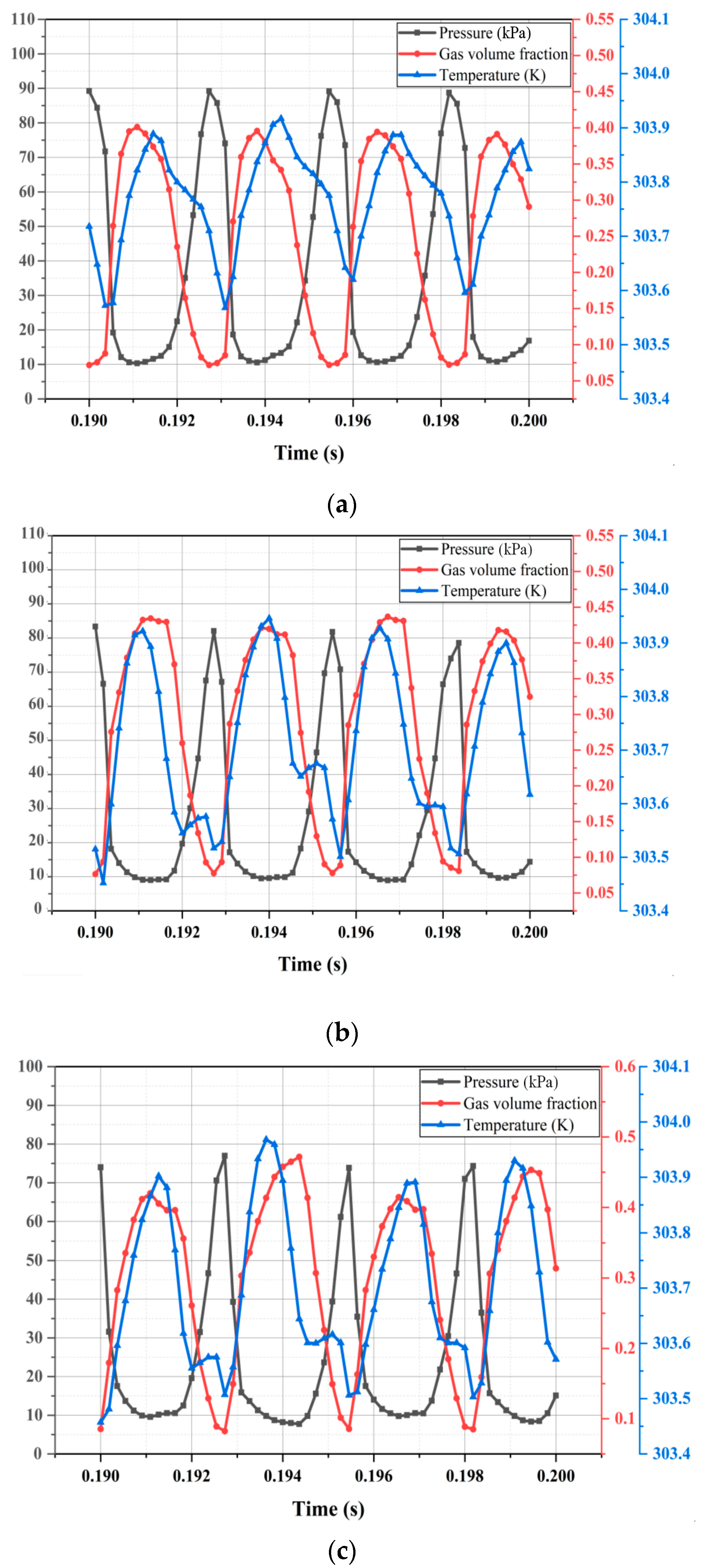
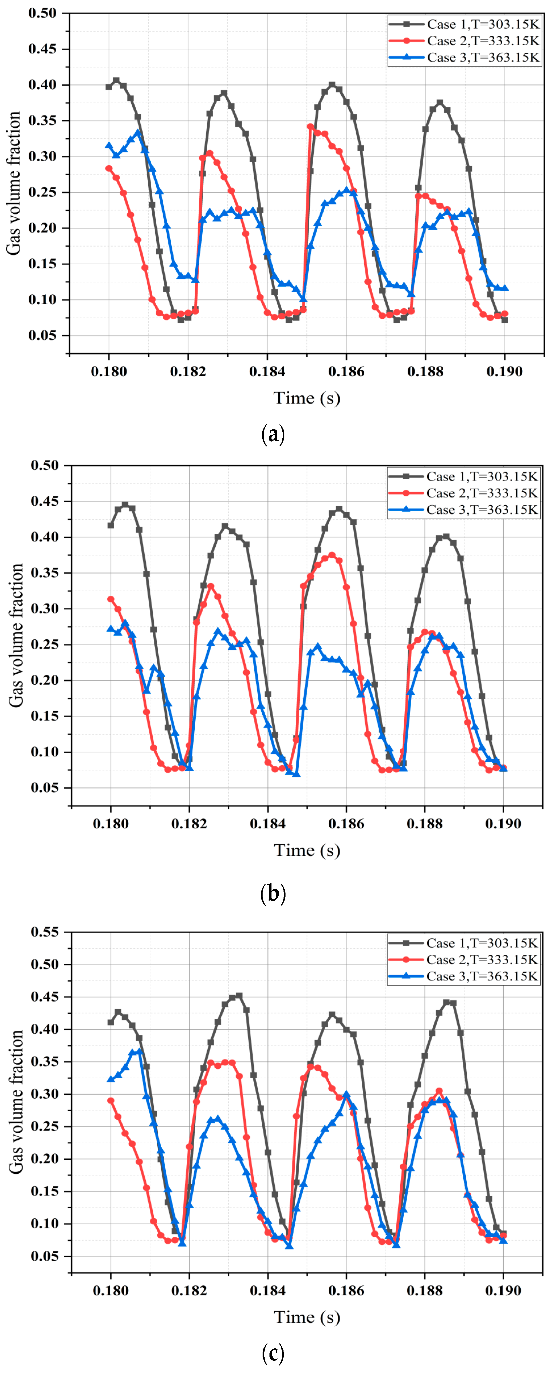
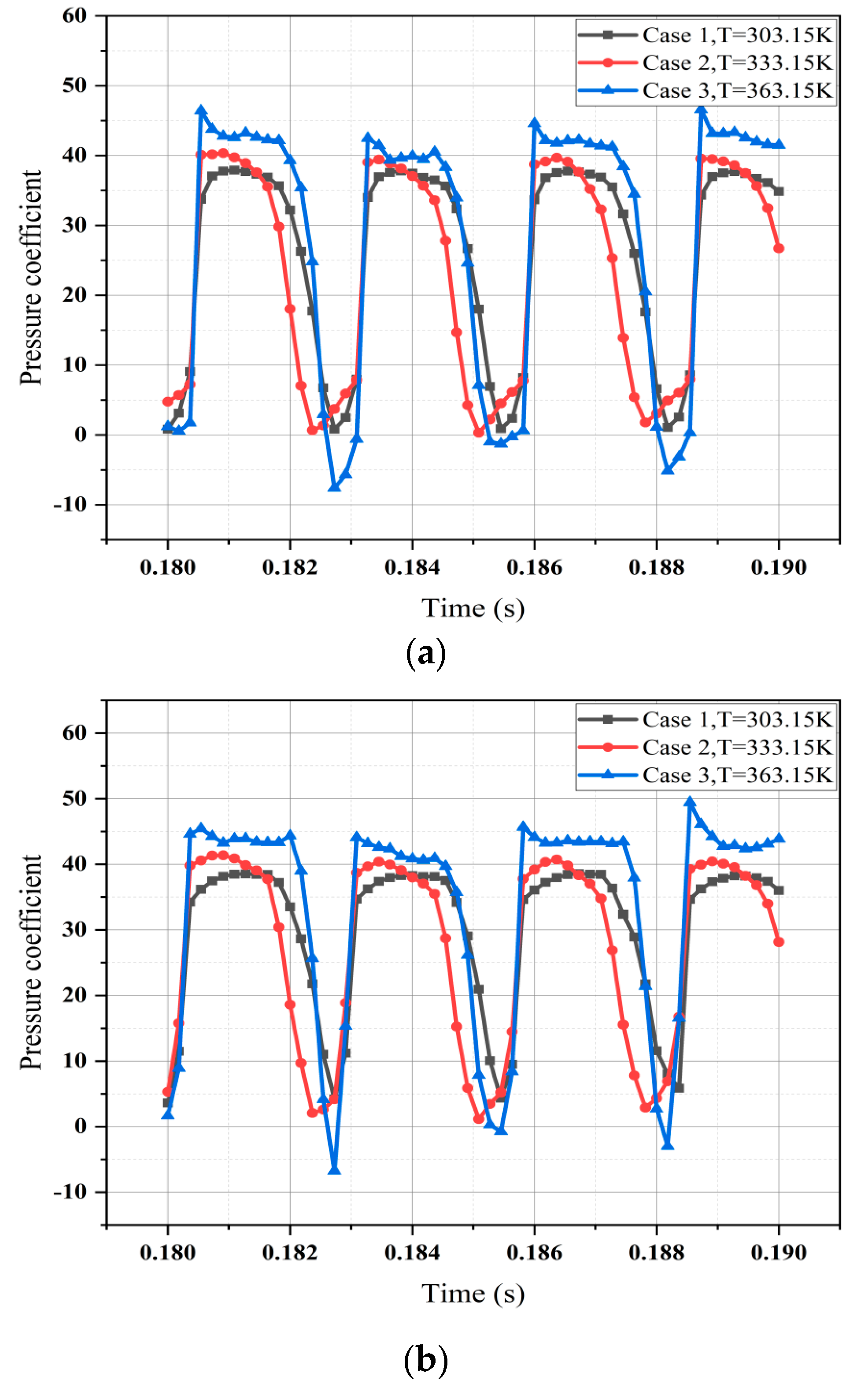
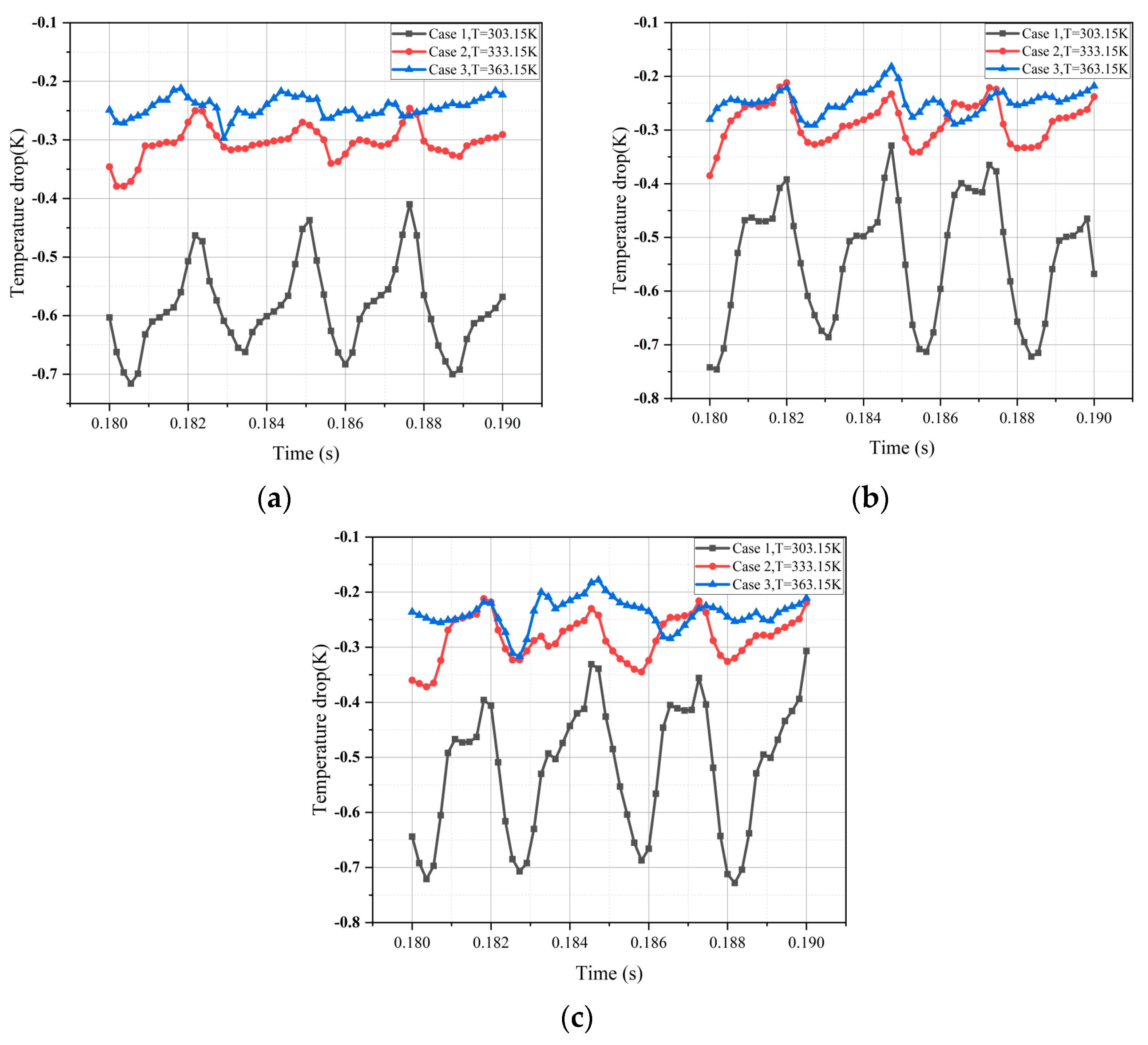
Thermodynamic Effects of Cavitation at Different Temperatures

The inlet cavitation number is maintained at a constant to analyze the influence of temperature on cavitation dynamics. The evolution of cavities at different temperatures is shown in Figure 8. The cavitation phenomena at each point exhibit significant fluctuations and generally display a diminishing trend with increasing temperature. Consequently, it is evident that higher temperatures inhibit cavitation development.
The pressure coefficient, a dimensionless number, characterizes the relative pressure across the entire flow field, which is shown in Equation (13).
C p = p p 0.5 ρ l U 2
p is the pressure of the flow field at infinity (referring to inlet pressure in this paper). p is the local pressure. ρl is the density of the fluid. U is the velocity of the incoming flow at infinity (refers to the gear top linear speed in this paper).
Pressure coefficients at P2, P3, and P4 at different temperatures are shown in Figure 9. The range of pressure coefficient fluctuation at each point increases with rising temperature. In other words, as the temperature increases, the influence of the thermodynamic effect on cavitation intensifies. At 333.15 K, the pressure coefficient returns to the inlet value earlier than at 303.15 K. However, the pressure coefficient decreases more gradually at 363.15 K. This phenomenon arises from the logarithmic relationship between the saturated vapor pressure of hydraulic oil and temperature. The change is more pronounced in the temperature range of 333.15 K to 363.15 K compared to that in the range of 303.15 K to 333.15 K. This suggests that the thermodynamic effect is more prominent at 363.15 K. Consequently, cavitation is more effectively suppressed at higher temperatures, as evidenced by the gas volume fraction in Figure 9. This delay in cavitation suppression results in a later decrease in the pressure coefficient at higher temperatures. Similarly, due to the heightened cavitation suppression at higher temperatures, the pressure coefficient recovers more rapidly after reaching its lowest point with increasing temperature.
The temperature distribution characteristics of three points P2, P3, and P4 are analyzed by their temperature drop in Figure 10. It can be seen that the temperature drop is minimum at 363 K with an average temperature drop of 0.265 K and the minimum frequency of change in one cycle. The average temperature drop is 0.291 K at 333 K. The temperature drop is maximum at 303 K with an average value of 0.563 K and the maximum frequency of change. The temperature drop at 363 K is almost twice that of 303 K.
The thermodynamic effect is characterized by the release of greater latent heat of vaporization by the liquid as temperature rises, resulting in a more substantial local temperature drop. However, in the results, an interesting observation is made: as temperature increases, the temperature drop actually decreases. It can be seen from Figure 8 that as the temperature of hydraulic oil increases, its density decreases. In a gear oil pump, the volume of the cavity is the same. A decrease in density will lead to a decrease in cavity volume fraction, as shown in Figure 8. Under a temperature of 363 K, the gas volume fraction is only 50% of 303 K. Therefore, at 363 K, the total amount of gas vaporization is small, resulting in a small total latent heat of gas vaporization and less heat absorption than 303 K. Therefore, it shows that as the temperature increases, the temperature drop decreases.

4. Conclusions

In this paper, the physical parameters of L-HM46 hydraulic oil at different temperatures are obtained. The model of the external gear pump is established. A numerical calculation method is developed based on the obtained hydraulic oil parameters, and the method is verified by a control experiment. The influence of the cavitation thermodynamic effect at different temperatures on cavitation in a gear pump is investigated. The main conclusions are as follows:
(1) In the cases presented in this article, the gear pump forms a cavitation vortex in the outlet bridge area. This phenomenon is a result of the rapid changes in chamber volume during rotation, leading to a substantial pressure difference and the emergence of swift leakage flow within the narrow gear gaps. Vortex cavitation is observed in the outlet bridge area. As the two teeth gradually move apart, the low-pressure region within the cavitation area increases. Consequently, cavitation diminishes and eventually disappears. The cavitation undergoes periodic development and alterations during the gear pump’s rotation.
(2) Comparing the result at 303 K, under the same cavitation number, the gas volume fraction decreased, and the pressure coefficient increased at 363 K, owing to the inhibitory impact of the thermodynamic effects.
(3) Thermodynamic effects cause a temperature drop, and the temperature drop becomes more pronounced as the temperature increases. However, the opposite phenomenon is observed in the calculation example: the temperature drop of the calculation example for 303 K is less than that of 363 K, which is due to the physical properties of the lubricant, and the density of the lubricant decreases as the temperature rises. In the same space in the 363 K case, the total amount of vaporization is only half of 303 K. This difference in mass results in a difference in heat release, ultimately showing a decrease in temperature drop as the temperature increases.
The realistic application of this study manifested in multiple aspects. As for the optimization of industrial machinery, this innovation can enhance the gear pump to improve its resistance to cavitation and ensure stable performance under varying operating conditions. Moreover, the decline in temperature will help reduce damage to the surface of the road. In another aspect, the principle of this study can be applied in the design of a temperature regulator, which can be used in industrial manufacturing to yield benefits for the maintenance of materials. In addition, this research can also be further deepened to study the environmental influence of cavitating flow to learn how to release the negative impact of this phenomenon.

Author Contributions

Conceptualization, X.W. and T.C.; methodology, X.W., X.Y. and T.C.; software, Y.L. and Z.L.; validation, X.W., Y.L. and Z.L.; formal analysis, X.W., Y.L., Z.L. and X.Y.; investigation, Y.L.; resources, Z.L.; data curation, X.Y.; writing—original draft preparation, X.W. and X.Y.; writing—review and editing, X.W. and Y.L.; visualization, X.W. and X.Y.; supervision, T.C.; project administration, T.C.; funding acquisition, T.C. All authors have read and agreed to the published version of the manuscript.

Funding

This work was supported by the Aviation Science Foundation (20230023072001) and the Technology Innovation Program of Beijing Institute of Technology (2023CX11004).

Institutional Review Board Statement

Not applicable.

Informed Consent Statement

Not applicable.

Data Availability Statement

The original contributions presented in this study are included in the article. Further inquiries can be directed to the corresponding author.

Conflicts of Interest

The authors declare no conflicts of interest.

References

  1. Brennen, C.E. Cavitation and Bubble Dynamics; Oxford University Press: New York, NY, USA, 1995. [Google Scholar]
  2. Kim, K.H.; Chahine, G.; Franc, J.P.; Karimi, A. (Eds.) Advanced Experimental and Numerical Techniques for Cavitation Erosion Prediction; Springer: Berlin/Heidelberg, Germany, 2014; Volume 106. [Google Scholar]
  3. Kubota, A.; Kato, H.; Yamaguchi, H. A New Modelling of Cavitating Flows: A Numerical Study of Unsteady Cavitation on a Hydrofoil Section. J. Fluid Mech. 1992, 240, 59–96. [Google Scholar] [CrossRef]
  4. Wang, G.; Senocak, I.; Shyy, W.; Ikohagi, T.; Cao, S. Dynamics of Attached Turbulent Cavitating Flows. Prog. Aerosp. Sci. 2001, 37, 551–581. [Google Scholar]
  5. Ji, B.; Luo, X.; Wu, Y.; Peng, X.; Xu, H. Partially-Averaged Navier–Stokes Method with Modified k–ε Model for Cavitating Flow Around a Marine Propeller in a Non-Uniform Wake. Int. J. Heat Mass Transfer 2012, 55, 6582–6588. [Google Scholar] [CrossRef]
  6. Chen, T.; Wang, G.; Huang, B.; Wang, K. Numerical Study of Thermodynamic Effects on Liquid Nitrogen Cavitating Flows. Cryogenics 2015, 70, 21–27. [Google Scholar]
  7. Kato, H. Temperature Depression in Cavity. In Proceedings of the ASME Symposium on Cavitation and Gas-Liquid Flow in Fluid Machinery and Devices, San Diego, CA, USA, 7–11 July 1996; ASME: New York, NY, USA, 1996; pp. 407–413. [Google Scholar]
  8. Chen, T.; Huang, B.; Wang, G.; Wang, K. Effects of Fluid Thermophysical Properties on Cavitating Flows. J. Mech. Sci. Technol. 2015, 29, 4239–4246. [Google Scholar] [CrossRef]
  9. Franc, J.P.; Rebattet, C.; Coulon, A. An Experimental Investigation of Thermal Effects in a Cavitating Inducer. J. Fluids Eng. 2004, 126, 716–723. [Google Scholar]
  10. Cervone, A.; Bramanti, C.; Rapposelli, E.; d’Agostino, L. Thermal Cavitation Experiments on a NACA 0015 Hydrofoil. Fluids Eng. 2006, 128, 326–331. [Google Scholar] [CrossRef]
  11. Gustavsson, J.P.; Denning, K.C.; Segal, C. Hydrofoil Cavitation Under Strong Thermodynamic Effect. J. Fluid Eng. 2008, 130, 091303. [Google Scholar]
  12. Petkovšek, M.; Dular, M. IR Measurements of the Thermodynamic Effects in Cavitating Flow. Int. J. Heat Fluid Flow 2013, 44, 756–763. [Google Scholar]
  13. Hosangadi, A.; Ahuja, V. A Generalized Multi-Phase Framework for Modeling Cavitation in Cryogenic Fluids. In Proceedings of the 33rd AIAA Fluid Dynamics Conference and Exhibit, Orlando, FL, USA, 23–26 June 2003; AIAA: Reston, VA, USA, 2003; p. 4000. [Google Scholar]
  14. Huang, B.; Wu, Q.; Wang, G. Numerical Investigation of Cavitating Flow in Liquid Hydrogen. Int. J. Hydrogen Energy 2014, 39, 1698–1709. [Google Scholar]
  15. Rodio, M.G.; De Giorgi, M.G.; Ficarella, A. Influence of Convective Heat Transfer Modeling on the Estimation of Thermal Effects in Cryogenic Cavitating Flows. Int. J. Heat Mass Transfer 2012, 55, 6538–6554. [Google Scholar]
  16. Liu, S.; Li, S.; Zhang, L.; Wu, Y. A Mixture Model with Modified Mass Transfer Expression for Cavitating Turbulent Flow Simulation. Eng. Comput. 2008, 25, 290–304. [Google Scholar]
  17. Chen, T.; Wang, G.; Huang, B.; Wang, K.; Xu, H. Numerical Study of Cavitating Flows in a Wide Range of Water Temperatures with Special Emphasis on Two Typical Cavitation Dynamics. Int. J. Heat Mass Transfer 2016, 101, 886–900. [Google Scholar]
  18. Manco, S.; Nervegna, N. Simulation of an External Gear Pump and Experimental Verification. Proc. JFPS Int. Symp. Fluid Power 1989, 1989, 147–160. [Google Scholar]
  19. Del Campo, D.; Castilla, R.; Raush, G.A.; Gamez Montero, P.J.; Codina, E. Numerical Analysis of External Gear Pumps Including Cavitation. J. Fluids Eng. 2012, 134, 081105. [Google Scholar]
  20. Mithun, M.G.; Koukouvinis, P.; Karathanassis, I.K.; Gavaises, M. Numerical Simulation of Three-Phase Flow in an External Gear Pump Using Immersed Boundary Approach. Appl. Math. Model. 2019, 72, 682–699. [Google Scholar]
  21. Yoon, Y.; Park, B.H.; Shim, J.; Han, Y.O.; Hong, B.J.; Yun, S.H. Numerical Simulation of Three-Dimensional External Gear Pump Using Immersed Solid Method. Appl. Therm. Eng. 2017, 118, 539–550. [Google Scholar]
  22. Choudhuri, K.; Biswas, N.; Mandal, S.K.; Mitra, C.; Biswas, S. A Numerical Study of an External Gear Pump Operating Under Different Conditions. Mater. Today Proc. 2022; in press. [Google Scholar]
  23. Bilalov, R.A.; Smetannikov, O.Y. Numerical Study of the Hydrodynamics of an External Gear Pump. J. Appl. Mech. Tech. Phys. 2022, 63, 1284–1293. [Google Scholar]
  24. Amirante, R.; Distaso, E.; Tamburrano, P. Experimental and Numerical Analysis of Cavitation in Hydraulic Proportional Directional Valves. Energy Convers. Manag. 2014, 87, 208–219. [Google Scholar]
  25. Casoli, P.; Scolari, F.; Rundo, M.; Lettini, A.; Rigosi, M. CFD Analyses of Textured Surfaces for Tribological Improvements in Hydraulic Pumps. Energies 2020, 13, 5799. [Google Scholar] [CrossRef]
  26. Casoli, P.; Vescovini, C.M.; Rundo, M. One-Dimensional Fluid Dynamic Modeling of a Gas Bladder Hydraulic Damper for Pump Flow Pulsation. Energies 2023, 16, 3368. [Google Scholar] [CrossRef]
  27. Tacconi, J.; Shahpar, S.; King, A.; Olufeagba, J.P.; Khan, R.; Sant, I.; Yates, M. Elasto-Hydrodynamic Model of Hybrid Journal Bearings for Aero-Engine Gear Fuel Pump Applications. J. Tribol. 2022, 144, 031604. [Google Scholar]
  28. Casari, N.; Fadiga, E.; Pinelli, M.; Randi, S.; Suman, A. Pressure Pulsation and Cavitation Phenomena in a Micro-ORC System. Energies 2019, 12, 2186. [Google Scholar] [CrossRef]
  29. Li, W.; Yu, Z.; Kadam, S. An Improved Cavitation Model with Thermodynamic Effect and Multiple Cavitation Regimes. Int. J. Heat Mass Transfer 2023, 205, 123854. [Google Scholar]
  30. Kim, S.E. A Numerical Study of Unsteady Cavitation on a Hydrofoil. In Proceedings of the CAV2009—7th International Symposium on Cavitation, Ann Arbor, MI, USA, 16–20 August 2009. [Google Scholar]
  31. Singhal, A.K.; Athavale, M.M.; Li, H.; Jiang, Y. Mathematical Basis and Validation of the Full Cavitation Model. J. Fluids Eng. 2002, 124, 617–624. [Google Scholar]
  32. Zhang, Y.; Ren, X.; Wang, Y.; Li, X.; Ito, Y.; Gu, C. Investigation of the Cavitation Model in an Inducer for Water and Liquid Nitrogen. Proc. Inst. Mech. Eng. Part C J. Mech. Eng. Sci. 2019, 233, 6939–6952. [Google Scholar]
  33. Launder, B.E.; Spalding, D.B. The Numerical Computation of Turbulent Flows. In Numerical Prediction of Flow, Heat Transfer, Turbulence and Combustion; Pergamon: Oxford, UK, 1983; pp. 96–116. [Google Scholar]
  34. Shen, X.; Zhang, D.; Xu, B.; Jin, Y.; Gao, X. Experimental and Numerical Investigation on Pressure Fluctuation of the Impeller in an Axial Flow Pump. In Fluids Engineering Division Summer Meeting; American Society of Mechanical Engineers: New York, NY, USA, 2019; Volume 59087, p. V005T05A013. [Google Scholar]
  35. Li, M.X. Study on Dynamic Evolution Process and Influence of Gas Phase in Gear Pump Cavitation. Ph.D. Dissertation, Lanzhou University of Technology, Lanzhou, China, 2019. [Google Scholar]
  36. Roache, P.J. Quantification of Uncertainty in Computational Fluid Dynamics. Annu. Rev. Fluid Mech. 1997, 29, 123–160. [Google Scholar]
  37. Antoniak, P.; Stryczek, J. Visualization Study of the Flow Processes and Phenomena in the External Gear Pump. Arch. Civ. Mech. Eng. 2018, 18, 1103–1115. [Google Scholar]
Figure 1. The fluid volume model of CB-type involute external spur gear pump.
Applsci 15 03529 g001
Figure 2. Schematic of the flow field computational domain and measurement points.
Applsci 15 03529 g002
Figure 3. Grid independence verification.
Applsci 15 03529 g003
Figure 4. Cavitation phenomenon comparison. (a) Experimental result [37]. (b) Numerical result.
Applsci 15 03529 g004
Figure 5. The selection of five time points at P3 (333.15 K).
Applsci 15 03529 g005
Figure 6. The evolution of cavitation at P2 (333.15 K).
Applsci 15 03529 g006
Figure 7. Fluctuation of pressure, temperature, and gas volume fraction at P2 (a), P3 (b), and P4 (c).
Applsci 15 03529 g007
Figure 8. The cavitation phenomena of P2 (a), P3 (b), and P4 (c) at different temperatures.
Applsci 15 03529 g008
Figure 9. Pressure coefficients at P2 (a), P3 (b), and P4 (c) at different temperatures.
Applsci 15 03529 g009aApplsci 15 03529 g009b
Figure 10. Temperature drop at P2 (a), P3 (b), and P4 (c).
Applsci 15 03529 g010
Table 1. The main geometric parameters of CB-type involute external spur gear pump.
ParametersValueDescription
m3Module
Z11Tooth number
d33Reference circle diameter (mm)
aw20Pressure angle (°)
ha9Addendum (mm)
hf4.5Dedendum (mm)
da42Addendum circle diameter (mm)
df28.5Dedendum circle diameter (mm)
a33Center distance (mm)
∆d2.55Center distance change (mm)
d′35.55Actual center distance (mm)
B5Face width (mm)
∆x0.05Intertooth clearance (mm)
Table 2. Working conditions of gear pump at 303.15 K, 333.15 K, and 363.15 K.
CaseTemperatures (K)Gear Speed (r/min)Absolute Inlet Pressure (Pa)Absolute Outlet Pressure (Pa)
1303.15100091,0191,091,019
2333.151000101,3251,101,325
3363.151000177,2831,177,283
Table 3. GCI calculation results for different mesh.
MeshElementsOutlet Average Volume Flow (L/min)GCI/%
I47,0001.312
II140,0001.58119.8
III420,0001.6172.6
Disclaimer/Publisher’s Note: The statements, opinions and data contained in all publications are solely those of the individual author(s) and contributor(s) and not of MDPI and/or the editor(s). MDPI and/or the editor(s) disclaim responsibility for any injury to people or property resulting from any ideas, methods, instructions or products referred to in the content.

