Article

Design and Control of an Active–Passive Integrated Six-Dimensional Orthogonal Vibration Isolation Platform

1
Suzhou Institute of Biomedical Engineering and Technology, Chinese Academy of Sciences, Suzhou 215163, China
2
School of Biomedical Engineering (Suzhou), Division of Life Sciences and Medicine, University of Science and Technology of China, Suzhou 215163, China
*
Authors to whom correspondence should be addressed.
Appl. Sci. 2025, 15(7), 3437; https://doi.org/10.3390/app15073437
Submission received: 18 January 2025 / Revised: 13 March 2025 / Accepted: 17 March 2025 / Published: 21 March 2025

Abstract

:
The inevitable vibration caused by the normal operation of the spacecraft in orbit will interfere with sensitive instruments, such as space telescopes, reconnaissance cameras, and spatial interferometers. Severe vibrations can impact the accuracy and reliability of these sensitive instruments, potentially leading to mission failure. To address this issue, active–passive integrated six-dimensional orthogonal vibration isolation (APIVI) platform has been proposed for vibration isolation in spaceborne sensitive instruments. The APIVI platform is composed of three orthogonal isolation modules, each made up of an active piezoelectric actuator and passive rubber isolator. Taking into account the parameter uncertainties of the actual system, the H controller was designed, and the μ-synthesis method was proposed to establish a parameter uncertainty model for the APIVI platform. Finally, experimental studies were conducted on the APIVI platform. The results demonstrated the excellent vibration isolation performance of the APIVI platform, with the vibration isolation frequency band above 18 Hz. With the addition of active control, it was able to fully attenuate the first-order resonance peak of the system, with a maximum attenuation of 18 dB.

1. Introduction

Aerospace vehicles and the space environment interact to produce vibrations, while the normal operation of the various subsystems (moving parts) within the spacecraft also generates disturbances [1,2,3]. These disturbances are transmitted through the structure to the sensitive instruments carried by the spacecraft, which are responsible for navigation, measurement, pointing, imaging, observation, and other tasks. The sensitive instruments include high-precision equipment like space cameras and space telescopes [4,5]. The minute vibrations can affect the accuracy and reliability of these high-precision sensitive instruments, potentially impacting the entire spacecraft’s maneuverability and data transmission capabilities. To ensure that sensitive instruments operate stably and reliably, it is essential to provide them with an ultra-quiet mechanical environment [6,7]. Appropriate technical measures to reduce the transmission of external vibrations and internal disturbances from the spacecraft to the sensitive instruments are required [8].
During the movement of spacecraft, disturbances are generated from multiple directions simultaneously, which requires a vibration isolation system with the ability of isolating vibrations from multiple directions at the same time [9]. Among the multi-degree-of-freedom vibration isolation systems, the Stewart platform is the most commonly used structural form. Multi-dimensional vibration isolation platforms are mostly three-bar, four-bar, five-bar, six-bar, and eight-bar parallel structures [10,11]. The parallel platforms that can achieve six-degree-of-freedom vibration isolation are mostly based on the Stewart parallel structure. The Stewart structure was first applied in flight simulation [12]. Compared with its application as a motion platform and parallel operation mechanism, its application in active vibration isolation research is relatively late, and there are significant differences in the control methods [13]. The Free University of Brussels has developed a rigid active damping operation platform that simultaneously uses piezoelectric sensors and piezoelectric actuators, which can perform active vibration isolation and precise directional operation at the same time [14]. In addition, Xi’an Jiaotong University has also developed a soft active vibration isolation platform, with voice coil motors as actuators [15]. The gapless flexible hinges and force sensors are used to measure the main force in real time. The result of weightlessness experiment verified that the vibration isolation performance is excellent, and the active vibration isolation can attenuate resonance peaks, while most of the vibration is suppressed and isolated by passive vibration isolation [16]. The Swiss Center for Electronics and Microtechnology has developed a multi-target active vibration isolation platform MAI for space laser communication [17,18]. This platform can suppress vibrations from 50 Hz to 500 Hz, but its effect on lower frequency vibrations is poor. Moreover, the system’s low load capacity (2.2 kg) also limits its large-scale application.
Active and passive hybrid vibration isolation [19] refers to the combination of active and passive vibration isolation. There are many specific combination methods. Researchers have combined active and passive vibration isolation elements in different forms, and designed many different hybrid vibration isolators for application in related fields. Feng Zhang [20] proposed a vibration isolator combining an electromagnetic actuator and elastic plate structure. Based on Maxwell normal stress, the vibration isolator can produce negative stiffness characteristics. Nguyen [21] designed a hybrid vibration isolation system by combining rubber vibration isolation elements and piezoelectric actuators. The robust synovial control method was used to conduct experiments, which could achieve wide frequency isolation in the frequency range of 20~2000 Hz in the uniaxial direction, and the vibration attenuation at the resonance peak reached 22 dB. Li Feng [22] proposed a leg structure combining a piezoelectric actuator and a metal spring for vibration control, which can isolate residual vibration under multi-frequency combination, and the average amplitude attenuation exceeds 20 dB. Young [23] combined Magnetorheological (MR) dampers, piezoelectric ceramics, and rubber components to develop a hybrid vibration isolator, where the vibration excitation amplitude was attenuated in the frequency range of 5~300 Hz, with a maximum attenuation of 9.17 dB.
The vibration frequency band of sensitive instruments is wide, from a rigid body mode to thousands of Hertz [24]. The frequency range of concern is mainly from the bandwidth frequency of the attitude control system to the upper-limit frequency of payload sensitivity [25]. Therefore, passive control cannot meet the vibration isolation requirements of sensitive spacecraft loads, and it is also difficult for independent active control to meet the requirements due to the bandwidth limitation of actuators, energy consumption, and stability [26]. The technology of active and passive vibration isolation is the best method to suppress the vibration of sensitive spacecraft loads [27]. The vibration isolation performance of the existing vibration isolation platform is mainly reflected in the resonance frequency, and the effect of random disturbances is not ideal. The robustness of the control algorithm needs to be improved [28]. The robust control has limitations, and the control results are relatively conservative for structural uncertainties, such as parameter perturbation [29].
In this paper, an active–passive integrated six-dimensional orthogonal vibration isolation platform is presented, which is used to support sensitive space instruments and restrain the disturbances. The dynamic model of the proposed platform is established based on the Lagrange equation approach. The simulation analysis is performed with an H controller-based μ-synthesis method to verify the vibration isolation effect of the APIVI platform. Finally, experimental studies are conducted on the APIVI platform.

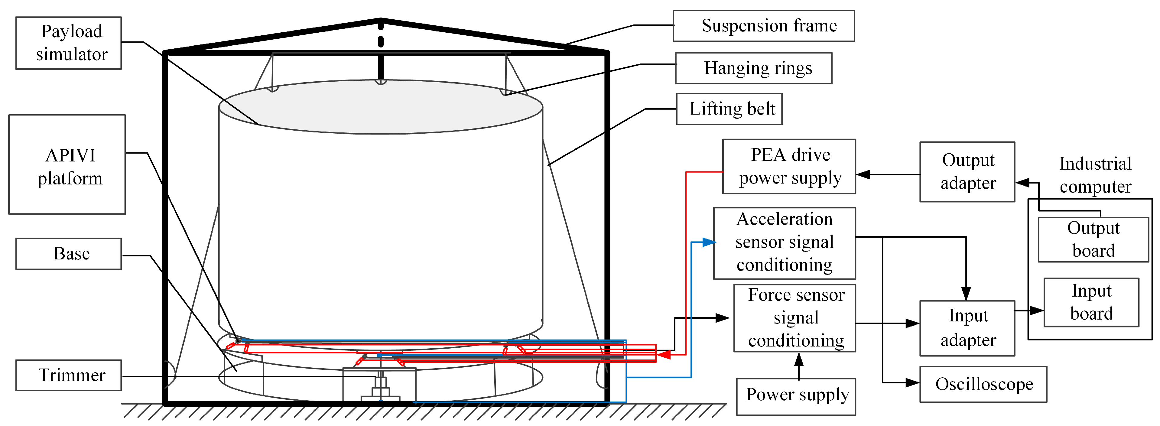
2. Mechanical Design of the APIVI Platform

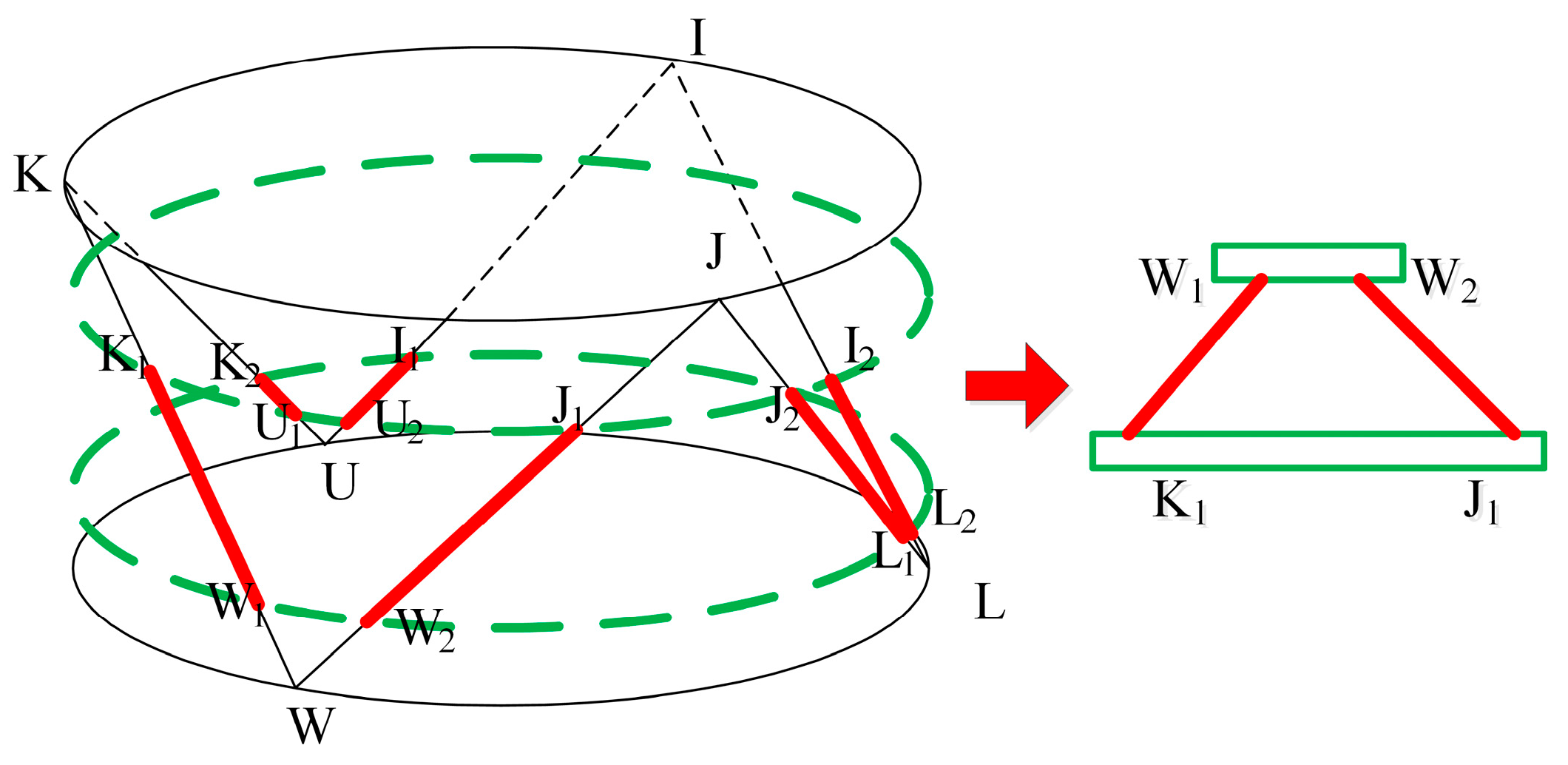
In this paper, an orthogonal vibration isolation module is designed, in which two support rods are perpendicular to each other and converged at a point. According to the Cubic Stewart idea, the two support rods of the orthogonal vibration isolation module are linearly independent. So, each rod can be controlled separately by the same control method, which simplifies the control system and improves the reliability. The design process of the orthogonal vibration isolation module is shown in Figure 1. Limited by the space size, the supporting rods cannot intersect, but their extension lines are orthogonal to each other, so they are still linearly independent in the direction of the bar rectangle.
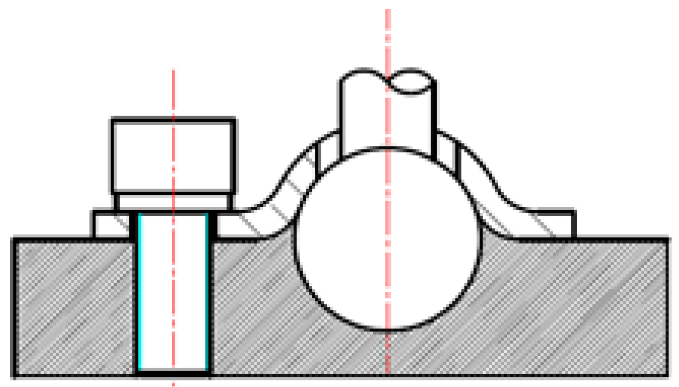
The active and passive integrated actuator is connected with the connecting plate of the upper and lower platform through the non-clearance ball hinge, which is composed of a ball joint press plate, a ball joint ball head, a fastening screw, and a transfer plate with a ball groove, as shown in Figure 2. The ball head is fixed in the spherical groove of the adapter plate through contact extrusion of the screw and the ball hinge pressing plate, so that the output force of the master passive integrated actuator rod is mainly the driving force provided by the piezoelectric ceramics in the long direction of the rod, and the micro-rotation around the three directions can also be generated because the micro-axial deformation caused by the active control of the master and passive integrated actuator rod can cause an attitude change in the vibration isolation platform.
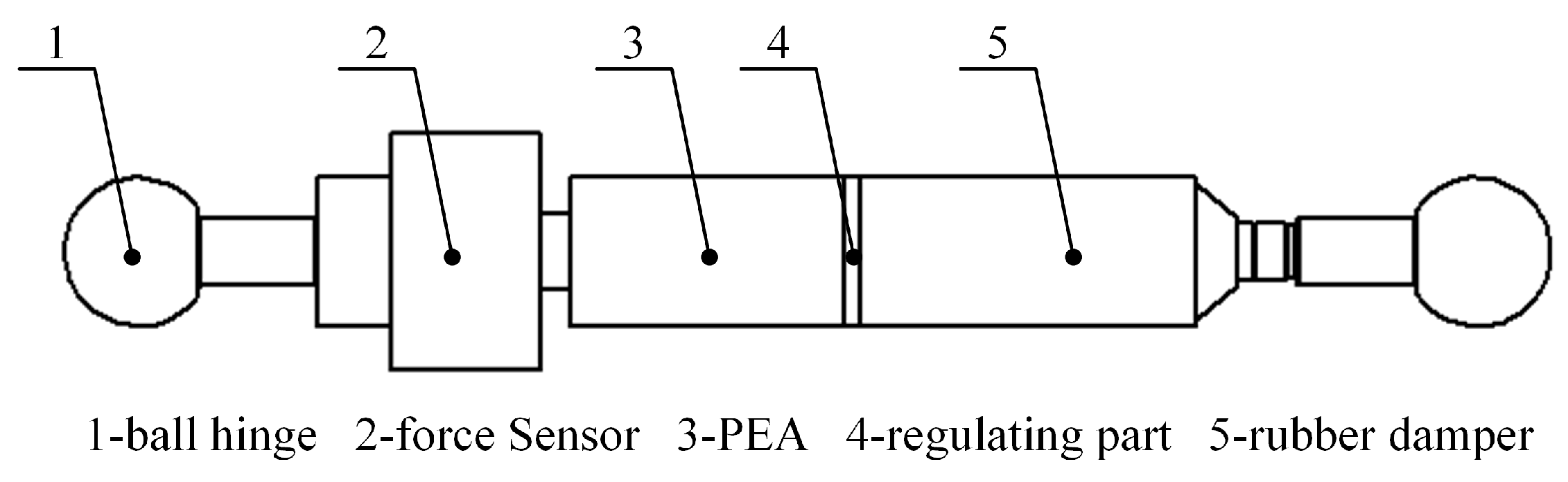
Based on the structure of non-clearance ball joint, the active and passive integrated actuator and ball joint head are designed as a whole supporting rod, as shown in Figure 3. Two high-precision ball joint heads are at each end of each rod, and a moving pair is in the middle. In order to ensure that the balance position of the upper platform can be adjusted to adapt to different loads, the support rod integrated force sensor is used to monitor the axial force of the support rod in real time, and also provides control variables for the subsequent control strategy.
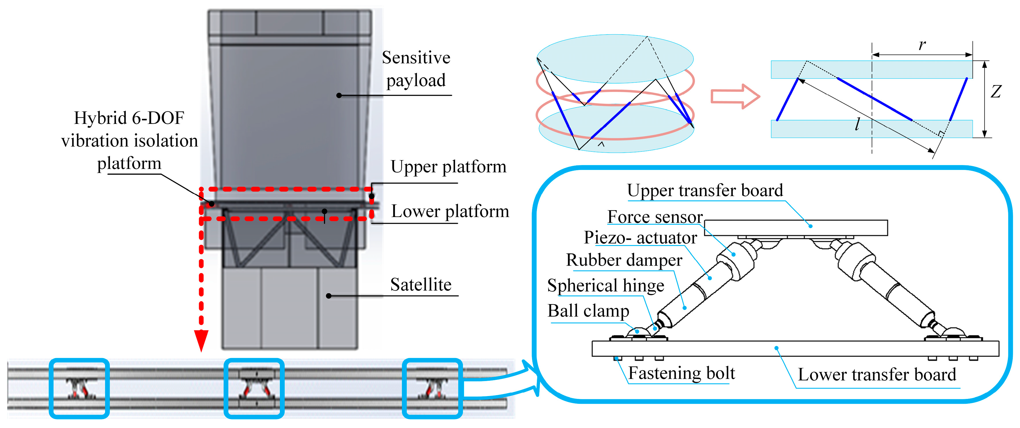
The APIVI platform structure adopts modularization design, which is composed of three orthogonal vibration isolation modules, as shown in Figure 4. In order to achieve different suppression requirements and adapt to various payloads, the modules can be combined according to different quantities and layouts to match various multi-dimensional vibration isolation platforms.

3. Control of the APIVI Platform

3.1. Parameter Determination for H Control of APIVI Platform

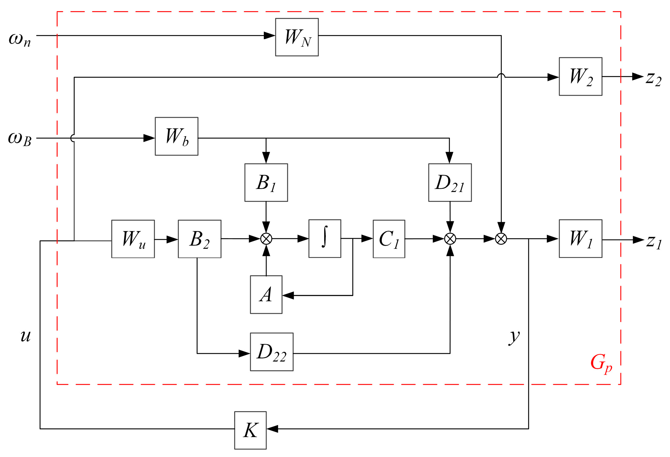
Aiming at the problem of vibration control in the APIVI platform, a controller was designed to stabilize the closed-loop control system and minimize the transfer function H∞ of from external disturbances to sensitive payloads. The acceleration response of the moving platform and the active control force provided by the integrated active and passive actuator based on piezoelectric ceramics are defined as the output signals of the entire closed-loop control system, the measured quantity is the response of the moving platform, and the disturbance (excitation signal) received by the lower platform is the external input signal. The generalized coordinates of the six-dimensional orthogonal vibration isolation platform are defined as q = x , y , z , α , β , γ T = x A , where xA is state variable. The state vector of the system is X = x A T x ˙ A T   , the input vector is ω = ω B T   ω n T   ,   ω B is disturbed signal, and   ω n is the noise signal of the sensor. The control vector is   u = F a , Fa is active actuator dynamic output force. Measured output vector is   y = y ~ + ω n ,   y ~ is represents the acceleration signal on the platform without considering the influence of sensor noise. z = z 1 z 2 T indicates the output signal of the control system, z1 is the acceleration response of the moving platform, and z2 is the control force provided by an integrated active and passive actuator.
The state space expression of the APIVI platform can be derived as [30]
X ˙ = A X + B 1 ω + B 1 u ,
where A = 0 6 × 6 E 6 × 6 M q 1 K q M q 1 C q ,   B 1 = 0 6 × 6 0 6 × 6 M q 1 E 6 × 6 0 6 × 6 ,   B 2 = 0 6 × 6 M q 1 J .
Assuming 0 6 × 6 E 6 × 6 = H , the measured quantity can be derived as
y = 0 6 × 6 E 6 × 6 x ˙ + 0 6 × 6 E 6 × 6 ω B ω n = H A x + H B 1 + H ω + H B 2 u = C 2 x + D 21 ω + D 21 u ,
where C 2 = M q 1 K q M q 1 C q , D 21 = M q 1 E 6 × 6 E 6 × 6 , D 22 = M q 1 J . State space expression of APIVI platform can be derived as
x ˙ = A x + B 1 ω + B 2 u z = C 1 x + D 11 ω + D 12 u y = C 2 x + D 21 ω + D 22 u ,
Laplace transform Equation (1),
s X s = A X s + B 1 W s + B 2 U s ,
and assuming Q = s I A 1 ,
X = Q B 1 W + Q B 2 U ,
substitute Equation (5) into the Laplace transform of Equation (2)
Y = H A Q B 1 + H B 1 + H W + H A Q B 2 + H B 2 U       = H A Q B 1 + H B 1 W + H A Q B 2 + H B 2 U + W U       = H A Q B 1 + H B 1 0 E W B + H A Q B 1 + H B 1 H T W n + H A Q B 2 + H B 2 U + H W       = G 1 W B + G 2 U + W n ,
where H A Q B 1 + H B 1 H T = 0 , G 1 = H A Q B 1 + H B 1 0 E + E , G 2 = H A Q B 2 + H B 2 .
Substitute Z = Z 1 Z 2 T = Y U T into Equation (6). By adding weight functions W1, W2, WN, Wb, Wu to Z1, Z2, WN, WB, and U, generalized matrix can be obtained with simplification.
G p = W 1 G 1 W b W N W 1 G 2 W u 0 0 W 2 G 1 W b W N G 2 W u ,
The relationship between input and output of the closed-loop control system of APIVI platform can be obtained as follows
z 1 z 2 y = G p ω B ω n u ,
The standard H robust control model of the APIVI platform is obtained, and the design block diagram of the model is shown in Figure 5.
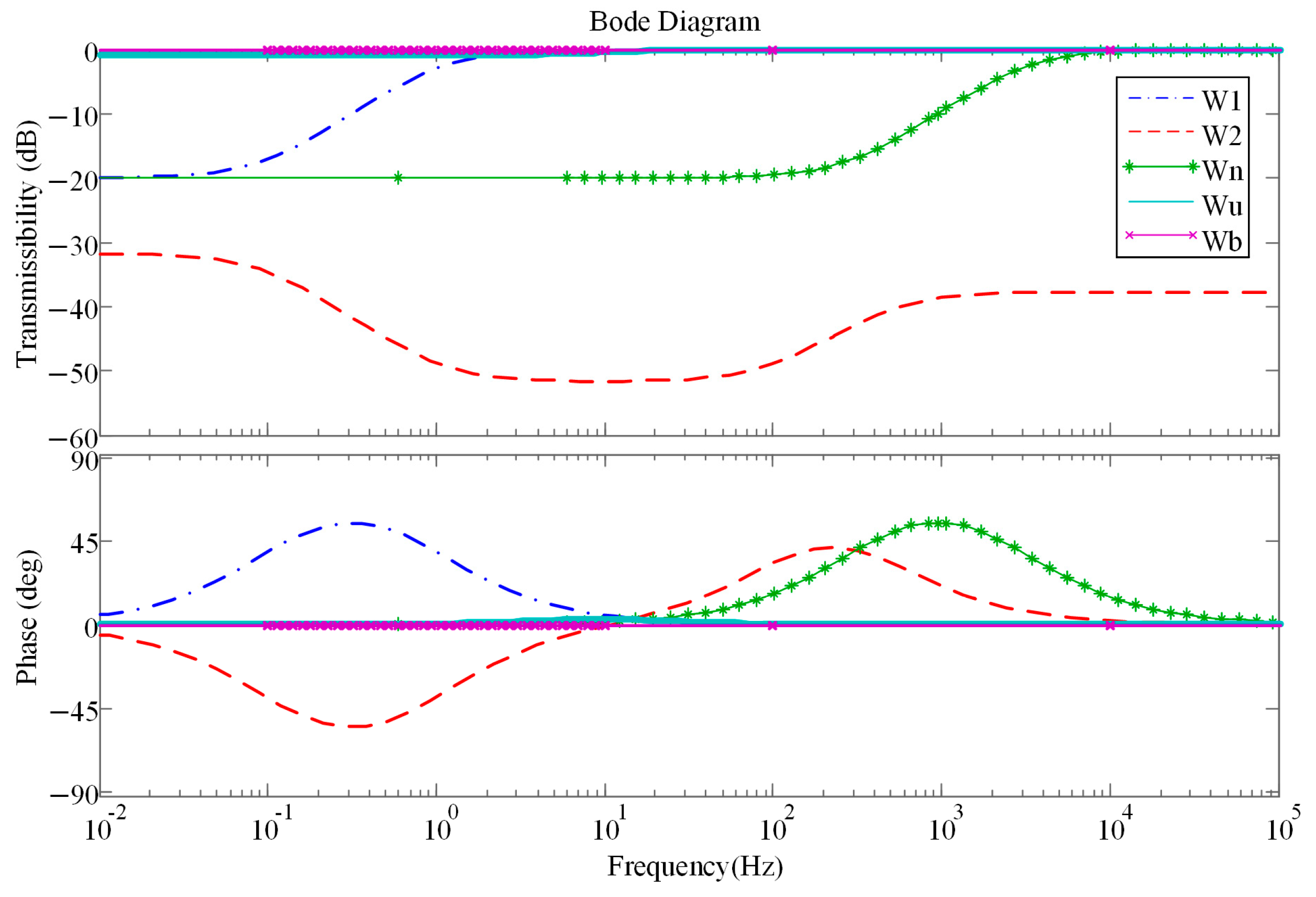
In order to prevent the high order of the designed controller from increasing the calculation and implementation difficulty, the weighted function value with low order should be selected. In the frequency range of 10–200 Hz, active control is required to suppress the disturbance and reduce the impact on the sensitive payload. The weighted function value W1 describes the acceleration response of the moving platform and the relative weight between the control target and the input variable. Therefore, W1 is designed to be as large as possible within the desired control effective frequency domain to improve the control performance, and as small as possible outside the desired control effective frequency domain. The weighted function value W2 describes the active control force and the relative weight between the control target and the input variable. W2 is designed to be as small as possible in the desired control effective frequency domain to obtain a larger active control force, and as large as possible outside the desired control effective frequency domain to reduce the output of the actuator. Therefore, in order to protect the piezoelectric ceramics, it is necessary to make W2 greater than −77.3 dB to prevent excessive control. Wn describes a high-pass filter to allow high-frequency noise signals to enter the system. Therefore, the function with smaller weight at low frequency and larger weight at high frequency is selected. The excitation weighted function value Wb is set to I6×6. In order to ensure that the controller can have linear output characteristics in the desired effective frequency range, the design Wu I6×6.
According to the requirements of the above weighted function value selection, the value of the weighted function is determined as
W 1 = s + 0.1 s + 100 s + 1 s + 10 I 6 × 6 ,   W 2 = 0.015 s 2 + 2.313 s + 1.5 s 2 + 100   s + 1000 I 6 × 6 ,   W n = 0.2 s + 200 s + 20,000 I 6 × 6 ,     W b = I 6 × 6 ,   W u = s + 8 s + 9 I 6 × 6
Bode diagram of the transfer function value of the weighted function of H controller of the APIVI platform is shown in Figure 6.
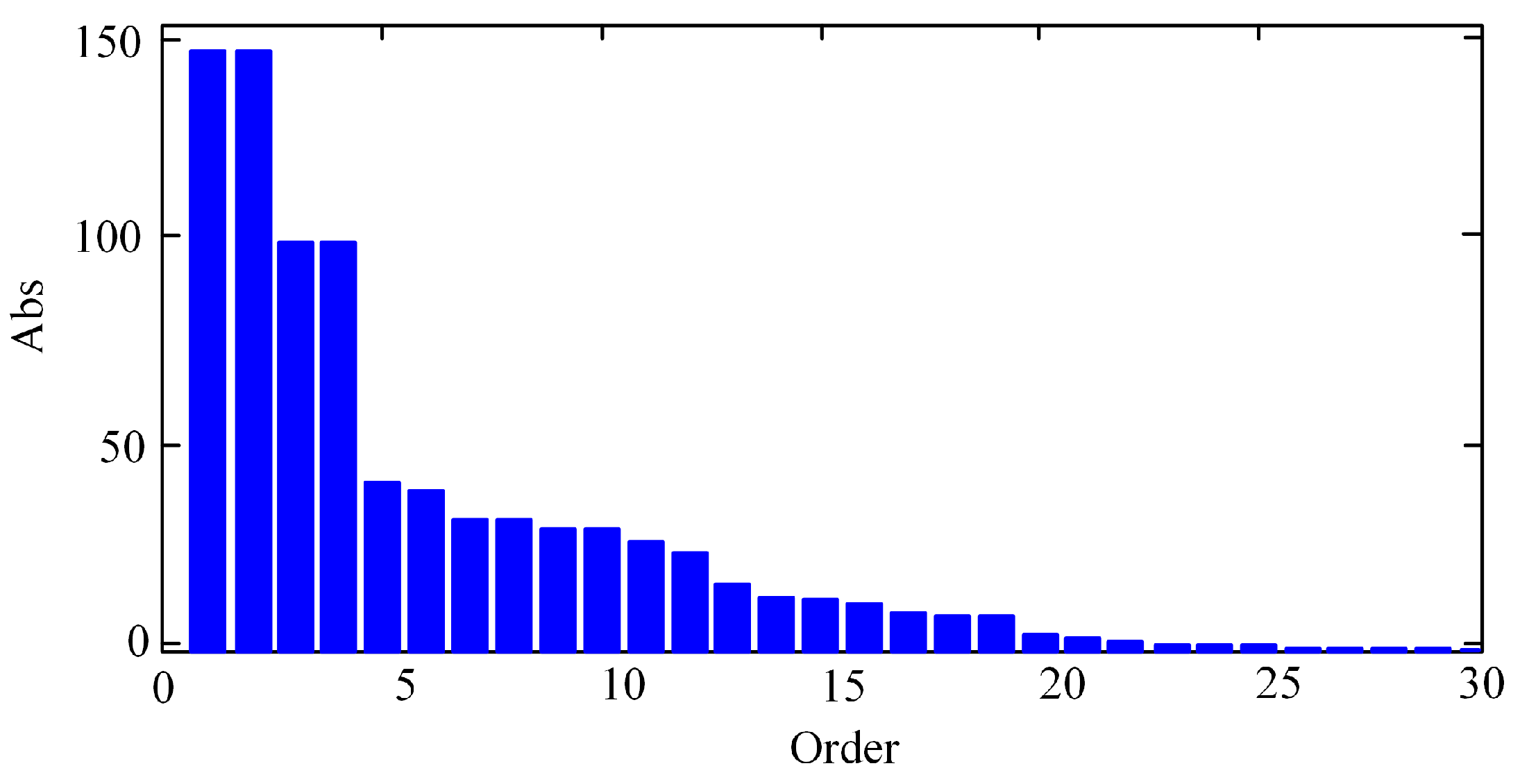
The weighted function value is substituted into Equation (7), and the minimum value γ of G P is calculated. With iteration, the final γ = 0.9488 is calculated. For a complex system with high dimensions, the high order controller is difficult to analyze and implement in engineering. Order reduction in the higher-order model is the most effective way to solve problem. Therefore, Hankel norm singular value reduction method was adopted to reduce the order of the controller and screen out a transfer function. The H norm of the model is close to the original controller, and the H norm of the model reduction error is minimized. Hankel singular value distribution of the H∞ controller is obtained, as shown in Figure 7. By eliminating the smaller Hankel singular values, the controller order is 10.

3.2. Robust Control of APIVI Platform with Uncertain Parameters

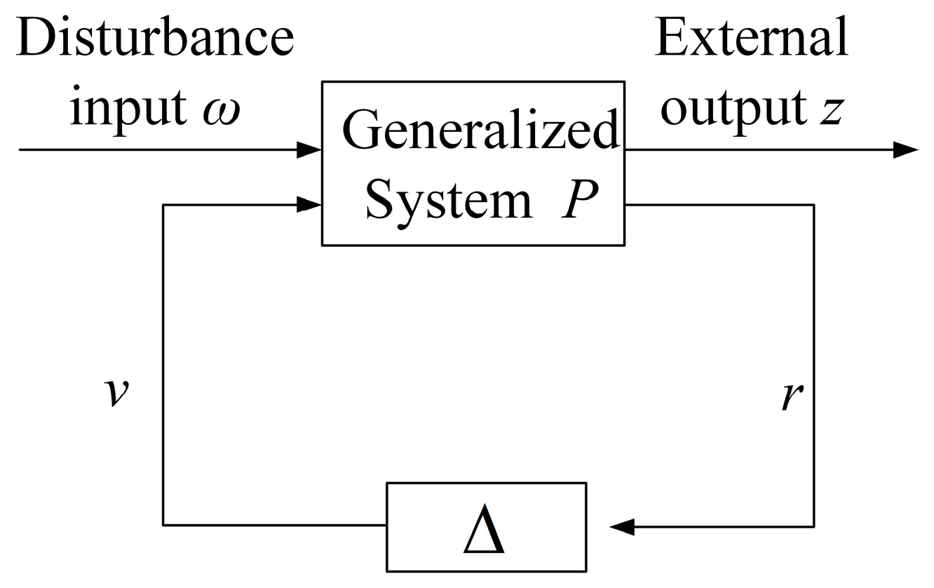
In order to suppress the micro-vibration of space-sensitive payloads, it is necessary to consider the uncertain factors, such as the machining precision of payloads or the deviation between the design value and the actual value of stiffness and damping caused by aging components. A controller was designed to make the system work normally under the condition of parameter perturbation and achieve the control goal.
Robustness analysis was added to stability analysis by μ synthesis theory, so that the singular value of the system can meet certain requirements even in the worst case. A system with uncertain structure is shown in Figure 8, where P is the generalized system, v is the control input, r is the measurement output, and Δ is the set of partitioned diagonal matrices.
μ is defined as a structural singular value
μ Δ = 1 min σ max Δ Δ Δ , det E P Δ = 0 ,
Assuming the stiffness and damping of the APIVI platform have 5% parameter perturbations, the system control model with parameter perturbations is established. The state space Equation (3) can be rewritten as
x ˙ = A x + B λ t = C x + D λ ,
where B = B 1 B 2 , C = C 1 C 2 , t = z y , λ = ω u . Parametric perturbations of the spring and damping cause matrix A to change.
Assuming A = A 0 + A , A 0 is a matrix composed of design parameters, and A is a matrix composed of perturbation parameters. A = A k η k + A c η c , where K = K 0 + 0.05 K 0 η k , C = C 0 + 0.05 C 0 η c ,   η k < 1 ,   η c < 1 .
According to matrix A obtained in Equation (1), A k = 0 6 × 6 E 6 × 6 0.1 M q 1 K 0 q 0 6 × 6 , A c = 0 6 × 6 0 6 × 6 0 6 × 6 0.1 M q 1 C 0 q .
Defining S = A B C D = S 0 + S K + S C , by using linear fraction transformation to decompose S, the structural parameter uncertainty problem can be transformed into matrix uncertainty.
S k = A k 0 12 × 18 0 18 × 12 0 18 × 18 = E k F k G k H k ,
where E k = 0 6 × 6 0.1 M q 1 K 0 q , F k = E 6 × 6 0 6 × 6 0 6 × 6 ,   G k = 0 6 × 6 E 6 × 6 , H k = E 6 × 6 0 6 × 6 0 6 × 6 T .
S c = A c 0 12 × 18 0 18 × 12 0 18 × 18 = E c F c G c H c ,
where E c = 0 6 × 6 0.1 M q 1 K 0 q ,   F k = 0 6 × 6 0 6 × 6 0 6 × 6 , G c = E 6 × 6 0 6 × 6 ,   H c = 0 6 × 6 0 6 × 6 0 6 × 6 T .
Then, the parametric uncertainty model can be expressed as
x ˙ t r 1 r 2 = A 0 B E k E c C D F k F c G k H k 0 6 × 6 0 6 × 6 G c H c 0 6 × 6 0 6 × 6 x λ v 1 v 2 ,
The parametric uncertainty model describes the transfer relationship between input and output in the form of state space.
v 1 v 2 = Δ P r 1 r 2 ,
Combining state space Equation (3) of the six-dimensional orthogonal vibration isolation platform system and the inputting to output relationship (8) of the closed-loop control system of the six-dimensional orthogonal vibration isolation platform obtained above, the following can be obtained:
x ˙ r 1 r 2 z y = A 0 E k E c B 1 B 2 G k 0 6 × 6 0 6 × 6 H k H c G c 0 6 × 6 0 6 × 6 H k H c C 1 0 6 × 6 0 6 × 6 D 11 D 12 C 2 0 6 × 6 0 6 × 6 D 21 D 22 x v 1 v 2 ω u ,
The transfer matrix from input to output is obtained by transforming the transfer function in state space, which is the generalized control object
r z y = G v ω u = G 11 G 12 G 21 G 22 v ω u ,
The transfer function of the closed-loop control system can be obtained by combining the obtained generalized control object G with the controller Kc.
P = G 11 + G 12 K C I G 22 K C 1 G 21 ,

3.3. Simulation of APIVI Platform

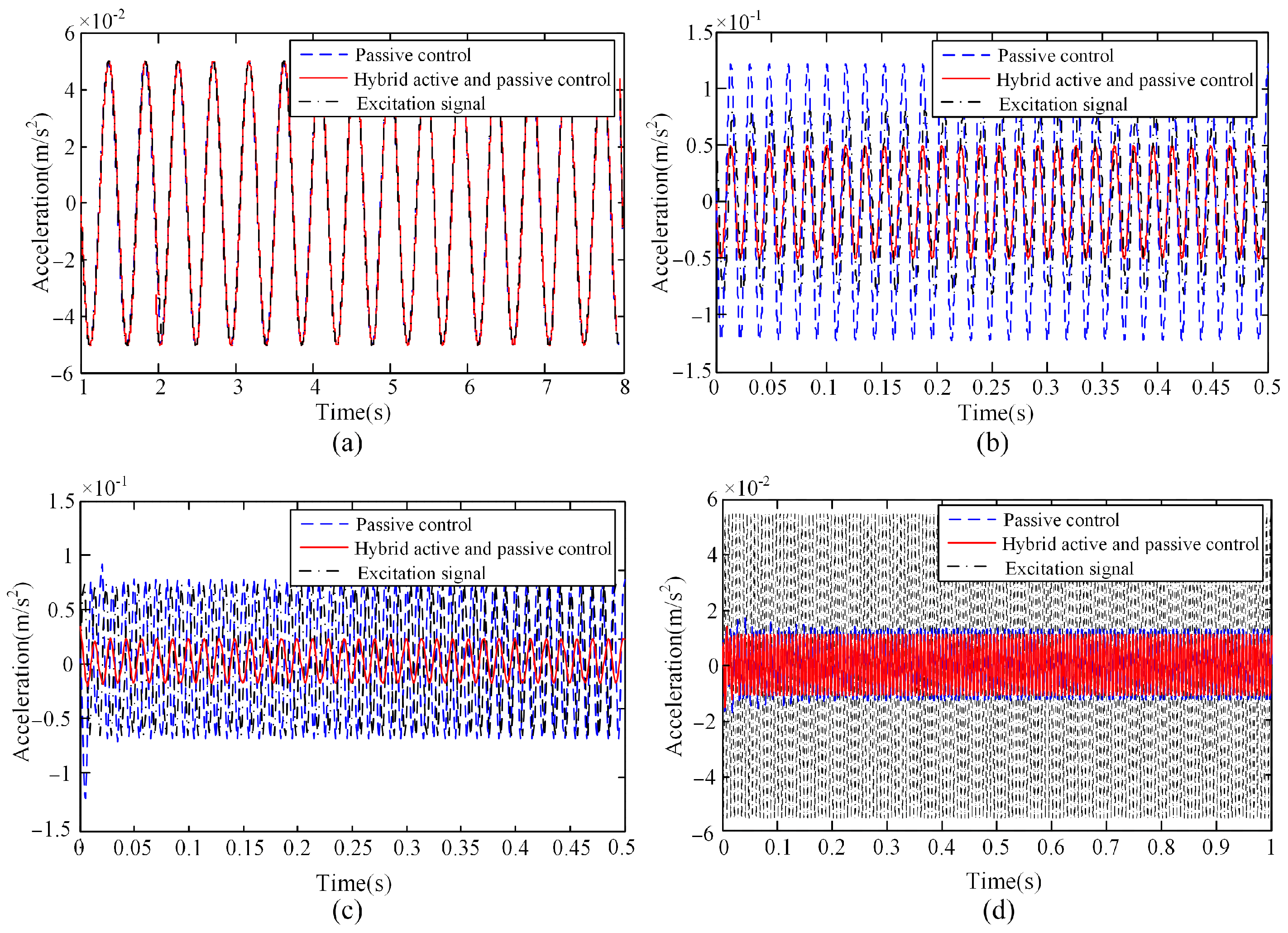
In order to verify the effectiveness of the controller of APIVI platform, single-frequency sinusoidal excitation signals with frequencies of 5 Hz, 40 Hz, 80 Hz, and 150 Hz were applied to the lower platforms of APIVI platform. The acceleration response at the upper platform centroid is shown in Figure 9. The simulation results show that when the excitation signal frequency is 5 Hz, the APIVI platform demonstrates no isolating effect no matter whether the controller is on or off. When the excitation signal frequency is 40 Hz, passive vibration isolation amplifies the excitation signal. With active control, the system can attenuate the excitation signal, indicating that 40 Hz has entered the effective vibration isolation band of active control. When the frequency of the excitation signal is 80 Hz, the passive control demonstrates no isolating effect. With active control, the effective attenuation of the excitation signal by the active and passive integrated control can reach 60%. When the frequency of the excitation signal is 150 Hz, there is little difference between the passive control and the active and passive integrated control, the vibration attenuation reaches 80%, and the passive control in the high-frequency region plays a major role. Passive isolation fails to suppress low-frequency vibrations. In the frequency band of 2 ω n / 2 , 2 ω n , the vibrations are amplified. There is a conflict between resonance suppression and high-frequency suppression. The passive vibration isolation performs well in the high-frequency region. The simulation results verify the superiority of the proposed APIVI platform in vibration isolation performance, the active control of the isolation action, and the high-frequency vibration isolation performance of the passive structure itself is excellent, which solves the problem where the effective frequency band of active control is limited by the bandwidth and power of the piezoelectric ceramics.
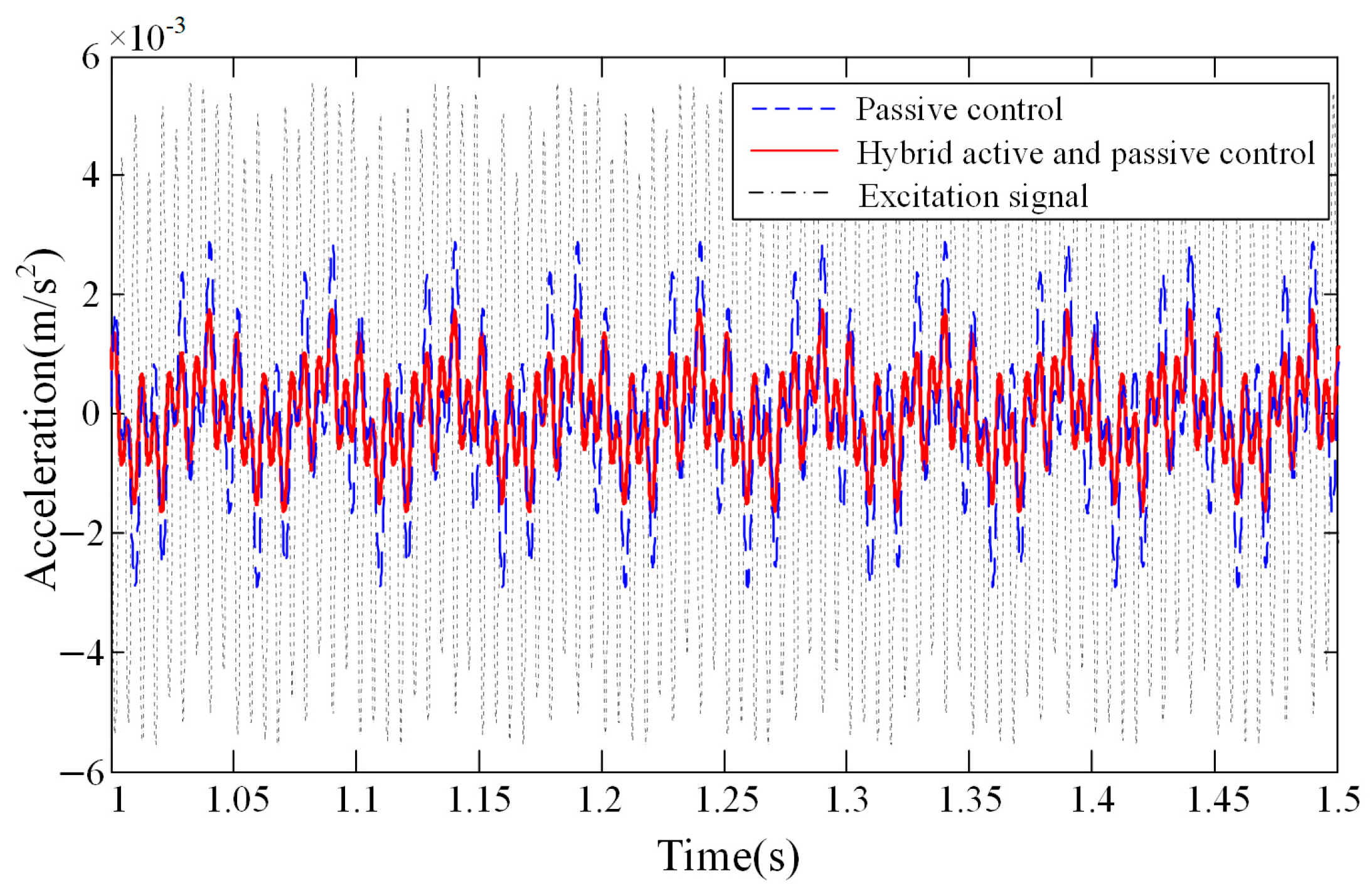
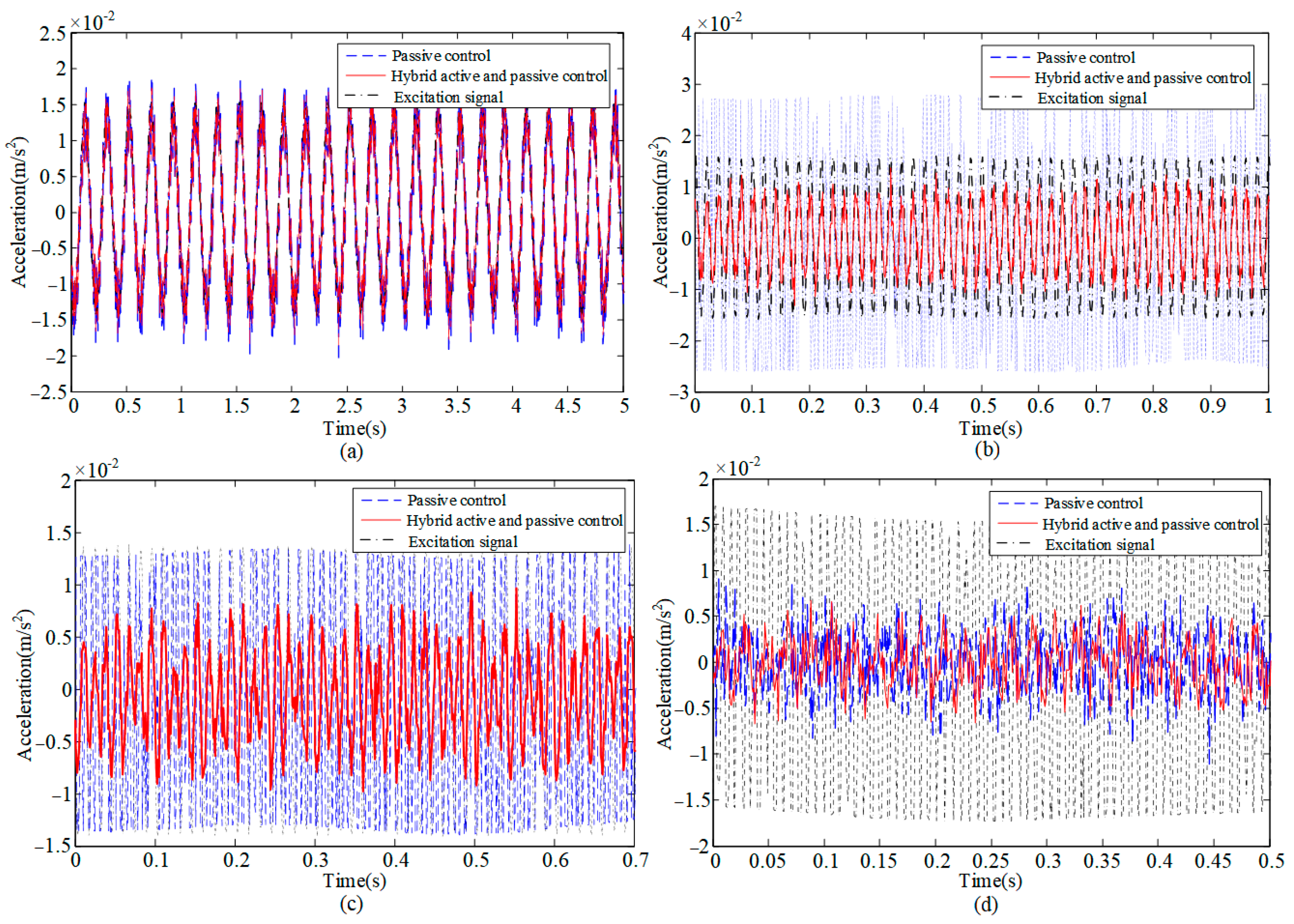
A composite single-frequency sinusoidal excitation signal composed of 20 Hz, 80 Hz, and 180 Hz was applied to the lower platform of the APIVI platform, and the acceleration response at the centeroid of upper platform was obtained, as shown in Figure 10. APIVI platform can effectively reduce vibration transmission.
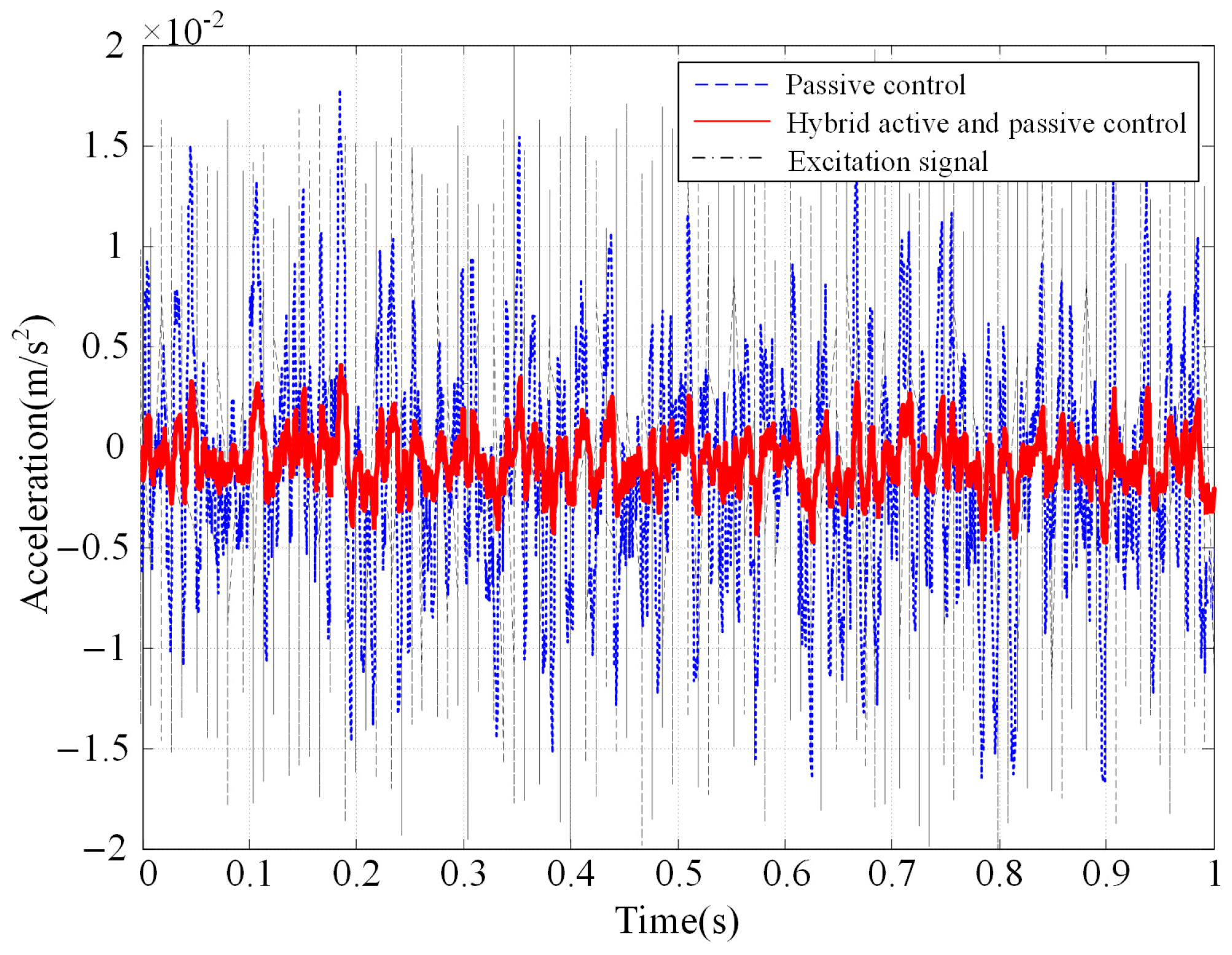
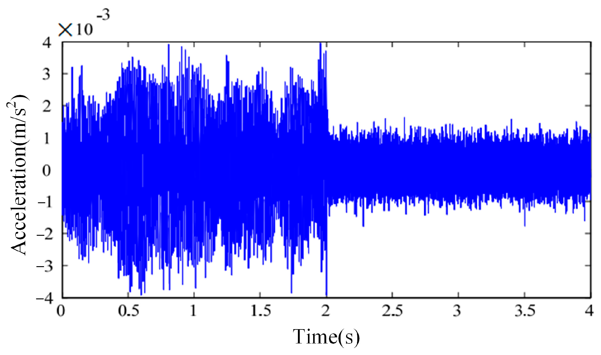
A random excitation signal was applied to the lower platform of the APIVI platform. The acceleration response at the centeroid of upper platform is shown in Figure 11. With the hybrid active and passive control, the APIVI platform under the integrated active–passive control can significantly and effectively attenuate the random disturbances, with the vibration attenuation reaching more than 80%.
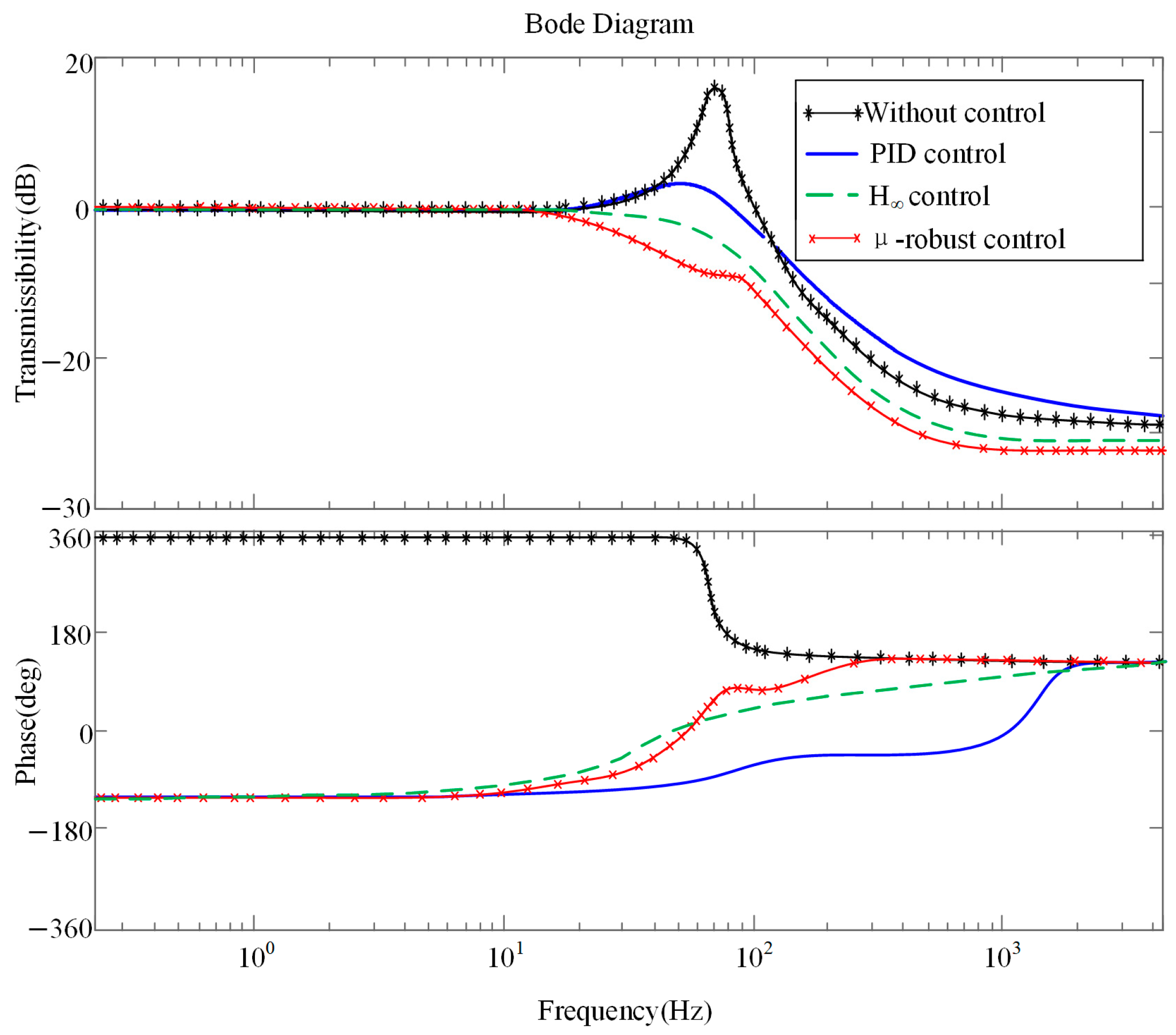
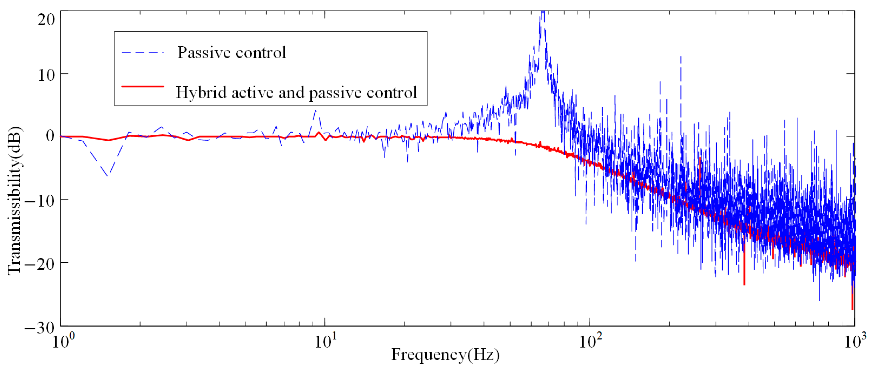
The vertical sweep signal was applied to the lower platform of APIVI platform for comparing the transmission characteristics of the system with different control strategies, as shown in Figure 12. When the controller is off, APIVI platform presents the transmission characteristics of a passive vibration isolation system, and the first-order resonance peak appears at 73 Hz. The effective isolation frequency band of passive vibration isolation ranges above 105 Hz. PID controller with appropriate feedback coefficient can attenuate the first-order resonance peak of the system, but the high-frequency vibration isolation effect is slightly worse. The vibration isolation performance of H robust controller is obviously better at resonant peak or high-frequency band. μ synthesis-based robust controller performs the best vibration isolation effect in middle, resonant, and frequency.

4. Experimental Study

4.1. Set Up of Experimental System

Due to the large weight and low natural frequency of the space payload, auxiliary suspension measures must be taken for the space payload, which can offset the excessive deformation caused by gravity and reduce the load of the actuator and simulate the microgravity state of the space payload in orbit. The suspension of the payload in the ground experiment can also make the balance position of the APIVI platform similar to that in orbit. The experimental system of the space payload APIVI platform is mainly composed of a payload simulator, suspension device, lower platform, vibration isolation module composed of active and passive integrated actuator, piezoelectric ceramic driving power supply, sensor, signal conditioner, multi-function data acquisition card, industrial computer, power amplifier, excitation equipment, etc. The experimental scheme design is shown in Figure 13.
The program block diagram of the APIVI platform control system is shown in Figure 14. Because of the bandwidth and power limitations of the piezoelectric ceramics, the output control voltage signal should be limited to prevent the excessive voltage output from breaking down and damaging the piezoelectric ceramics.

4.2. Analysis of Experimental Results

In order to verify the theoretical analysis and simulation results, the vertical single-frequency sinusoidal excitation signal was applied to the APIVI platform. The changes in the acceleration response of the six-dimensional orthogonal vibration isolation platform before and after the active control under the sinusoidal excitation of 5 Hz, 40 Hz, 80 Hz, and 150 Hz were tested. The experimental results are shown in Figure 15. The experimental results are similar to the simulation results, which can verify the validity of the simulation analysis. In the ultra-low-frequency region, the controller shows no attenuation effect, but introduces electromagnetic interference and causes burrs. In the low-frequency band, which does not exceed the first natural frequency, it is obvious that the excitation signal is amplified with passive control, and the APIVI platform can attenuate the excitation signal by 33% with hybrid active and passive control. Near the first-order natural frequency of 80 Hz, the experimental results are slightly different from the simulation results. The experimental results show that the excitation signal is weakly attenuated with passive control, and the APIVI platform shows a large attenuation effect on the excitation signal with hybrid active and passive control. The first-order natural frequency of the actual system is lower than the simulation result. In the high-frequency region, similar to the simulation results, the vibration attenuation reached 77%, which was slightly lower than simulation, because the actual driving force could not reach the optimal active control force calculated by the controller.
In order to test the robustness of the control algorithm, a random excitation signal was applied to the lower platform of the APIVI platform. The experimental test result is shown in Figure 16. The control system was turned on 2 s after the start of data collection. The acceleration response of the load platform was significantly reduced. Compared with the situation without control, the peak value of the response of the load platform is attenuated by 60%.
Vertical sweep frequency signals were applied to the lower platform to compare the system transmission characteristics with and without active control, as shown in Figure 17. The first-order resonance peak appears at 68 Hz. The excitation signal can be attenuated only when the excitation frequency exceeds 80 Hz, and the attenuation effect is better with the increase in the excitation frequency. The hybrid active and passive control effect of the robust control strategy is better than passive control in low- and high-frequency bands, which can completely reduce the first-order resonance peak of the system with a maximum attenuation 18 dB. The effective attenuation frequency range is above 18 Hz, which does not reach the simulation results. That may be due to processing and assembly errors or idealized processing of the model during simulation. The transmission characteristic experiment proves that APIVI platform with robust control strategy can effectively attenuate the vibration at the middle- and low-frequency band and the resonance peak by using active control, and attenuate the high-frequency vibration by using its good passive structure and high-frequency band vibration isolation performance.

5. Conclusions

In this paper, a novel six-degree-of-freedom (6-DOF) hybrid active–passive vibration isolation platform was proposed and developed. The APIVI platform features a three-dimensional orthogonal decoupled configuration, with each axis independently integrated with piezoelectric active actuator units and rubber passive isolation modules. A nonlinear dynamic model incorporating electromechanical coupling effects is established using a modified Lagrangian formulation, effectively characterizing the frequency-dependent characteristics of the hybrid isolation system. To address the parameter perturbations caused by manufacturing tolerances and component aging in practical engineering applications, a structured uncertainty model is constructed. An innovative μ-synthesis robust control methodology is employed to design an H controller, achieving broadband vibration suppression while ensuring system stability. Experimental investigations under simulated on-orbit microgravity conditions demonstrate that the APIVI platform exhibits outstanding vibration isolation performance above 18 Hz. Compared with purely passive isolation systems, the active control strategy successfully eliminates the first-order resonance peak with an attenuation of 18 dB.

Author Contributions

Methodology, Y.Z.; simulated analysis, T.Z.; validation, Z.Z. and Y.Z.; resources, W.F.; writing—original draft preparation, Y.Z.; writing—review and editing, Y.Z. and W.F. All authors have read and agreed to the published version of the manuscript.

Funding

This research was funded by the Suzhou Basic Scientific Research Project, grant number SSD2024013.

Data Availability Statement

The original contributions presented in the study are included in the article, further inquiries can be directed to the corresponding author.

Conflicts of Interest

The authors declare no conflict of interest.

Abbreviations

The following abbreviations are used in this manuscript:
APIVIActive–passive integrated 6-dimensional orthogonal vibration isolation
PIDProportional integral derivative
MAIMulti-target active vibration isolation platform
MRMagnetorheological

References

  1. Bronowicki, A.J. Vibration Isolator for Large Space Telescopes. J. Spacecr. Rocket. 2012, 43, 45–53. [Google Scholar] [CrossRef]
  2. Cobb, R.G.; Sullivan, J.M.; Das, A.; Davis, L.P.; Hyde, T.T.; Davis, T.; Rahman, Z.H.; Spanos, J.T. Vibration Isolation and Suppression System for Precision Payloads in Space. Smart Mater. Struct. 1999, 8, 798. [Google Scholar] [CrossRef]
  3. Esmaeili, A.; Sousa, J.M.M. Flow-Driven Piezoelectric Energy Harvester on a Full-Span Wing for Micro-aerial-vehicle (MAV) Application. Arab. J. Sci. Eng. 2020, 45, 5713–5728. [Google Scholar] [CrossRef]
  4. Xu, B.; Shi, Z. An overview on flight dynamics and control approaches for hypersonic vehicles. Sci. China Inf. Sci. 2015, 58, 1–19. [Google Scholar] [CrossRef]
  5. Cole, T.J.; Bassler, J.; Cooper, S.; Stephens, V.; Ponnusamy, D.; Briere, M.; Betenbaugh, T. The challenges of designing a lightweight spacecraft structure for landing on the lunar surface. Acta Astronaut. 2012, 71, 83–91. [Google Scholar] [CrossRef]
  6. Li, L.; Gong, X.; Zhu, F.; Yu, Y.; Zhao, Q.; Zhang, L.; Zhang, Y.; Wu, Y.; Wang, L. Simulation and Experiment of Effect of Microvibration on pointing measurement of high-performance spacecraft. J. Deep. Space Explor. 2023, 10, 277–282. [Google Scholar] [CrossRef]
  7. Du, L.F.; Ji, L.W.; Luo, Y.J.; Shao, S.B.; Xu, M.L. Simulation and Experiment of an Active-Passive Isolator for Micro-Vibration Control of Spacecraft. In Proceedings of the 2020 15th Symposium on Piezoelectrcity, Acoustic Waves and Device Applications (SPAWDA), Zhengzhou, China, 16–19 April 2021. [Google Scholar] [CrossRef]
  8. Fang, J.; Xu, X.; Xie, J. Active vibration control of rotor imbalance in active magnetic bearing systems. J. Vib. Control. 2013, 21, 684–700. [Google Scholar] [CrossRef]
  9. Wei, Z.; Li, D.; Luo, Q.; Jiang, J. Modeling and analysis of a flywheel microvibration isolation system for spacecrafts. Adv. Space Res. 2015, 55, 761–777. [Google Scholar] [CrossRef]
  10. Carrella, A. Passive Vibration Isolators with High Static and Low Dynamic Stiffness. Ph.D. Thesis, University of Southampton, Southampton, UK, 2008. [Google Scholar]
  11. Wu, Z.; Jing, X.; Sun, B.; Li, F. A 6DOF passive vibration isolator using X-shape supporting structures. J. Sound Vib. 2016, 380, 90–111. [Google Scholar] [CrossRef]
  12. Li, Q.; Wang, C.; Huang, X.; Zhang, Z. Analysis and Experiment of Micro-Vibration Active Control based on Stewart Platform. Noise Vib. Control. 2016, 36, 5. [Google Scholar] [CrossRef]
  13. Chi, W.; Ma, H.; Wang, C.; Zhao, T. Research on Control of Stewart Platform Integrating Small Attitude Maneuver and Vibration Isolation for High-Precision Payloads on Spacecraft. Aerospace 2021, 8, 333. [Google Scholar] [CrossRef]
  14. Environments Workshop; The Aerospace Corporation: El Segundo, CA, USA, 2003; pp. 1–29.
  15. Zhang, Q.; Li, B.; Zhao, G.; Miao, H.; Wang, C.; Liu, N.; Liu, J. Design and optimization of self-sensing voice coil actuator for spacecraft micro-vibration isolation. Acta Astronaut. 2025, 229, 901–917. [Google Scholar] [CrossRef]
  16. Hanieh, A. Active Isolation and Damping of Vibrations via Stewart Platform. Ph.D. Thesis, Universite Libre de Bruxelles, Brussels, Belgium, 2003; pp. 8–13. [Google Scholar]
  17. Preumont, A.; Horodinca, M.; Romanescu, I. A Six-dimension Single Stage Active Vibration Isolator Based on Stewart Platform. J. Sound Vib. 2007, 300, 644–661. [Google Scholar] [CrossRef]
  18. Hanieh, A.A.; Preumont, A. Multi-axis vibration isolation using different active techniques of frequency reduction. J. Vib. Control. 2011, 17, 759–768. [Google Scholar] [CrossRef]
  19. Shuai, C.; Ma, J.; Rustighi, E. The Development of an Intelligent Hybrid ActivePassive Vibration Isolator. J. Phys. Conf. Ser. 2016, 744, 012160. [Google Scholar] [CrossRef]
  20. Zhang, F.; Shao, S.; Tian, Z.; Xu, M.; Xie, S. Active-Passive Hybrid Vibration Isolation with Magnetic Negative Stiffness Isolator Based on Maxwell Normal Stress. Mech. Syst. Signal Process. 2019, 123, 244–263. [Google Scholar] [CrossRef]
  21. Nguyen, V.-Q.; Choi, S.-M.; Choi, S.-B.; Moon, S.-J. Sliding Mode Control of a Vibrating System Using a Hybrid Active Mount. Proc. Inst. Mech. Eng. Part C J. Mech. Eng. Sci. 2009, 223, 1327–1337. [Google Scholar] [CrossRef]
  22. Li, F.; Yuan, S.; Qian, F.; Wu, Z.; Pu, H.; Wang, M.; Ding, J.; Sun, Y. Adaptive Deterministic Vibration Control of a Piezo-Actuated Active–Passive Isolation Structure. Appl. Sci. 2021, 11, 3338. [Google Scholar] [CrossRef]
  23. Han, Y.-M.; Choi, S.-M.; Choi, S.-B.; Lee, H.-G. Design and Control of a Hybrid Mount Featuring a Magnetorheological Fluid and Apiezostack. Smart Mater. Struct. 2011, 20, 075019. [Google Scholar] [CrossRef]
  24. Zhang, B.; Jin, K.; Kou, Y.; Zheng, X. The Model of Active Vibration Control Based on Giant Magnetostrictive Materials. Smart Mater. Struct. 2019, 28, 085028. [Google Scholar] [CrossRef]
  25. He, T.; Wu, Z. Multirate iterative learning disturbance observer with robustness to frequency deviation for high precision attitude stabilization of flexible spacecraft subject to complex disturbances. Aerosp. Sci. Technol. 2020, 96, 105583. [Google Scholar] [CrossRef]
  26. Qian, Y.; Xie, Y.; Jia, J.; Zhang, L. Development of Active Microvibration Isolation System for Precision Space Payload. Appl. Sci. 2022, 12, 4548. [Google Scholar] [CrossRef]
  27. Guo, Q.; Zhou, J.; Li, L.; Xu, M.; Tang, G. Design and Experimental Study of a Hybrid Micro-Vibration Isolation System Based on a Strain Sensor for High-Precision Space Payloads. Sensors 2024, 24, 1649. [Google Scholar] [CrossRef]
  28. Jang, D.-D.; Jung, H.-J.; Shin, Y.-H.; Moon, S.-J.; Moon, Y.-J.; Oh, J. Feasibility Study on a Hybrid Mount System with Air Springs and Piezo-Stack Actuators for Microvibration Control. J. Intell. Mater. Syst. Struct. 2012, 23, 515–526. [Google Scholar] [CrossRef]
  29. Tinoco, V.; Silva, M.F.; Santos, F.N.; Morais, R.; Magalhães, S.A.; Oliveira, P.M. A review of advanced controller methodologies for robotic manipulators. Int. J. Dyn. Control. 2025, 13, 36. [Google Scholar] [CrossRef]
  30. Liu, L.; Wang, B. Multi Objective Robust Active Vibration Control for Flexure Jointed Struts of Stewart Platforms via H∞ and μ-Synthesis. Chin. J. Aeronaut. 2008, 21, 125–133. [Google Scholar] [CrossRef]
Figure 1. The design process of the orthogonal vibration isolation module.
Applsci 15 03437 g001
Figure 2. The schematic diagram of the ball joint without clearance.
Applsci 15 03437 g002
Figure 3. The schematic diagram of the support pole.
Applsci 15 03437 g003
Figure 4. The APIVI platform for sensitive instruments.
Applsci 15 03437 g004
Figure 5. The general frame of the H controller for the six-dimensional orthogonal vibration isolation platform.
Applsci 15 03437 g005
Figure 6. Weighted function’s Bode diagram of H controller for APIVI platform.
Applsci 15 03437 g006
Figure 7. Hankel matrix singular value distribution diagram of H controller for APIVI platform.
Applsci 15 03437 g007
Figure 8. The μ synthesis problems of the uncertain systems.
Applsci 15 03437 g008
Figure 9. The vibration isolation effect of the APIVI platform under vertical sine signal disturbance with different frequencies: (a) 5 Hz; (b) 40 Hz; (c) 80 Hz; and (d) 150 Hz.
Applsci 15 03437 g009
Figure 10. The time domain vibration isolation effect of the six-dimensional orthogonal vibration isolation platform under a vertical composite-frequency sine signal disturbance.
Applsci 15 03437 g010
Figure 11. The time domain vibration isolation effect of the APIVI platform under a random excitation signal.
Applsci 15 03437 g011
Figure 12. Transfer function of APIVI platform with different control strategies under vertical sine signal disturbance.
Applsci 15 03437 g012
Figure 13. Schematic diagram of experimental set-up.
Applsci 15 03437 g013
Figure 14. Mechanical installation schematic diagram of experiment system.
Applsci 15 03437 g014
Figure 15. Acceleration response of APIVI platform with passive control and hybrid control under vertical sine signal disturbance with different frequencies: (a) 5 Hz; (b) 40 Hz; (c) 80 Hz; (d) 150 Hz.
Applsci 15 03437 g015
Figure 16. Acceleration response of APIVI platform with passive control and hybrid control under random excitation signal.
Applsci 15 03437 g016
Figure 17. The transfer function of the APIVI platform with different control strategies under vertical sine signal disturbance.
Applsci 15 03437 g017
Disclaimer/Publisher’s Note: The statements, opinions and data contained in all publications are solely those of the individual author(s) and contributor(s) and not of MDPI and/or the editor(s). MDPI and/or the editor(s) disclaim responsibility for any injury to people or property resulting from any ideas, methods, instructions or products referred to in the content.

