Study on the Design and Construction Methods of Auxiliary Workings for the Deepening of Shaft II in the Borynia Mine
Abstract
1. Introduction
1.1. Overview of Shaft Deepening Methods
- The conventional drill-and-blast method, used in the past for reverse shaft sinking in high quality rock masses without significant waterlogging.
- The deep-hole blasting method, developed to address safety and work efficiency challenges associated with the conventional drill-and-blast method.
- The raise-boring method, which involves excavating the shaft by back-reaming a pilot hole using drill rigs.
- The method of shaft sinking from a sub-level accessed via an auxiliary incline or a sub-shaft constructed from an existing mining level. The depth of the sub-level must be selected in such a way that it enables the creation of a protective rock shelf or the construction of the so-called artificial bottom below the existing section of the shaft.
1.2. Deepening of Shaft II in the Borynia Mine
- Sinking with a large-diameter borehole used for the gravitational transport of mined rock to the mining level at a depth of 1120 m.
- Conventional sinking without a large-diameter borehole, whereby mined rock is transported to the sub-level (using a shaft hoist) and then to the existing mining level at a depth of 950 m (using conveyor belts).
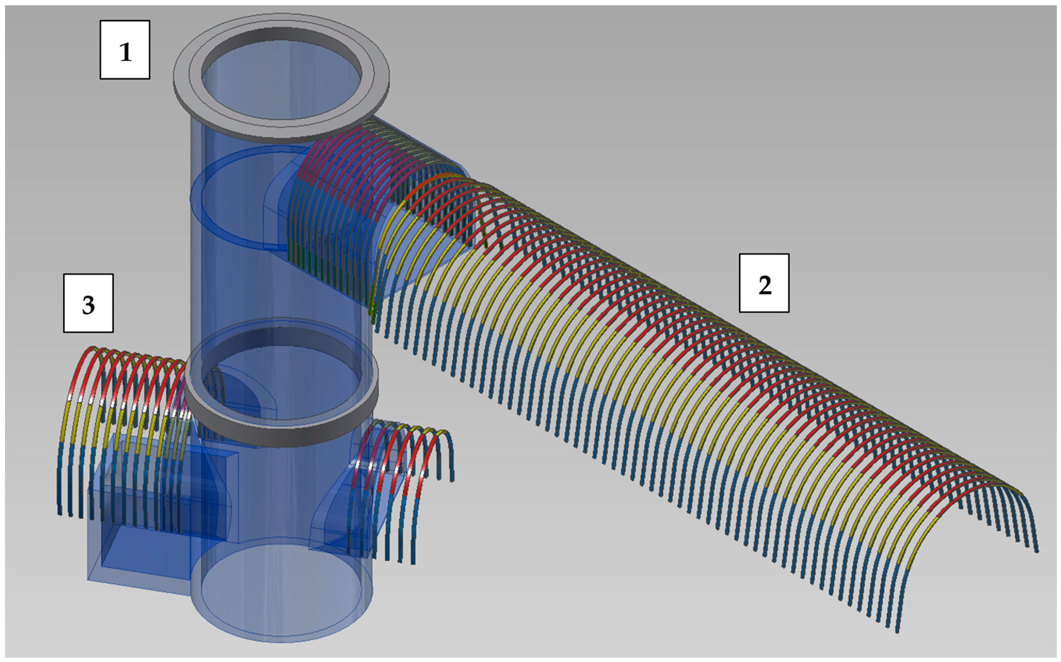
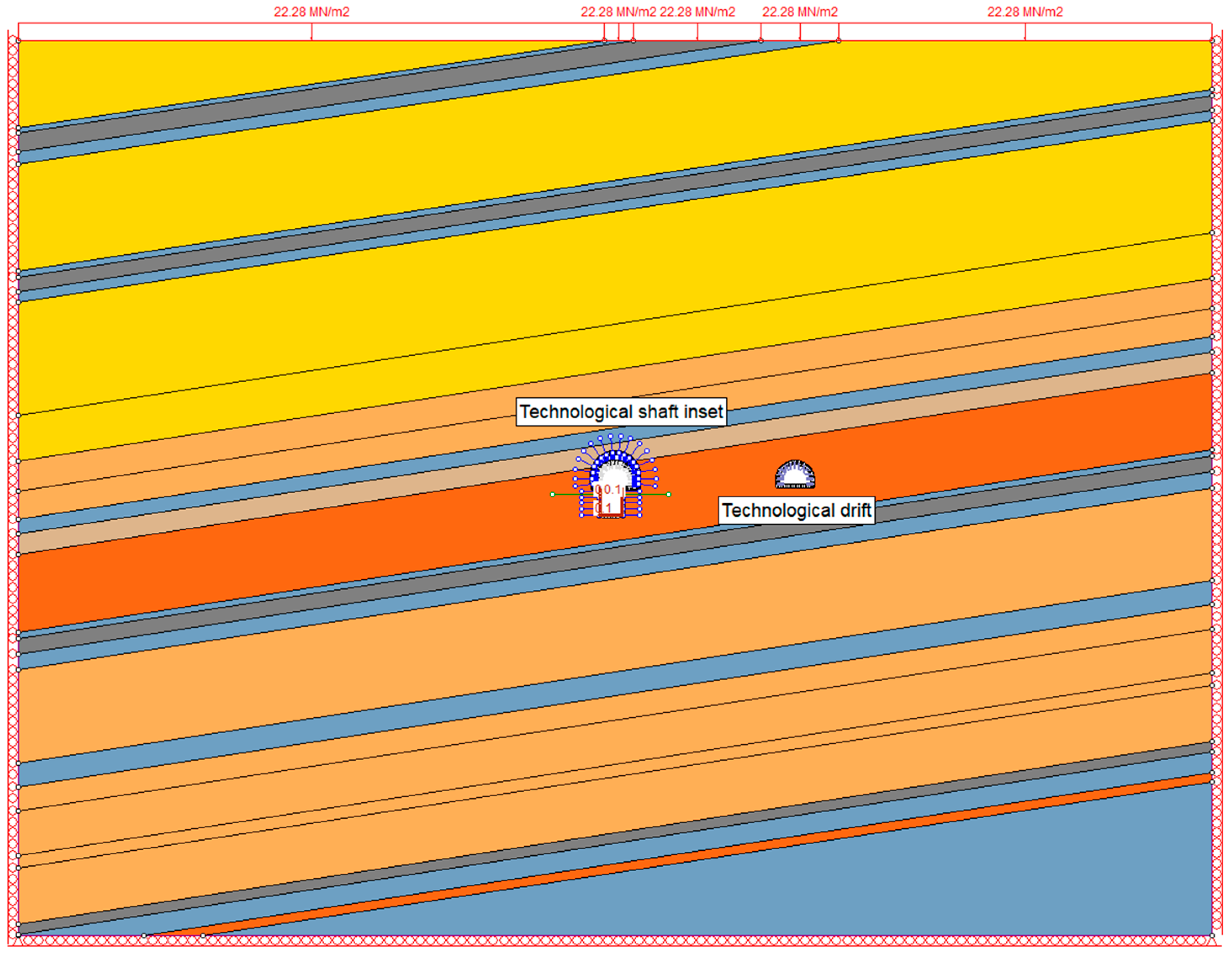
- Connecting drift I, the technological incline, and the technological drift were used as access routes to Shaft II, as well as transport routes for materials and mined rock from excavated shaft.
- Technological shaft inset was used as a loading point for materials, a discharge point for mined rock from the excavated shaft, and a location for the concrete mixing plant.
- Hoisting machine chamber with the shaft inset was used as a location for hoisting machines and mining reels.
- Connecting drift II was used as an access route to the hoisting machine chamber.
2. Rock Mass Characteristics
2.1. Geological Conditions in the Area of Shaft II
2.2. Intact Rock Parameters
2.3. Rock Mass Classifiaction
2.4. Estimation of Rock Mass Strenght Properties
2.5. Estimation of Rock Mass Deformation Modulus
2.6. In Situ Stress
3. Analytical Method of Support Design
3.1. Calculation of the Support Pressure
3.2. Determination of Support Parameters
4. Numerical Method of Support Design
4.1. Basic Assumptions and Methodology for Numerical Modeling
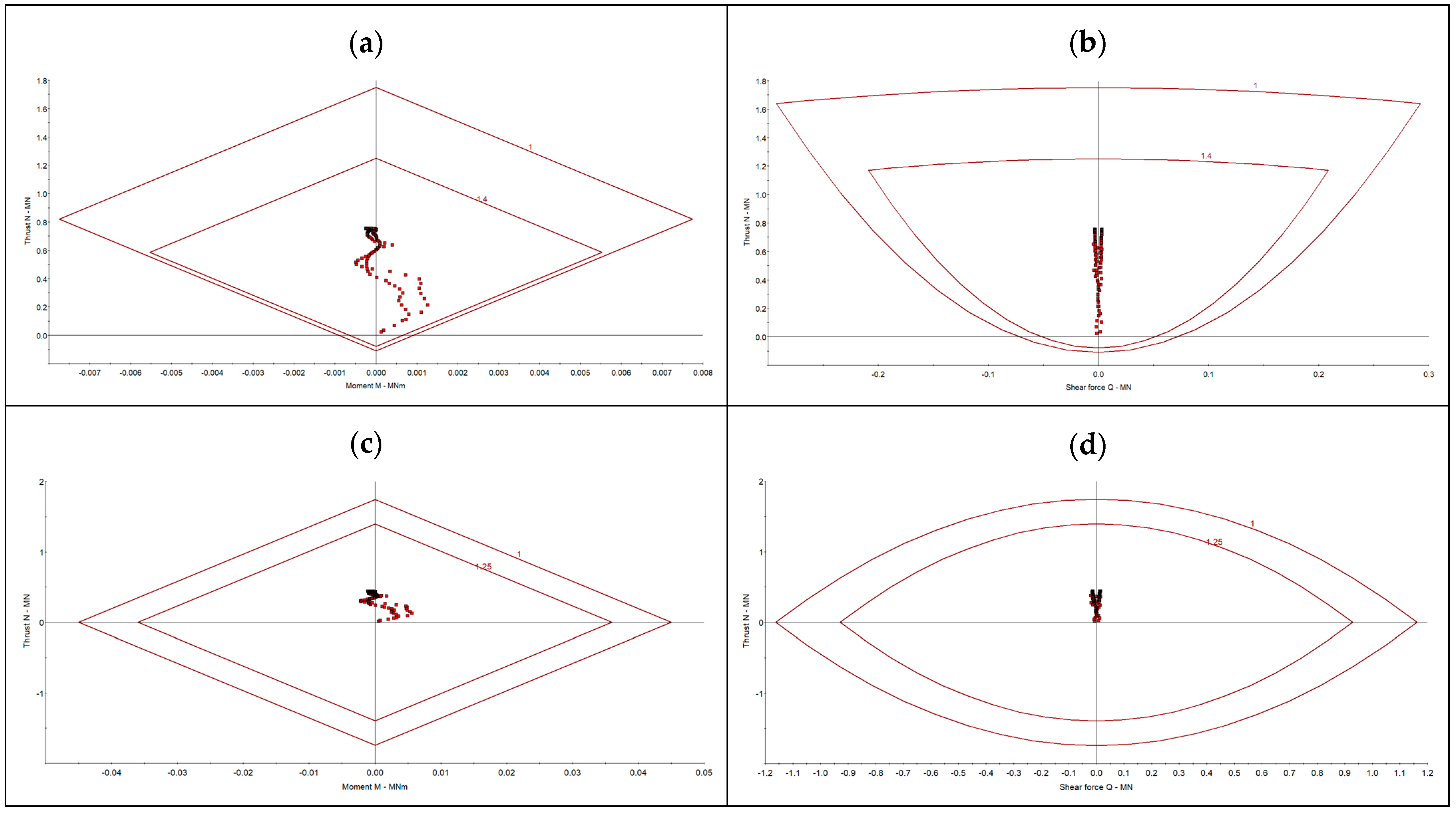
4.2. Evaluation of the Primary Support Performance
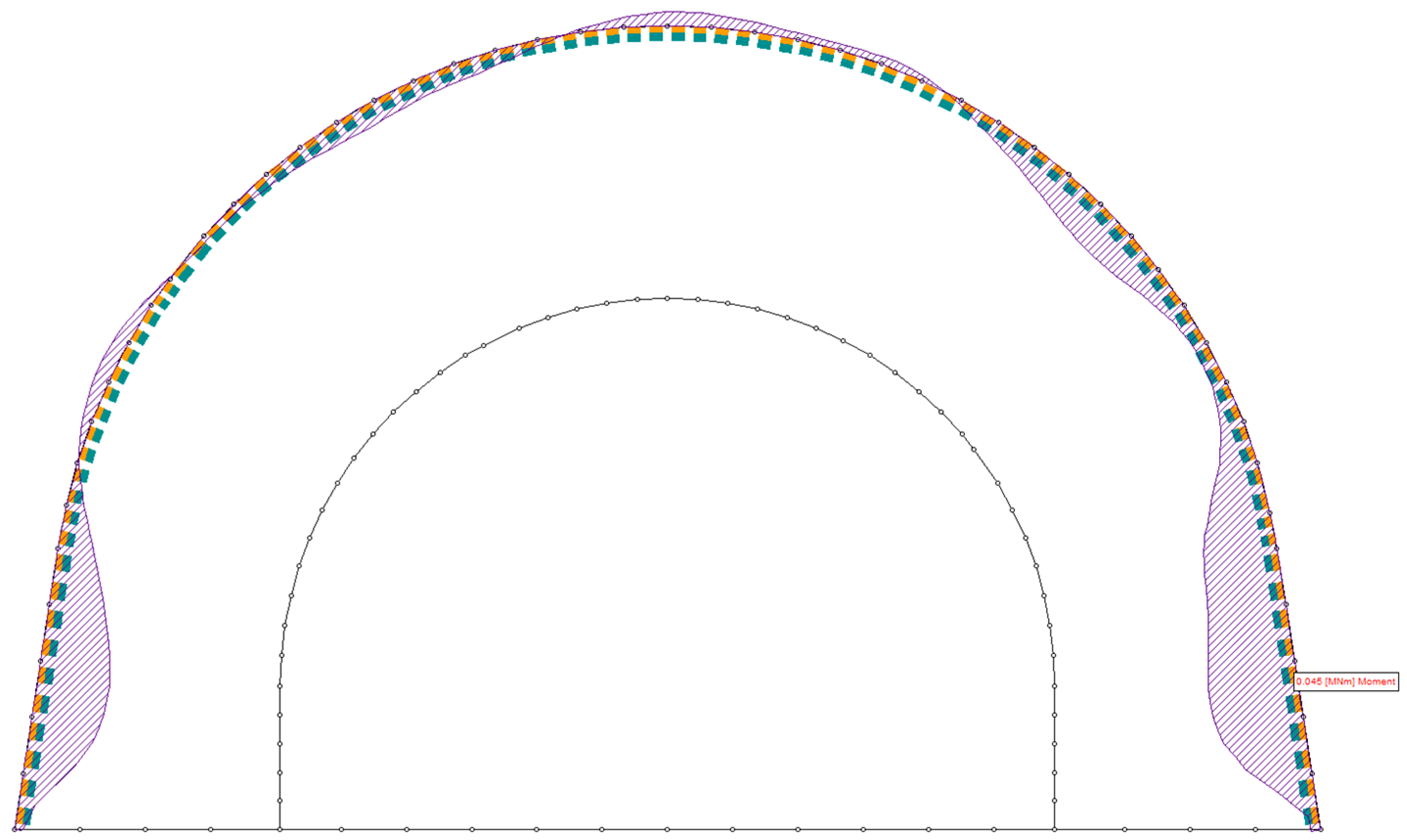
4.3. Evaluation of the Secondary Support Performance
5. Engineering Application
6. Conclusions
- The top-to-bottom deepening method was chosen for Shaft II at the Borynia Mine due to its advantages in maintaining operational continuity and excavation stability. This approach allowed for controlled shaft sinking from a sub-level, ensuring safe working conditions despite the challenging geological environment. The method was selected based on past experiences in Polish mining, where bottom-to-top techniques have seen limited application due to unfavorable rock mass conditions and logistical constraints.
- The mechanical properties of the rock mass were determined using borehole data, geological profiles, and in situ observations. The classification of surrounding formations was carried out using the Rock Mass Rating (RMR) and Geological Strength Index (GSI), providing estimates for key parameters such as rock mass cohesion, internal friction angle, and deformation modulus. These values formed the basis for subsequent analytical and numerical analyses.
- The support pressure was initially estimated using a closed-form method, based on elasto-plastic strain-softening model. The Mohr–Coulomb failure criterion was applied to estimate the transition between elastic and plastic zones, allowing for an assessment of rock mass response to excavation. The analytical approach provided a first estimate of the expected load on the support system, used subsequently in further calculations.
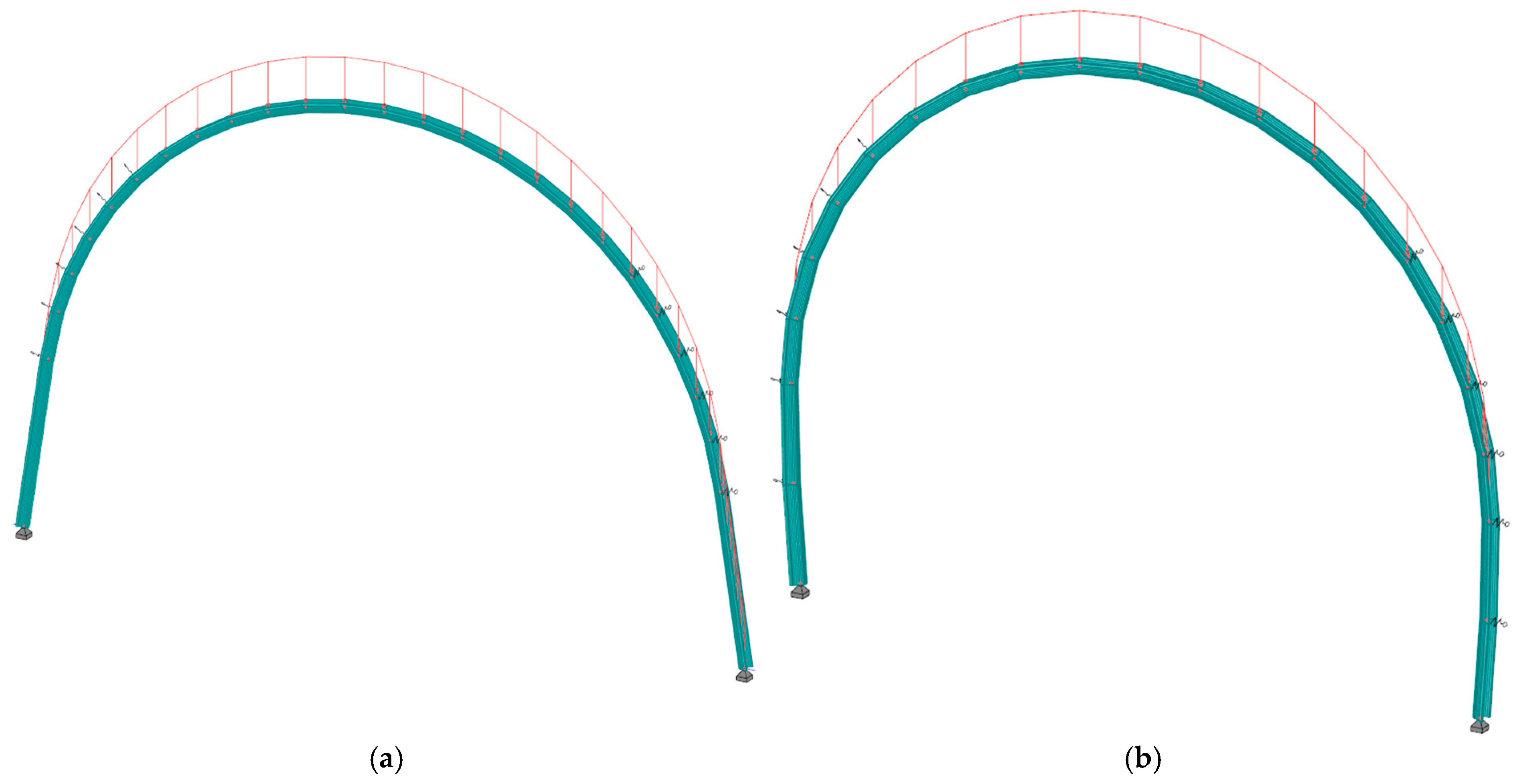
- The primary support system, consisting of yielding steel arches equipped with sliding joints, was designed based on numerical calculations of bending moments and axial forces in frame models. The optimal steel set spacing was determined to ensure required load-bearing capacity while maintaining cost-effectiveness. Additionally, the secondary support system, comprising aforementioned steel sets embedded in fiber-reinforced shotcrete, was designed based on its compressive and shear strength, ensuring long-term excavation stability.
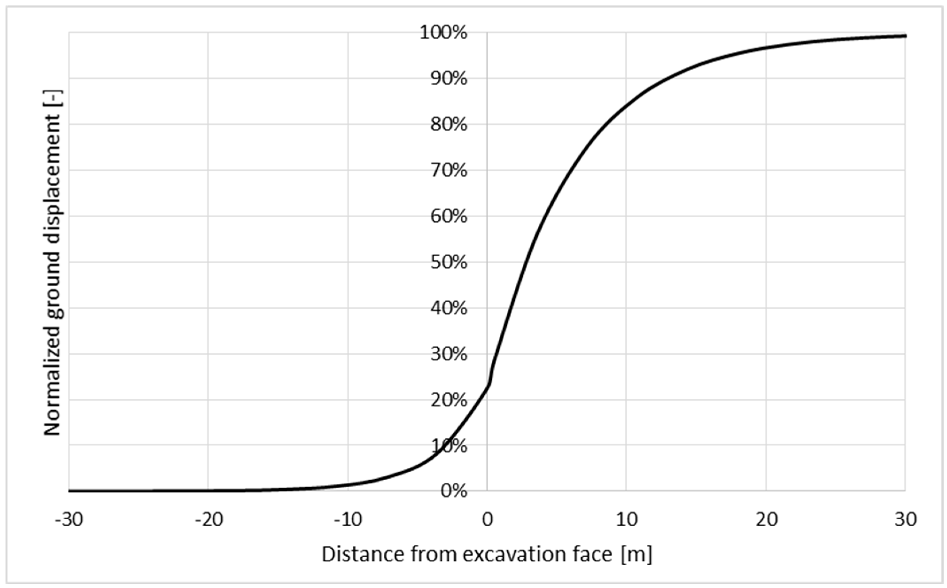
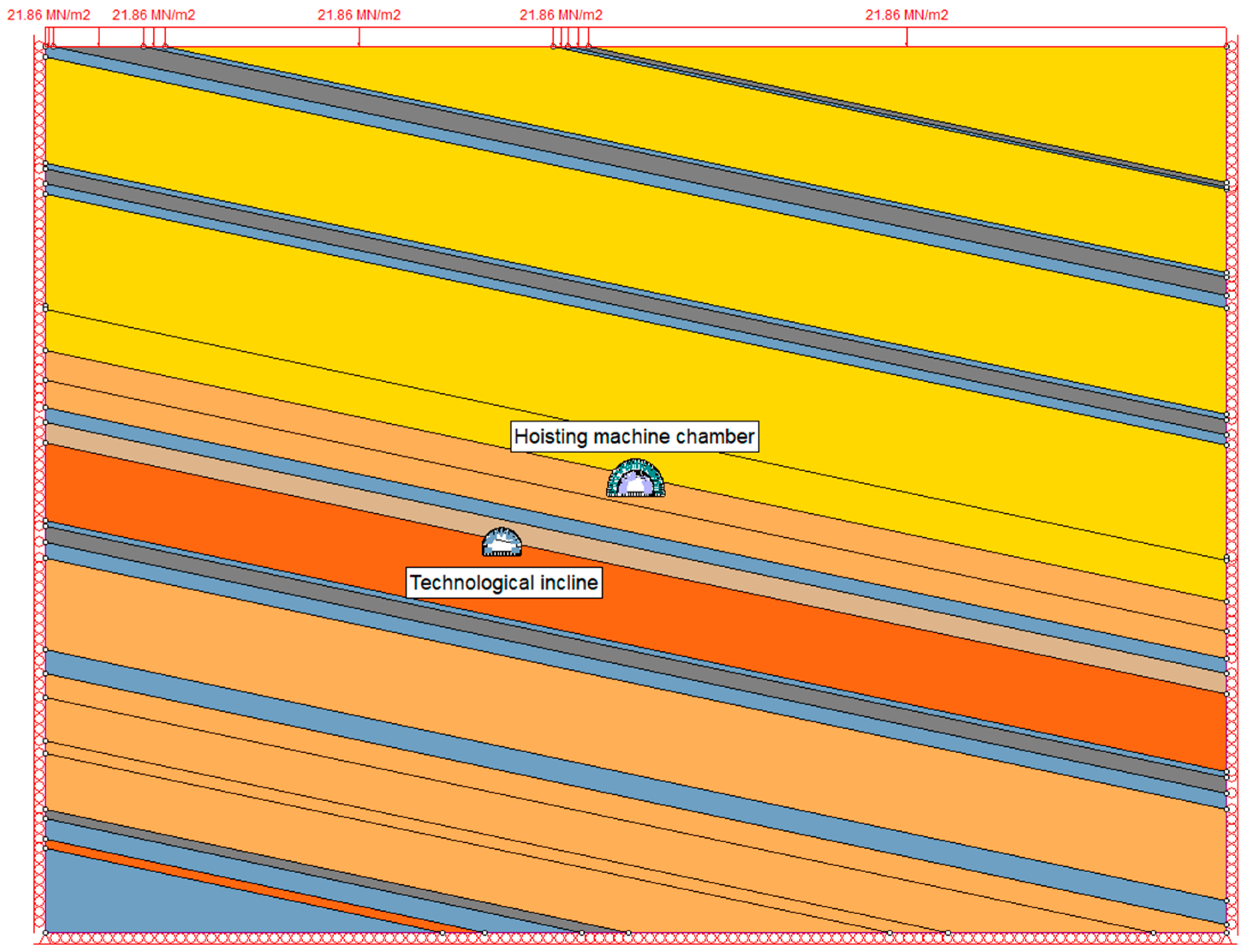
- Two-dimensional finite element models (FEM) were developed to analyze stress distribution and state of deformation around analyzed excavations. The model incorporated pre-mining stress conditions, excavation sequence effects, and rock mass properties derived from empirical classification systems. To simulate the gradual formation of the plastic zone, a longitudinal displacement profile (LDP) was applied, allowing for a more realistic assessment of ground-support interaction.
- The primary and secondary support systems were evaluated through numerical simulations. The analysis confirmed that the selected steel arches with sliding joints maintained stability under expected loads, while the composite support system of shotcrete and steel reinforcements provided long-term structural integrity. The numerical results validated the analytical calculations, ensuring that the adopted design met safety requirements.
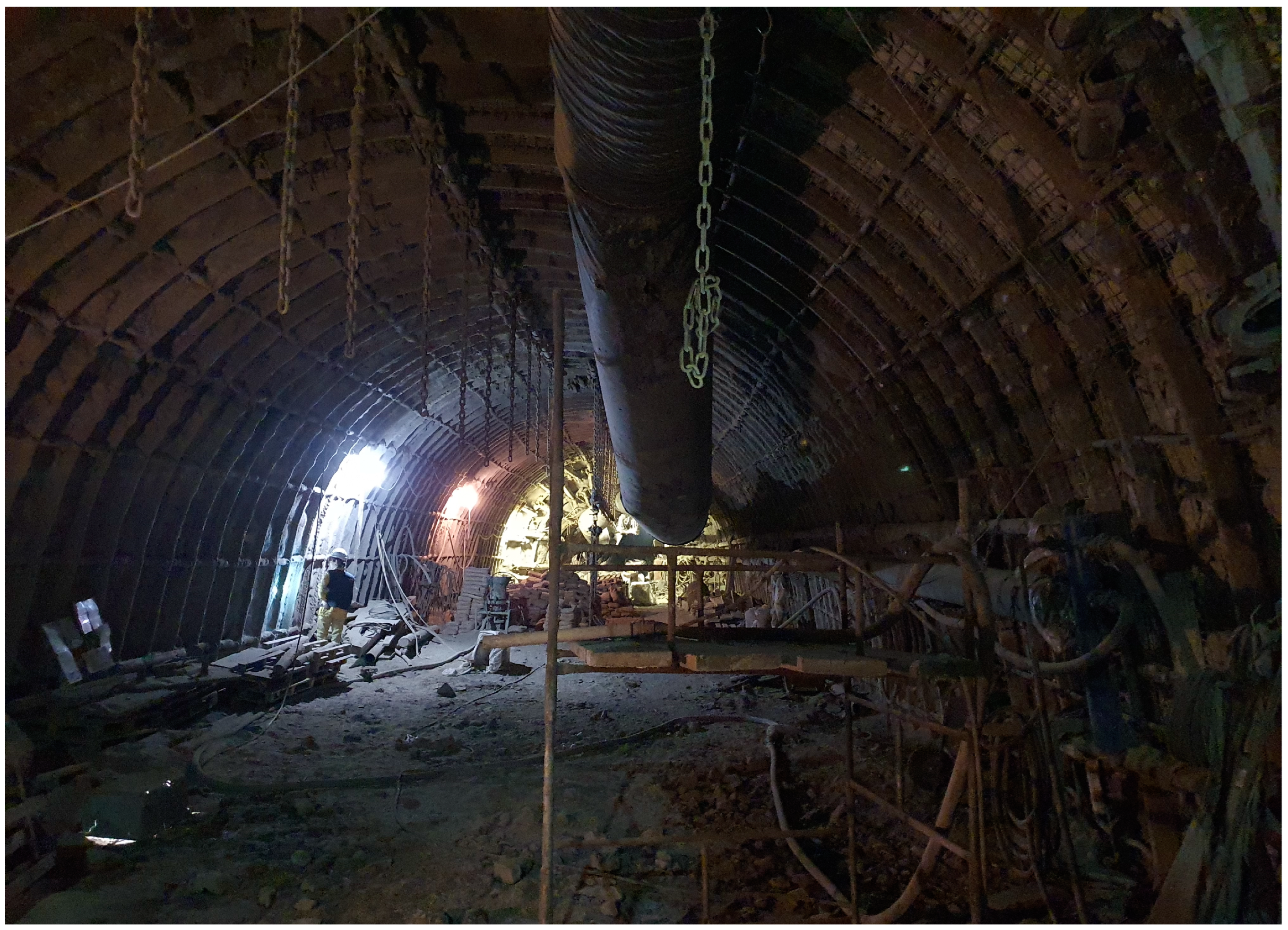
- The proposed excavation and support designs were successfully implemented during the excavation of auxiliary workings for the deepening of Shaft II. The pilot drift expansion method was applied to ensure controlled stress redistribution and maximize operational safety. In situ observations confirmed that the implemented support system performed as expected, preventing excessive deformation or rock mass failure. The results demonstrate the effectiveness of the combined analytical and numerical design approach for the design of deep mining excavations.
Author Contributions
Funding
Institutional Review Board Statement
Informed Consent Statement
Data Availability Statement
Conflicts of Interest
References
- Walewski, J. Zasady Projektowania Kopalń. Część V. Projektowanie Szybów i Szybików; Publishing House Śląsk: Katowice, Poland, 1965; pp. 660–724. [Google Scholar]
- Liu, Z.; Meng, Y. Key technologies of drilling process with raise boring method. J. Rock Mech. Geotech. Eng. 2015, 7, 385–394. [Google Scholar] [CrossRef]
- Kamiński, P.; Dyczko, A.; Prostański, D. Virtual Simulations of a New Construction of the Artificial Shaft Bottom (Shaft Safety Platform) for Use in Mine Shafts. Energies 2021, 14, 2110. [Google Scholar] [CrossRef]
- Gospodarczyk, P. Computer Simulation Usage for Verification of Deepened Shaft Artificial Bottom Construction. Arch. Min. Sci. 2015, 60, 1029–1039. [Google Scholar] [CrossRef]
- Kamiński, P. Polish Experience in Shaft Deepening and Mining Shaft Hoist Elongation. In Mining Techniques—Past, Present and Future; Soni, A., Ed.; IntechOpen: London, UK, 2021; pp. 79–96. ISBN 978-1-83962-368-4. [Google Scholar]
- Łapuszek, B.; Szyndler, J.; Kamiński, P. Wykonanie wlotu podszybia szybu ”Janina VI” na poziomie 800. Wiadomości Górnicze 2017, 68, 173–183. [Google Scholar]
- Małkowski, P.; Ostrowski, P.; Brodny, J. Analysis of Young’s modulus for Carboniferous sedimentary rocks and its relationship with uniaxial compressive strength using different methods of modulus determination. J. Sustain. Min. 2018, 17, 145–157. [Google Scholar] [CrossRef]
- Bieniawski, Z.T. Engineering Rock Mass Classifications: A Complete Manual for Engineers and Geologists in Mining, Civil, and Petroleum Engineering; Wiley: New York, NY, USA, 1989; pp. 51–72. ISBN 978-0471601722. [Google Scholar]
- Hoek, E. Strength of Rock and Rock Masses. ISRM News J. 1994, 2, 4–16. [Google Scholar]
- Hoek, E.; Kaiser, P.K.; Bawden, W.F. Support of Underground Excavations in Hard Rock; A.A. Balkema Publishers: Rotterdam, The Netherlands, 1995; pp. 27–50. ISBN 978-9054101871. [Google Scholar]
- Hoek, E.; Marinos, P. Predicting tunnel squeezing problems in weak heterogeneous rock masses. Tunn. Tunn. Int. 2000, 132, 45–51. [Google Scholar]
- Barton, N.; Lien, R.; Lunde, J. Engineering classification of rock masses for the design of tunnel support. Rock Mech. 1974, 6, 189–236. [Google Scholar] [CrossRef]
- Hoek, E.; Brown, E.T. Practical estimates of rock mass strength. Int. J. Rock Mech. Min. Sci. 1997, 34, 1165–1196. [Google Scholar] [CrossRef]
- Li, G.C.; Sun, Y.T.; Zhang, J.F.; Zhang, Q.J.; Sun, C.L.; Zhang, S.H.; Bi, R.Y. Experiment and application of coalcrete on roadway stability: A comparative analysis. Adv. Mater. Sci. Eng. 2020, 2020, 1–14. [Google Scholar] [CrossRef]
- Małkowski, P.; Ostrowski, Ł.; Bachanek, P. Modelling the Small Throw Fault Effect on the Stability of a Mining Roadway and Its Verification by In Situ Investigation. Energies 2017, 10, 2082. [Google Scholar] [CrossRef]
- Małkowski, P.; Ostrowski, Ł. Convergence monitoring as a basis for numerical analysis of changes of rock-mass quality and Hoek-Brown failure criterion parameters due to longwall excavation. Arch. Min. Sci. 2019, 64, 94–118. [Google Scholar] [CrossRef]
- Marini, D.; Zurlo, R.; Rivoltini, M.; Pizzarotti, E.M. Brenner Base Tunnel, Italian Side: Mining methods stretches—Design procedures. In Tunnels and Underground Cities. Engineering and Innovation Meet Archaeology, Architecture and Art. Volume 7: Long And Deep Tunnels; Peila, D., Viggiani, G., Celestino, T., Eds.; CRC Press: London, UK, 2020; ISBN 9780429424441. [Google Scholar] [CrossRef]
- Sebbeh-Newton, S.; Abdulazeez Shehu, S.; Ayawah, P.; Kaba, A.A.; Zabidi, H. Analytical and numerical assessment of a preliminary support design—A case study. Cogent Eng. 2021, 8, 1869367. [Google Scholar] [CrossRef]
- Azad, M.A.; Singh, S.K.; Alok, A.; Meenakshi; Shekhar, S.; Kumar, P. Geotechnical and geological studies of Adit-6 of the railway tunnel between Rishikesh and Karnprayag in India focusing on the excavation methods and design of support analysis: A case study. Arab. J. Geosci. 2022, 15, 129. [Google Scholar] [CrossRef]
- Zeqiri, K.; Ibishi, G.; Shabani, M.; Kortnik, J.; Bilir, M.E.; Geniş, M.; Yavuz, M.; Hetemi, M.; Bacak, G. Preliminary support design for underground mine adit, Artana mine, Kosovo. Min. Sci. 2021, 28, 141–159. [Google Scholar]
- Salehi, B. Cavern Design Philosophy under High Stress Rock Condition a Case Study in Sri Lanka. Am. J. Appl. Sci. 2017, 14, 406–416. [Google Scholar] [CrossRef][Green Version]
- Azad, M.A.; Naithani, A.K.; Shekhar, S.; Ahmad, S.; Singh, S.K. Tunnel Support Validation Using Numerical Modelling: A Case Study from NW, Himalaya, India. Geotech. Geol. Eng. 2023, 41, 4335–4349. [Google Scholar] [CrossRef]
- Cai, M.; Kaiser, P.K.; Tasaka, Y.; Minami, M. Determination of residual strength parameters of jointed rock masses using the GSI system. Int. J. Rock Mech. Min. Sci. 2007, 44, 247–265. [Google Scholar] [CrossRef]
- Walton, G.; Larie, D.; Alejano, L.R. On the residual strength of rocks and rockmasses. Rock Mech. Rock Eng. 2019, 52, 4821–4833. [Google Scholar] [CrossRef]
- Dressel, E.J.; Diederichs, M.S. Guidelines for estimating residual GSI and the effects of Hoek-Brown dilation on continuum 3D pillar behaviour. In Proceedings of the GeoNiagara 2021 Conference, Niagara Falls, ON, Canada, 26–29 September 2021; p. 8. [Google Scholar]
- Fischer, C.P.; Diederichs, M.S. Explicit numerical models for the prediction of plastic and weakening rockmass behaviour around a circular tunnel in isotropic and anisotropic stress conditions. IOP Conf. Ser. Earth Environ. Sci. 2023, 1124, 012061. [Google Scholar] [CrossRef]
- Rafiei Renani, H.; Cai, M. Forty-Year Review of the Hoek–Brown Failure Criterion for Jointed Rock Masses. Rock Mech. Rock Eng. 2022, 55, 439–461. [Google Scholar] [CrossRef]
- Hoek, E.; Carranza-Torres, C.; Corkum, B. Hoek-Brown failure criterion and GSI—2002 edition. In Proceedings of the 5th North American Rock Mechanics Symposium, Toronto, ON, Canada, 7–10 July 2002; pp. 267–273. [Google Scholar]
- Hoek, E.; Brown, E.T. The Hoek-Brown failure criterion and GSI—2018 edition. J. Rock Mech. Geotech. Eng. 2019, 11, 445–463. [Google Scholar] [CrossRef]
- Małkowski, P.; Niedbalski, Z. The Meaning of Average Compressive and Tensile Strength for Hoek-Brown mi Constant Determination. Arch. Min. Sci. 2024, 69, 485–508. [Google Scholar] [CrossRef]
- Arshadnejad, S. Determination of “mi” in the Hoek-Brown failure criterion of rock. Min. Sci. 2018, 25, 111–127. [Google Scholar] [CrossRef]
- Hoek, E.; Diederichs, M.S. Empirical estimation of rock mass modulus. Int. J. Rock Mech. Min. Sci. 2006, 43, 203–215. [Google Scholar] [CrossRef]
- Brady, B.H.G.; Brown, E.T. Rock Mechanics for Underground Mining, 3rd ed.; Springer Dordrecht: Dordrecht, The Netherlands, 2006; pp. 142–164. ISBN 978-1-4020-2064-3. [Google Scholar]
- Kirsch, G. Die Theorie der Elastizität und die Bedürfnisse der Festigkeitslehre. Zantralblatt Verlin Dtsch. Ingenieure 1898, 42, 797–807. [Google Scholar]
- Brown, E.T.; Bray, J.; Ladanyi, B.; Hoek, E. Ground response curves for rock tunnels. J. Geotech. Eng. 1983, 109, 15–39. [Google Scholar] [CrossRef]
- Duncan Fama, M.E. Numerical modelling of yield zones in weak rock. In Comprehensive Rock Engineering: Principles, Practice and Projects. Analysis and Design Methods; Fairhurst, C., Ed.; Pergamon Press: Oxford, UK, 1995; pp. 49–75. ISBN 978-0-08-040615-2. [Google Scholar]
- Carranza-Torres, C.; Fairhurst, C. Application of the Convergence-Confinement Method of Tunnel Design to Rock Masses that Satisfy The Hoek-Brown Failure Criterion. Tunn. Undergr. Space Technol. 2000, 15, 187–213. [Google Scholar] [CrossRef]
- PN-G-05020:1997; Podziemne Wyrobiska Korytarzowe i Komorowe. Obudowa Sklepiona. Zasady Projektowania i Obliczeń Statycznych. Polski Komitet Normalizacyjny: Warsaw, Poland, 1997.
- PN-G-05600:1998; Podziemne Wyrobiska Korytarzowe i Komorowe. Obudowa Powłokowa. Zasady Projektowania i Obliczeń Statycznych. Polski Komitet Normalizacyjny: Warsaw, Poland, 1998.
- Chudek, M.; Mateja, J.; Rułka, K. Podstawy Teoretyczne Oraz Nowe Zasady Doboru, Ustalenia Obciążeń i Wymiarowania Obudów Długotrwałych Wyrobisk Korytarzowych i Komorowych; Publishing House of Silesian University of Technology: Gliwice, Poland, 1985. [Google Scholar]
- Chudek, M.; Głuch, P.; Szczepaniak, Z. Projektowanie i Wykonywanie Wyrobisk Komorowych, 2nd ed.; Publishing House of Silesian University of Technology: Gliwice, Poland, 1991. [Google Scholar]
- Kamiński, P.; Otto, A.; Dawidziuk, P.; Malinowski, L.; Stecuła, K.; Dyczko, A. Determination of the Ground Reaction Curve for an Elasto-Plasto-Fractured Rock Mass. Appl. Sci. 2024, 14, 5409. [Google Scholar] [CrossRef]
- Rułka, K.; Mateja, J.; Kowalski, E.; Skrzyński, K.; Stałęga, S.; Wojtusiak, A.; Schinohl, J. Uproszczone Zasady Doboru Obudowy Odrzwiowej Wyrobisk Korytarzowych w Zakładach Wydobywających Węgiel Kamienny; Publishing House of Central Mining Institute: Katowice, Poland, 2001; p. 23. [Google Scholar]
- Chudek, M.; Duży, S.; Kleta, H.; Kłeczek, Z.; Stoiński, K.; Zorychta, A. Zasady Doboru i Projektowania Obudowy Wyrobisk Korytarzowych i ich Połączeń w Zakładach Górniczych Wydobywających Węgiel Kamienny; Departament of Geomechanics, Underground Construction and Surface Protection, Faculty of Mining and Geology of Silesian University of Technology: Gliwice, Poland, 2000; pp. 42–52. [Google Scholar]
- PN-B-03200:1990; Konstrukcje Stalowe. Obliczenia Statyczne i Projektowanie. Polski Komitet Normalizacyjny: Warsaw, Poland, 1990.
- Karakus, M. Appraising the methods accounting for 3D tunnelling effects in 2D plane strain FE analysis. Tunn. Undergr. Space Technol. 2007, 22, 47–56. [Google Scholar] [CrossRef]
- Vlachopoulos, N.; Diederichs, M.S. Appropriate Uses and Practical Limitations of 2D Numerical Analysis of Tunnels and Tunnel Support Response. Geotech. Geol. Eng. 2014, 32, 469–488. [Google Scholar] [CrossRef]
- Vlachopoulos, N.; Diederichs, M.S. Improved longitudinal displacement profiles for convergence confinement analysis of deep tunnels. Rock Mech. Rock Eng. 2009, 42, 131–146. [Google Scholar] [CrossRef]
- RS2 User Guide. Available online: https://www.rocscience.com/help/rs2/documentation/ (accessed on 23 January 2025).
- Tajduś, A.; Cała, M.; Tajduś, K. Geomechanika w Budownictwie Podziemnym i Tunelowaniu; Publishing House of AGH University of Science and Technology: Cracow, Poland, 2012; pp. 185–191. ISBN 978-83-7464-511-9. [Google Scholar]
- Carranza-Torres, C.; Diederichs, M.S. Mechanical analysis of a circular liner with particular reference to composite supports. For example, liners consisting of shotcrete and steel sets. Tunn. Undergr. Space Technol. 2009, 24, 506–532. [Google Scholar] [CrossRef]
- Ahmad, E. Design Considerations for Single Twin-Track Railway NATM Tunnel over Mountainous Terrain in Kenny Hill Formation. In Proceedings of the Southeast Asian Conference and Exhibition in Tunneling and Underground Space 2017, Subang Jaya, Malaysia, 18–19 April 2017. [Google Scholar]
- Terron-Almenara, J.; Skretting, E.; Holter, K.G. Design of Rock Support in Low Overburden and Hard Rock Conditions with the use of Rock Mass Classification Systems and Numerical Analyses: A Study Based on the Construction of the Hestnes Railway Tunnel, Norway. Rock. Mech. Rock. Eng. 2024, 57, 1–26. [Google Scholar] [CrossRef]
- Cui, G.; Chen, Q. Research on large deformation control technology of highly weathered carbonaceous slate tunnel. Appl. Rheol. 2023, 33, 47–53. [Google Scholar] [CrossRef]


| Lithology | Depth (m) | σc,i (MPa) | σt,i (MPa) | Ei (MPa) | RQD (%) |
|---|---|---|---|---|---|
| Medium-grained sandstone | 957.00–983.50 | 35.6 | 3.8 | 7903 | 100 |
| Mixed-grained sandstone | 983.50–988.50 | 55.2 | 5.8 | 12,254 | 80 |
| Mixed-grained sandstone | 988.50–993.20 | 64.9 | 6.8 | 14,408 | 80 |
| Claystone | 993.20–995.70 | 32.6 | 4.0 | 8932 | 65 |
| Mudstone | 995.70–999.20 | 73.9 | 8.9 | 17,145 | 70 |
| Fine-grained sandstone | 999.20–1012.20 | 67.3 | 6.9 | 14,941 | 60 |
| Lithology | Depth (m) | Rock Mass Classification | ||
|---|---|---|---|---|
| RMR | GSI | GSIr | ||
| Medium-grained sandstone | 957.00–983.50 | 72.4 | 67.4 | 27.3 |
| Mixed-grained sandstone | 983.50–988.50 | 68.3 | 63.3 | 27.1 |
| Mixed-grained sandstone | 988.50–993.20 | 69.0 | 64.0 | 27.1 |
| Claystone | 993.20–995.70 | 58.6 | 54.6 | 26.1 |
| Mudstone | 995.70–999.20 | 65.1 | 60.1 | 26.9 |
| Fine-grained sandstone | 999.20–1012.20 | 64.2 | 59.2 | 26.8 |
| Lithology | Depth (m) | Hoek–Brown | Coulomb–Mohr | |||
|---|---|---|---|---|---|---|
| m | s | a | c (MPa) | φ (°) | ||
| Medium-grained sandstone | 957.00–983.50 | 2.668 | 0.027 | 0.502 | 2.60 | 32.56 |
| Mixed-grained sandstone | 983.50–988.50 | 2.332 | 0.017 | 0.502 | 2.94 | 34.89 |
| Mixed-grained sandstone | 988.50–993.20 | 2.396 | 0.018 | 0.502 | 3.23 | 36.31 |
| Claystone | 993.20–995.70 | 1.025 | 0.002 | 0.504 | 1.58 | 24.52 |
| Mudstone | 995.70–999.20 | 1.434 | 0.005 | 0.503 | 2.64 | 33.20 |
| Fine-grained sandstone | 999.20–1012.20 | 1.570 | 0.005 | 0.503 | 2.59 | 33.17 |
| Lithology | Depth (m) | Hoek–Brown | Coulomb–Mohr | |||
|---|---|---|---|---|---|---|
| m | s | a | c (MPa) | φ (°) | ||
| Medium-grained sandstone | 957.00–983.50 | 0.637 | 0.000 | 0.527 | 1.27 | 21.19 |
| Mixed-grained sandstone | 983.50–988.50 | 0.640 | 0.000 | 0.527 | 1.50 | 24.09 |
| Mixed-grained sandstone | 988.50–993.20 | 0.643 | 0.000 | 0.527 | 1.61 | 25.18 |
| Claystone | 993.20–995.70 | 0.550 | 0.000 | 0.529 | 1.14 | 19.62 |
| Mudstone | 995.70–999.20 | 0.576 | 0.000 | 0.528 | 1.61 | 25.13 |
| Fine-grained sandstone | 999.20–1012.20 | 0.650 | 0.000 | 0.528 | 1.64 | 25.36 |
| Lithology | Depth (m) | Ei (MPa) | Em (MPa) |
|---|---|---|---|
| Medium-grained sandstone | 957.00–983.50 | 7903 | 5391 |
| Mixed-grained sandstone | 983.50–988.50 | 12,254 | 7285 |
| Mixed-grained sandstone | 988.50–993.20 | 14,408 | 8788 |
| Claystone | 993.20–995.70 | 8932 | 1820 |
| Mudstone | 995.70–999.20 | 17,145 | 6136 |
| Fine-grained sandstone | 999.20–1012.20 | 14,941 | 5077 |
| Parameter | Symbol | Unit | A | B |
|---|---|---|---|---|
| 1. Input parameters | ||||
| Peak cohesive strength of the rock mass | c | MPa | 2.76 | 2.87 |
| Post-peak cohesive strength of the rock mass | c′ | MPa | 1.38 | 1.54 |
| Peak internal friction angle of the rock mass | φ | ° | 33.64 | 34.07 |
| Post-peak internal friction angle of the rock mass | φ′ | ° | 22.49 | 24.26 |
| Rock mass deformation modulus | E | MPa | 6286 | 7261 |
| Rock mass Poisson’s ratio | ν | - | 0.18 | 0.19 |
| Average bulk weight of the overburden rock | γo | MN/m3 | 0.024 | 0.024 |
| Overburden thickness | H | m | 986.5 | 1003.4 |
| Excavation cross-sectional area | A | m2 | 39.53 | 57.69 |
| Yielding force of the sliding joint | Nj | MN | 0.29 | 0.35 |
| Steel set spacing | e | m | 0.60 | 0.50 |
| Average bulk weight of the roof rocks | γr | MN/m3 | 0.024 | 0.024 |
| Partial load factor according to PN-G-05600 | n | - | 1.20 | 1.20 |
| Distance between neighboring excavations | xs | m | 15.15 | 23.00 |
| Width of the adjacent excavation | wa | m | 5.90 | 5.90 |
| 2. Calculation results | ||||
| Far field (in situ) stress | pz | MPa | 23.68 | 24.08 |
| Equivalent excavation radius | req | m | 3.55 | 4.29 |
| Peak compressive strength of the rock mass | Rc | MPa | 10.30 | 10.81 |
| Post-peak compressive strength of the rock mass | Rc′ | MPa | 4.11 | 4.77 |
| Computational factor | ϐ | - | 2.48 | 2.55 |
| Radial stress at the boundary between plastic and elastic zone | pg | MPa | 8.26 | 8.21 |
| Active support pressure | pa | MPa | 0.14 | 0.16 |
| Radius of the plastic zone | rl | m | 7.06 | 8.03 |
| Impact factor of the adjacent exavation | ks | m | 1.08 | 1.04 |
| Charasteristic value of the static support pressure | qzN | MPa | 0.085 | 0.090 |
| Design value of the static support pressure | qzo | MPa | 0.109 | 0.113 |
| Parameter | Symbol | Unit | A | B |
|---|---|---|---|---|
| 1. Input parameters | ||||
| Section type | - | - | V29 | V36 |
| Steel grade | - | - | S480W | S480W |
| Maximum value of the bending moment | Mmax | MNm | 0.0168 | 0.0147 |
| Corresponding value of the axial force | Ncor | MN | 0.2962 | 0.2851 |
| Value of the axial force in the sliding joint | N | MN | 0.4780 | 0.5147 |
| Cross-sectional area of the V-profile | A | m2 | 0.00363 | 0.00452 |
| Elastic section modulus of the V-profile | Wx | m3 | 0.0000875 | 0.0001276 |
| Yielding force of the sliding joint | Nj | MN | 0.29 | 0.35 |
| Radius of gyration of the V-profile | ix | m | 0.0400 | 0.0452 |
| Characteristic yield strength of steel | fyk | MPa | 480 | 480 |
| Design yield strength of steel | fyd | MPa | 384 | 384 |
| Characteristic ultimate tensile strength of steel | ft | MPa | 650 | 650 |
| Unsupported length of the steel set | l | m | 6.72 | 6.60 |
| Shape factor | m | - | 1.40 | 1.40 |
| Support working condition factor | m1 | - | 1.50 | 1.50 |
| Material plasticity coefficient | n1 | - | 0.35 | 0.35 |
| 2. Calculation results | ||||
| Slenderness ratio according to PN-B-03200 | λ | - | 84.0 | 74.4 |
| Reference slenderness ratio according to PN-B-03200 | λp | - | 48.3 | 48.3 |
| Reduction factor according to PN-B-03200 | ϕ | - | 0.27 | 0.33 |
| Max. steel set spacing due to profile strength | e1 | m | 0.913 | 1.117 |
| Max. steel set spacing due to sliding joint capacity | e2 | m | 0.607 | 0.680 |
| Maximum steel set spacing | emax | m | 0.607 | 0.680 |
| Steel set spacing adopted for further calculations | e | m | 0.600 | 0.500 |
| Parameter | Symbol | Unit | A | B |
|---|---|---|---|---|
| 1. Input parameters | ||||
| Contour radius of the excavation opening | rw | m | 4.58 | 3.87 |
| Characteristic compressive strength of shotcrete | fck | MPa | 35.00 | 40.00 |
| Characteristic tensile strength of shotcrete | fctd | MPa | 2.20 | 2.50 |
| Partial safety factor for fiber-reinforced shotcrete | γc | - | 1.40 | 1.40 |
| Design compressive strength of shotcrete | fcd | MPa | 25.00 | 28.57 |
| Desing tensile strength of shotcrete | fctd | MPa | 1.57 | 1.79 |
| Shotcrete thickness | g | m | 0.05 | 0.05 |
| Characteristic value of the ultimate strength of steel | fyk | MPa | 650 | 650 |
| Partial safety factor for steel | γs | - | 1.25 | 1.25 |
| Design value of the ultimate strength of steel | fd | MPa | 520 | 520 |
| Cross-sectional area of the steel set profile | A | m2 | 0.00363 | 0.00452 |
| Steel set spacing | e | m | 0.600 | 0.500 |
| 2. Calculation results | ||||
| Support capacity due to compression failure | psup1 | MPa | 0.960 | 1.584 |
| Support capacity due to shear failure | psup2 | MPa | 0.481 | 0.821 |
| Parameter | Symbol | Unit | A | B |
|---|---|---|---|---|
| 1. Input parameters | ||||
| Section type | - | - | V29 | V36 |
| Steel grade | - | - | S480W | S480W |
| Maximum value of the bending moment | Mmax | MNm | 0.0045 | 0.0119 |
| Steel set spacing | e | m | 0.600 | 0.500 |
| Cross-sectional area of the V-profile | A | m2 | 0.000363 | 0.00452 |
| Elastic section modulus of the V-profile | Wx | m3 | 0.0000875 | 0.0001276 |
| Radius of gyration of the V-profile | ix | m | 0.0400 | 0.0452 |
| Characteristic yield strength of steel | fyk | MPa | 480 | 480 |
| Design yield strength of steel | fyd | MPa | 384 | 384 |
| Characteristic ultimate tensile strength of steel | ft | MPa | 650 | 650 |
| Shape factor | m | - | 1.40 | 1.40 |
| Support working condition factor | m1 | - | 1.50 | 1.30 |
| Material plasticity coefficient | n1 | - | 0.35 | 0.35 |
| 2. Calculation results | ||||
| Strain ratio of the steel set | k | - | 0.687 | 0.900 |
Disclaimer/Publisher’s Note: The statements, opinions and data contained in all publications are solely those of the individual author(s) and contributor(s) and not of MDPI and/or the editor(s). MDPI and/or the editor(s) disclaim responsibility for any injury to people or property resulting from any ideas, methods, instructions or products referred to in the content. |
© 2025 by the authors. Licensee MDPI, Basel, Switzerland. This article is an open access article distributed under the terms and conditions of the Creative Commons Attribution (CC BY) license (https://creativecommons.org/licenses/by/4.0/).
Share and Cite
Kamiński, P.; Otto, A.; Dawidziuk, P.; Dyczko, A.; Prostański, D. Study on the Design and Construction Methods of Auxiliary Workings for the Deepening of Shaft II in the Borynia Mine. Appl. Sci. 2025, 15, 3131. https://doi.org/10.3390/app15063131
Kamiński P, Otto A, Dawidziuk P, Dyczko A, Prostański D. Study on the Design and Construction Methods of Auxiliary Workings for the Deepening of Shaft II in the Borynia Mine. Applied Sciences. 2025; 15(6):3131. https://doi.org/10.3390/app15063131
Chicago/Turabian StyleKamiński, Paweł, Aleksandra Otto, Piotr Dawidziuk, Artur Dyczko, and Dariusz Prostański. 2025. "Study on the Design and Construction Methods of Auxiliary Workings for the Deepening of Shaft II in the Borynia Mine" Applied Sciences 15, no. 6: 3131. https://doi.org/10.3390/app15063131
APA StyleKamiński, P., Otto, A., Dawidziuk, P., Dyczko, A., & Prostański, D. (2025). Study on the Design and Construction Methods of Auxiliary Workings for the Deepening of Shaft II in the Borynia Mine. Applied Sciences, 15(6), 3131. https://doi.org/10.3390/app15063131


