
Numerical Modeling and Theoretical Analysis of Deformation Characteristics of Non-Equal-Width Retained Walls


Abstract
1. Introduction
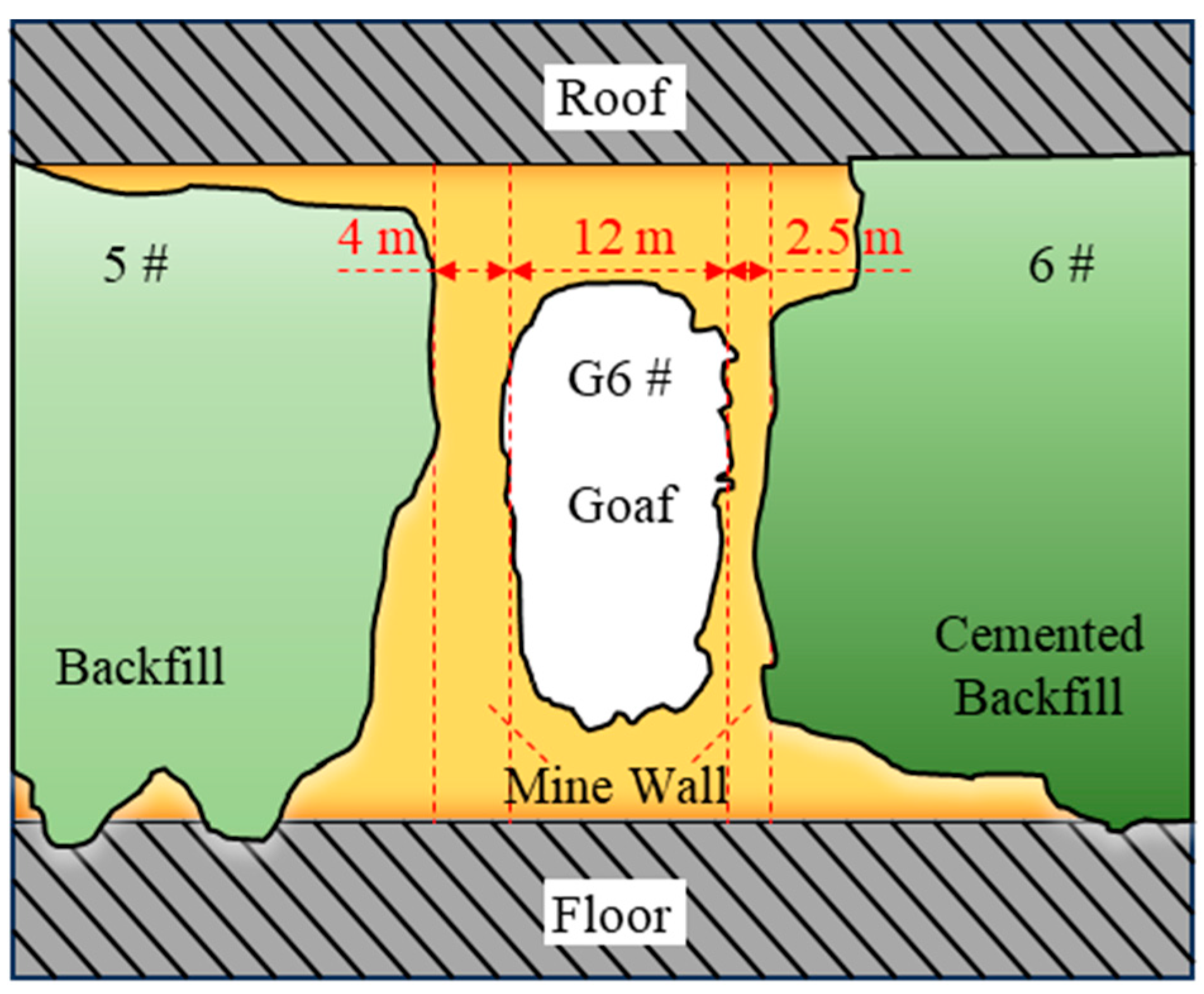
2. Project Overview and Mining Methods
3. Mechanical Modeling of the Permanent Thin Wall
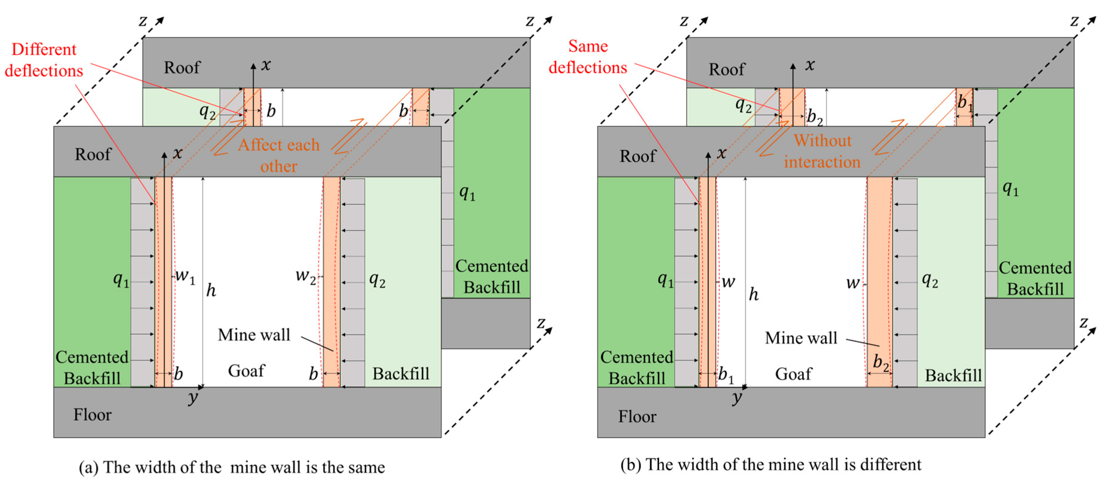
3.1. Mechanical Model of the Thin Wall When Using One Backfill Material
3.2. Mechanical Model of the Thin Wall When Using Two Backfill Materials
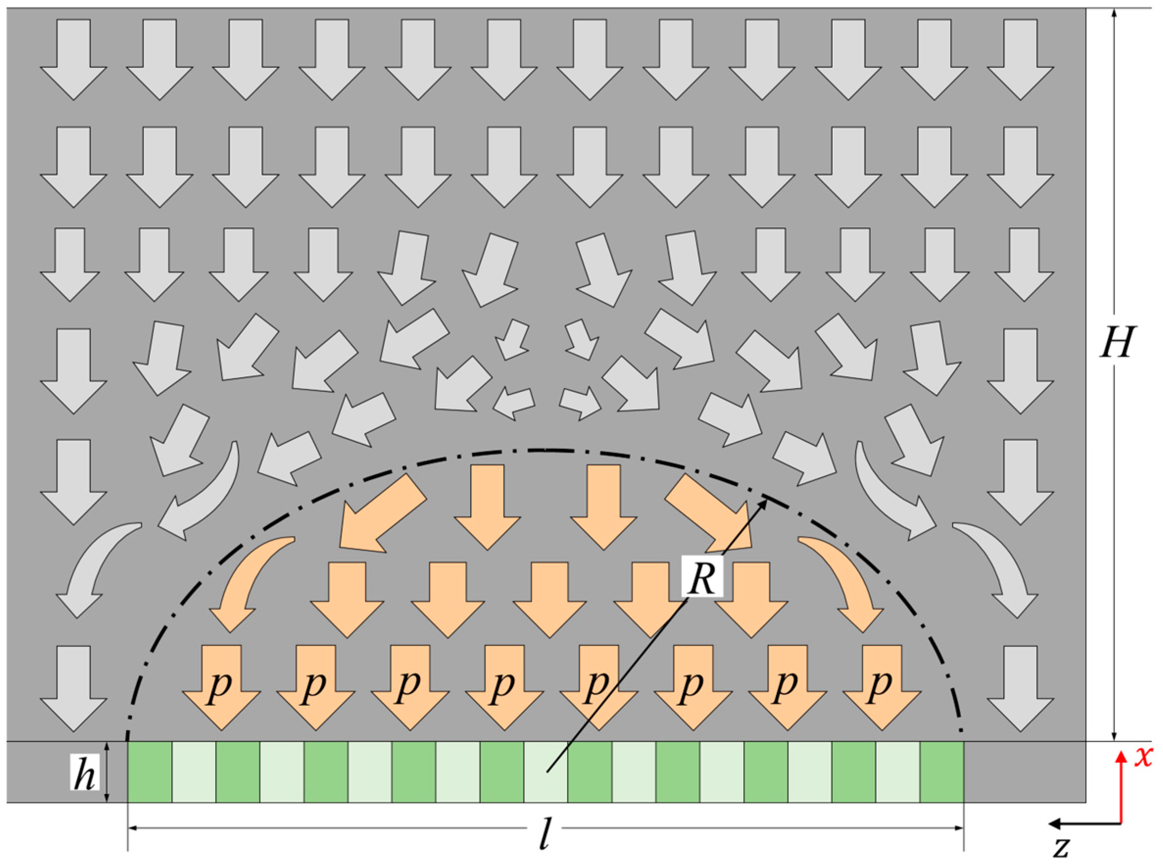
3.3. Optimization of the Width for the Thin Wall
4. Numerical Simulation and Engineering Verification
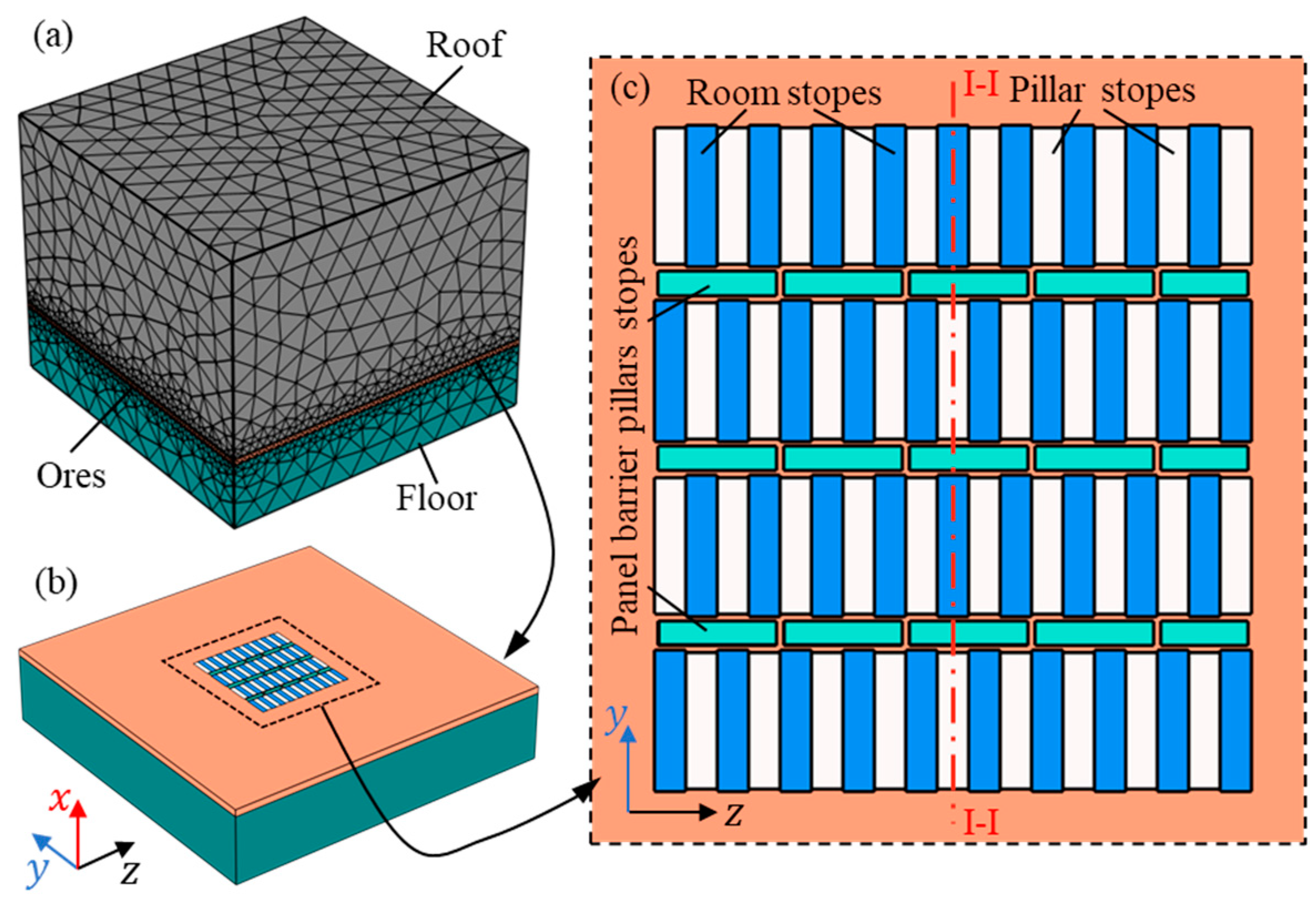
4.1. Numerical Model and Initial Conditions
4.2. Analysis of Simulation Results
4.3. Verification Against Filed Data
5. Conclusions
Author Contributions
Funding
Institutional Review Board Statement
Informed Consent Statement
Data Availability Statement
Conflicts of Interest
References
- Yao, B.; Wei, J.; Wang, D.; Ma, D.; Chen, Z. Numerical study on seepage property of karst collapse columns under particle migration. CMES Comput. Model. Eng. Sci. 2013, 91, 81–100. [Google Scholar]
- Yang, Z.; Tao, M.; Fei, W.; Yin, T.; Ranjith, P.G. Grain-based coupled thermo-mechanical modeling for stressed heterogeneous granite under thermal shock. Undergr. Space 2025, 20, 174–196. [Google Scholar] [CrossRef]
- Yang, Z.; Tao, M.; Memon, M.B.; Zhuang, D.; Zhao, Y. Microwave irradiation-induced deterioration of rock mechanical properties and implications for mechanized hard rock excavation. J. Rock Mech. Geotech. Eng. 2025, 17, 275–290. [Google Scholar] [CrossRef]
- Bai, J.; Dou, L.; Li, J.; Zhou, K.; Cao, J.; Kan, J. Mechanism of coal burst triggered by Mining-Induced fault slip under High-Stress conditions: A case study. Front. Earth Sci. 2022, 10, 884974. [Google Scholar] [CrossRef]
- Zhao, Y.; Tao, M.; Du, K.; Wu, Y.; Wu, C. Development and application of gas adsorption model for coal based on particle flow code. Gas Sci. Eng. 2023, 110, 204858. [Google Scholar] [CrossRef]
- Tuncay, D.; Tulu, I.; Klemetti, T. Re-analysis of abutment angle method for moderate and deep cover retreat room and pillar mines and investigation of loading mechanics using finite volume modeling. Rock Mech. Rock Eng. 2021, 54, 3447–3468. [Google Scholar] [CrossRef]
- Rastiello, G.; Federico, F.; Screpanti, S. New soft rock pillar strength formula derived through parametric FEA using a critical state plasticity model. Rock Mech. Rock Eng. 2015, 48, 2077–2091. [Google Scholar] [CrossRef]
- Naghadehi, M.; Mikaeil, R.; Ataei, M. The application of fuzzy analytic hierarchy process (FAHP) approach to selection of optimum underground mining method for Jajarm Bauxite Mine, Iran. Expert Syst. Appl. 2009, 36, 8218–8226. [Google Scholar] [CrossRef]
- Guo, J.; Cheng, X.; Lu, J.; Zhao, Y.; Xie, X. Research on factors affecting mine wall stability in isolated pillar mining in deep mines. Minerals 2022, 12, 623. [Google Scholar] [CrossRef]
- Sari, M.; Yilmaz, E.; Kasap, T. Long-term ageing characteristics of cemented paste backfill: Usability of sand as a partial substitute of hazardous tailings. J. Clean. Prod. 2023, 401, 136723. [Google Scholar] [CrossRef]
- Huang, X.; Cai, X.; Bo, J.; Li, S.; Qi, W. Experimental study of the influence of gradation on the dynamic properties of centerline tailings sand. Soil Dyn. Earthq. Eng. 2021, 151, 106993. [Google Scholar] [CrossRef]
- Gao, S.; Li, W.; Yuan, K.; Rong, C. Properties and application of thixotropic cement paste backfill with molybdenum tailings. J. Clean. Prod. 2023, 391, 136169. [Google Scholar] [CrossRef]
- Li, J.; Huang, Y.; Qi, W.; Kong, G.; Song, T. Loose gangues backfill body’s acoustic emissions rules during compaction test: Based on solid backfill mining. Comput. Model. Eng. Sci. 2018, 115, 85–103. [Google Scholar]
- Hou, C.; Zhu, W.; Yan, B.; Yang, L.; Du, J.; Niu, L. Mechanical behavior of backfilled pillar under biaxial loading. J. Cent. South Univ. 2023, 30, 1191–1204. [Google Scholar] [CrossRef]
- Wang, H.; Poulsen, B.; Shen, B.; Xue, S.; Jiang, Y. The influence of roadway backfill on the coal pillar strength by numerical investigation. Int. J. Rock Mech. Min. Sci. 2011, 48, 443–450. [Google Scholar] [CrossRef]
- Hou, C.; Zhu, W.; Yan, B.; Guan, K.; Niu, L. Analytical and experimental study of cemented backfill and pillar interactions. Int. J. Geomech. 2019, 19, 04019080. [Google Scholar] [CrossRef]
- Yan, B.; Ren, F.; Cai, M.; Qiao, C. Influence of new hydrophobic agent on the mechanical properties of modified cemented paste backfill. J. Mater. Res. Technol. 2019, 8, 5716–5727. [Google Scholar] [CrossRef]
- Lu, B.; Li, Y.; Fang, S.; Lin, H.; Zhu, Y. Cemented backfilling mining technology for gently inclined coal seams using a continuous mining and continuous backfilling method. Shock. Vib. 2021, 2021, 6652309. [Google Scholar] [CrossRef]
- Wang, X.; Zhang, J.; Li, M.; Gao, F.; Taheri, A.; Huo, B.; Jin, L. Expansion properties of cemented foam backfill utilizing coal gangue and fly ash. Minerals 2022, 12, 763. [Google Scholar] [CrossRef]
- Zhu, W.; Yu, S.; Xuan, D.; Shan, Z.; Xu, J. Experimental study on excavating strip coal pillars using caving zone backfill technology. Arab. J. Geosci. 2018, 11, 554. [Google Scholar] [CrossRef]
- Wang, J.; Qiao, D.; Han, R.; Li, G.; Xie, J. Strength model of cemented backfill in subsequent filling at the stage of open stope and its application. Rock Soil Mech. 2019, 40, 1105–1112. [Google Scholar] [CrossRef]
- Du, X.; Feng, G.; Qi, T.; Guo, Y.; Zhang, Y.; Wang, Z. Failure characteristics of large unconfined cemented gangue backfill structure in partial backfill mining. Constr. Build. Mater. 2019, 194, 257–265. [Google Scholar] [CrossRef]
- Le, Z.; Yu, Q.; Yang, T.; Cao, Y.; Zheng, H.; Deng, W. Compressive bearing and force transmission characteristics of granular backfill under lateral confinement. Rock Soil Mech. 2023, 43, 362–372. [Google Scholar] [CrossRef]
- Wu, D.; Guo, W.; Luo, F.; Li, M.; Wen, P. Stiffness of gangue backfilling body in goaf and its influence mechanism on rock strata control and stress evolution in gangue backfill mining. Environ. Sci. Pollut. Res. 2023, 30, 61789–61807. [Google Scholar] [CrossRef]
- Wang, J.; Fu, J.; Song, W.; Zhang, Y. Mechanical properties, damage evolution, and constitutive model of rock-encased backfill under uniaxial compression. Constr. Build. Mater. 2021, 285, 122898. [Google Scholar] [CrossRef]
- Zhu, X.; Guo, G.; Liu, H.; Peng, X.; Yang, X. Stability analysis of the composite support pillar in backfill-strip mining using particle flow simulation method. Environ. Earth Sci. 2022, 81, 124. [Google Scholar] [CrossRef]
- He, M.; Wang, Q. Excavation compensation method and key technology for surrounding rock control. Eng. Geol. 2022, 307, 106784. [Google Scholar] [CrossRef]
- Yang, Y.; Zhao, Y.; Ma, J.; Han, P. Study on stability and bearing characteristics of macroscopic pressure arch of surrounding rock in western deep buried stope of China. Front. Earth Sci. 2023, 11, 1125689. [Google Scholar] [CrossRef]
- Guo, J.; Zhao, Y.; Zhang, W.; Xie, X. Stress analysis of mine wall in panel barrier pillar-stope under multi-directional loads. J. Cent. South Univ. (Sci. Technol.) 2018, 49, 3020–3028. [Google Scholar] [CrossRef]
- Tao, M.; Zhao, Y.; Guo, J. Arch model of roof and optimization of roof-contacted filling rate in two-step mining. Trans. Nonferrous Met. Soc. China 2023, 33, 1893–1905. [Google Scholar] [CrossRef]


| Name | Density (kg·m−3) | Elastic Modulus (GPa) | Cohesion (MPa) | Internal Friction Angle (°) | Poisson Ratio | Compressive Strength (MPa) | Tensile Strength (MPa) |
|---|---|---|---|---|---|---|---|
| Ores | 3020 | 28.14 | 25.63 | 46.2 | 0.301 | 102.86 | 2.02 |
| Roof rock | 2600 | 6.13 | 15.20 | 35.1 | 0.327 | 51.32 | 1.16 |
| Floor rock | 2620 | 13.48 | 20.37 | 43.8 | 0.210 | 86.33 | 1.47 |
| Cemented Backfill | 1740 | 0.85 | 1.02 | 34.6 | 0.311 | 2.19 | 0.23 |
| Backfill | 1640 | 0.41 | - | 22.1 | 0.403 | 0 | - |
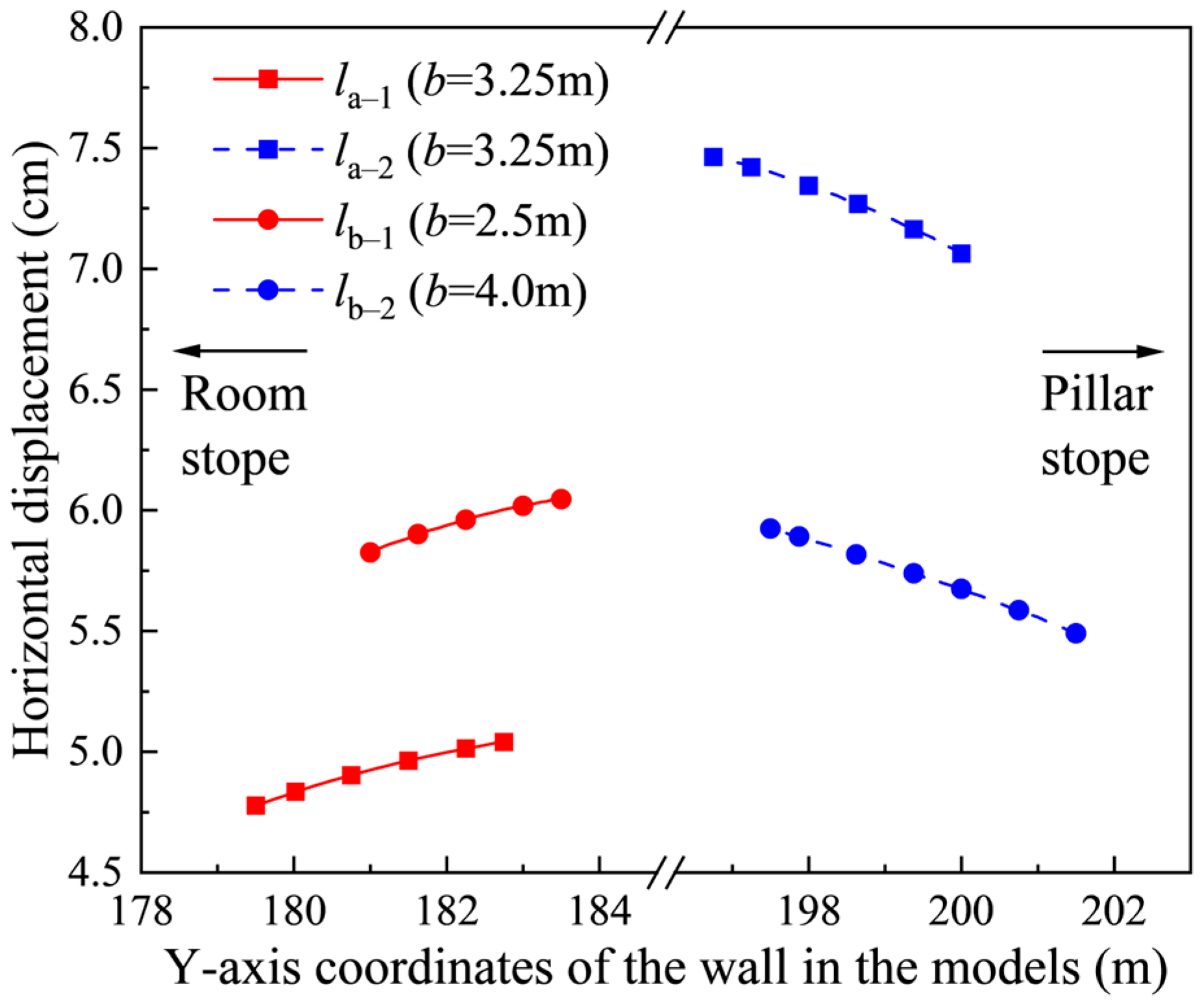
| Name | Starting Point Coordinates (P1) | Ending Point Coordinates (P2) | Width | Average Horizontal Displacement |
|---|---|---|---|---|
| la−1 | (12.5, 179.5) | (12.5, 182.75) | 3.25 | 4.92 |
| la−2 | (12.5, 200) | (12.5, 196.75) | 3.25 | 7.28 |
| lb−1 | (12.5, 181) | (12.5, 183.5) | 2.50 | 5.96 |
| lb−2 | (12.5, 201.5) | (12.5, 197.5) | 4.00 | 5.72 |
Disclaimer/Publisher’s Note: The statements, opinions and data contained in all publications are solely those of the individual author(s) and contributor(s) and not of MDPI and/or the editor(s). MDPI and/or the editor(s) disclaim responsibility for any injury to people or property resulting from any ideas, methods, instructions or products referred to in the content. |
© 2025 by the authors. Licensee MDPI, Basel, Switzerland. This article is an open access article distributed under the terms and conditions of the Creative Commons Attribution (CC BY) license (https://creativecommons.org/licenses/by/4.0/).
Share and Cite
Cui, K.; Yang, Z.; Li, J. Numerical Modeling and Theoretical Analysis of Deformation Characteristics of Non-Equal-Width Retained Walls. Appl. Sci. 2025, 15, 3080. https://doi.org/10.3390/app15063080
Cui K, Yang Z, Li J. Numerical Modeling and Theoretical Analysis of Deformation Characteristics of Non-Equal-Width Retained Walls. Applied Sciences. 2025; 15(6):3080. https://doi.org/10.3390/app15063080
Chicago/Turabian StyleCui, Kai, Zheng Yang, and Jing Li. 2025. "Numerical Modeling and Theoretical Analysis of Deformation Characteristics of Non-Equal-Width Retained Walls" Applied Sciences 15, no. 6: 3080. https://doi.org/10.3390/app15063080
APA StyleCui, K., Yang, Z., & Li, J. (2025). Numerical Modeling and Theoretical Analysis of Deformation Characteristics of Non-Equal-Width Retained Walls. Applied Sciences, 15(6), 3080. https://doi.org/10.3390/app15063080