Article

Evaluation of UV-Curable Solid Rocket Propellants’ Properties for Advanced 3D Printing Technologies

1
Department of Mechanical and Aerospace Engineering, Politecnico di Torino, Corso Duca degli Abruzzi 24, 10129 Torino, Italy
2
Department of Applied Science and Technology, Politecnico di Torino, Corso Duca degli Abruzzi 24, 10129 Torino, Italy
*
Author to whom correspondence should be addressed.
Appl. Sci. 2025, 15(6), 2933; https://doi.org/10.3390/app15062933
Submission received: 29 January 2025 / Revised: 26 February 2025 / Accepted: 6 March 2025 / Published: 8 March 2025
(This article belongs to the Special Issue Recent Advances in 3D Printing and Additive Manufacturing Technology)

Abstract

:
Challenges in the traditional cast-and-cure manufacturing of composite solid propellants, such as the use of mandrels and the toxicity of curing agents, are being addressed through new propellant formulations and additive manufacturing techniques. Within this framework, this study aimed to investigate the properties of UV-curable composite solid rocket propellants, focusing on their compatibility with advanced 3D printing technologies. Polybutadiene-based propellants incorporating a specific photoinitiator were examined. Key rheological properties, including the pseudoplasticity and pot-life, were assessed to evaluate the material’s behavior during the printing process. Furthermore, photopolymerization tests were performed using a customized delta illuminator to evaluate the conversion efficiency under UVA and UVC light sources. Concurrently, a modular Cartesian 3D printer was developed and preliminary tests were performed. Rheological tests also revealed a flow index n of 0.32 at 60 °C and 0.46 at 80 °C, indicating significant pseudoplastic behavior. The pot-life tests showed that the viscosity of the propellant reached the upper limit of 10 6 cP more quickly at higher temperatures, indicating a shorter time range of printability. UVA irradiation resulted in a polymerization conversion rate of about 90%, while UVC exposure did not significantly enhance the conversion rate beyond this value. Finally, the 3D printing tests confirmed the feasibility of producing solid propellant, though challenges related to material segregation and the extrusion consistency were observed. Material separation resulted in a significant impact on the printability, causing underextrusion and nozzle clogging, particularly with smaller nozzle diameters and higher extrusion pressures. Overall, this research represents a significant step forward in the development of UV-curable propellants for additive manufacturing, building on previous advancements by the research group. It demonstrates tangible progress in addressing key challenges such as the printability, material performance, and curing efficiency, while also highlighting areas requiring further refinement. These findings underscore the continuous evolution of this technology toward higher readiness levels, paving the way for its broader application in composite solid propellant manufacturing.

1. Introduction

Composite solid propellants are energetic materials that can sustain combustion once ignited by an external energy source. These propellants consist of a binder that is generally a polymer. Within this binder, oxidizer particles, typically ammonium perchlorate (AP), and other particles, usually micrometric aluminum powders, are dispersed. Curing agents, such as isocyanates, are employed to harden the propellant. The binder is crucial for maintaining the structural integrity of the propellant, ensuring that the oxidizer and fuel particles are uniformly distributed. This uniform distribution is essential for consistent combustion and performance. Additionally, additives such as plasticizers, stabilizers, and burn rate modifiers are incorporated to customize the propellant’s characteristics for specific applications. Ammonium perchlorate acts as an oxidizer to maintain fuel combustion. Micrometric aluminum powders are used to enhance performance, releasing a substantial amount of energy upon combustion. In general, solid composite propellants are complex formulations designed to optimize the ballistic performance, structural integrity, and stability. The meticulous selection and combination of binders, oxidizers, fuels, and additives are critical to achieve optimal performance.
Propulsion systems based on solid propellants are characterized by a wide range of thrust levels and applications. The advantages of these propellants include their high density and the absence of a need for feed systems. This last feature simplifies the construction of the propulsion system compared to their liquid counterpart, resulting in economic benefits and enhanced reliability [1]. The regression of the grain surface at a specific rate, also known as the regression rate, enables rapid gas generation inside the combustion chamber. The total burning surface area of the grain determines the mass flow produced, a critical parameter for the chamber pressure and, consequently, the generated thrust. Depending on the initial grain shape, the burning surface can increase, remain constant, or decrease, leading to a similar trend in the thrust law [2]. A key challenge in solid propellant manufacturing is closely related to this behavior. During traditional cast-and-cure manufacturing, a mandrel is submerged within the propellant to maintain the desired shape. However, the mandrel extraction process at the end of curing imposes limitations on the achievable geometries, thereby restricting the attainable thrust laws. Furthermore, the use of isocyanates, which are highly toxic, requires the implementation of robust safety systems [3].
To address these issues, UV light-sensitive propellants have been developed. The typical curing agents used in these propellants have a lower degree of toxicity compared to isocyanates. In addition, advancements in this technology have enabled the application of additive manufacturing methods for the production of solid propellants. In contrast, recent research has found that the use of isocyanates in HTPB propellants, even if rapidly curing, is incompatible with 3D printing, as the propellant does not cure fast enough to preserve its shape [4]. Therefore, the use of additives capable of polymerizing the propellant in seconds when exposed to UV radiation has effectively solved this problem.
In recent years, 3D printing technology has made significant improvements. Consequently, more in-depth studies have been conducted on its compatibility with solid propellant production. The first 3D print was carried out in 1984 by Charles W. Hull of 3-D Systems Corp. using a prototype printer called the Stereolithography Apparatus. Initially, the technology was economically unfeasible and did not meet market needs. However, in the subsequent decades, costs have drastically decreased, making 3D printers a viable option for a wide range of industrial sectors [5]. The sustainability of 3D printing technology has received positive evaluations from major aerospace companies, which recognize significant economic advantages due to the reduced materials and energy required to produce the same components. The ability to develop more complex geometries, reducing the structure weight and increasing the payload capacity, is one of the main benefits offered by 3D printing. Furthermore, the potential to reduce the production timeline is another crucial factor that contributes to the success of this technology [6]. Within the solid propellant sector, 3D printing has the potential to revolutionize grain production by enabling customized geometries that are otherwise unachievable through conventional casting techniques. However, the high solid content and small particle size required for optimal performance significantly increase the viscosity, complicating extrusion-based printing processes [7].
While 3D printing technologies, such as selective laser melting, have led to significant innovations in the fabrication of launcher structures, solid propellants continue to rely on traditional manufacturing methods. This is due to numerous challenges encountered during the extrusion process. The high percentage of solid content and small particle sizes necessary to achieve high propulsive performance have been observed to increase the viscosity of composite propellants, making extrusion even more complex [8]. Although propellants exhibit pseudoplastic behavior, the considerable pressures required to overcome viscous forces within the extruder lead to significant increases in the cost and need for safety systems [9,10,11]. Furthermore, under high applied pressures, the separation of the binder from the solid component may occur, resulting in inconsistent results [12]. The presence of curing agents in the mixture further increases the viscosity over time, complicating the process of printing a solid propellant.
In recent years, a novel technique has emerged that leverages the thixotropic properties of propellants through the application of ultrasound [12]. This method effectively reduces the viscosity of the propellant near the nozzle, facilitating extrusion. However, it is important to note that this technique is not universally suitable for all types of curing agents. In some cases, it can lead to the rapid hardening of the propellant, potentially resulting in a blockage within the extruder [4,12,13].
While previous studies [14,15,16,17] have successfully demonstrated the feasibility of LED-UV photocuring in solid propellant formulations, they have typically relied on conventional extrusion methods that may necessitate ultrasound to mitigate high viscosity. In contrast, the present study introduces an alternative extrusion method that utilizes temperature effects and the inherently low viscosity of specific curing agents to facilitate rapid curing and maintain the shape fidelity without ultrasound assistance. Building on the foundational findings of earlier work [18,19,20,21], this work further explored the impact of varying UV wavelengths and preheating on the binder’s polymerization behavior, providing critical insights into optimizing the rheological properties of the propellant. For this reason, rheological properties, including the pot-life and pseudoplasticity, were also studied. A prototype printer was developed to conduct printing tests, focusing on identifying and addressing critical challenges in the additive manufacturing of solid propellants. The findings of this research provide valuable insights into optimizing the printability and performance, with potential applications in advanced propulsion systems.

2. Materials and Devices

2.1. Materials

The propellant studied used polybutadiene (PB) as a binder with a molecular weight of 5000 g/mol. The additives used for the polymerization process included pentaerythritol tetrakis(3-mercaptopropionate) (PTTM), which was crucial for the thiol–ene reaction, and bis-(2,4,6-trimethylbenzoyl) phenylphosphine oxide (BAPO), which served as the photoinitiator. Furthermore, ammonium sulfate (AS) was chosen as an inert alternative to the oxidizer component, which generally consists of ammonium perchlorate (AP) [22]. All constituents of the propellant were purchased from the chemical company Sigma-Aldrich (Merck KGaA, Darmstadt, Germany).
Two different sizes were considered for the inert AS to properly mimic AP. Typically, two sizes of AP are used primarily to enhance the propulsive performance and secondarily to mitigate the excessive viscosity increase observed at high volumetric fractions of the solid component. This strategy is based on the concept of the maximum packing density, which has been applied in numerous studies in the literature [23,24]. The fine powders used had an average size of 20 µm, while the coarse powders were 200 µm. Their production was entrusted to the SPLab at Politecnico di Milano. The Milan laboratory utilized the controlled recrystallization method, allowing for the precise generation of AS particles with the desired dimensions. However, the process proved to be very slow. Therefore, a process that involved a planetary milling jar was chosen, which was capable of pulverizing the coarse powders sold by Sigma-Aldrich, which were then sieved to a range close to the desired size. The swelling tests of the polymerized binder were performed using 99.8% toluene as the solvent, which was purchased from Sigma-Aldrich.
The current formulation of the complete inert propellant is the result of extensive studies carried out through the years on various photocurable resins and their properties [21]. For 3D printing tests, the compound to be extruded was obtained by combining PB with 80 weight percent of AS powder (80% coarse + 20% fine) and manually stirring it to obtain a homogeneous mixture. Then, the addition of PTTM allowed for the photocuring thiol–ene reaction to take place, and BAPO was finally added. The quantities for PTTM and BAPO are given in Parts per Hundred Parts Resin (phr) and were, respectively, 14 phr and 4 phr. A homogeneous mixture was achieved after 5 min of manual stirring. An identical process was used to prepare samples for viscosity and pseudoplasticity tests with the exception of BAPO addition, which was purposefully left out to prevent crosslinking during testing.
A 3D printer, the Creality Ender 3 S1 (Creality 3D Technology, Europe), was used to create the essential components of the test benches. The parts not exposed to excessive heat sources were made of polylactic acid (PLA). In contrast, components directly in contact with heat sources were made from carbon fiber-reinforced polypropylene (PPCF), a material that exhibits superior mechanical properties compared to PLA at high temperatures. The use of polyethylene terephthalate and acrylonitrile butadiene styrene was excluded due to the toxicity of their fumes. The 3D printing filaments used within the research were purchased from Filoalfa (Turin, Italy).

2.2. Isothermal Test Bench

The determination of pseudoplasticity and pot-life properties requires isothermal measurements over extended time intervals. Isothermal hotplates, commonly used for this type of testing, provide a contact surface at the base of the beaker. Heat then gradually diffuses through the solution under examination. However, the poor thermal properties of the propellant can lead to significant temperature stratification. To address this issue, a system was engineered to deliver uniform heat only through the container’s side walls, significantly reducing stratification effects.
An isothermal test bench consists of two components: the viscometer and the heating system. The viscometer measures the resisting torque applied to an element using a spindle or rotor, which rotates at a constant speed, ω s , while immersed in the fluid whose rheological properties are being studied. These kinds of measurements are also known as controlled shear rate tests. They are defined by selecting a rotor speed at the start of the experiment, which remains constant throughout the test, and evaluating the resisting torque on the rotor using the viscometer’s torque transducer. The shear stress is estimated using a simple equation, based on the specific geometric characteristics of the standard rotor [25]. Then, the viscosity is calculated using Newton’s law:
τ = η γ ˙
where τ represents the shear stress in [Pa] and η and γ ˙ denote the measured viscosity in [Pa·s] and the shear rate in [1/s]. To ensure measurement repeatability, it is mandatory to specify the following characteristics:
  • The type of viscometer;
  • The used rotor;
  • The rotation speed of the spindle;
  • The sample temperature;
  • The measurement time;
  • The dimensions of the beaker and the presence or absence of a clamp;
  • The production process history.
Meeting all the standard criteria is challenging because of practical constraints, such as a limited solution quantity or difficulties in handling highly viscous liquids. As was also explained in a previous study [20], the ASTM D1296-20 has been adopted as the standard, though with a smaller vessel than originally specified. This modification does not pose any issues because, as Mischenko et al. (2020) describe, the chosen vessel dimensions still produce nearly identical results for high-viscosity materials like the slurry [26]. The viscometer used to analyze the rheological properties of the slurry was the SAVISC-152/2 (Figure 1a). This instrument is equipped with four rotors from the LV category, capable of measuring the viscosity in a range of 10 to 2,000,000 mPa·s. In addition, it offers seven different rotation speeds, ranging from 0.3 to 60 RPM. The SAVISC152-2 viscometer has an error margin of 1% relative to the maximum measurable viscosity at the chosen rotor speed [27,28,29,30].
The heating system, as shown in Figure 1b, employs a submerged hot water pump within a metal vessel, directly interfacing with a hotplate. The pump drives water through a red silicone tube, which terminates at the upper end of a copper coil wrapped around the black PPCF vessel. This vessel contains the propellant slurry, which is analyzed using a viscometer. After passing through the copper coil and exchanging heat with the propellant, the water returns to the tank through the blue silicone tube. Temperature control is achieved by modulating the flow of hot water sent to the copper coil, adjusting the pump power via a PID circuit, shown in Figure 2. All pump components are made of PPCF, which maintains its mechanical properties even at elevated temperatures.
The PID controller uses temperature readings from two DS18B20 thermometers placed near the PCCF container wall. This strategic placement ensures that the viscosity measurements remain unaffected. Utilizing an Arduino UNO board, the control signal is processed according to the temperature setpoint, then amplified and transmitted to the hot water pump motor via an MOSFET circuit. Figure 2 shows the electronic schematic developed for temperature control. All electronic components for the PID circuit were purchased from RS Group plc (London, UK).
The circuit can be divided into three parts:
  • On the left, the connections for the proper functioning of the DS18B20 thermometers are shown;
  • In the central part of the circuit, the Arduino Uno board receives the input signal from the thermometers and processes an output signal consistent with PID logic;
  • The low-power signal generated by the Arduino Uno is amplified and transmitted to the motor via an IRF520 MOSFET and an external power supply.

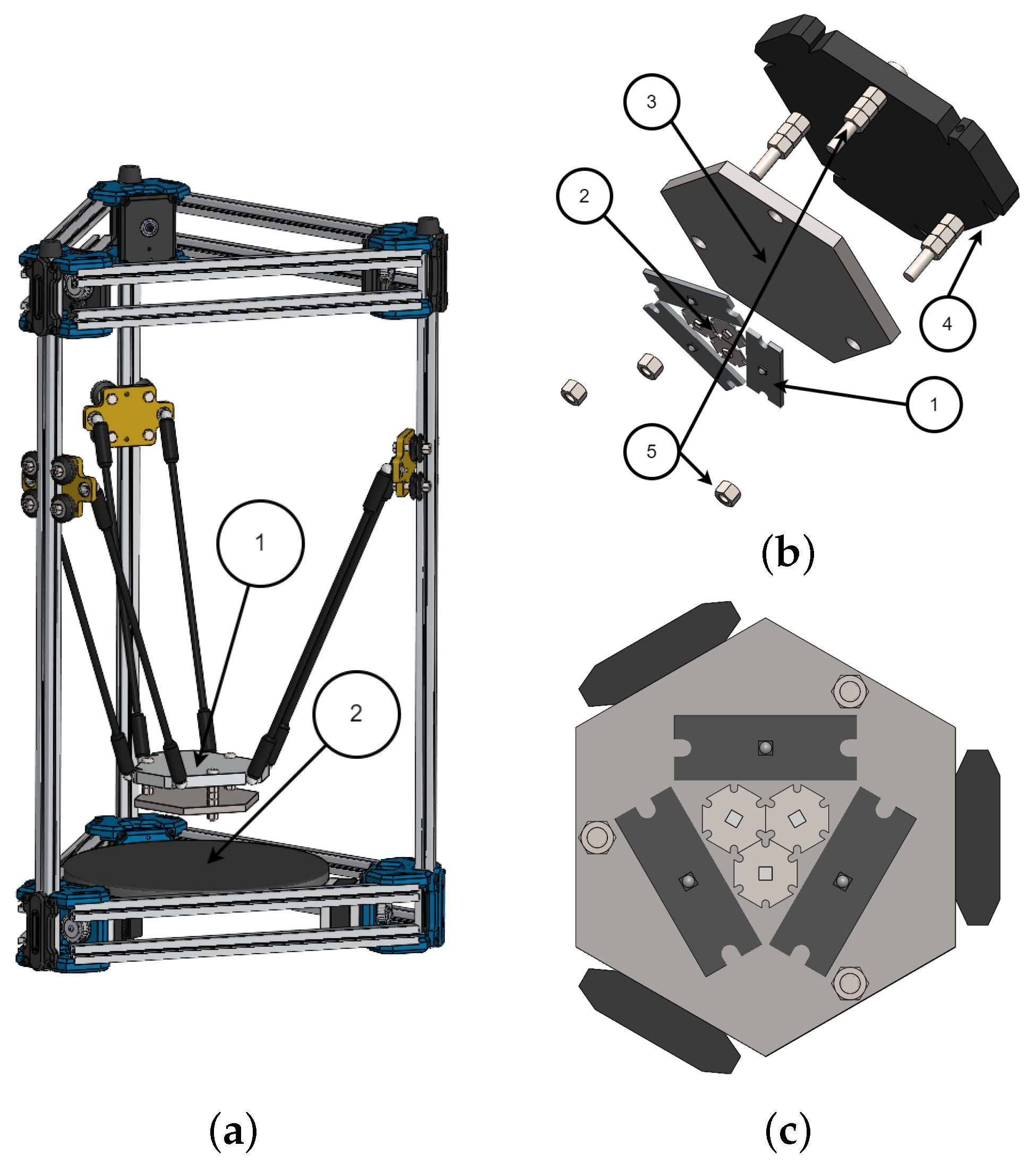
2.3. Delta UV Curing System

The mechanical properties of photopolymerizable solid propellants are closely related to the characteristics of the polymer, the photoinitiator, and the degree of conversion achieved by their mixture when exposed to radiation at a specific wavelength [31,32,33]. In the earlier steps of this research, the reactivity of the propellant to UVA radiation at a wavelength of 375 nm was evaluated [18], revealing significant conversion and improvements in mechanical properties. Lajoie et al. [34] observed enhancements in the mechanical performance of UV-cured solid propellants exposed to various frequencies. Although the previous study by Lajoie et al. did not disclose their specific formulation, the current research pursued a multifrequency analysis based on the absorption characteristics of the photoinitiator used here. In fact, BAPO exhibits two distinct absorption plateaus: one at UVA wavelengths and another in the low-UVB–high-UVC range. For this reason, a UVA-UVC illuminator (Figure 3) was designed to examine the degree of conversion of the dispersion consisting of PB, pentaerythritol tetrakis(3-mercaptopropionate) (PTTM), which is crucial for the thiol–ene reaction, and bis-(2,4,6-trimethylbenzoyl) phenylphosphine oxide (BAPO). The core of the illuminator consists of a hexagonal metal plate, serving as a heat sink, on which three UVA LEDs (Luminus LT-4789, Led-Tech.de, Moers, Germany) and three UVC LEDs (Luminus LT-4783, Led-Tech.de, Moers, Germany) are mounted, with wavelengths of 375 and 285 nm, respectively. These wavelengths were chosen based on a trade-off between the market availability and the absorption spectrum of the photoinitiator, i.e., BAPO, which exhibits two peaks at 288 nm and 371 nm [35,36]. Furthermore, the selected UVA LEDs are identical to those utilized in the final 3D printer prototype. The metal plate is connected to a delta kinematics system (Anycubic Kossel Delta Printer series, Anycubic Technology Co., Ltd., Shenzhen, China) via an additional hexagonal PLA plate.
The movement of the delta mechanism is controlled by three stepper motors located under the print bed, which are connected to a BTT SKR 1.3 board. The LED circuit is segmented into two parallel subcircuits, with each containing LEDs configured in series. The LEDs are turned on and off using two manual switches integrated into the illuminator structure. The circuit is powered at 24 V and integrated with the BED pin outputs of the BTT SKR 1.3 board. The decision to place LEDs of the same category in series was based on the power limits of the board. To ensure safety and prevent exposure to UV radiation, the entire system is enclosed by walls, not depicted in Figure 3a, shielding the eyes of the user. The precise movements achievable with the delta kinematics allowed for the accurate characterization of the illuminator.
On the left side of Figure 4, a MATLAB (R2024a) model illustrates the predicted light intensity distribution in the XY plane at various distances from the transmitters, taking into account the LED positions and reflections on the walls. Using the DeltaOhm HD2102.1 radiometer (Delta OHM, Padua, Italy), the UVA irradiance was measured; the results are presented in Figure 4 on the right. The distances analyzed for UVA ranged from a minimum of 17 to 44.5 mm, with 2.5 mm spacing between the measurement planes. According to their datasheet, the chosen UVC LEDs were expected to have an emission equal to one-tenth of that of UVA.
Following the characterization of the illuminator, a distance was selected to achieve a homogeneous distribution of irradiance across the surface of the sample (with variations below 10%). For UVA, a distance of 34 mm was chosen, resulting in a constant irradiance value of 110 W/m2 over a surface larger than the size of the specimen. For UVC, a distance of 22 mm was selected, resulting in a distribution under one-tenth of that of UVA.

2.4. Cartesian 3D Printer

The rheological and mechanical analyses conducted in this article, as well as in previous work [18,19,20,21], aimed to pave the way for the development of a prototype 3D printer capable of producing scaled propellant samples. The construction of a prototype represents a crucial step towards conducting more accurate and reproducible tests and enhances the Technology Readiness Level. A modular prototype of a 3D printer was designed. This prototype can be modified if some of its components prove to be unsuitable for the propellant printing process, particularly the extruder, which is the most critical part. This section presents the developed 3D printer and the initial printing attempts, detailing the main issues encountered and the solutions implemented, while in Section 4.3 the printing test results will be presented.
The 3D printing process of a photopolymerizable material is divided into three distinct phases. The first phase focuses on the transfer of the slurry from the reservoir to the extruder’s nozzle tip. The subsequent phase involves the precise manipulation of the material on the print bed through the kinematic system. The final phase is the crosslinking process, accomplished via a specialized lighting system. Several approaches have been considered, and a downselection was carried out through an initial trade-off study. Stereolithography systems primarily use illumination from the bottom of a vessel containing non-crosslinked material, while other systems use a bed illuminated from above, where the material on the plane is managed by a spreading blade [37]. These systems appear to be unsuitable for the present purpose because the high viscosity of the material prevents the easy removal of the non-crosslinked material. The option of a coupled deposition bed–resin vat system does not seem feasible in the immediate future due to the complexity of implementation. Moreover, this option complicates the engineering of the illumination setup, as it requires the management of a large surface. The most viable solution appears to be a hybrid printing device that combines elements of stereolithography and Fused Deposition Modeling (FDM). This system employs an extruder to deposit the propellant onto the print bed. Subsequently, each layer is illuminated by an LED blade. This process is repeated for each layer until the desired grain geometry is achieved. The use of a worm screw mechanism to transfer the slurry from the reservoir to the print bed was found to be ineffective due to the separation of the binder and AS powders along its axis. Additionally, the use of such a component could produce significant risks, as the friction of the propellant between the screw and the inner wall of the extruder could cause unintentional ignition. Therefore, a volumetric extrusion system was chosen (Figure 5a), as it preserves the propellant and conveys it to a nozzle that deposits it on the print bed. However, handling the material is complex, as it involves moving a heterogeneous suspension through a pressurized duct. Due to the multiphase nature of the suspension, issues of segregation and separation between the binder and particles may arise. Consequently, the design of the extrusion system’s geometry and the working pressure are critical factors.
The 3D printer (Figure 5b), developed in collaboration with Microdigit, maneuvers a volumetric extruder on a Cartesian axis system. This extruder was developed by modifying the terminal part of a pneumatic piston (SMC CS96-32). The removed piston end section is replaced with a metal plate (also referred to as a nozzle plate), as depicted in Figure 5a. This plate is secured to the piston using four M5 screws. A centrally located threaded hole allows for the attachment of standard nozzles, which are typically used for ceramic 3D printing. Furthermore, as illustrated in Figure 5b, the extruder is equipped with a heating blanket to lower the viscosity by raising the temperature of the slurry.
The movement of the extruder along the three main axes is performed by three NEMA23 stepper motors, which are controlled by an SKR 1.4 Turbo board and a Raspberry Pi running the commercial software Klipper (Version 0.12.0). Due to the high current required by the NEMA motors, incompatible with the standard TMC drivers, it was necessary to use external TB6600 drivers. The thermal blanket of the extruder heating system allows the propellant to be heated up to 100 °C. The temperature is regulated by the PID controller integrated into the Klipper software. Thanks to the Wi-Fi module installed on the SKR board, it is possible to remotely control and monitor the printer.

3. Methodology and Procedures

3.1. Pseudoplasticity Test

For several decades, the pseudoplastic properties of solid propellants have been extensively studied to evaluate their suitability for manufacturing processes. This rheological behavior, characterized by a reduction in viscosity under high shear stress (shear thinning) [38,39,40], is crucial for optimal processing in traditional cast-and-cure manufacturing [40]. In additive manufacturing, it is fundamental not only for slurry preparation but also for defining the printing properties of photocurable propellants. Due to shear-thinning behavior, the application of pressure to the slurry during the printing process reduces its viscosity because of the shear stress exchanged along the extruder walls. Once deposited on the print bed, the viscosity increases in the absence of shear stress, ensuring good adhesion [41,42]. This phenomenon allows for the use of less complex extrusion systems, as it requires less pressure to generate a flow of propellant. Additionally, the values obtained from these tests provide a reference for the pot-life test, which will be described in the following subsection.
The isothermal test bench shown in Figure 1b was used to determine the pseudoplastic behavior of the propellant. The objective of this test was to confirm the preservation of pseudoplastic properties typically observed in traditional propellants. The slurry used to carry out the tests consisted of PB, AS salts, and thiols, avoiding the inclusion of BAPO. In fact, BAPO may cause viscosity variation due to partial unwanted activation even in the absence of UV radiation (e.g., due to heating).
The preparation of the samples involved several steps. After weighing the binder, AS salts, and thiols, the dispersion was manually mixed in a vessel for 5 min to achieve sufficient homogeneity. The resulting compound was gently moved inside the cylindrical PPCF container to avoid excessive compaction. Then, the PPCF vessel was secured above the rectangular support, as illustrated in Figure 1b, and its copper coil was connected to the water pump by means of the blue and red silicone tubes. Finally, the spindle was slowly lowered into the compound to ensure proper positioning.
The investigations were carried out using the standard LV4 rotor. The selected speeds fell within the range of 0.6 to 3 RPM. The temperature setpoints were fixed at 60 °C and 80 °C, with oscillations confined within a margin of ±1.5 °C. These temperatures were chosen based on the range investigated in Ref. [20] for viscosity reduction and on the most stringent thermal operational limits of the final 3D printer components. The average test duration was three hours for each rotational velocity.

3.2. Pot-Life Test

The pot-life is an important parameter that indicates the amount of time the slurry remains fluid after mixing, including the curing agents [43]. This timeframe is governed by the polymerization process, which leads to an increase in viscosity. This rheological behavior renders the propellant unusable once a specific viscosity threshold is exceeded. In the proposed process, the slurry temperature is raised to reduce the viscosity and improve extrusion. Unfortunately, maintaining the slurry at elevated temperatures initiates a precuring process, even without ultraviolet radiation. Therefore, it was crucial to assess how the viscosity changed over time at a specific temperature after the addition of the photoinitiator, i.e., BAPO.
The sample preparation followed the same procedure described in the preceding paragraph for the pseudoplastic tests, with the only difference being the addition of BAPO. The pot-life analysis was performed using a standard LV4 rotor, as the viscosities were close to the instrument’s measurable limits. The chosen rotor speed was 0.6 RPM for comparative analysis with the viscosity obtained in the pseudoplasticity tests. The temperature setpoint was maintained at 60 °C and 80 °C in separate tests, each using a new propellant. Temperature fluctuations were kept within a margin of ±1.5 °C. In addition, a perforated cap was employed to provide access to the rotor and thermometers, ensuring adequate protection against potential external light sources that might cause partial polymerization. The adopted method clearly mitigates most of the potential influence of light on the rheological properties of the propellant, allowing the evaluated pot-life to be attributed solely to the thermal state of the sample.

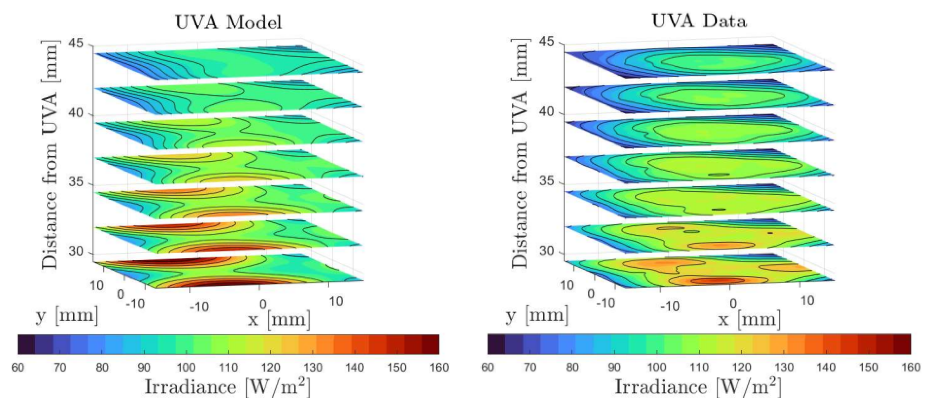
3.3. Uva and UVC Curing Test

The mechanical properties of solid propellant grains are critical for ensuring proper rocket engine operation. Failure to meet the required minimum values can cause various problems, such as crack formation, which locally increase the burning area, leading to a possible deflagration-to-detonation transition [44]. The mechanical properties of composite solid propellants are influenced by the degree of crosslinking of the binder and the interactions between the binder and oxidizer particles. To enhance these properties, bonding agents can improve the adhesion between the resin and oxidizer particles, while other methods can be employed to increase the crosslinking of polymers, which is directly related to the mechanical characteristics of the binder [32,40]. One purpose of the present work was to optimize the degree of polymerization of the PB by determining the binder’s response not only to UVA, as has already been studied in previous work [19], but also to a combination of UVA and UVC, as suggested by previous research studies [34]. UVC LEDs are known for their significantly lower efficiency compared to UVA, which results in greater heat dissipation. This increased heat can reduce the operational lifespan of devices and necessitates an adequate cooling system. Consequently, the power transmitted to the propellant is low when compared to the input power [45]. However, these drawbacks may be offset by the higher absorbance of BAPO in the UVC range. Additionally, UVC can penetrate deeper into the propellant, aiding the curing of thicker layers.
To evaluate the binder’s degree of polymerization, the swelling test method was performed according to the ASTM-D2765 standard [46]. Sample preparation began by manually mixing PB, thiols, and the BAPO in a beaker for 5 min. The resulting dispersion was then poured into a rectangular silicone mold with 1 cm sides. To obtain specimens with the desired thickness, the density of the dispersion was evaluated based on the values provided in the Sigma-Aldrich datasheets. Since the surface area of the specimen remained consistently 1 cm2, the required volume could be based solely on the thickness. Each sample was weighed using a precision balance to ensure compliance with the requirements, minimizing deviation. Subsequently, the silicone mold containing the dispersion was placed under the UV LED and illuminated for specified times. Afterwards, the cured specimen was extracted from the silicone mold and placed inside a container, into which toluene was poured to perform the swelling test. Due to the toxicity of toluene, this phase and the subsequent ones were carried out under a chemical hood.
The swelling test involved three phases: first, the measurement of the mass, m 1 , of the sample before immersing it in toluene; second, immersing the specimen for approximately 20 h and then weighing it immediately after extraction to determine its mass, m 2 ; and third, the measurement of the mass, m 3 , of the sample three days after extraction. The swelling factor (SF), required to determine the polymer’s ability to absorb the solvent, was evaluated as
S F = m 2 m 1
while the Polymer Conversion Percentage (PCP) was evaluated as
P C P = m 3 m 1 · 100
The principle underlying swelling tests is relatively simple. This method involves immersing the hardened sample in toluene, which induces swelling. The process causes the long and entangled polybutadiene polymer chains to expand into a larger volume, facilitating the escape of PB monomers from the specimen. Consequently, at the conclusion of the second phase, the sample will consist exclusively of the PB chains that have successfully bonded together, along with the toluene absorbed during immersion. Weighing the sample three days after extraction allows for the complete evaporation of the toluene, enabling the measurement of the weight of the polymerized chains alone. By comparing this weight to the initial total weight of the specimen, the degree of polymer conversion can be determined. The specimens are shown in Figure 6.
Different exposure times, sample layer thicknesses, and slurry temperatures were considered. A test matrix and the corresponding measured PCP (Polymer Conversion Percentage) will be presented in Section 4.

4. Results

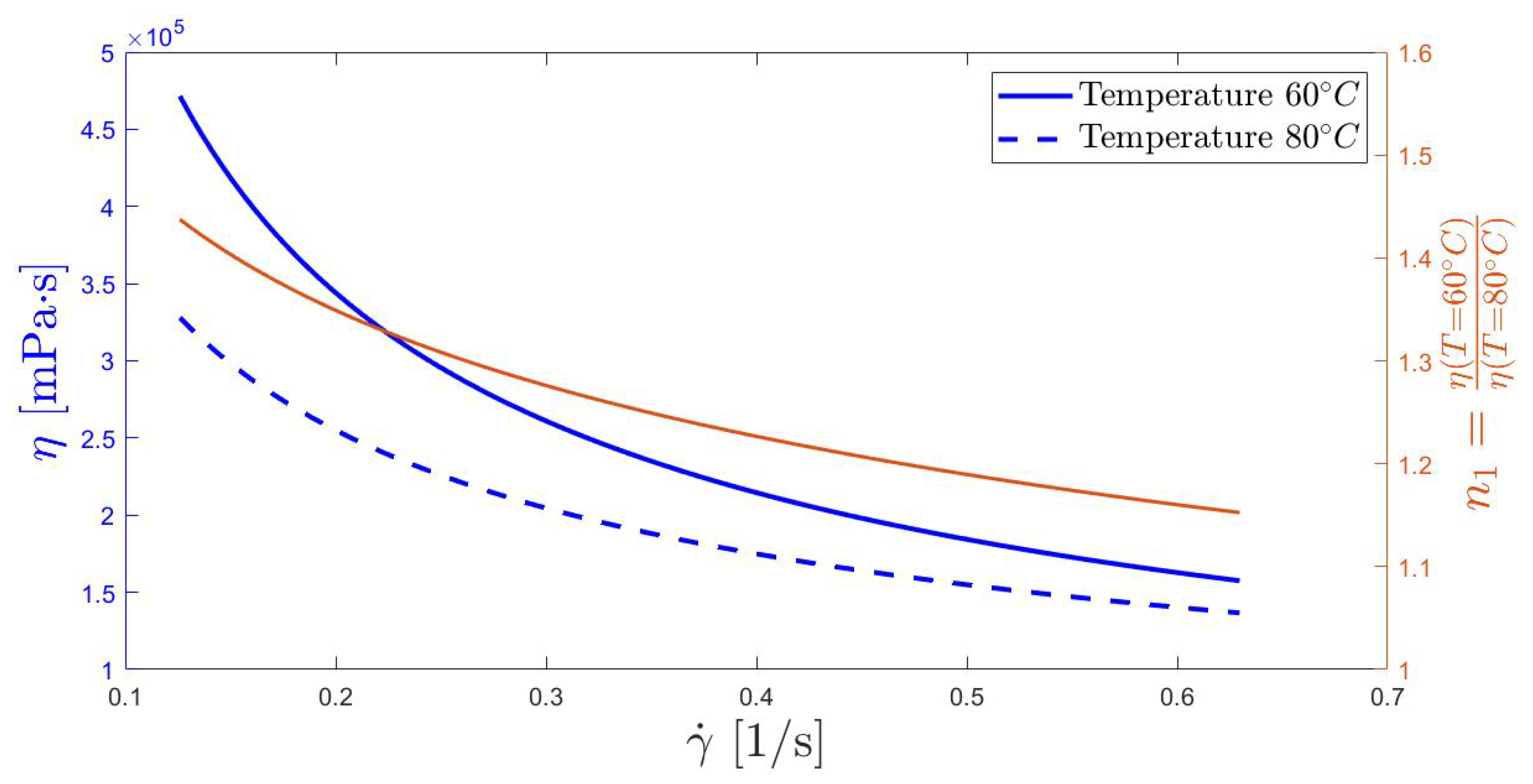
4.1. Pseudoplasticity Test
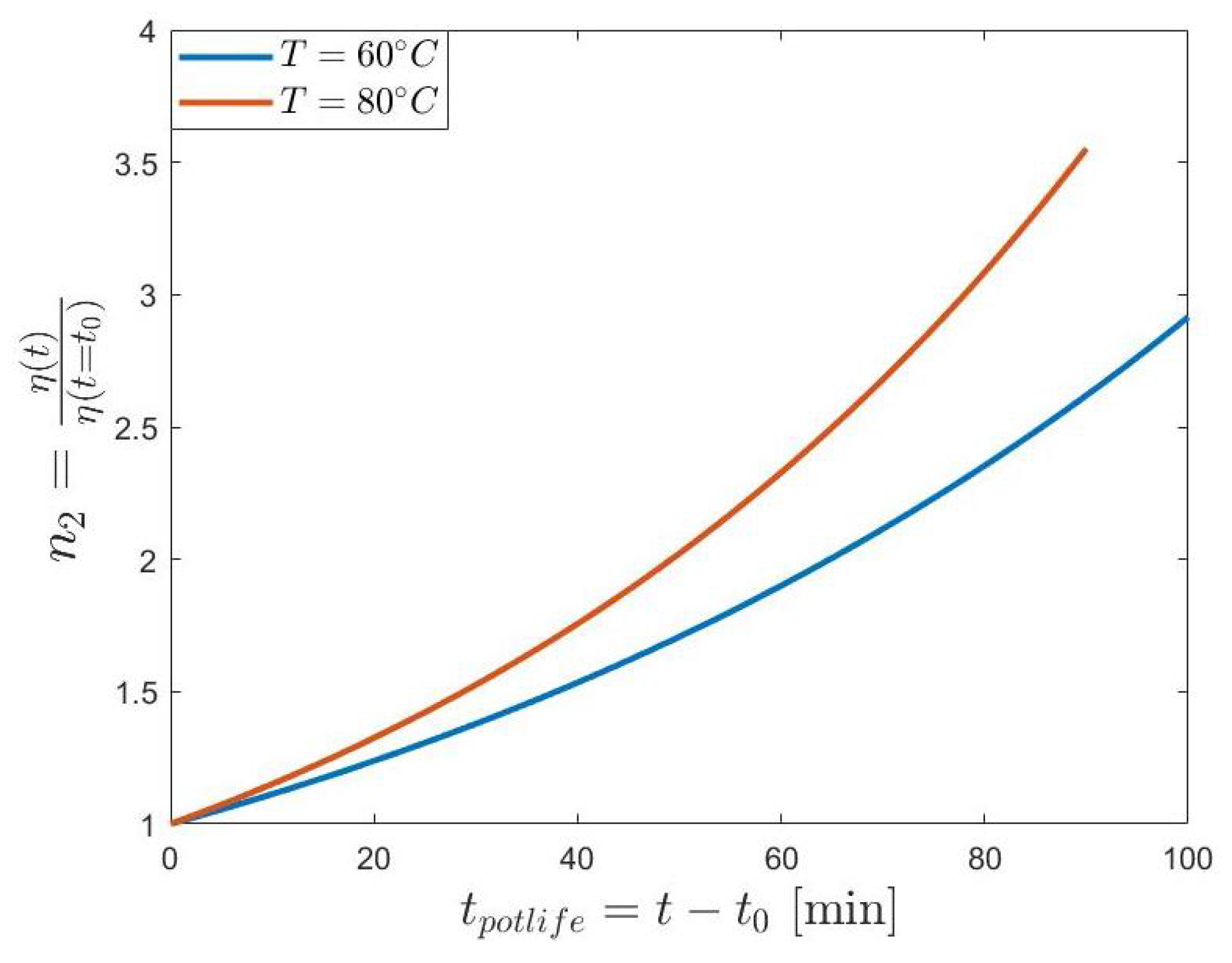
Figure 7 illustrates the results, depicted with the blue lines, obtained by varying the applied shear stress on the propellant while maintaining constant temperatures of 60 ± 1.5 °C and 80 ± 1.5 °C.
The graph is represented as a function of the shear rate ( γ ˙ ), obtained by multiplying the spindle rotation speed ( ω s ) by the large cylinder gap geometric factor reported by Mezger [25]. The pseudoplastic behavior followed the Ostwald–de Waele model. This law associates the shear stress ( τ ) with the shear rate ( γ ˙ ) through the following relationship:
τ = K γ ˙ n
The curves were interpolated using the equation
η = τ γ ˙ = K γ ˙ n 1
where K is the consistency index in [Pa n ], and n is the flow index. The consistency index is a specific constant of the analyzed fluid, while the flow index describes how the viscosity changes in response to shear stress. When n = 1 , the fluid behaves like a Newtonian fluid (K = η ). If n < 1 , the fluid exhibits pseudoplastic behavior, and if n > 1 , it shows dilatant behavior [25]. The R2 values for the fits at 60 °C and 80 °C were R 2 = 0.977 and R 2 = 0.987 , respectively.
As the temperature increased, the pseudoplastic properties of the propellant decreased, resulting in a less pronounced reduction in viscosity with increasing shear stress. This phenomenon is illustrated by the red line in Figure 7, which represents the ratio between the two blue lines. The n 1 parameter was consistently greater than one, indicating that it is always advantageous to increase the temperature. However, as will be discussed in the following paragraph, the pot-life imposes a limit on the slurry temperature. Therefore, a trade-off between these two rheological characteristics is needed to optimize the print quality. This aspect is extremely important when determining the printing speed and, consequently, the shear stress to which the propellant is subjected. The advantage of a temperature increase is demonstrated in other studies in the literature [11].
The analysis was constrained by the small number of selectable rotor speeds. Nevertheless, the speeds used during the measurements fell within the appropriate range for qualitatively describing the pseudoplastic behavior of photocurable propellants [25]. The viscosity results are summarized in Table 1. The standard deviation (SD%) of the viscosity was affected by temperature fluctuations, which were present despite the use of a PID controller. These fluctuations contributed to the variability of the measurements. It can be concluded that the mean value of the samples provides an adequate approximation of the propellant viscosity at temperatures close to 60 °C and 80 °C, respectively.
The calculated flow index n was 0.32 at 60 °C and 0.46 at 80 °C. These values differ from those reported in the literature [9,10,11], which presents values between 0.5 and 0.7, suggesting less pronounced shear-thinning behavior. This discrepancy can be attributed to the significant sensitivity of the propellant’s rheological behavior to the size and proportion of oxidant powders, as well as the presence of thiols in this specific instance. The selected particle sizes of ammonium sulfate played a crucial role in this effect. Specifically, a diameter ratio below 0.155 allowed the fine particles to move more freely among the larger particles, thereby reducing the propellant’s viscosity. Consequently, an enhancement in the pseudoplastic properties was observed, indicated by a decreasing value of the n index [8].

4.2. Pot-Life Test

Figure 8 shows n 2 , i.e., the viscosity normalized with respect to the value measured at the end of the PID transient ( t 0 ), i.e.,
n 2 = η ( t ) η ( t 0 )
The numerator in RHS of Equation 6 represents the viscosity measured by the viscometer as a function of time and the denominator the viscosity measured at t 0 . The tests, carried out at 60 °C and 80 °C with a spindle rotor speed equal to 0.6 RPM, were interrupted upon reaching the viscometer’s upper limit, which was 10 6 cP (mPa·s). The time t 0 needed to reach the chosen temperature was found to be 30 min for the 60 °C case and 45 min for the 80 °C case. Anyway, it was observed that at t 0 the viscosity of the slurry was comparable to the reference value shown in Table 1. The normalized viscosity n 2 showed a more pronounced increase in viscosity at 80 °C, compared to the case at 60 °C. This implies that the time range during which the propellant remains printable decreases as the printing temperature increases. Consequently, it is necessary to determine a compromise temperature, considering the maximum viscosity threshold that the extruder is capable of managing and the printing time.
As can be observed in Figure 8, the initial hypothesis that BAPO reacts undesirably to heat was confirmed, highlighting the necessity of establishing printing time limits. In the printer prototype, a volumetric extruder system which holds a limited amount of material is used. Therefore, the required minimum pot-life is reduced to a dimensional factor based on the printing speed that defines the printable volume within a specified time limit. On the contrary, the use of a tank connected via a tube to the extruder would significantly increase the needed extrusion pressure, causing the separation of the liquid component of the propellant from the solid one. Therefore, the use of a refillable syringe system, sized according to the printing time allowed by the pot-life, can be considered for future printer prototypes.

4.3. Uva and UVC Curing Tests

Table 2 shows the series of tests carried out to analyze the response of the photocurable propellant to different UV light frequencies. These tests were performed using the delta UV curing system described in Section 2.3.
The first section of Table 2 presents the results of tests conducted using only UVA LEDs for a layer of about 1 mm and different exposure times. These serve as a reference, demonstrating that increasing the UVA exposure time leads to higher PCP values. The second section examines samples exposed for a total time of 270 s, with three combinations of UVA and UVC times. The results suggest that the PCP is primarily driven by UVA radiation, while longer UVC exposure does not provide additional benefits. In the third section, the results are shown for different UVA exposure times tested while keeping the UVC exposure constant at 180 s. The PCPs obtained were comparable to those obtained with UVA alone, indicating that the tested UVC LEDs were not useful even as a postcuring process, as occurs in industrial stereolithography [37].
For samples of a 1 mm layer height, multifrequency tests for fixed UVC exposure (180s) combined with a varying UVA exposure duration (90 s, 180 s, 270 s) consistently showed a p-value ≤ 0.001, indicating with strong statistical significance that the PCP increases with longer UVA exposure. When comparing monofrequency-cured samples (UVA only, as shown in the first section of Table 2: 90 s, ‘low-cured’; 180 s, ‘mid-cured’; 270 s, ‘high-cured’) to their multifrequency counterparts (same UVA exposure duration plus 180 s of UVC), the trend was less distinct. Specifically, reference series for ‘low-cured’ and ‘high-cured’ samples exhibited a p-value ≤ 0.05, i.e., the addition of UVC had moderate statistical signifance. On the other hand, the ‘mid-cured’ samples displayed a p-value ≈ 0.30, necessitating further testing to be conducted in the future.
The fourth and fifth sections show the results from the analysis of thicker layers (2 mm and 3 mm) while maintaining a total exposure time of 270 s. Since UVC wavelengths are shorter, they were hypothesized to penetrate deeper into the resin and aid in curing thicker layers. However, the results, though only preliminary, contradict this assumption. For samples cured only with UVA, the PCP difference between 2 mm (91.6%) and 3 mm (89.7%) was minimal. In contrast, when using 180 s UVA + 90s UVC, the PCP dropped significantly from 91.6% (2 mm) to 80.7% (3 mm), indicating that UVC does not improve deeper-layer curing These findings suggest that the selected UVC LEDs, in combination with the photoinitiator system of PB, BAPO, and PPTM (identified as highly effective across a broad spectrum of resins [19]), do not offer any advantages in the current formulation.
Finally, the last section examines the impact of preheating at 90 °C. The reduction in the PCP for the preheated samples aligns with the degradation of tensile mechanical properties reported in [20]. As shown in Table 2, this PCP reduction can be adequately mitigated by extending the exposure time. Additionally, the PCP can be finely adjusted to enhance interlayer adhesion in 3D printing applications. Further investigations, including swelling tests and microtomography, will be conducted to refine the current analysis.

4.4. 3d Printing Test

The prototype described in Section 2.4 was used to carry out a series of tests. The initial step that must be undertaken before printing is calibration. If this process is performed incorrectly, it is impossible to achieve a successful print [47]. The calibration process was particularly complex due to the binder’s elasticity, which induced a non-linear response of the flow rate to the applied piston force and resulted in an unwanted extrusion through the nozzle at the end of each layer. The first issue caused a delay in the deposition of the material, which was addressed through a precompression of the propellant before each print. Regarding the second issue, a retraction mechanism was initially employed; however, it proved ineffective as it also eliminated the precompression, thereby reintroducing the first problem. Consequently, a shutter capable of mechanically blocking the flow was used. Preliminary printing tests performed with a shutter highlighted the interference between the printed part and the shutter blade. Therefore, a redesign was planned referring to the style of shutter valve-based extruder presented in [48].
After the initial calibration phase, preliminary printing tests were performed on simple single-layer and multilayer specimens, varying the geometric parameters of the extruder. It was observed that utilizing nozzles with a smaller output diameter increased both the precision and extrusion pressure, which in severe cases led to the separation of the solid component from its liquid counterpart. The remaining slurry in the extruder chamber after the printing process, shown in Figure 9, exhibited the separation of the solid phase of the slurry during extrusion. This phenomenon arose from the pressure necessary to move a high-viscosity biphasic material such as the slurry, resulting in the accumulation of AS powder within the extruder and the outflow of a high-PB-concentration slurry. To address this issue, limitations were primarily imposed on the nozzle geometry, printing speed, and slurry temperature.
The main variables to consider in the design of the extruder are the following [49,50]:
  • Viscosity: An increase in its value results in a non-linear reduction in the extrudable flow rate. The increase in temperature must be carefully evaluated to achieve a reduction in the viscosity of the slurry without drastically compromising the mechanical properties.
  • Nozzle diameter: An excessive value makes it impossible to form objects with a defined shape, while an insufficient value leads to nozzle clogging. The average flow velocity in relation to the nozzle diameter shows a complex trend in the case of biphasic materials such as solid propellants.
  • To estimate the volumetric flow of the propellant, a simplified model can be used, which assumes a constant fluid density during the extrusion process, a steady flow within the nozzle, and that the nozzle exit diameter is significantly smaller than the syringe diameter. According to these assumptions, the pressure difference in the nozzle is defined by
    Δ p = p p e x t
    where (p) is the pressure applied by the syringe piston, while ( p e x t ) is the ambient pressure. If the slurry exhibits behavior describable by Equation (4), the theoretical flow rate can be obtained by [51]
    Q t = π D i 3 D 0 3 32 3 n Δ p tan ( θ 0 ) 2 K ( D i 3 n D 0 3 n ) 1 n
    where ( θ 0 ), ( D i ), ( D o ), and ( L t ) represent the characteristic angle of the extruder nozzle, the inner inlet diameter of the nozzle, the outlet diameter, and the length between the two sections, respectively. Assuming a constant volumetric flow rate based on the design printing speeds, to reduce ( Δ p ), it is necessary to increase the geometry of the nozzle’s outlet diameter or reduce the viscosity by increasing the temperature (reducing the K factor) or vary the nozzle angle ( θ 0 ). Consequently, three standard nozzles were used, 0.6 mm, 1.5 mm, and 3 mm, respectively, with an angle, ( θ 0 ), of 60°, applying preheating up to 80 °C.
As shown in Figure 10a, it was possible to produce a homogeneous propellant layer using 1.5 and 3 mm nozzles at a temperature of approximately 70 °C and multiple layers (Figure 10b). A progressive deterioration in the print quality was observed over the months of testing, resulting in the condition shown in Figure 10c. It was found that the cause was the absorption of water by AS, which is a hygroscopic salt. The storage method used for AS salts was found to be inadequate, underscoring the necessity of maintaining low moisture absorption levels before the printing process. It is important to note that the printing tests were conducted over a period of six months, and during the first two months, no significant changes were observed in the printing process. Therefore, this aspect does not pose a problem if the salts are produced shortly before the printing process.

5. Conclusions

This study provides a comprehensive evaluation of UV-curable solid rocket propellants designed for advanced additive manufacturing by means of the measurements of propellant properties and 3D printing tests carried out with a properly designed modular printer. The findings confirm that the propellants exhibit pseudoplastic behavior, which facilitates smoother extrusion during 3D printing. Although increasing the temperature effectively reduces the viscosity, it also shortens the propellant’s pot-life, necessitating a careful balance between the print speed and thermal management. Based on the pot-life tests, the equilibrium temperature range for the optimal printability and pot-life should be between 60 °C and 70 °C. This range allows for a balance between reduced viscosity for easier extrusion and a manageable pot-life to ensure the material remains printable for a sufficient duration. Implementing a dynamic temperature control strategy that adjusts the temperature in real time based on the extrusion rate and viscosity measurements may help maintain the equilibrium temperature within the optimal range, enhancing the overall print quality and consistency. UV photopolymerization, particularly with UVA radiation, proved effective in curing the propellant and enhancing its mechanical properties. The preliminary results suggest that, under the tested conditions, UVC exposure did not significantly improve the polymer conversion rate and introduced additional challenges, such as heat dissipation and lower energy efficiency. However, given the potential of shorter wavelengths to influence curing at a microstructural level, further investigations—such as microtomography studies—will be conducted to explore the role of UVC in greater detail. For now, UVA irradiation remains the most reliable method for optimizing curing in this specific formulation. The 3D printing trials identified technical challenges, such as material segregation within the extruder, highlighting the need for the further refinement of the extrusion system. To address these challenges, several technological improvements were proposed. Nozzle optimization, by utilizing nozzles with varying diameters (0.6 mm, 1.5 mm, and 3 mm), can help optimize the flow rate and reduce clogging. Smaller nozzles increase precision but may require higher extrusion pressures, while larger nozzles reduce the pressure but may affect the detail of the print. Implementing a redesigned shutter mechanism based on successful designs from the existing literature, such as the shutter valve-based extruder, can help control the flow of material and prevent unwanted extrusion at the end of each layer. Additionally, the moisture sensitivity of the propellant emerged as a significant issue affecting the print quality. Overall, these findings contribute to the ongoing development of UV-curable propellants for additive manufacturing, offering valuable insights into improving curing strategies, the printability, and the material performance. By addressing current limitations and exploring advanced characterization techniques, this research helps to advance the technology toward higher readiness levels, paving the way for its broader application in composite solid propellant manufacturing.

Author Contributions

Conceptualization, F.M., G.T., A.Z., G.P., L.S., A.F. and D.P.; data curation, G.T.; funding acquisition, D.P.; investigation, G.T., A.Z. and C.N.; methodology, F.M., G.T. and A.Z.; project administration, F.M. and D.P.; software, G.T.; supervision, F.M., A.Z., C.N., A.F. and D.P.; visualization, G.T. and A.Z.; writing—original draft, G.T. and A.Z.; writing—review and editing, F.M., A.Z. and D.P. All authors have read and agreed to the published version of the manuscript.

Funding

This research was supported by Fondazione Compagnia di San Paolo (PoC Transition, cut-off I, 2022–2024).

Institutional Review Board Statement

Not applicable.

Informed Consent Statement

Not applicable.

Data Availability Statement

The data are contained within the article.

Acknowledgments

We acknowledge the SpLab of Politecnico di Milano for processing and delivering ammonium sulfate in the required diameters. Furthermore, we want to acknowledge the PST team’s laboratory (DISAT) for the continuous support in conducting swelling tests in a safe environment.

Conflicts of Interest

The authors declare no conflicts of interest.

Abbreviations

The following abbreviations are used in this manuscript:
APAmmonium perchlorate
ASAmmonium sulfate
BAPOBis-(2,4,6-trimethylbenzoyl) phenylphosphine oxide
FDMFused Deposition Modeling
HTPBHydroxyl-Terminated Polybutadiene
PBPolybutadiene
PIDProportional–Integral–Derivative controller
PLAPolylactic acid
PPCFPolypropylene-reinforced carbon fiber
PTTMPentaerythritol tetrakis(3-mercaptopropionate)
PCPPolymer Conversion Percentage
RPMRevolutions per minute
SDStandard deviation
SFSwelling factor
UVUltraviolet radiation

Mathematical and Experimental Variables

AArea, mm2
D i Extruder nozzle inlet diameter, m
D o Extruder nozzle outlet diameter, m
FApplied force, N
KFlow consistency index, Pa n
L 0 Gauge length, m
L t Outlet diameter, m
lnNatural logarithm
nFlow behavior index
n 1 Ratio between 60 °C and 80 °C for pseudoplastic curves
n 2 Adimensional viscosity in pot-life test
pPressure, Pa
p e x t Ambient pressure
Q t Volumetric flow of propellant, m3/s
R 2 Coefficient of determination
TTemperature, °C or K
t 0 Time for PID transient to reach temperature
τ Shear stress, Pa
θ 0 Extruder nozzle angle, rad
γ ˙ Shear rate, 1/s
η Viscosity, Pa·s
Φ Diameter, cm
ω s Rotor speed, [1/s]

References

  1. Barrère, M. Rocket Propulsion; Elsevier: Amsterdam, The Netherlands, 1960. [Google Scholar]
  2. Miller, W.H. Solid Rocket Motor Performance Analysis and Prediction; Technical Report NASA SP-8039; National Aeronautics and Space Administration: Washington, DC, USA, 1971.
  3. Sutton, G.P.; Biblarz, O. Rocket Propulsion Elements; John Wiley & Sons: Hoboken, NJ, USA, 2016. [Google Scholar]
  4. McClain, M.S.; Afriat, A.; Rhoads, J.F.; Gunduz, I.E.; Son, S.F. Development and characterization of a photopolymeric binder for additively manufactured composite solid propellant using vibration assisted printing. Propellants Explos. Pyrotech. 2020, 45, 853–863. [Google Scholar] [CrossRef]
  5. Bogue, R. 3D printing: The dawn of a new era in manufacturing? Assem. Autom. 2013, 33, 307–311. [Google Scholar] [CrossRef]
  6. Joshi, S.C.; Sheikh, A.A. 3D printing in aerospace and its long-term sustainability. Virtual Phys. Prototyp. 2015, 10, 175–185. [Google Scholar] [CrossRef]
  7. Song, S.; Shi, J.; Ren, Q.; Miao, K.; Tang, M.; Shi, H. Comparative Study on Extrusion 3D Printing of Solid Propellant Based on Plunger and Screw. Materials 2025, 18, 777. [Google Scholar] [CrossRef]
  8. Muthiah, R.; Krishnamurthy, V.; Gupta, B. Rheology of HTPB propellant. I. Effect of solid loading, oxidizer particle size, and aluminum content. J. Appl. Polym. Sci. 1992, 44, 2043–2052. [Google Scholar] [CrossRef]
  9. Osgood, A. Rheological characterization of non-Newtonian propellants for casting optimization. In 5th Propulsion Joint Specialist; AIAA: Reston, VA, USA, 1969; p. 518. [Google Scholar]
  10. Mahanta, A.; Dharmsaktu, I.; Pattnayak, P. Rheological behaviour of HTPB-based composite propellant: Effect of temperature and pot life on casting rate. Def. Sci. J. 2007, 57, 435–442. [Google Scholar] [CrossRef]
  11. Mahanta Abhay, K.; Monika, G.; Pathak Devendra, D. Empirical modeling of chemoviscosity of hydroxy terminated polybutadiene based solid composite propellant slurry. Malays. Polym. J. 2010, 5, 1–16. [Google Scholar]
  12. McClain, M.; Gunduz, I.; Son, S. Additive manufacturing of ammonium perchlorate composite propellant with high solids loadings. Proc. Combust. Inst. 2019, 37, 3135–3142. [Google Scholar] [CrossRef]
  13. McClain, M.; Afriat, A.; Montano, B.J.; Ray, S.; Rhoads, J.; Gunduz, I.E.; Son, S.F. Investigation of Additively Manufactured Layered Composite Solid Propellant. In Proceedings of the AIAA Scitech 2020 Forum, Orlando, FL, USA, 6–10 January 2020. AIAA Paper 2020-1427. [Google Scholar] [CrossRef]
  14. McClain, M. Additive Manufacturing of Viscous Materials: Development and Characterization of 3d Printed Energetic Structures. Ph.D. Thesis, Purdue University, Wlest Lafayette, IN, USA, 2020. [Google Scholar] [CrossRef]
  15. Plotzke, J.; Torgerson, N.R.; Seaberg, S.D.; McClain, M. Mechanical Properties of 3D-Printed Multi-Material Polymeric Composites. In Proceedings of the AIAA SCITECH 2024 Forum, Orlando, FL, USA, 8–12 January 2024. [Google Scholar] [CrossRef]
  16. Tkachev, D.; Dubkova, Y.; Zhukov, A.; Verkhoshanskiy, Y.; Vorozhtsov, A.; Zhukov, I. Photocurable high-energy polymer-based materials for 3d printing. Polymers 2023, 15, 4252. [Google Scholar] [CrossRef]
  17. Tan, B.; Dou, J.; Wen, Y.; Duan, B.; Mo, H.; Wei, Z.; Zhang, J.; Pan, Y.; Ding, X.; Liu, N. 3D printing for explosive and propellant applications. Addit. Manuf. Front. 2024, 3, 200151. [Google Scholar] [CrossRef]
  18. Garino, S.; Antonaci, P.; Pastrone, D.; Sangermano, M.; Maggi, F. Photo-polymerization for additive manufacturing of composite solid propellants. Acta Astronaut. 2021, 182, 58–65. [Google Scholar] [CrossRef]
  19. Galavotti, A.; Noè, C.; Polizzi, G.; Antonaci, P.; Maggi, F.; Masseni, F.; Pastrone, D. Solid Rocket Propellant Photo-Polymerization with an In-House LED-UV Prototype. Polymers 2023, 15, 1633. [Google Scholar] [CrossRef] [PubMed]
  20. Zumbo, A.; Stumpo, L.; Antonaci, P.; Ferrero, A.; Masseni, F.; Polizzi, G.; Tetti, G.; Pastrone, D. Rheological and Mechanical Characterization of 3D-Printable Solid Propellant Slurry. Polymers 2024, 16, 576. [Google Scholar] [CrossRef] [PubMed]
  21. Masseni, F.; Zumbo, A.; Stumpo, L.; Polizzi, G.; Tetti, G.; Lusetti, T.; Noé, C.; Antonaci, P.; Ferrero, A.; Pastrone, D.; et al. Advancements in Photocurable Solid Propellants for Additive Manufacturing. In Proceedings of the AIAA SCITECH 2025 Forum, Orlando, FL, USA, 6–10 January 2025. [Google Scholar] [CrossRef]
  22. Bisbee, W.; Flanagan, J.; Grant, L.; Hamermesh, C.; Hilzinger, J.; Fujikawa, C.; Lawton, E.; Beck, C. Study to Find Simulants for Fuels for Use in Structures Fatigue Testing; Technical Report ASD-TRD-63-405; Air Force Flight Dynamics Laboratory, Research and Technology Division, Air Force Systems Command: Air Force Base, OH, USA, 1963. [Google Scholar]
  23. Sohn, H.; Moreland, C. The effect of particle size distribution on packing density. Can. J. Chem. Eng. 1968, 46, 162–167. [Google Scholar] [CrossRef]
  24. Esiyok, H.; Candarli, M.E. Theoretical and Experimental Packing Density Study of Hydroxyl Terminated Polybutadiene-Ammonium Perchlorate Based Propellant and Its Influence on Burning Rate. Int. J. Energetic Mater. Chem. Propuls. 2014, 13, 455–469. [Google Scholar] [CrossRef]
  25. Mezger, T.G. The Rheology Handbook; Vincentz Network: Hannover, Germany, 2012; Volume 10. [Google Scholar] [CrossRef]
  26. Mischenko, S.; Mordasov, M.; Savenkov, A.; Sychev, V. Analysis of the influence of sizes of a vessel with a liquid on the readings of Brookfield viscometer. Meas. Tech. 2020, 63, 288–294. [Google Scholar] [CrossRef]
  27. SAMA Tools. SAVISC152-2, 2010.
  28. ISO 2555; Plastics—Resins in the Liquid State or as Emulsions or Dispersions—Determination of Apparent Viscosity Using a Single Cylinder Type Rotational Viscometer Method. International Organization for Standardization: Geneva, Switzerland, 2018. Available online: https://www.iso.org/standard/70023.html (accessed on 5 March 2025).
  29. ASTM D1084-B; Standard Test Methods for Viscosity of Adhesives. ASTM International: West Conshohocken, PA, USA, 2021. Available online: https://www.astm.org/d1084-16r21.html (accessed on 5 March 2025).
  30. ASTM D2196; Standard Test Methods for Rheological Properties of Non-Newtonian Materials by Rotational Viscometer. ASTM International: West Conshohocken, PA, USA, 2020. Available online: https://www.astm.org/d2196-20.html (accessed on 5 March 2025).
  31. Aznarte, E.; Ayranci, C.; Qureshi, A. Digital light processing (DLP): Anisotropic tensile considerations. In Proceedings of the Solid Freeform Fabrication Symposium, Austin, TX, USA, 7–9 August 2017. [Google Scholar]
  32. Saed, A.; Behravesh, A.; Hasannia, S.; Ardebili, S.; Akhoundi, B.; Pourghayoumi, M. Functionalized poly l-lactic acid synthesis and optimization of process parameters for 3D printing of porous scaffolds via digital light processing (DLP) method. J. Manuf. Process. 2020, 56, 550–561. [Google Scholar] [CrossRef]
  33. Nielsen, L.E. Cross-linking–effect on physical properties of polymers. J. Macromol. Sci. Part 1969, 3, 69–103. [Google Scholar] [CrossRef]
  34. Lajoie, J.; Blocker, J.; Sippel, T. Rheological, Ballistic and Mechanical Properties of 3D Printed, Photocured Composite Propellants. J. Propuls. Power 2023, 39, 1–9. [Google Scholar] [CrossRef]
  35. Zhou, H.; Huang, Y.; Zhang, Y.; Song, D.; Huang, H.; Zhong, C.; Ye, G. Hydrogen abstraction of carbon/phosphorus-containing radicals in photoassisted polymerization. RSC Adv. 2016, 6, 68952–68959. [Google Scholar] [CrossRef]
  36. Stiles, A.; Tison, T.A.; Pruitt, L.; Vaidya, U. Photoinitiator selection and concentration in photopolymer formulations towards large-format additive manufacturing. Polymers 2022, 14, 2708. [Google Scholar] [CrossRef] [PubMed]
  37. Huang, J.; Qin, Q.; Wang, J. A review of stereolithography: Processes and systems. Processes 2020, 8, 1138. [Google Scholar] [CrossRef]
  38. Sakovich, G. Design principles of advanced solid propellants. J. Propuls. Power 1995, 11, 830–837. [Google Scholar] [CrossRef]
  39. Wang, H.; Ji, Y.; Jiang, X.; Li, Z. Study on Rheological Properties and Pouring Process of Hydroxyl-Terminated Polybutadiene (HTPB) Propellants. Polymers 2023, 15, 4707. [Google Scholar] [CrossRef]
  40. Singh, H.; Shekhar, H. Solid Rocket Propellants: Science and Technology Challenges; Royal Society of Chemistry: London, UK, 2016. [Google Scholar]
  41. Herrada-Manchón, H.; Fernández, M.A.; Aguilar, E. Essential Guide to Hydrogel Rheology in Extrusion 3D Printing: How to Measure It and Why It Matters? Gels 2023, 9, 517. [Google Scholar] [CrossRef]
  42. Chen, N.; He, C.; Pang, S. Additive manufacturing of energetic materials: Tailoring energetic performance via printing. J. Mater. Sci. Technol. 2022, 127, 29–47. [Google Scholar] [CrossRef]
  43. Douglass, H.; Collins, J.J.; Carlton, L.; Madison, E.; Keller, R.J. Solid Propellant Processing Factors in Rocket Motor Design; Technical Report NASA SP-8075; National Aeronautics and Space Administration: Washington, DC, USA, 1973.
  44. Herder, G.; Weterings, F.P.; De Klerk, W. Mechanical analysis on rocket propellants. J. Therm. Anal. Calorim. 2003, 72, 921–929. [Google Scholar] [CrossRef]
  45. Wang, H.; Zou, J.; Yang, B.; Shi, M.; Li, Y.; Guo, C.; Hu, R.; Li, Y. Effect of Transient and Steady-State Current on the Photothermal Performance of a UVC-LED. J. Electron. Mater. 2022, 51, 119–125. [Google Scholar] [CrossRef]
  46. ASTM D2765-16; Standard Test Methods for Determination of Gel Content and Swell Ratio of Crosslinked Ethylene Plastics. ASTM International: West Conshohocken, PA, USA, 2016. Available online: https://www.astm.org/d2765-16.html (accessed on 5 March 2025).
  47. Sovetova, M.; Calautit, J.K. Design, calibration and performance evaluation of a small-scale 3D printer for accelerating research in additive manufacturing in construction. Clean. Eng. Technol. 2024, 10, 100786. [Google Scholar] [CrossRef]
  48. Li, W.; Ghazanfari, A.; Leu, M.C.; Landers, R.G. Extrusion-on-demand methods for high solids loading ceramic paste in freeform extrusion fabrication. Virtual Phys. Prototyp. 2017, 12, 193–205. [Google Scholar] [CrossRef]
  49. Udofia, E.N.; Zhou, W. Microextrusion based 3d printing—A review. In Proceedings of the 2018 International Solid Freeform Fabrication Symposium. University of Texas at Austin, Austin, TX, USA, 13–15 August 2018. [Google Scholar] [CrossRef]
  50. Zong, H.; Cong, Q.; Zhang, T.; Hao, Y.; Xiao, L.; Hao, G.; Zhang, G.; Guo, H.; Hu, Y.; Jiang, W. Simulation of printer nozzle for 3d printing tnt/hmx based melt-cast explosive. Int. J. Adv. Manuf. Technol. 2022, 119, 3105–3117. [Google Scholar] [CrossRef]
  51. Li, M.; Tian, X.; Schreyer, D.J.; Chen, X. Effect of Needle Geometry on Flow Rate and Cell Damage in the Dispensing-Based Biofabrication Process. Biotechnol. Prog. 2011, 27, 1777–1784. [Google Scholar] [CrossRef]
Figure 1. Rotary viscometer (a) and isothermal test bench (b). Not to scale. (a) Rotary viscometer SAVISC 152-2 and standard LV spindles (purchased from SAMA tools, Viareggio, Italy). (b) (1) Submerged pump; (2) water supply line; (3) copper coil; (4) water return line; (5) support; (6) viscometer without spindle; (7) hotplate.
Applsci 15 02933 g001
Figure 2. Electronic scheme of the PID circuit.
Applsci 15 02933 g002
Figure 3. UVA-UVC illuminator assembly (a) and views of the LED platform (b,c). Not to scale. (a) (1) Mechanism moving LED platform; (2) print bed. (b) (1) UVA LEDs; (2) UVC LEDs; (3) metal plate (heat sink); (4) PLA plate (cinematism interface); (5) clamping system. (c) Layout of UVA and UVC LEDs.
Applsci 15 02933 g003
Figure 4. On the left, the predicted irradiance; on the right, the measured irradiance of the UVA LEDs.
Applsci 15 02933 g004
Figure 5. Extruder (a) and Cartesian 3D printer (b). (a) (1) Air piston seal; (2) air seal bushing; (3) piston body; (4) piston rod; (5) wear ring; (6) nozzle; (7) nozzle plate; (8) M5 screws; (9) bumper. Not to scale. (b) Prototype of the Cartesian printer developed in collaboration with the company Microdigit elettronica (Cazzago San Martino BS, Italy).
Applsci 15 02933 g005
Figure 6. Specimens freshly extracted from toluene (left) and dried for three days, completely free of toluene (right).
Applsci 15 02933 g006
Figure 7. Viscosity curves (blue lines) at two different temperatures as function of shear rate, and ratio of two curves (red line).
Applsci 15 02933 g007
Figure 8. Pot-life tests at 60 °C and 80 °C with speed rotation of 0.6 RPM and maximum viscosity of 10 6 cP (mPa·s).
Applsci 15 02933 g008
Figure 9. Slurry extracted from the extruder after a printing test.
Applsci 15 02933 g009
Figure 10. Deterioration in print quality with increase in moisture absorbed by AS salts, resulting in underextrusion and severe nozzle clogging. (a) Monolayer printing with dry AS salts. Samples were 50 mm × 50 mm approx. (b) Multilayer printing with dry AS salts. (c) Printing with wet salts.
Applsci 15 02933 g010
Table 1. Results of viscosity measurements as function of shear rate at constant temperature (60 °C and 80 °C).
Temperature [°C] ω s [RPM] γ ˙ [1/s]Viscosity [mPa·s]Viscosity SD [%]
600.60.13477,285 ± 60,19912.61
1.50.32227,541 ± 59,82926.29
30.63180,400 ± 22,49412.49
800.60.13327,667 ± 39,58912.08
1.50.32200,564 ± 11,4725.71
30.63135,613 ± 78855.81
Table 2. Results of UVA and UVC tests.
Temperature [°C]UVA Time [s]UVC Time [s]Expected Layer Size [mm]Mean Layer Size [mm]PCP [%]
259001.001.09 ± 0.0675.1 ± 5.5
180091.2 ± 1.4
270092.1 ± 3.3
251351351.001.09 ± 0.0888.3 ± 1.9
9018081.4 ± 1.9
251801801.001.09 ± 0.0890.5 ± 1.2
27018094.7 ± 1.9
2527002.002.02 ± 0.0591.6 ± 0.4
1809089.2 ± 1.6
2527003.002.92 ± 0.1189.7 ± 0.8
1809080.7 ± 3.4
909001.001.05 ± 0.05-
180080.8 ± 3.2
270089.3 ± 1.9
Disclaimer/Publisher’s Note: The statements, opinions and data contained in all publications are solely those of the individual author(s) and contributor(s) and not of MDPI and/or the editor(s). MDPI and/or the editor(s) disclaim responsibility for any injury to people or property resulting from any ideas, methods, instructions or products referred to in the content.

