Article

Dynamics Modeling of Spalling Failure at the Non-Central Position of the Raceway for an Inner Ring of a Ball Bearing

1
School of Science, Shenyang Jianzhu University, Shenyang 110168, China
2
School of Mechanical Engineering, Shenyang Jianzhu University, Shenyang 110168, China
*
Author to whom correspondence should be addressed.
Appl. Sci. 2025, 15(5), 2740; https://doi.org/10.3390/app15052740
Submission received: 16 December 2024 / Revised: 3 February 2025 / Accepted: 3 February 2025 / Published: 4 March 2025

Abstract

:
Deep groove ball bearings are relatively weak in design for withstanding axial forces, but in practical applications, they may be subject to slight axial impact. Spalling failure may occur at a non-central position on the raceway. In response to this issue, this paper studies the axial impact characteristics generated in the bearing system due to uneven contact on both axial sides of the raceway when the rolling element passes through the defect area. A three-degree-of-freedom kinetic model considering the axial impact is proposed in this paper, simulating the effect of the impact on the rolling bearing when the flaking failure occurs at the non-central position of the roller path. The contact deformation area between the rolling element and raceway under axial forces and the position condition of the spalling fault in the raceway axial direction are introduced, and the impact characteristics of the spalling fault at different axial positions of the inner raceway are simulated by the time-varying energy method. Through comparative analysis of simulation and experiment, the variation characteristics of the vibration intensity in three directions of the bearing system when the spalling fault is at different axial positions of the raceway are obtained, and the correctness of the model is verified. This also provides theoretical support for improving the design and selection of bearings.

1. Introduction

Rolling bearings are widely used in machine tools, mineral mining, automotive and wind power generation, and other important industries. They are the most commonly used parts of rotating machinery and are also some of the most vulnerable parts. Their reliability and safety play a vital role in the whole life service process of rotating machinery [1,2,3]. Due to the complex working conditions of rolling bearings, working environment, bearing a high load, and uninterrupted work, rolling bearings are particularly prone to spalling failure and will directly affect the stability of the equipment and even cause damage to the entire equipment [4,5,6]. Previous solutions were generally based on empirical judgment or periodic replacement, but this method’s judgment error is large and will cause economic waste. Therefore, the failure dynamics model established based on bearing running parameters provides important engineering significance in monitoring the running status of bearings [7,8,9].
Deep groove ball bearings are usually not designed to bear axial forces, but in practical applications, they may be subjected to slight axial impacts. When a deep groove ball bearing is subjected to a certain axial force, the raceways of the inner and outer rings and the rolling elements will undergo a relative displacement to adjust in the centripetal direction, forming a new equilibrium state [10,11]. In this case, a contact angle will be generated, similar to the working mode of angular contact ball bearings. But the contact angle of the deep groove ball bearing is usually small and returns to the original working mode after the impact ends. Research has found that material defects in the manufacturing process are also one of the main causes of spalling failures, so peeling failures may occur in non-center positions of the raceway. At this point, the bearing is no longer symmetrical in the radial view, and the rolling elements will make uneven contact with the raceway when moving between them, resulting in derived axial impact and reducing the axial stability and service life of the bearing system [12,13,14].
Nowadays, to establish a dynamic model that is more in line with actual needs, it is mainly divided into two aspects. Firstly, it is the simulation of the actual internal state of the bearing. Scholars have carried out research on the contact characteristics of the internal components of the bearing and their mutual influences: Regarding the conduction mode of the internal load of the bearing, the influence of the curvature factor between the geometric shapes of the force-bearing components is considered [15,16,17,18]; regarding the calculation of the equivalent damping and equivalent stiffness of the bearing, the material properties and the factors of elastohydrodynamic lubrication are considered; regarding the load distribution mode of the bearing, the radial clearance of the bearing and the coordinated deformation after deformation are considered, but the influence of spalling defects on these factors is ignored [19]. On the other hand, a model under specific conditions for the actual working conditions is established. Regarding the mass and stiffness of the bearing under the actual working conditions, considering that the bearing is tightly installed on the equipment and can be regarded as one entity, the material properties of the fixing device are also included in the dynamic model [20,21,22,23]; studies on the effects of different loads and rotational speeds have been conducted. Considering the load variation patterns and the weights of influencing factors at different rotational speeds, models that meet the requirements have been established. However, these models can only describe radial impacts and do not take into account the possible effects of axial impacts under actual complex working conditions.
In summary, the purpose of this paper is to analyze the impact response characteristics of the bearing system caused by spalling faults at non-central positions of the raceway. Considering that the appearance of spalling defects at non-central positions will cause the impact angle to change, a three-degree-of-freedom dynamic model capable of simulating spalling faults at non-central positions of the raceway is established. By establishing this dynamic model, the influence of the impact generated when the spalling fault occurs at the non-central position of the raceway on the rolling bearing can be predicted, and theoretical support can be provided for improving the design and selection of bearings. This will help to improve the level of engineering design and technology development, making the performance of rolling bearings more superior.

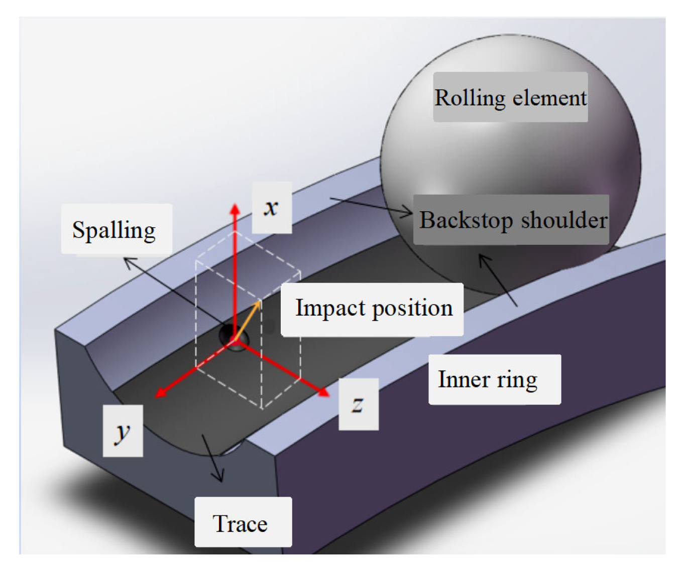
2. Dynamic Modeling of Spalling Faults at Non-Central Positions of the Inner-Ring Raceway

Deep groove ball bearings are usually not designed to withstand axial forces, but in practical applications, they may be affected by weak axial shocks. When the deep groove ball bearing bears a certain axial force, the inner and outer ring roller channel and rolling experience undergo relative displacement to adjust the centripetal direction and form a new balance state. In this case, contact angles are generated, similar to the operation of angle contact ball bearings. But the contact angle of deep groove ball bearings is usually smaller, and they return to the original working mode after the end of impact. It is found that the material defects in the manufacturing process are also one of the main causes of the spalling failure. If the bearing material strength is insufficient, it also leads to axial impact, so the spalling failure may occur in the non-center position of the roller path. As shown in Figure 1. At this time, the bearing is no longer symmetrical in the radial perspective, and the rolling body will make uneven contact with the rolling path when it moves between the rollers, which leads to the derived axial impact and reduces the axial stability and service life of the bearing system.
To facilitate the analysis of the influence of spalling faults on the bearing system, the following assumptions are proposed in this paper: All contact deformations are based on Hertz contact theory; the rolling elements are equivalent to linear spring-dampers connecting the inner and outer ring raceways; the inner and outer ring raceways are rigid; the outer ring is fixed, the inner ring rotates with the shaft without slipping, and the rolling elements do not slip within the raceways; the effects of the cage, lubricating oil, and temperature rise are not considered. Under reasonable conditional assumptions, a simplified model for the rolling bearing system is shown in Figure 2.

2.1. Rolling Element Deformation Quantity

In this work, the theoretical analysis of a three-dimensional structure and motion characteristics of rolling bearing is made. Taking the 6205 deep groove ball bearing as an example, the bearing parameters are shown in Table 1. Considering that when the spalling fault occurs in the non-center position of the raceway, the bearing under the radial view angle is not symmetrical, and the movement direction of the rolling element is affected, the axial position of the raceway is introduced into the establishment condition of the model. Extend a z-axis on the x/y plane to describe the axial position of the spalling defect in the raceway, thereby establishing a three-dimensional mathematical model of the deep groove ball bearing, and on this basis, analyze the forces between the rolling element and the groove under different sections. Analyze the rolling ball bearing with single-point pitting failure under three-dimensional conditions, and decompose it into two sectional plane views, as shown in Figure 3, plan view of x-axis and y -axis sections as shown in Figure 3a, plan view of x-axis and z-axis sections as shown in Figure 3b.
The rolling elements within the load area are deformed by the load distributed at their positions, causing an offset between the circle centers of the inner and outer rings of the bearing. This offset is the sum of the deformation vectors of all the rolling elements. Among them, δ i is the contact deformation of the i-th bearing rolling element, which is expressed as:
δ i = x cos θ i + y sin θ i 0.5 C r cos τ + z sin τ
where, x , y and z are the offsets of the bearing’s center of mass decomposed in the x , y and z directions, respectively; C r is the bearing clearance; θ i is the position angle of the i-th rolling element relative to the x axis, and it can be expressed as:
θ i = ω c t + 2 π ( j 1 ) Z + θ 0
where, θ 0 is the initial position angle of the first rolling element; z is the number of rolling elements; ω c is the angular velocity of the rolling element around the bearing circle center, and it can be expressed as:
ω c = 1 2 ( 1 d b D w cos β ) ω s
where, d b is the diameter of the rolling element; D w is the pitch diameter; β is the bearing contact angle; ω s is the rotor angular velocity; and it can be expressed as:
ω s = 2 π n 60
where, τ is the position angle of the pitting on the raceway relative to the center of the rolling element, as shown in Figure 3b. ϕ s p a l l is the radial position angle of the fault center point. ϕ d is the half of the circle center position angle of the spalling fault, and the calculation formula is:
φ d = arcsin L d b
where, L is the length of the spalling fault, and d b is the diameter of the rolling element.

2.2. Time-Varying Energy of Rolling Elements in Spalling Area

According to the law of conservation of energy, for a rolling bearing with spalling defects on the raceway, the energy of the rolling elements will change when passing through the defective area, causing energy fluctuations in the entire bearing system and thus triggering vibration responses. The contact deformation and movement speed are the main influencing factors of energy change, and the movement state of the rolling element when passing through the defect area is determined by its internal contour. Therefore, the length, width, and depth of the spalling defect are set as fixed values, and the defect slope and the time-varying energy of the rolling element when passing through are quantitatively studied.
Circle center trajectory is shown in Figure 4, which is a sinusoidal trajectory. When the rolling element enters the defect area, the elastic deformation will be released, and the released elastic deformation is equal to the offset of the circle center relative to the pitch diameter of the bearing. According to the geometric relationship between the rolling element and the defect contour and the judgment of the vector direction, when the rolling element enters the defect area, it only contacts the entry end. At this time, the deformation is gradually released, the elastic potential energy decreases, and the kinetic energy increases until it runs to the circle center trajectory of the defect and leaves the contact end. This entry of the circle trajectory can be approximated as a half-sine curve. Next, the circle center trajectory is completed around the leaving end. The elastic potential energy gradually increases, and the kinetic energy decreases. According to the geometric relationship, the formula for the release of elastic deformation is established as:
δ = H o ( 1 cos π θ i ω t φ s p a l l 2 ϕ d A B H o ( 1 cos π θ i ω t φ s p a l l 2 ϕ d B C 0 e l s e w h e r e
where, H o is the maximum submergence depth of the V -shaped trajectory, and the calculation formula is as follows:
H o = tan α L 2 d b tan ( α 2 ) 2
Establish an expression for the movement speed V y in the y -direction of the rolling element with a circular-arc-type trajectory:
V y = V x ( 1 cos π θ i ω t φ s p a l l 2 ϕ d A B V x ( 1 cos π θ i ω t φ s p a l l 2 ϕ d B C 0 e l s e w h e r e
The energy formula of the rolling element:
E m = E r + E k
where, E m is the energy of the rolling element, E r is the potential energy, and the calculation formula is:
E r = m 0 g δ + 1 2 K δ 1.5
where, m 0 is the mass of the rolling element; δ is the submergence distance of the rolling element’s circle center; K is the elasticity coefficient; g is the gravitational coefficient, taken as 9.81 m/s²; E k is the kinetic energy, and the calculation formula is as follows:
E k = 1 2 m 0 v x 2 + v y 2
where, v x is the motion speed of the rolling element in the x-direction;  v y is the speed of the rolling element in the y-direction.

2.3. Rolling Element-Raceway Contact Area

The actual contact position is within the contact elliptical area. As shown in Figure 5a, if the spalling fault occurs outside the contact elliptical surface, it will not have an impact on the bearing. As shown in Figure 5b, if the spalling fault occurs at the circle center of the contact elliptical surface, a single radial impact will be generated. As shown in Figure 5c, if the spalling fault occurs at a non-central position of the contact elliptical surface, a radial impact and a derived axial impact will be generated.
It can be seen from this that the location of the spalling defect must be within the contact stress area; otherwise, it will not cause the bearing to vibrate. As shown in Figure 6, the boundary condition of the axial position angle τ of the spalling fault is:
τ arcsin a r b
where, r b is the radius of the rolling element, and the formula for calculating the major axis 2 a of the contact-area ellipse is:
2 a = μ 24 1 1 m 2 Q E ρ 1 3
The formula for calculating the minor axis 2 b of the contact area ellipse is:
2 b = ν 24 1 1 m 2 Q E ρ 1 3
According to the geometric relationship between the rolling element and the raceway, the axial pressure in the contact elliptical area is the same, and the radial direction is affected by the curvature of the inner ring, with the edge pressure being small and the middle pressure being the maximum. The contact stress P m a x of the elliptical area is calculated by Hertz contact theory, and the formula is:
P max = 1.5 π 3 E 1 1 m 2 2 3 1 μ ν ρ 2 3 Q 1 3
where, E is the elastic modulus (for steel it is 208,000 MPa), m is the Poisson’s ratio (for steel it is 10/3), Q is the load of the rolling element, and ρ is the sum of the principal curvatures. The calculation formula is:
ρ = 1 D w 4 1 f ± 2 γ 1 γ
γ = d b D p w
where, f represents the ratio of the raceway radius to the radius of the rolling element, and D p w is the pitch circle diameter.

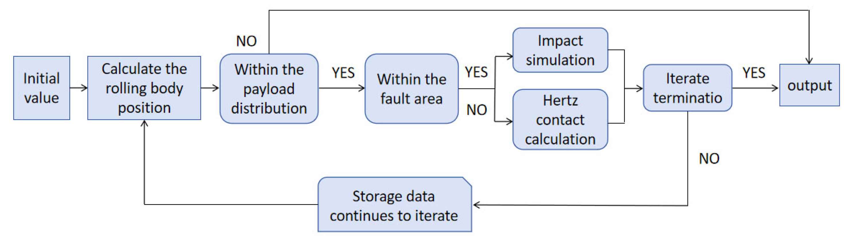
2.4. Establish Fault Dynamics Equation

As shown in Figure 7, in the three-dimensional structure, the total amount of energy change when the rolling element passes through the defect remains unchanged. Due to the symmetry of the axial structure, when the rolling element is in the normal raceway area, the deformation in the z-direction in the x/z plane will cancel each other out. However, when the rolling element passes through the defect, the impact of the defect on it needs to be considered. In the x/z plane, the deformation projected in the x/z direction is directly related to the position angle τ where the pitting defect occurs. The expression is as follows:
x = δ 1 sin θ cos τ y = δ 1 cos θ cos τ z = δ 1 sin τ
It can be seen from Figure 6 the force change of the rolling element when it passes through the raceway: When the rolling element is in the normal area, due to the symmetry of the bearing structure in the x/z direction, the forces in the x/z plane cancel each other out. In the fault area, the balance is broken, so an impact will be generated in the fault point area. The energy fluctuations decomposed in the x, y, and z directions can be expressed as:
e r x = E r sin θ cos τ e r y = E r cos θ cos τ e r z = E r sin τ
Establish the dynamic equation of spalling fault in rolling bearings with three degrees of freedom.
M x ¨ + C x ˙ + F h , x + e r x x γ = F x M y ¨ + C y ˙ + F h , y + e r y y γ = F y M z ¨ + C z ˙ + F h , z + e r z z γ = F z

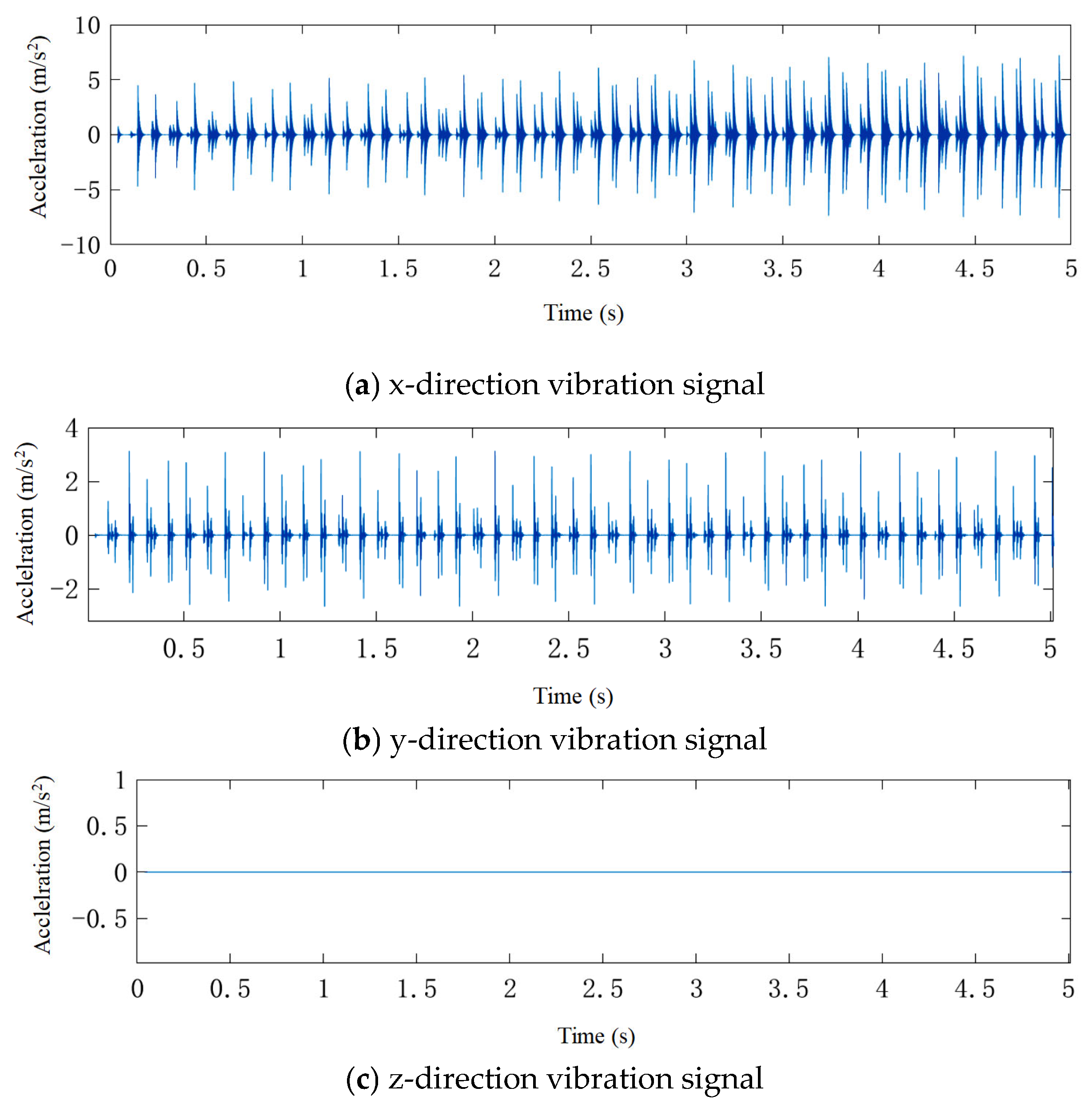
3. Model Calculation Results

Through MATLAB (R2022b) software, the fourth-order Runge-Kutta method is used to calculate the dynamic equations. The initial displacements and velocities in the x and y directions are 0.000001 m, the time step is set t = 1 × 10 6   s , the simulation duration is 5 s; the additional loads are Fx = 50 N, Fy = 0 N, and Fz = 0 N; the rotational speed is set to 600 r/min; and simulation calculations are carried out for the axial position angles τ of the defect being 0° and 15°. The calculation flow is shown in Figure 8. First, rolling body position and load distribution area are calculated, and then the response of the rolling body is calculated by impact simulation in the fault area, while the non-fault area is calculated by Hertz contact mode. The computational data are stored and iterated until the iteration ends.
It can be found from Figure 9 that when the axial position angle of the fault is τ = 0 ° , vibration responses occur in both the x and y directions, but there is no vibration response in the z direction. This indicates that when only subjected to a radially constant direction load, there will be no axial vibration impact.
In Figure 10, when the axial position angle of the fault is τ = 15 ° , vibration signals appear in the x, y, and z directions. After the vibration signals are processed by the root mean square, they are shown in Table 2.

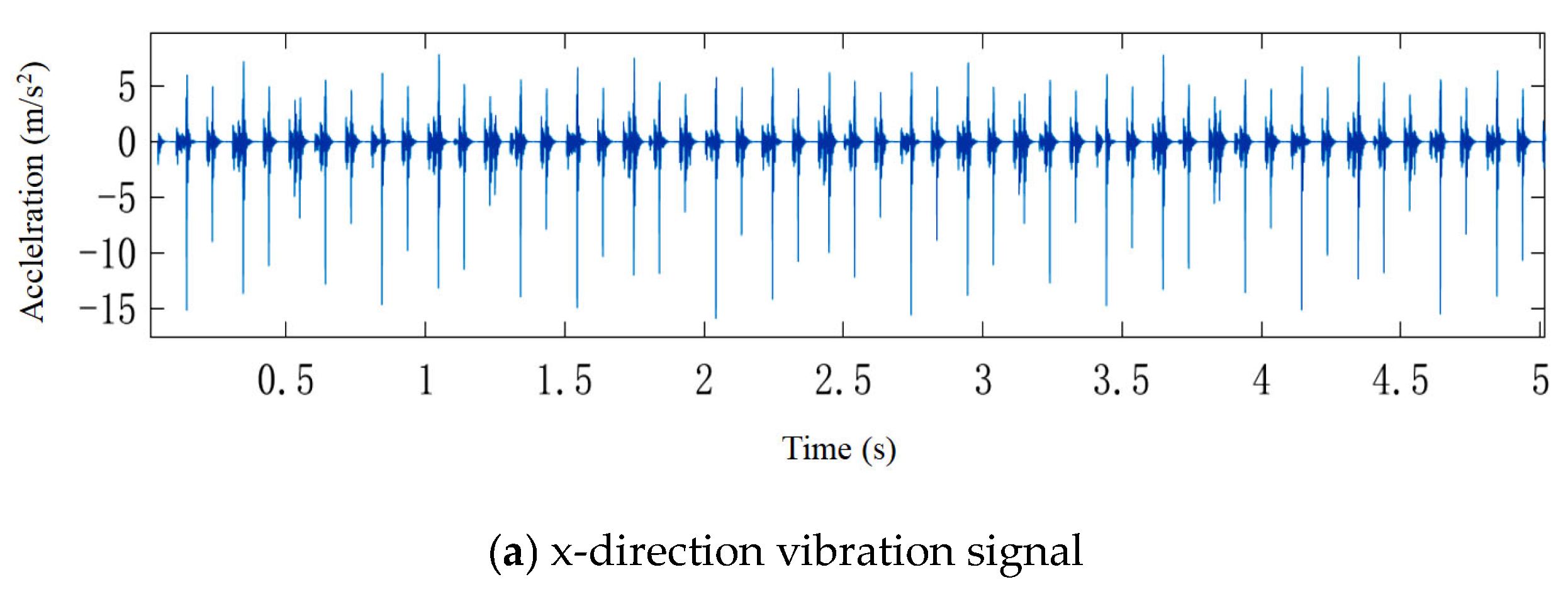
4. Simulation and Experiment Validation

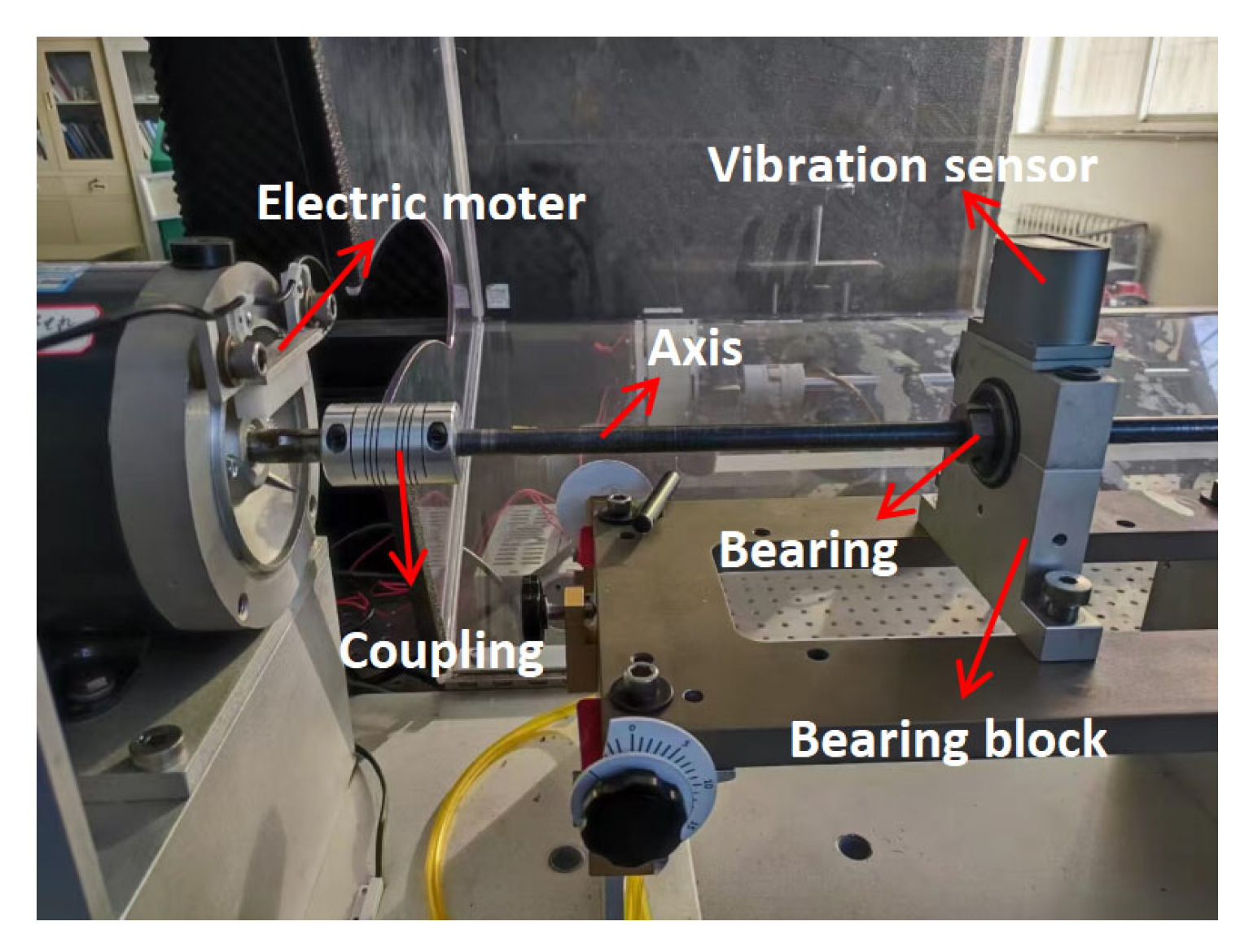
4.1. Experimental Procedure

To validate the effectiveness of the fault dynamics model studied in this article, the vibration signal acquisition experiment of rolling bearing inner ring spalling fault was carried out on the bearing vibration signal acquisition test bench, as shown in Figure 11. The experimental equipment includes a shaft with a shaft diameter of 1/2 inch, which is connected to a load motor through a flexible coupling to avoid the influence of motor vibration on the experimental results, a bearing pedestal for fixing the bearing, and a vibration signal collection sensor. The outer ring is fixed in the bearing seat; the inner ring is in an interference fit on the shaft and rotates with the shaft. The coupling connects the motor to the shaft, and the sensor is fixed at the top of the bearing seat. The sampling frequency is 102.4 kHz and processed utilizing MATLAB (R2022b) software. The experimental results are shown in Figure 10.
In order to avoid randomness in the experiment, several bearings with the same type of fault were selected, and these bearings came from the same factory batch. Conduct multiple experiments and select the optimal experimental results for comparison with simulation results. The type of deep groove ball bearing used in the experiment is 6205, and the specific parameters are shown in Table 1. Processing is carried out at the center position of the inner raceway by drilling, and the peeling axial position is τ = 0 ° as shown in Figure 12a. Processing is carried out at the non-center position of the inner raceway by drilling, and the peeling axial position is τ = 15 ° , as shown in Figure 12b. τ is the position angle of the peeling path relative to the center of the rolling body. Both spalling fault size parameters are the same, with a diameter of 2 mm and a depth of 0.5 mm. The experimental results were shown in Figure 13.
Figure 13 shows the time domain of the measured vibration signal in x, y, and z at τ = 0 ° and τ = 15 ° at the experimental stage. From the figure, it can be seen that the amplitude fluctuations of the measured signal exhibit periodicity similar to the simulated signal. When the peeling fault occurs in the center area of the raceway, the axial impact generated is relatively small. While the axial impact generated in the non-center area of the raceway increases, the vibration signal strength in the x-direction decreases, and the vibration signal in the y-direction is not affected.

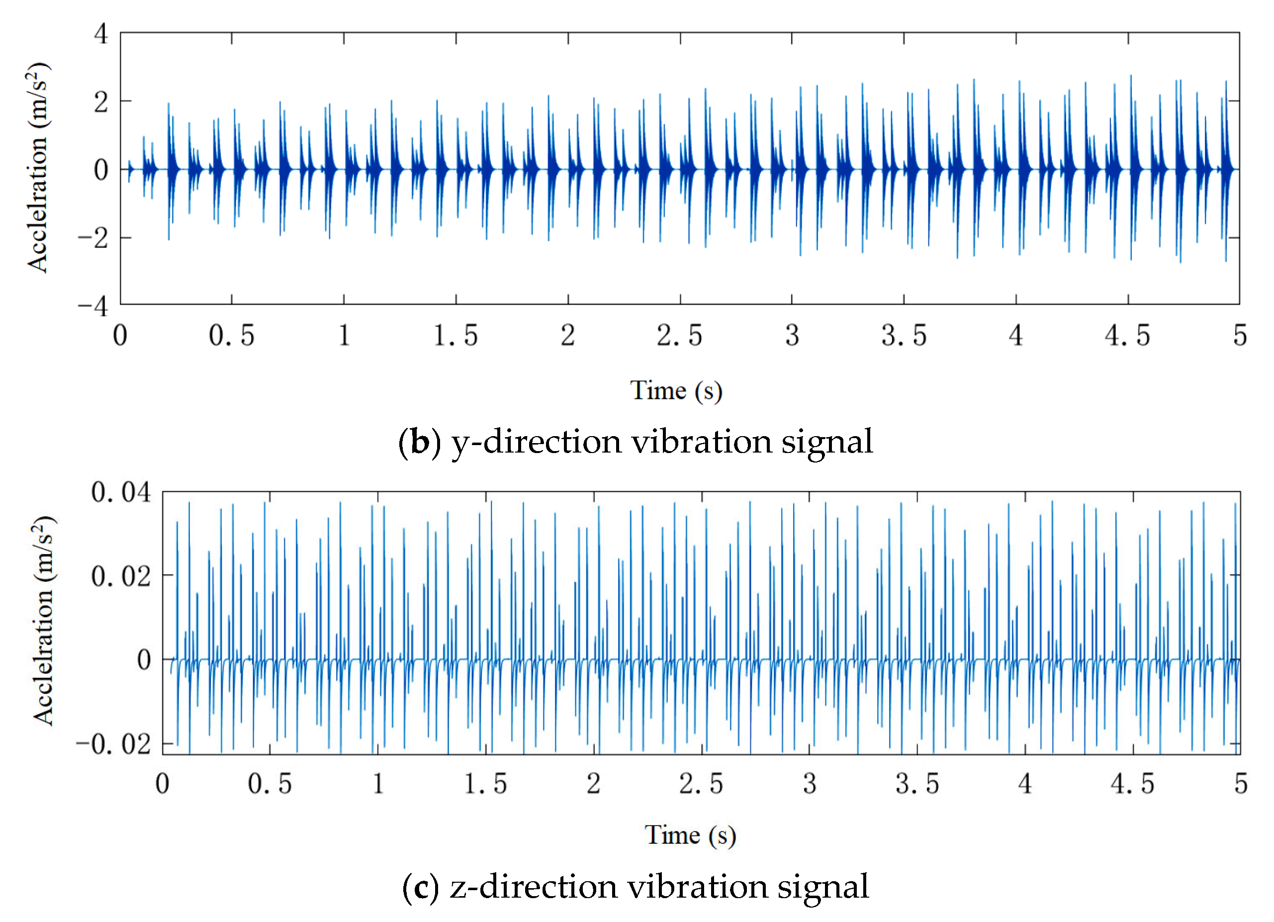
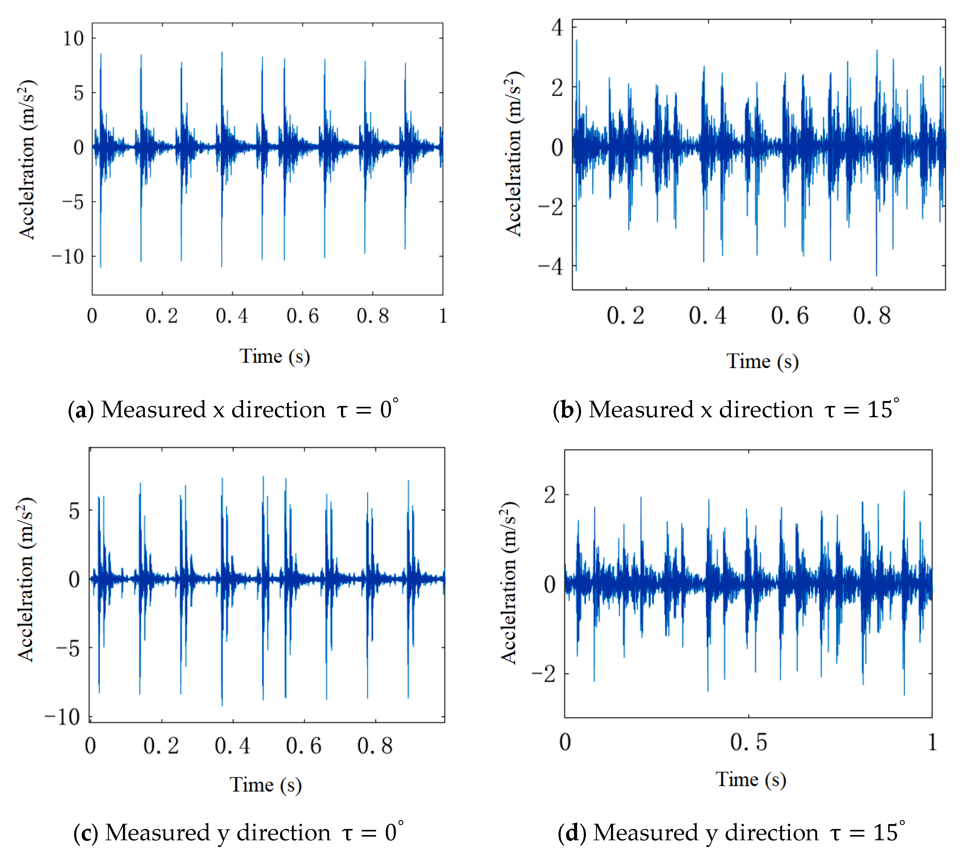
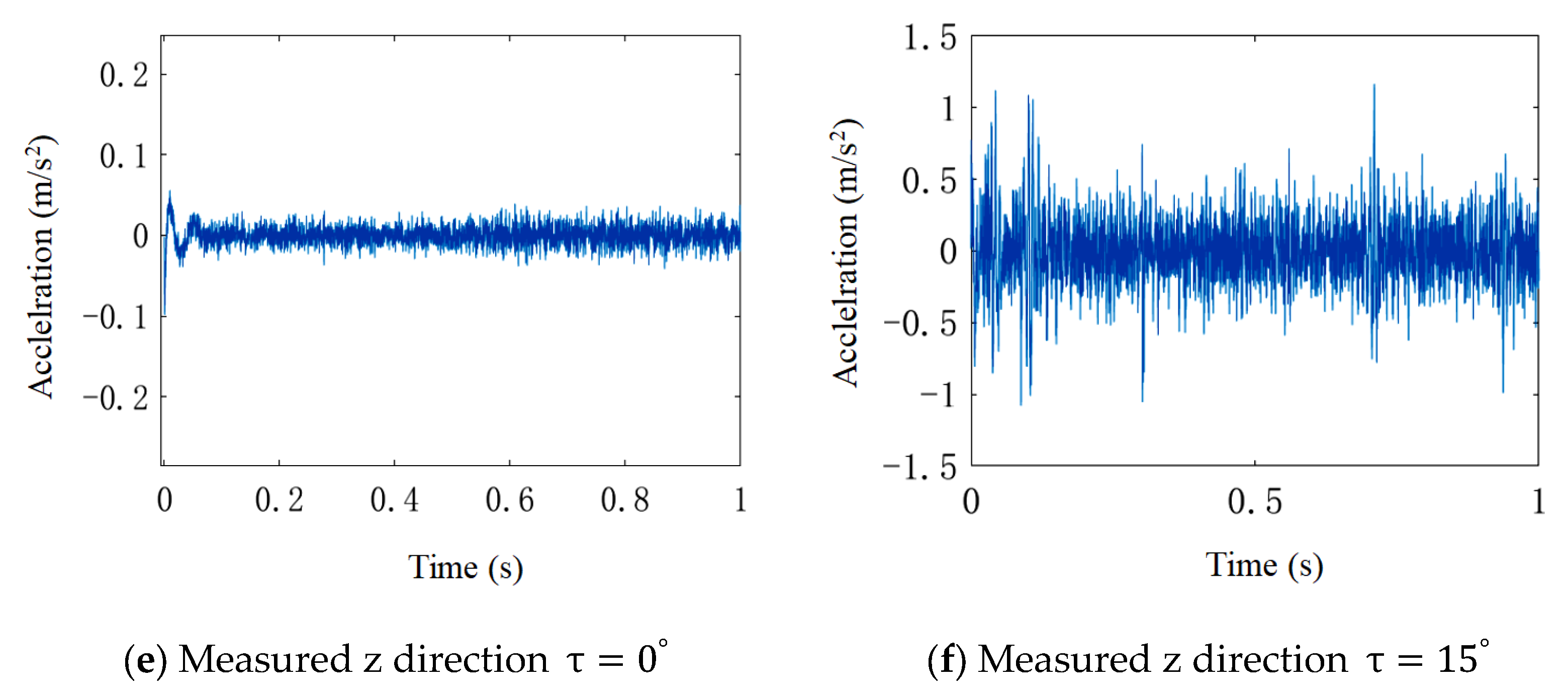
4.2. Envelope Spectrum Analysis of Simulated and Measured Signals

To verify the effectiveness of the proposed model, the envelope spectrum analysis method was used to compare and analyze simulation and experimental data. The formula for calculating the characteristic frequency of bearing inner ring faults is:
f i = 1 2 · Z · ω c 1 + d b D W
where, z is the number of rolling elements; ω c is the angular velocity of the rolling element around the bearing circle center; d b is the diameter of the rolling element; D w is the pitch diameter.
Simulation and experimental datasets with a load of 50 N and a speed of 600 r/min were used for comparative analysis, in which the sampling frequency (fs) was 1024, and when the rotating shaft frequency was 10 Hz, the characteristic vibration frequency of spalling failure of the bearing inner ring was calculated by Formula (21) as 54.388 Hz. Envelope analysis was carried out on the simulation and measured data of bearings, as shown in Figure 14. Figure 14a shows the envelope diagram of the non-center position simulation signal, and it can be clearly observed that the peak frequency conforms to the fundamental frequency of 10 Hz and the characteristic frequency of 54 Hz and their harmonics. Figure 14b shows the envelope diagram of the non-center position measured signal, and its peak frequency may appear around the characteristic frequency due to other factors, but it is also very close. There are many side frequencies around each characteristic frequency; this is due to the modulation phenomenon caused by the inner ring rotating with the axis when the fault occurs. Through comparative analysis, the calculated results of the model in this paper are basically consistent with the characteristic frequencies of the experimental results, which proves that the model in this paper is effective.

4.3. Amplitude Root Mean Square Analysis of Simulation and Measured Signals

Verify that this model has good computational results, the root mean square (RMS) processing is applied to the vibration signal in the z-axis direction. The X R M S calculation formula is as follows:
X R M S = 1 N f i = 1 N f x i 2
where, x i is the response of the i-th vibration signal, and N f is the length of the vibration signal.
Table 2 and Table 3 show the root mean square values of the simulation signals in three directions for the spalling axial position τ = 0 ° and τ = 15 ° . It can be seen from the comparison of the vibration root mean square values at the same fault location under radial load that the root mean square value is highest in the x-direction and lowest in the z-direction. The root mean square value in the z-direction at the axial position τ = 0 ° of the spalling fault is 0. When the axial position is τ = 15 ° , the root mean square value of the z-direction vibration signal increases to 0.615. There is no change in the y-direction, while the value in the x-direction decreases by 22.9%. Comparing Table 3, which shows the root mean square values of the measured signals in three directions for the spalling axial positions τ = 0 ° and τ = 15 ° , the simulation and experimental results are close to each other. The simulation and experimental loading conditions for the two bearings are the same. Thus, it shows that when the axial position of the spalling fault is far away from the center of the raceway, the vibration signal in the x-direction will be weakened, the vibration signal in the z-direction will be enhanced, and the vibration signal in the y-direction will not be affected.

5. Conclusions

This paper considers the vibration response of the bearing system when the spalling fault occurs at non-center positions on the raceway. A force analysis was conducted on bearings subjected to radial loads from a three-dimensional perspective, and the Hertz contact deformation area between the rolling elements and the raceway was calculated and described the position conditions of the spalling fault causing axial impact in the axial direction of the raceway. And the impact characteristics of spalling faults at different axial positions of the inner raceway were studied, thus proposing a three-degree-of-freedom dynamic model considering axial impact. Through simulation and experimental comparison analysis, the results show that the simulation and experimental results were similar, which verifies the effectiveness and accuracy of the model. When the spalling fault occurs in the non-central area of the raceway, it will generate axial impact and reduce the vibration signal intensity in the x direction, while the vibration signal in the y direction is not affected.
The research made some achievements in the analysis of bearing peeling failure dynamics, but some aspects need to be improved. First, the time-varying stiffness of the rolling body through the peeling defect region. The existing time-varying stiffness is the contact stiffness change studied in the two-dimensional plane. In fact, both the rolling body and the inner coil rolling road are three-dimensional, so the time-varying stiffness is more in line with the actual situation with the spatial variation in deformation. Secondly, three-degrees of freedom dynamics can only simulate whether the axial impact is generated, and further development needs to be performed to realize the predicted axial impact amplitude.

Author Contributions

Conceptualization, S.L. and W.M.; methodology, S.L.; software, L.W.; validation, L.W., S.L. and W.M.; investigation, J.W.; data curation, J.W.; writing—original draft preparation, L.W. and Z.G.; writing—review and editing, S.L. and W.M.; visualization, W.M.; supervision, S.L.; project administration, S.L. and W.M.; funding acquisition, W.M. All authors have read and agreed to the published version of the manuscript.

Funding

This research was funded by: National Natural Science Foundation of China (Grant No. 52205163), Youth Projects of Basic Scientific Research Projects in Colleges and Universities for Liaoning Provincial Education Department (JYTQN2023383), National Defense Key Laboratory Open Foundation of Aerospace Manufacturing Process of Shenyang Aerospace University (No. SHSYS202408).

Institutional Review Board Statement

Not applicable.

Informed Consent Statement

Not applicable.

Data Availability Statement

The original contributions presented in this study are included in the article. Further inquiries can be directed to the corresponding author.

Conflicts of Interest

The authors declare no conflicts of interest. The funders had no role in the design of the study; in the collection, analyses, or interpretation of data; in the writing of the manuscript, or in the decision to publish the results.

References

  1. Chen, H.; Jiang, D.; Zhuo, W.; Sun, H.; Ma, W. Failure Analysis of a Helicopter Engine Bearing Wear. Aviat. Maint. Eng. 2022, 12, 57–59. [Google Scholar] [CrossRef]
  2. Luo, M.; Guo, Y.; Andre, H.; Wu, X.; Na, J. Dynamic modeling and quantitative diagnosis for dual-impulse behavior of rolling element bearing with a spall on inner race. Mech. Syst. Signal Process. 2021, 158, 107711. [Google Scholar] [CrossRef]
  3. Desnica, E.; Ašonja, A.; Radovanović, L.; Palinkaš, I.; Kiss, I. Selection, Dimensioning and Maintenance of Roller Bearings. In 31st International Conference on Organization and Technology of Maintenance; Springer: Cham, Switzerland, 2022; Volume 592, pp. 133–142. [Google Scholar] [CrossRef]
  4. Wang, Y.; E, S.; Jia, Y.; Ma, X.; Xie, B. Improved model for quasi-static mechanical analysis of angular contact ball bearing under joint load. Bearing 2022, 11, 18–26. [Google Scholar] [CrossRef]
  5. Tian, J.; Ai, X.; Liu, L.; Zhang, F.; Wang, Z. Modeling of composite fault dynamics and vibration characteristic analysis of intermediary bearings. Vib. Impact 2022, 41, 144–151. [Google Scholar] [CrossRef]
  6. Mu, X.; Liu, Z. Dynamic response and life analysis of box bearing cage of EMU. Bearing 2023, 3, 18–26. [Google Scholar] [CrossRef]
  7. He, A.; Wang, X. Nonlinear dynamics modeling of the rotor with the bearing inner ring gap. Mech. Manuf. Autom. 2022, 51, 124–128. [Google Scholar] [CrossRef]
  8. Wan, C.; Zhang, K.; Tian, Z.; Chen, X.; Li, L. Study on the relationship between contact stress distribution characteristics and fatigue peeling of angle contact ball bearing at high speed. Mech. Drive 2021, 45, 38–44. [Google Scholar] [CrossRef]
  9. Pastukhov, A.; Timashov, E.; Stanojević, D. Temperature Conditions and Diagnostics of Bearings. Appl. Eng. Lett. 2023, 8, 45–51. [Google Scholar] [CrossRef]
  10. Ou, X.; Zhang, Y.; Zhang, K.; Wang, B. A deep groove ball bearing dynamics model considering unbalanced forces and disturbed dynamics. Mech. Des. Manuf. 2022, 12, 6–10. [Google Scholar] [CrossRef]
  11. Petersen, D.; Howard, C.; Sawalhi, N.; Ahmadi, A.M.; Singh, S. Analysis of Bearing Stiffness Variations, Contact Forces and Vibrations in Radially Loaded Double Row Rolling Element Bearings with Raceway Defects. Mech. Syst. Signal Process. 2015, 50–51, 139–160. [Google Scholar] [CrossRef]
  12. Dong, Q.Q.; Wei, H.J.; Ma, G.W. Failure Mechanism of S-Shaped Fissure In Brittle Materials Under Uniaxial Tension: Experimental and Numerical Analyses. Int. J. Solids Struct. 2020, 119–192, 486–496. [Google Scholar] [CrossRef]
  13. Cao, H.; Wang, D.; Zhu, Y.; Chen, X. Dynamic modeling and abnormal contact analysis of rolling ball bearings with double half-inner rings. Mech. Syst. Signal Process. 2021, 147, 107075. [Google Scholar] [CrossRef]
  14. Madar, E.; Galiki, O.; Klein, R.; Bortman, J.; Nickell, J.; Kirsch, M. A new model for bearing spall size estimation based on oil debris. Eng. Fail. Anal. 2022, 134, 106011. [Google Scholar] [CrossRef]
  15. Shi, J.; Yu, T.; Goebel, K.; Wu, D. Remaining Useful Life Prediction of Bearings Using Ensemble Learning: The Impact of Diversity in Base Learners and Features. J. Comput. Inf. Sci. Eng. 2021, 21, 021004. [Google Scholar] [CrossRef]
  16. Liu, Q.; Guo, Y.; Wu, X. Modeling of double impact characteristic mechanism of rolling bearing outer ring peeling fault. J. Vib. Eng. 2017, 30, 670–678. [Google Scholar] [CrossRef]
  17. Chang, B.; Yan, C.; Yuan, H.; Kang, J.; Wang, K.; Wu, L. Dynamic modeling of rolling bearing under multi event excitation. Vib. Impact 2018, 37, 16–24. [Google Scholar] [CrossRef]
  18. Xie, C.; Hao, L.; Deng, S.; Qian, D.; Hua, L. Nonlinear system of high-speed bearing rotor with outer race peeling off and its vibration response analysis. Vib. Shock 2022, 41, 262–269. [Google Scholar] [CrossRef]
  19. Cui, L.; Zhang, Y.; Zhang, F.; Zhang, J.; Lee, S. Vibration response mechanism of faulty outer race rolling element bearings for quantitative analysis. J. Sound Vib. 2016, 364, 67–76. [Google Scholar] [CrossRef]
  20. Jiang, Y.; Huang, W.; Luo, J.; Wang, W. An improved dynamic model of defective bearings considering the three-dimensional geometric relationship between the rolling element and defect area. Mech. Syst. Signal Process. 2019, 129, 694–716. [Google Scholar] [CrossRef]
  21. Shi, H.; Liu, Z.; Bai, X.; Li, Y.; Wu, Y. A Theoretical Model with the Effect of Cracks in the Local spall of Full Ceramic Ball Bearings. Appl. Sci. 2019, 9, 4142. [Google Scholar] [CrossRef]
  22. Li, Y.; Li, Z.; Tao, J.; Xu, B. Dynamic model of single point fault of outer ring of rolling bearing considering progressive deformation and lubricant. Bearing 2021, 9, 14–19. [Google Scholar] [CrossRef]
  23. Tu, W.; Liang, J.; Luo, Y.; Zhou, J.; Zhou, S. Research on dynamic load characteristics of rolling bearings under accelerated working conditions. Vib. Shock 2021, 40, 152–159. [Google Scholar] [CrossRef]
Figure 1. Bearing inner ring raceway non-center spalling fault.
Applsci 15 02740 g001
Figure 2. Rolling bearing model diagram.
Applsci 15 02740 g002
Figure 3. Three-dimensional load distribution of bearings.
Applsci 15 02740 g003
Figure 4. Circle center trajectory.
Applsci 15 02740 g004
Figure 5. Spalling fault-contact ellipse position.
Applsci 15 02740 g005
Figure 6. Contact ellipse parameters of rolling body-inner race raceway.
Applsci 15 02740 g006
Figure 7. Vibration and shock in three-dimensional space.
Applsci 15 02740 g007
Figure 8. Model solving flowchart.
Applsci 15 02740 g008
Figure 9. Simulation results of fault axial position 0°.
Applsci 15 02740 g009
Figure 10. Simulation results of fault axial position 15°.
Applsci 15 02740 g010aApplsci 15 02740 g010b
Figure 11. Bearing vibration signal acquisition experimental platform.
Applsci 15 02740 g011
Figure 12. Physical picture of bearing with inner ring peeling off.
Applsci 15 02740 g012
Figure 13. Time domain diagram of measured signal.
Applsci 15 02740 g013aApplsci 15 02740 g013b
Figure 14. Simulation and measured signal envelope diagrams. (a) Envelope diagram of the non-center position simulation signal (b) Envelope diagram of the non-center position measured signal.
Applsci 15 02740 g014
Table 1. 6205 Bearing parameter table.
ParameterNumerical Value
The inner raceway diameter Di/mm25
The outer raceway diameter Db/mm52
Pitch circle diameter
Dw/mm
38.5
Rolling element diameter
db/mm
7.9
Number of rolling elements
Z
9
Radial clearance
Cr
1
Rolling element mass
m0/g
2.14
Table 2. Root mean square comparison of simulated vibration signals.
Vibration DirectionAxial Position
τ   =   0 °
Axial   Position   τ   =   15 ° Year-on-Year Growth
x0.25900.1997−22.9%
y0.11130.11130%
z00.615++
Table 3. Root mean square comparison of measured vibration signals.
Vibration DirectionAxial Position
τ   =   0 °
Axial   Position   τ   =   15 ° Year-on-Year Growth
x0.26770.2077−22.4%
y0.12590.1274+1.2%
z0.00730.0847++
Disclaimer/Publisher’s Note: The statements, opinions and data contained in all publications are solely those of the individual author(s) and contributor(s) and not of MDPI and/or the editor(s). MDPI and/or the editor(s) disclaim responsibility for any injury to people or property resulting from any ideas, methods, instructions or products referred to in the content.

