1. Introduction
The microwave sounder plays a crucial role in the field of atmospheric detection and is one of the important remote sensing tools used for meteorological and disaster monitoring on our polar-orbiting meteorological satellites [
1,
2]. The antenna and receiver are the core of the microwave atmospheric sounder system, and the antenna is driven by a rotating mechanism for scanning and regular ground observation [
3]. In order to increase the ground observation time [
4], a variable speed scanning mode is introduced. This makes satellite platforms with high-precision attitude control place higher perturbation moment requirements on the payload. By reconfiguring the planar antenna reinforcement, the platform’s perturbation moment requirement for the payload can be met.
Numerous scholars have carried out in-depth and extensive research on improving structural performance through the design of reinforcement. Li Wei et al. [
5] simulated changes in the number and height of the reinforcement bars of the reflector antenna. The results show that increasing the number of reinforcement bars significantly improves the stiffness of the reflective surface. Additionally, the effect of increasing the number of circumferential reinforcement bars is more significant. In addition, increasing the height of reinforcing bars enhances the fundamental frequency of the antenna structure. Zhou T et al. [
6], in their study, carefully divided the reflector surface antenna into zones, designed the reinforcing bars at the boundary of each zone, and further laid out the reinforcement bars in the circumferential and radial directions according to the unique characteristics of the reflector surface. In addition, additional auxiliary reinforcements were added at the contours of the reflector surface to create the final structural layout. This design not only significantly improves the stability of the overall structure but also effectively reduces its weight.
Compared with traditional designs that rely on the expertise of designers, topology optimization technology greatly facilitates the accurate calculation of material layouts and dimensions by setting specific response types, response constraints, and optimization objectives. Currently, this technique has been widely and deeply studied in several fields, such as structural design [
7,
8,
9,
10,
11,
12,
13,
14,
15]. Niu Bin et al. [
16] studied the vibration of thin-walled reinforced structures in dynamic environments and proposed an integrated design method that combines the layout of reinforcing ribs with damping layer topology. This method creates a synergistic optimization model that minimizes dynamic flexibility by optimizing both the damping material distribution and the reinforcement layout, with a focus on thin-walled reinforced plate structures. Chen T Y et al. [
17] adopted a topology and size optimization approach to redesign the layout and thickness of reinforcing bars, with the aim of minimizing the weight of the reinforcement. Wang J et al. [
18] set the normal acceleration in a specific region as the core objective of topology optimization and constructed an optimization model based on this. The rib layout was reconstructed, and different optimized layouts were obtained according to different excitation conditions. In the area of controlling and optimizing the antenna perturbation moment, more of the literature focuses on reducing the perturbation moment by optimizing the control algorithm or performing moment compensation [
19,
20,
21,
22,
23,
24].
The structural optimization design of the reflective surface reinforcement of the antenna scanning drive mechanism is crucial for increasing the dynamic stiffness of the structure and reducing rotational inertia. It also helps to reduce the effect of moment perturbation. However, in many existing designs, the layout and sizing of the reinforcement bars are mostly dependent on the experience of the designer and lack a supporting theoretical basis. This leads to suboptimal layout and sizing in many designs, deviating from the ideal conditions for optimal design.
In order to address the challenges associated with the reflective surface structure of the antenna scanning drive mechanism, this paper proposes a design method that integrates both topology optimization and size optimization. This integrated approach is progressive, where topology optimization lays the foundation by providing the initial design direction and defining the optimal material distribution for the structure. Once the topology is established, size optimization comes into play to precisely adjust the dimensions of the reinforcement, ensuring that the structural stiffness requirements are met while simultaneously optimizing the distribution of mass for improved performance. By combining these two complementary optimization techniques, this method achieves a balanced solution that enhances the overall structural efficiency, reduces rotational inertia, and improves dynamic stiffness, ultimately improving the stability and operational performance of the antenna scanning drive mechanism. The topology optimization adopts the volume as the constraint, the objective function is the maximum first-order frequency, and the results show that the layout of the reinforcement bar along the center presents a “palm”-shaped arrangement, which can significantly increase the first-order intrinsic frequency. Based on the topological configuration of the reflecting surface reinforcement structure, the size optimization of the reflecting surface is carried out. Here, the design variables are the thickness of the reflecting surface and the cross-section size of the reinforcement. The objective of such size optimization is to reduce the rotational moment of inertia of the structure, and the constraints are the dynamic stiffness and the RMS of the structure’s stress value. The structure’s dynamic stiffness improves after the size optimization, and the mass of the reinforcement is significantly reduced. Additionally, the planar antenna’s rotational moment of inertia is lower, leading to a reduction in the disturbance moment at both uniform and variable speeds. It is important to adjust the dynamic stiffness and the moment of inertia of the system, which helps to minimize the effect of moment perturbation.
In this article, the authors explore the optimization design of reinforcement structures in antenna scanning mechanisms for spaceborne microwave sounders.
Section 2 describes the scanning drive mechanism, highlighting disturbance moments from motor torque and dynamic imbalance.
Section 3 covers topology optimization, aiming to increase structural dynamic stiffness while reducing rotational inertia by optimizing the reinforcement layout.
Section 4 discusses size optimization based on topology results, minimizing rotational inertia and improving system stability, ensuring that the structure is both lightweight and efficient. The conclusion emphasizes the combined benefits of topology and size optimization, resulting in reduced mass and rotational inertia, improved dynamic stiffness, and better control precision, which are suitable for high-stability satellite attitude control.
This work presents a novel method combining topology and size optimization to enhance dynamic stiffness and reduce the rotational inertia of the antenna’s reinforcements. By maximizing the first-order frequency and minimizing torque disturbances, this approach improves both performance and stability. It offers a more precise and scientifically supported design, moving beyond traditional, experience-based methods. This contributes to better satellite attitude control and system stability.
2. Introduction to the Antenna Structure of the On-Board Microwave Sounder
The scanning drive mechanism of the spaceborne microwave-sounding antenna consists of two planar reflective surfaces driven by a permanent magnet servomotor. It is shown in
Figure 1.
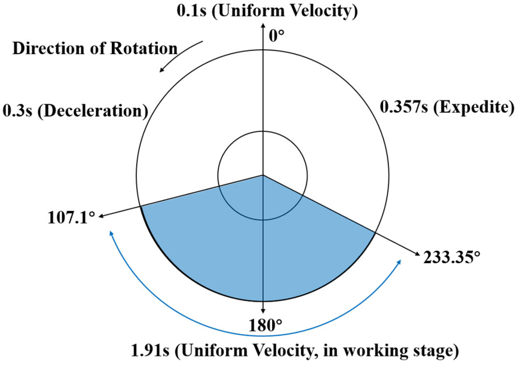
There are many factors affecting the disturbance torque of a mechanism, including motor cogging torque, friction torque, and the moment of inertia. The cogging torque and friction moment are usually small and can be minimized by designs such as motor and bearing lubrication. The disturbance moments are mainly due to mass imbalance and variable speed modes. As shown in
Figure 1, the two reflecting surfaces are mounted at an angle and have a resulting dynamic imbalance, which causes the perturbation moments. Since the scanning drive mode of the rotating mechanism is variable-speed scanning, as shown in
Figure 2, the acceleration and deceleration processes occur within a short time, which generates the perturbation moment.
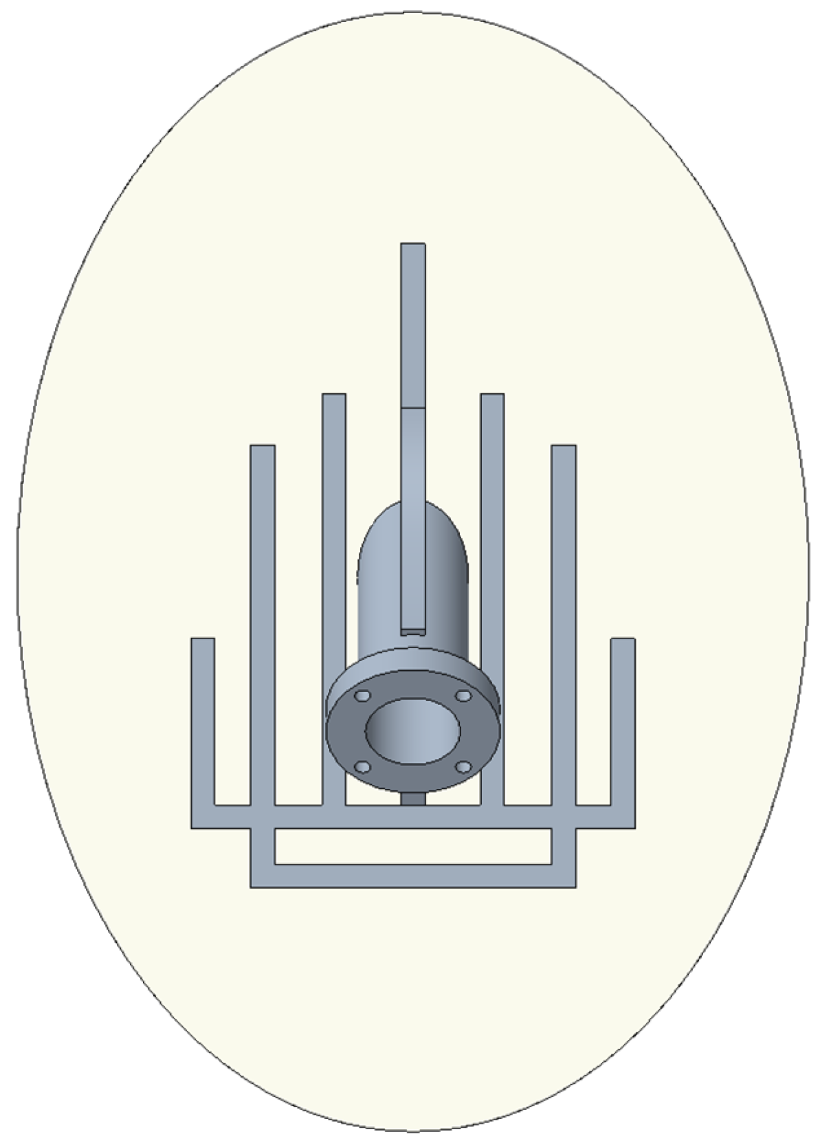
Figure 3 shows the design of the original reinforcing bar structure of the planar antenna. The rotational inertia is 1.95 × 10
−3 Kg·m² and the mass of the reinforcing bar is 210.5 g. The perturbation moment generated at uniform speed is 0.060 Nm, and the perturbation moment when the speed is varied with the maximal acceleration of 96.94 rad/s
2 is 0.1890 Nm. It can be seen in
Figure 3 that the reinforcing bar of the original structure is mainly distributed at the edge, and the scope of the reinforcing bar is much wider along the planar antenna around the circumference. This form of reinforcement layout leads to excessive rotational inertia of the planar antenna. To reduce the structural disturbance moment caused by the variable speed mode, it is necessary to reduce the rotational moment of inertia of the structure and optimize the layout and size of the reinforcement bars of the planar antenna.
3. Topology Optimization of the Planar Antenna Reinforcement Structure
3.1. Topology Optimization Mathematical Model
The structural design needs to reduce the magnitude of the rotational inertia while ensuring dynamic stiffness. When the topology optimization aims to reduce the moment of inertia of the structure, the reinforcement of the new structure will be concentrated near the rotating axis, and the dynamic stiffness of this structure is very low. Therefore, in this paper, the topology optimization is aimed at increasing the intrinsic frequency of the structure, and the size optimization is aimed at reducing the moment of inertia. In this paper, the solid isotropic material with penalization (SIMP) method is used to solve the topology optimization problem of intrinsic frequency. Compared to other methods, SIMP is a more mature and widely used topology optimization method that has been extensively applied in engineering design. The structural design variable (element density) is directly linked to the optimization problem, meaning that the topology structure is explicitly dependent on the design variables. The optimization algorithm converges well, and the sensitivity is simple and easy to calculate.
Considering the topology optimization of the intrinsic frequency, i.e., obtaining a set of design variables in the design domain to maximize the intrinsic frequency of the structure, the mathematical model can be expressed as follows:
Find
where:
represents the column vector of design variable density, the variable
represents the number of elements in the designable domain, and the relative density values of the
elements in the designable domain form
;
is the relative density of the material in the jth cell; and n is the number of finite elements. In Equation (2),
is the first-order intrinsic frequency of the structure and is the objective function. The first equation in Equation (3) represents the characteristic equation of structural vibration;
and
are the overall stiffness and mass matrices of the structure, respectively; and
is the corresponding vibration mode. The second equation in Equation (3) represents the constraints on the volume of the reinforcement;
is the volume of the designable region and
is the volume of the retained reinforcement, i.e., the volume of the portion of the reinforcing bars retained in the topology optimization results. When the retained volume is below 20% of the designable domain, the dynamic stiffness of the structure deteriorates, while exceeding 40% causes the structure’s moment of inertia to become too large. Therefore, the range of 20% to 40% is defined. The third equation in Equation (3) represents the setting of a minimum value of the design variable
to avoid singularities in the calculation.
3.2. Topology Optimization, the Finite Element Model, and Optimization Settings
The model of the planar antenna to the bearing part is selected, as shown in
Figure 4, and established as the finite element solid model for topology optimization. Among them, the planar antenna uses tetrahedral solid elements, and the rest use hexahedral elements. The three degrees of freedom on the right side of the shaft are all constrained, and the screw connection is simulated with rigid elements. The green part of the planar antenna in the figure is the designable region of the planar antenna and the rest is the non-designable region. The relative density of each element in the designable domain forms the column vector of
in Equation (1).
The design variable is the cell pseudo-density of all cells in the designable region, and the constraint is to retain the reinforcing portion as 20–40% of the volume of the designable region. Fixed constraints are applied by placing the right side of the shaft in the above figure at the bolts. The topology optimization objective is the maximum of the first-order frequency, i.e., the maximum of the dynamic stiffness. The minimum of the member size is equal to 5 mm and the maximum of the member size is equal to 17 mm.
3.3. Topology Optimization Process and Reconstruction of Reinforcement Layout
The mathematical model in
Section 1 is used for optimization, and after 14 iterations, the first-order frequency variation of the planar antenna is shown in
Figure 5. As the number of iterations increases, the frequency increases continuously. It tends to level off after the sixth time with a maximum frequency of 265 Hz.
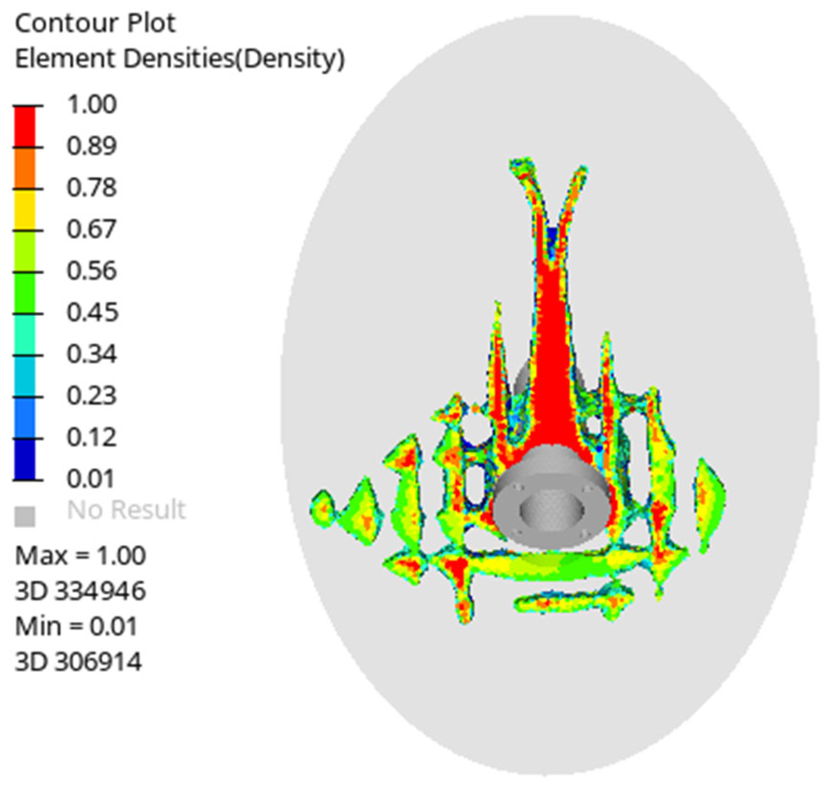
After the topology optimization calculation, the obtained results of the planar antenna reinforcement material layout are shown in
Figure 6. The topology optimization results show that the reinforcement layout in the upper and lower regions of the rotation axis is clearly visible. The red area of the reinforcement has a cell density of 1, which is the area to be retained, and the blue area has a cell density of 0, which is the non-retained area. The topology optimization results show that the reinforcements are arranged in a “palm” shape along the center. The part of the planar antenna above the shaft is similar to the structure of the cantilever beam, which is farther away from the shaft, and the distribution of the reinforcement is extended from the shaft to the upper part, which is more in line with the structural rigidity requirements.
Based on the topology optimization results, high-density areas are identified, and the layout of the new reinforcement is created, as shown in
Figure 7.
4. Size Optimization of the Planar Antenna Reinforcement Structure
In order to obtain the detailed size of the antenna reinforcement structure, such as width, thickness, height, and other design parameters, size optimization is carried out on the basis of topology optimization results. The optimization algorithm for size optimization is the method of feasible directions (MFD).
The size optimization needs to use the shell-beam element model, so it is necessary to verify the consistency between the simplified model of the shell-beam element and the refined model of the solid element first. Next, the antenna reinforcement structure is size-optimized. After sensitivity analysis of the 12 design variables for the moment of inertia and frequency, it is concluded that each variable is important. The constraints for the size optimization are RMS < 50 MPa for all cell maximum stress values and a first-order frequency > 240 Hz. The objective is to minimize the rotational inertia around the central axis. The new reinforcing structure is built based on the iteration results and compared with the original structure.
4.1. Verifying the Consistency of the Shell-Beam Cell Mesh Used for Size Optimization with the Solid Cell Mesh
Topology optimization and sizing optimization are two key stages in structural optimization, and they are usually applied at different stages of the optimal design. Topology optimization focuses on the presence or absence of material, while size optimization targets further adjustments to the thickness and width of the reinforcement in order to control the structure more finely. Size optimization targeting the thickness and width of the reinforcement requires the use of a mesh of shell-beam cells, so the error between the shell-beam cells and the solid cells is examined.
As shown in
Figure 8 below, the top figure shows the shell-beam cell model used for size optimization, and the bottom figure shows a schematic of the refined solid cell model. The different colors in figure (a) represent the reinforcing ribs at different locations. The shell-beam element model is simulated with shell elements except for the center reinforcement, and the rest of the reinforcement is simulated with beam elements. The red arrow in the middle indicates the center reinforcement. The solid element models all use hexahedral or pentahedral elements. The overall weight of the shell element model is 425.0 g, and the overall weight of the solid element model is 424.5 g. The error between the two is 0.12%, which is within the acceptable range.
The two modeling methods of the finite element model are a modal analysis of the plane antenna to obtain the first five orders of frequency values and a vibration pattern and comparison. The frequency value of each order comparison results are shown in
Table 1. The obtained modal frequency value errors of the first five orders are within 5%, and the largest gap between the fourth-order frequency errors only reached 4.96%. The model built by the shell-beam element can guarantee the accuracy of the size optimization, and the results are credible. The first five orders of the shell-beam element model and the body element model are consistent. This suggests that both the shell-beam element model and the solid element model provide similar results for the first five modes, ensuring reliability and consistency in the simulation. The fact that the shell-beam model is able to closely replicate the solid element model’s results indicates that it is a valid simplification for subsequent design steps. It can be considered that the simplified frame model using shell-beam elements can replace the solid element to complete the subsequent size optimization of the width and thickness of the reinforcement.
4.2. Optimization of the Size of the Planar Antenna Reinforcement Structure
Once the layout of the stiffeners has been determined, the choice of the size of the stiffeners also determines their effectiveness in reducing the rotational inertia of the planar antenna. In existing designs, the choice of the height and thickness of the stiffeners depends heavily on the experience of the designer. Sizing optimization is usually achieved by setting an optimization range based on experience and simulating it with finite element software to obtain the best size within that range.
The variable settings for size optimization are shown in
Table 2. There are 12 variables for size optimization. As shown in
Figure 8, they are the thickness of the center reinforcement indicated by the red arrow, the heights and thicknesses of the three reinforcement bars on both sides of the center reinforcement, the heights and thicknesses of the two reinforcement bars perpendicular to the center reinforcement, and the thicknesses of the planar antenna base plate. The step size of each variable is 0.5 mm.
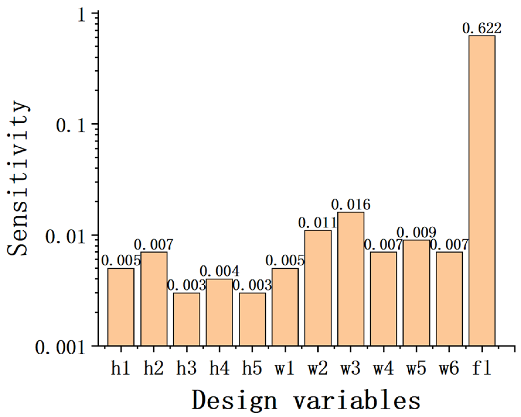
After the sensitivity analysis calculation, the sensitivity results of the design variables are finally obtained. The sensitivity analysis results of each design variable on the moment of inertia are shown in
Figure 9 and the sensitivity analysis results of the frequency are shown in
Figure 10. The variable fl denotes the thickness of the base plate, which is a design variable. As can be seen from the sensitivity analysis results, the thickness of the base plate has the greatest influence on the moment of inertia and frequency, and the influence of the remaining variables on the moment of inertia and frequency is slightly lower; however, each variable is very important, and the combined influence will be larger.
The constraints of size optimization are the RMS of the maximum stress value of all elements < 50 Mpa and first-order frequencies > 240 Hz, and the objective is to minimize the rotational inertia around the central axis. The mathematical model for size optimization is shown below:
Find
where
represents the column vector of 12 design variables and
is the thickness of the jth variable.
in Equation (5) is the rotational inertia of the structure around the central axis, which is the objective function of optimization.
in Equation (6) is the first-order intrinsic frequency of the structure.
is the lower limit of the ith thickness and
is the upper limit of the ith thickness.
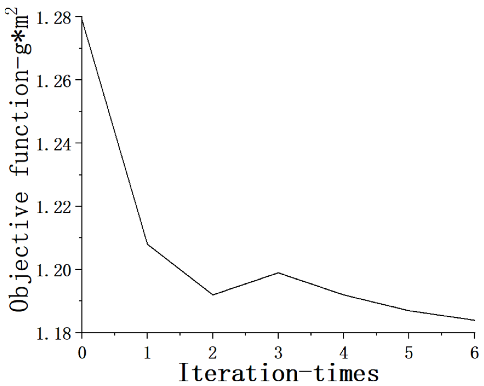
As shown in
Figure 11 below, after six iterations, the rotational inertia is minimized to 1.18 × 10
−3 Kg·m
2.
Based on the iteration results, the reinforcement structure shown in
Figure 12 below is established. Since the goal is to reduce the rotational inertia, the thickness and height of the reinforcement near the center are higher than the reinforcement away from the center. Unlike topology optimization, size optimization effectively reduces rotational inertia by precisely adjusting the dimensions of the reinforcement ribs, especially those near the rotational axis. The mass of the reinforcing bar after size optimization is 155.9 g, which is 26% less than the original structure; the rotational inertia is 39% less than the original structure. The disturbance moment generated during variable-speed motion is 0.1144 Nm, which is 39% less than the original structure, while the disturbance moment generated during uniform rotation of the antenna is 0.0290 Nm, which is 52% less than the original structure due to the reduction of the amount of dynamic inequality. The rotational inertia of the new structure is lower than that of the original structure, which is helpful for reducing the disturbance moment of the structure and helps to improve the motion control precision and stability of the system, which is suitable for scenarios that require high-precision rotation. It is conducive to the realization of high-stability attitude control of the satellite.
4.3. Comparison Between the Size-Optimized and Original Structures
The modal analysis of the optimized structure and the original structure is performed separately, and the first five orders of modal frequency values and vibration shapes are extracted and compared. The results of the comparison of the frequency values of each order are shown in
Table 3.
As shown in
Figure 13 below, the left column shows the first- to fifth-order vibration patterns of the original structure, and the right column shows the first- through to fifth-order vibration patterns of the new structure. The red area represents the vibrating region of the structure, while the blue area represents the non-vibrating region of the structure.
Comparing the first- to fifth-order vibration patterns of the original structure and the new structure, it can be concluded that the first three orders are mainly the vibration of the front side of the rotating shaft, and the dynamic stiffness of the new structure in the front side of the rotating shaft is better than that of the original structure, so the frequency of the new structure is higher than that of the original structure in the first three orders. From the fourth order onwards, the higher-order vibration patterns are all at the edges. The ribs of the original structure are mainly distributed at the edges with a wider range, and the ribs of the new structure are all concentrated at the rotation axis.
The dynamic stiffness of the new structure after topology optimization is higher than that of the original structure, with less rotational inertia and less mass of reinforcement. The key here is that optimizing the placement of reinforcement close to the rotational axis, rather than spreading it out along the edges, reduces unnecessary mass while maintaining or improving performance. This design change enhances the overall structural efficiency, which is critical for reducing torque disturbances and improving the satellite’s dynamic behavior. The reinforcement of the new structure is distributed near the center of the rotating axis, and the reinforcement form of the original structure that surrounds the antenna along the plane is not the optimal layout.
5. Conclusions
This paper mainly introduces the optimization design method of the reinforcement of the scanning drive mechanism of the star-carried microwave probe antenna. The antenna scanning drive mechanism has two motion modes, uniform speed and variable speed, and the structural form of the reflecting surface leads to a large perturbation moment in the two scanning modes, which affects the high-precision attitude positioning of the satellite. In order to solve this problem, this article proposes an integrated design method that combines topology optimization and size optimization to reconstruct the layout and size of the reinforcement ribs, obtaining the following conclusions:
1. The topology optimization takes the maximum structural dynamic stiffness as the optimization objective, and a more reasonable lightweight antenna reflective surface backing rib structure can be obtained.
2. On the basis of topology optimization, size optimization is carried out. The size optimization takes the minimum rotational moment of inertia as the optimization objective to reduce the influence of moment disturbance. The mass of the reinforcing bar after the size optimization is 155.9 g, which is 26% less than the original structure. The rotational inertia is reduced by 39% compared to the original structure. The perturbation moment in uniform rotation is reduced by 52%, and in variable-speed motion, the perturbation moment is reduced by 39% compared to the original structure. All of these are below the 0.05 N requirement for the spaceborne microwave probe antenna. These reductions significantly enhance the system’s performance in high-precision satellite operations, reducing disturbances and improving accuracy.
3. The combination of topology optimization and size optimization can lead to a structure with better mechanical properties, which can be extended to the structure optimization design of all kinds of antennas. The topology optimization ensures the dynamic stiffness of the structure, and the size optimization reduces the rotational inertia of the structure and helps to improve the motion control precision and stability of the system, which is suitable for scenarios that require high-precision rotation. It is conducive to the realization of the high-stability attitude control of satellites. This integrated method offers a more systematic approach to optimizing both performance and mass, moving beyond traditional engineering experience-based approaches.
Comparing the first- through fifth-order vibration modes of the original structure and the new structure, it is evident that the first three modes primarily involve vibrations on the front side of the rotating shaft. The dynamic stiffness of the new structure on the front side of the rotating shaft is superior to that of the original structure, resulting in higher frequencies for the new structure in the first three modes. Starting from the fourth mode, the higher-order vibration modes are localized at the edges. The ribs of the original structure are predominantly distributed at the edges with a broader coverage, whereas the ribs of the new structure are concentrated around the rotation axis.
The dynamic stiffness of the new structure, following topology optimization, is greater than that of the original structure, with reduced rotational inertia and lower reinforcement mass. The reinforcement of the new structure is positioned near the center of the rotating axis, and the reinforcement layout of the original structure, which encircles the antenna along the plane, is not the optimal configuration.
Author Contributions
Conceptualization, D.W. and W.F.; methodology, D.W. and W.F.; software, D.W., C.Y. and P.K.; validation, D.W. and W.F.; formal analysis, D.W.; investigation, D.W. and C.Y.; resources, J.H. and S.Z.; data curation, D.W. and P.K.; writing—original draft preparation, D.W.; writing—review and editing, W.F. and P.K.; visualization, D.W.; supervision, W.F.; project administration, J.H. and S.Z.; funding acquisition, W.F. All authors have read and agreed to the published version of the manuscript.
Funding
This research was funded by the Chinese Academy of Sciences Technical Support Talent Program, grant number 2024000074.
Institutional Review Board Statement
Not applicable.
Informed Consent Statement
Not applicable.
Data Availability Statement
Data underlying the results presented in this paper are not publicly available at this time but may be obtained from the authors upon reasonable request.
Acknowledgments
I would like to acknowledge the administrative and technical support provided by the National Space Science Center (NSSC).
Conflicts of Interest
The authors declare no conflicts of interest.
References
- He, J.Y.; Zhang, S.W.; Wang, Z.Z.; Zhang, Y. Prospects for Microwave Atmospheric Sounding of the New Generation of Fengyun Meteorological Satellites. Chin. J. Space Sci. 2023, 43, 1025–1035. [Google Scholar] [CrossRef]
- Ying, H.J.; Wei, Z.S.; Yu, Z. The Primary Design of Advanced Ground-Based Atmospheric Microwave Sounder and Retrieval of Physical Parameters. Remote Sens. Technol. Appl. 2010, 112, 236–246. [Google Scholar] [CrossRef]
- Zhang, S.W.; Li, J.; Jiang, J.S.; Sun, M.H.; Wang, Z.Z. Design and Development of Microwave Humidity Sounder for FY-3 Meteorological Satellite. J. Remote Sens-Prc. 2008, 2, 9. [Google Scholar] [CrossRef]
- Zhang, S.W.; Wang, Z.Z.; Sun, M.H.; He, B.Y.; Jiang, J.S. The design and development of advanced microwave atmospheric counder onboard FY-3 satellite. China Eng. Sci. 2013, 15, 81–87. [Google Scholar] [CrossRef]
- Li, W.; Zhang, M.; Zhu, D.; Liu, H. Simulation and Optimization of Composite Parabolic Antenna With Stiffening Ribs. Aerosp. Mater. Technol. 2015, 45, 27–31. [Google Scholar]
- Zhou, T.; Liang, Y.M.; Wu, W.P.; Wu, X.; Ye, Z.J.; Dong, B. Lightweight Design of Spaceborne CFRP Rigid Antenna Reflector. Shanghai Aerospace 2022, 39, 137–149. [Google Scholar] [CrossRef]
- Liu, J.K.; Ma, Y.S. A survey of manufacturing oriented topology optimization methods. Adv. Eng. Softw. 2016, 100, 161–175. [Google Scholar] [CrossRef]
- Dangal, B.; Jung, S. The Impact of Additive Manufacturing Constraints and Design Objectives on Structural Topology Optimization. Appl. Sci. 2023, 13, 10161. [Google Scholar] [CrossRef]
- Meng, L.; Zhang, W.; Quan, D.; Shi, G.; Tang, L.; Hou, Y.; Breitkopf, P.; Zhu, J.; Gao, T. From topology optimization design to additive manufacturing: Today’s success and tomorrow’s roadmap. Arch. Comput. Methods Eng. 2021, 28, 269. [Google Scholar] [CrossRef]
- Delyová, I.; Frankovský, P.; Bocko, J.; Trebuňa, P.; Živčák, J.; Schürger, B.; Janigová, S. Sizing and Topology Optimization of Trusses Using Genetic Algorithm. Materials 2021, 14, 715. [Google Scholar] [CrossRef]
- Zhu, B.L.; Zhang, X.M.; Zhang, H.C.; Liang, J.W.; Zang, H.Y.; Li, H.; Wang, R.X. Design of compliant mechanisms using continuum topology optimization: A review. Mech. Mach. Theory 2020, 143, 103622. [Google Scholar] [CrossRef]
- Lei, Y.; Lu, D.; Mu, X.; Li, L.; Chen, C. Modelling and Mitigation of Dual-Axis Antenna Induced Disturbances on Spacecraft. In Proceedings of the 38th Chinese Control Conference, Guangzhou, China, 27–30 July 2019; pp. 3202–3207. [Google Scholar]
- Montemurro, M.; Refai, K. A Topology Optimization Method Based on Non-Uniform Rational Basis Spline Hyper-Surfaces for Heat Conduction Problems. Symmetry 2021, 13, 888. [Google Scholar] [CrossRef]
- Yu, D.Y.; Wang, G.Y.; Zheng, Z.M.Y. Modelling and Simulation of Disturbance Torque Generated by Solar Array Driven by Permanent Magnet Synchronous Motor. J. Aeronaut 2019, 40, 742–747. [Google Scholar]
- Sleesongsom, S.; Kumar, S.; Bureerat, S. Multi-Objective Reliability-Based Partial Topology Optimization of a Composite Aircraft Wing. Symmetry 2023, 15, 305. [Google Scholar] [CrossRef]
- Niu, B.; Yan, J.; Mao, Y.; Liu, H. Collaborative Design Optimization of Damping Layers and Stiffener Layout of Thin-walled Stiffened Plate Structures for Dynamics Performances. China Mech. Eng. 2021, 32, 9. [Google Scholar]
- Chen, T.Y.; Wang, C.B. Topological and sizing optimization of reinforced ribs for a machining centre. Eng. Optim. 2008, 40, 33–45. [Google Scholar] [CrossRef]
- Wang, J.P.; Chang, S.; Liu, G.; Liu, L.; Wu, L.Y. Optimal rib layout design for noise reduction based on topology optimization and acoustic contribution analysis. Struct. Multidiscip. Optim. 2017, 56, 1093–1108. [Google Scholar] [CrossRef]
- Wang, P.P.; Niu, B.H.; Ai, Y.Q.; Wang, S.M. Dynamic balancing design simulation and test for HY-2A satellite microwave radiometer. J. Vibr. Shock 2016, 35, 6. [Google Scholar] [CrossRef]
- Li, Y.X.; Sun, Y.X.; Li, S.Y.; Wu, F.H. Lightweight design of reinforcing structure of space reflector based on the multi-objective optimization theory. J. Mech. Des. 2019, 36, 35–39. [Google Scholar] [CrossRef]
- Ayari, L.; Kubitschek, M.; Ashton, G.; Johnston, S.; Debevec, D.; Newell, D.; Pellicciotti, J. GMI Instrument Spin Balance Method, Optimization, Calibration, and Test. In Proceedings of the 42nd Aerospace Mechanisms Symposium, NASA Goddard Space Flight Center, Baltimore, MD, USA, 14 May 2014; pp. 1–14. [Google Scholar]
- Yang, K.; Chen, B.; Jia, Q.; Gu, Z. Effects of driving model and rotational speed on disturbance characteristics of spaceborne antenna. Shanghai Aerospace 2023, 6, 1–10. [Google Scholar] [CrossRef]
- Zhou, Y.; Li, Z.J.; Ma, C.; Wang, X.N. Reduced torque ripple for rotational load with high inertia of HY-2A satellite. Strat. Study CAE 2014, 16, 43–49. [Google Scholar] [CrossRef]
- Lu, D.N.; Guo, C.Y.; Wang, S.Y.; Chen, C. A disturbance mitigation method for moving appendages on spacecraft. Chin. Space Sci. Technol. 2020, 40, 8. [Google Scholar] [CrossRef]
| Disclaimer/Publisher’s Note: The statements, opinions and data contained in all publications are solely those of the individual author(s) and contributor(s) and not of MDPI and/or the editor(s). MDPI and/or the editor(s) disclaim responsibility for any injury to people or property resulting from any ideas, methods, instructions or products referred to in the content. |
© 2025 by the authors. Licensee MDPI, Basel, Switzerland. This article is an open access article distributed under the terms and conditions of the Creative Commons Attribution (CC BY) license (https://creativecommons.org/licenses/by/4.0/).


 ,
, 


