Article

Characterization of NiCrAlY Layers Deposited on 310H Alloy Using the EB-PVD Method After Oxidation in Water at High Temperature and Pressure

by
Florentina Golgovici
1,
Aurelia-Elena Tudose
1,2,
Laurențiu Florin Mosinoiu
3 and
Ioana Demetrescu
1,4,*
1
Department of General Chemistry, National University of Science and Technology Politehnica Bucharest, Splaiul Independentei Street, No. 313, 060042 Bucharest, Romania
2
Institute for Nuclear Research Pitesti, Campului Street, No. 1, P.O. Box 78, 115400 Mioveni, Romania
3
National Research & Development Institute for Non-Ferrous and Rare Metals, 102 Bulevardul Biruinței, 077145 Pantelimon, Romania
4
Academy of Romanian Scientists, 3 Ilfov, 050094 Bucharest, Romania
*
Author to whom correspondence should be addressed.
Appl. Sci. 2025, 15(5), 2361; https://doi.org/10.3390/app15052361
Submission received: 24 December 2024 / Revised: 8 February 2025 / Accepted: 20 February 2025 / Published: 22 February 2025
(This article belongs to the Section Chemical and Molecular Sciences)

Abstract

:

Featured Application

As mentioned in the title, this paper is dedicated to investigating an advanced procedure of the EB-PVD deposition method to increase the performance of 310H alloys used in aggressive pressure and temperature conditions. The proposed coating is NiCrAlY and the potential application is for cleaner nuclear energy, which is the material being used for generation IV SCW reactors.

Abstract

In this paper, the oxidation behavior of the 310H alloy coated with NiCrAlY using the EB-PVD method is studied after exposure to water at a high temperature and pressure (550 °C and 25 MPa) for different periods (720 h, 1440 h, and 2160 h). The Electron Beam Physical Vapor Deposition (EB-PVD) method was used to obtain the NiCrAlY coating. After testing, the coating performance was carried out by gravimetric analysis, grazing incidence X-ray diffraction (GIXRD), scanning electron microscopy (SEM), electrochemical impedance spectroscopy (EIS), and the linear polarization method. GIXRD analysis highlighted the presence of chromium oxide (Cr2O3) and the Corundum phase (Al2O3) on the surface of the oxidized NiCrAlY-coated 310H samples. On the surface of the 310H alloy, the existence of the NiCrAlY coating and of the oxide film generated during oxidation are evident according to the EIS spectra, which show two capacitive semicircles in the Nyquist diagram. Furthermore, an increase in diameter semicircles with the oxidation time increasing was observed in the Nyquist diagram. Very low corrosion rates of 4.8 × 10⁻⁵ mm × year−1, which were observed for oxidization for 2160 h NiCrAlY-coated samples, indicated that the oxide films are more protective and provide better corrosion resistance, which is also evidenced by the EIS analysis. Considering the obtained results, a significant relationship between the electrochemical technique, scanning electron microscopy, and gravimetric analysis was established.

1. Introduction

Today, considering the global energy crisis as well as climate change, alternatives are being sought worldwide to decrease the dependence on fossil fuels; thus, a particular interest can be observed in nuclear energy [1]. In this context, Gen IV nuclear reactors present a significant global challenge as a sustainable and economical mode of energy production [2]. Compared to current nuclear reactor systems, the new Gen IV reactors operate in more severe conditions and require new materials for the new performance in an aggressive environment. One of the six innovative nuclear fission reactor concepts is the Supercritical Water-Cooled Reactor (SCWR), which uses water above its critical thermodynamic point (374 °C, 22.1 MPa). In such an environment, the structural materials used in conventional nuclear reactors can no longer meet the operating requirements, and new selections were proposed as the material substrates and their coatings [3]. The suggested substrates come from various alloy classes, including Ni-based alloys (IN718, IN625), austenitic stainless steels (304, 304L, 316, 316L, 310), and ferrite–martensitic steels (HT-9, T91, T92, and HCM12A). Following heat treatment and exposure to high temperatures, the nonmagnetic austenitic stainless steel varieties, known as the chromium–nickel 300-series and the chromium–nickel–manganese 200-series steels, demonstrate exceptional mechanical and corrosion resistance [4].
Due to their mechanical and corrosion resistance properties, as well as their performance against radiation, austenitic stainless steels [5] have attracted special interest for applications in higher temperatures and pressures. With a crystalline structure of the FCC type, the 310H type is a 300-series chromium–nickel austenitic stainless steel material that was developed for utilization at temperatures ranging from 800 °C to 900° C. It combines exceptional high-temperature qualities with resistance to creep, weldability, and strong ductility.
To improve corrosion resistance, existing alloys can be modified by applying thin protective ceramic or metallic layers on the surface using different surface modification techniques. Currently, there are several techniques for thin layers on metal surface deposition, which are as follows: physical vapor deposition (PVD) [6,7] and chemical vapor deposition (CVD). An early technology was EB-PVD, which is still in use. The coatings obtained via such procedures have high density, remarkable oxidation resistance, and a strong bonding force [8,9,10].
For the EB-PVD technology, alloy targets are mostly used, and the coating composition is affected by the target content. When a high-energy ion beam bombards the target, after melting, sublimation, and evaporation, the deposition of the target takes place. Since each element’s saturated vapor pressure is different, the coating composition on the surface sample will change.
When placed in a thin, homogeneous layer, vapor-deposited coatings are dense. These types of coatings result in a decrease in the quantity of gas or moisture that can pass through the film. Consequently, these coatings are perfect for corrosion reduction in a nuclear environment. This applies to Generation IV reactors, such as SCW-type or liquid metal-cooled reactors, as well as existing LWR reactors (BWR, PWR) and CANDU reactors [11,12].
In this paper, 310H stainless steel has been selected for testing because the tests carried out so far, as well as the data from the literature, proved that this type of steel has a high oxidation resistance in water at high temperatures and pressures, while remaining susceptible to intergranular corrosion [13,14,15] and sigma phase precipitation when exposed to aggressive conditions like 550 °C and 25 MPa for a longer period of time [16]. Therefore, applying protective ceramic or metallic layers on the surface of this alloy has proven to be one of the ways to improve corrosion resistance.
Ceramic materials such as nitrides, carbides, silicones, transition metal oxides, and metallic materials—such as MCrAlY (M = Ni, NiCo, CoNi, or Fe)—show good resistance in corrosive environments, and are thus recommended for applications in water at supercritical temperatures. NiCrAlY-based coatings, widely used as independent layers or bond layers in TBCs (thermal barrier coatings), are selected in this paper based on their good adhesion, high modulus, high strength, and good oxidation resistance [17,18,19]. The development of a corrosion-resistant layer (Cr2O3, and Al2O3) on the material’s surface, which shields the deposited layer and the base material (substrate), is what gives the material its high oxidation resistance [20]. Additionally, dense layers rich in α-Al2O3-forming serve as a protective barrier, thus effectively preventing the diffusion-controlled oxidation process and rapid deterioration of the coated superalloys [21].
In recent years, only a few authors have studied the oxidation behavior of coated austenitic alloys under extreme conditions [22], even though knowledge of the oxidation of austenitic steel 316 L at high temperatures [23] is more present in the literature [24,25,26]. An example of this is the corrosion behavior of CrNx-coated 310H SS before and after exposure to water under supercritical pressure and temperature (550 °C and 25 MPa) for up to 2160 h [22,27,28].
The present paper aims to study the corrosion behavior of the NiCrAlY-coated 310H alloy in thermally degassed demineralized water (2 ppm O2) at a temperature of 550 °C and a pressure of 25 MPa for up to 2160 h. After oxidation, all tested samples were characterized by the following various methods: gravimetric analysis, grazing incidence X-ray diffraction (GIXRD), or scanning electron microscopy (SEM). The corrosion susceptibility has been assessed using the following two electrochemical techniques: linear potentiodynamic polarization and electrochemical impedance spectroscopy (EIS). The motivation for choosing such an investigation is based on the fact that the selected 310H alloy coating was not sufficiently studied at high temperatures despite its remarkable behavior. It is also crucial to mention the novel character of this article, which has a detailed electrochemical investigation of NiCrAlY film on 310 alloys studied in aggressive temperature and pressure conditions. The electrochemical aspect has not been studied until now. The original character of this article is not only the fabrication, but also the characterization for a longer time. All such aspects are important for us to gain more knowledge about nuclear material candidates for generation IV reactors.

2. Materials and Methods

2.1. Coating Material
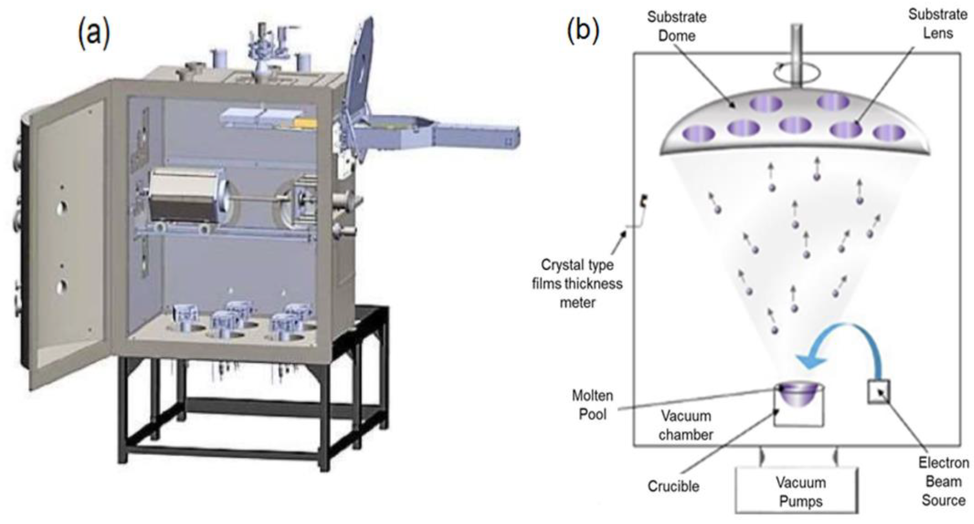
Using the Electron Beam Physical Vapor Deposition (EB-PVD) technique, NiCrAlY layers with a thickness of approximately 1.5 µm were applied to the surface of 310H stainless steel samples that were bought from Outokumpu Stainless AB Company (Degerfors, Sweden) and cut to dimensions of 25 mm × 15 mm × 2 mm. After being hot rolled and heated to 1100 degrees Celsius, the plate was quenched with water. Table 1 lists this material’s chemical makeup [29] in weight percentage (wt. %).
The samples were provided with a hole 3 mm in diameter at one end for mounting on the autoclave holder. The samples were mechanically sanded with abrasive paper of various granulations (#120, #240, #400, and #600 µm) before deposition, after which they were exposed to the acetone ultrasound for 30 min. The samples were ultrasonically cleaned, dried, and then weighed with an analytical balance.
The present coating selection is based on the investigation from a previous paper [30], which established such coatings as viable candidates for protective coatings for high-temperature and high-pressure work, both of which were the basis for this coating’s selection. Table 2 [31] shows the chemical composition of NiCrAlY.

2.2. Coating Method

This work examines the deposition of NiCrAlY coatings, which have been produced by the Electron Beam Physical Vapor Deposition (EB-PVD) technique. The installation used for the deposition of NiCrAlY is presented in Figure 1a, and the evaporation process is schematically represented in Figure 1b [32,33]. The coating method used a TORR 5X300EB-45 kW electron flux deposition system (Thermionics NW, Auburn, WA, USA). The coating composition is changed compared to the target content by considering the different vapor pressures of each element after the electron beam bombarding and evaporation process. The deposition parameters used for the deposition of these layers by the EB-PVD method are presented in Table 3.

2.3. Testing Method

All samples were tested in static thermally degassed demineralized water (2 ppm O2) at a temperature of 550 °C and a pressure of 25 MPa, for up to 2880 h of exposure, and with the autoclave stopping every 720 h. The pH of the testing solution was about 6.1 ÷ 6.3 and the water conductivity at 25 °C was 0.2 ÷ 0.25 μS cm−1. At regular intervals, all samples were taken out of the autoclave to weigh the specimens following drying and rinsing. The morphological and functional characterization of the samples, as well as the electrochemical tests, were carried out. The autoclave solution was changed by adding a new one following each inspection. A balance with an accuracy of 1 × 10⁻⁵ g was used to calculate weight increases brought on by oxidation. Determination of the mass variation required knowledge of the starting weight and the weight obtained after oxidation.
The oxidation rates were calculated as follows, according to Equation (1) [34]:
v = m d × 0.0365 ρ
where md is the mass variation per unit area S and exposure time t of the sample, expressed in mg × dm−2 × day−1, and ρ is the density. The unit of measurement for the oxidation rate is mm × year−1. According to the XRD results, a mixture of Al2O3 and Cr2O3 is formed on the coated 310H stainless steel surface when exposed to water at high temperatures and pressures [35].

2.3.1. Structural and Morphological Characterization

GIXRD and SEM examination were used to examine the morphological and structural characteristics of the surfaces of the NiCrAlY-coated 310H stainless steel samples both before and after they were exposed to supercritical water.
GIXRD analysis was conducted using an X’Pert PRO MPD Diffractometer (PANalytical B. V., Almelo, The Netherlands), wherein the structure and the chemical composition of samples before and after oxidation were investigated. The GIXRD patterns were made in a θ–2θ geometry using CuKα radiation (λ = 1.5406 Å) at a grazing angle of 5° in the 10–95° range. The X’Pert Data Collector software (v.2.2) was used to establish parameters for experimental study. The acquired X-ray scans were manually analyzed by comparing them to the reference patterns from the International Center for Diffraction Data (ICDD) (PDF-4+) database. The morphologies of all coated sample surfaces before and after oxidation were investigated by SEM using a TESCAN VEGA II LMU microscope (Tescan Orsay Holding, Brno-Kohoutovice, Czech Republic).

2.3.2. Electrochemical Tests

Two electrochemical methods, linear potentiodynamic polarization and electrochemical impedance spectroscopy (EIS), have been used to evaluate the corrosion susceptibility.
An electrochemical system, PARSTAT 2273 potentiostat/galvanostat (Princeton Applied Research, AMETEK, Oak Ridge, TN, USA), was used for all electrochemical measurements. Electrochemical studies were conducted using a traditional three-electrode electrochemical cell, which consists of an auxiliary electrode (graphite rod), a saturated calomel reference electrode (SCE), and a working electrode (the NiCrAlY-coated 310H SS sample). The characteristics of the oxide layer were unaffected by the electrochemical tests, which were conducted at room temperature (22 ± 2 °C) in a chemically inert solution with a pH of 7.7–7.8 (0.05 M boric acid with 0.001 M borax solution). Nyquist and Bode diagrams were drawn using the impedance spectra, acquired at open-circuit potential (OCP) with an ac amplitude of 10 mV in the frequency range from 100 kHz to 100 mHz, following OCP stabilization [36]. To perform a quantitative analysis, the experimental EIS data were simulated using analogous electrical circuits and Zview 2.90c software (Scribner Associates Inc., Southern Pines, NC, USA).
To observe the corrosion behavior of the samples, the potentiodynamic polarization plots were recorded in a potential range of −0.250 V vs. OCP up to +1.0 V. The scan rate was 0.5 mV/s. Based on the polarization plots, using the Tafel slope method and the polarization resistance (Rp) method, the main electrochemical parameters that were specific to the corrosion process were determined, as follows: corrosion potential (Ecorr), corrosion rate (vcorr), corrosion current density (icorr), and polarization resistance (Rp). Based on these parameters, the oxide protection efficiency (Pi) and porosity coefficient (P) were calculated as well using Equations (2) and (3) [37,38].
P i % = 1 i c o r r i c o r r 0 × 100
where
icorr is the corrosion current density of the deposited layers;
i corr 0 is the corrosion current density of the substrate.
P % = R p s R p × 10 Δ E c o r r β a
where
P is the total porosity of the deposited layer;
Rps is the polarization resistance of the uncoated substrate;
Rp is the polarization resistance of the coated sample;
βa is the anodic Tafel slope;
∆Ecorr is the difference between the corrosion potentials of the coating and the substrate.

3. Results and Discussion

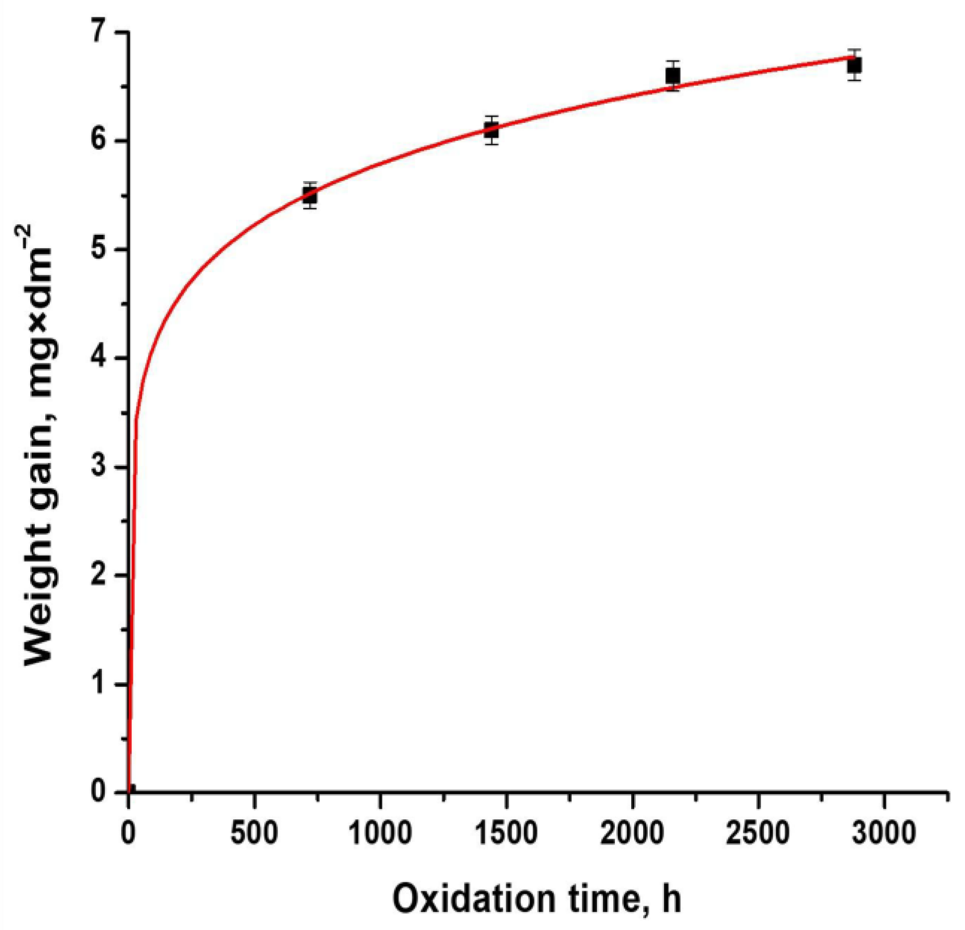
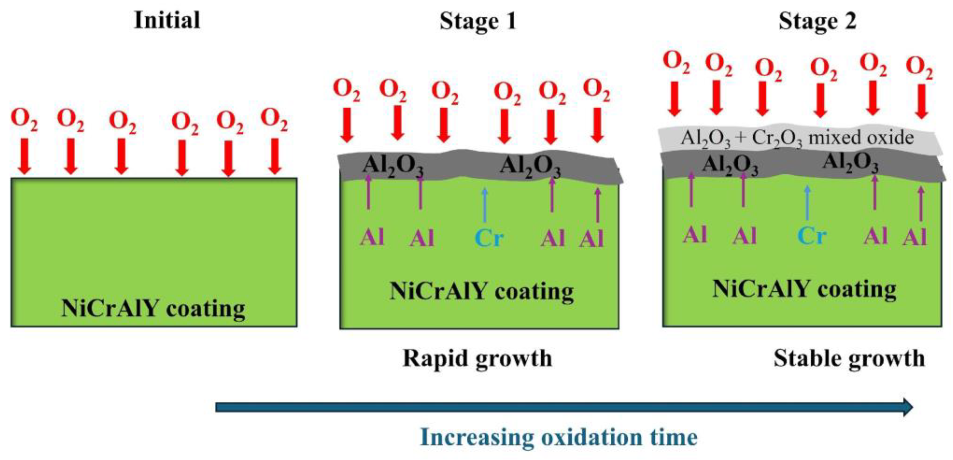
3.1. Oxidation Kinetics

To carry out the gravimetric analysis, every 720 h of oxidation in water at a temperature of 550 °C and a pressure of 25 Mpa, three stainless steel samples coated with NiCrAlY were taken out of the autoclave, after which they were washed, dried, and weighed with an accuracy of 1 × 10⁻⁵ g, using the KERN analytical balance. Based on the mass variation, oxidation kinetics were also determined for all coated samples after testing them in water at high temperatures, as can be seen in Figure 2. The oxidation kinetics are represented by the mass variation as a function of the oxidation time.
Gravimetric analysis reveals that all tested samples gained weight over time due to oxidation.
The mass values determined by weighing in the case of the tested samples fell between 5.36065 mg × dm−2 and 7.14577 mg × dm−2. The oxidation kinetics (Figure 2) were also determined for all tested samples using the obtained mass gains values.
The oxidation process is described as follows by the kinetic Equation (4):
Δ m s = k t n
where
Δm is the mass gain, [mg];
s is the sample surface, [dm2];
k is the rate constant of the oxidation reaction;
t is the exposure time, [h];
n is the time constant.
By fitting Equation (4) through non-linear regression, the oxidation constant, k, and the time constant, n, were obtained and included in Table 4. The value of the correlation coefficient (R2 = 0.9991) indicates that the experimental data of the oxidation of 310H samples coated with NiCrAlY by the EB-PVD method fit very well.
In our previous studies [39], the substrate was tested under the same conditions and for the same periods of time. The oxidation process was characterized by parabolic kinetics because n = 0.564. This fact indicates that oxidation is controlled by the diffusion of metal ions and oxygen through a generally protective oxide.
Average values of oxide thicknesses (µm) and oxidation rates (µm × year−1) calculated from mass measurements for 310H stainless steel samples coated with NiCrAlY and oxidized for 720 h, 1440 h, 2160 h, and 2880 h in water at 550 °C and 25 Mpa are graphically shown in Figure 3.
Figure 3 shows that as the oxidation period increased, the oxide thicknesses increased, and the corrosion rates decreased. The lowest value of the corrosion rate of 0.27 μm × year−1, obtained for a coated sample and oxidized for the longest period of time, shows a better corrosion resistance.
It should be mentioned that compared to the data obtained by electron microscopy, where layer thicknesses are determined only on the areas visualized under the microscope (the samples may have a thicker or thinner layer in other areas), global layer thicknesses were calculated by gravimetric analysis.

3.2. Morphological and Structural Characterization of the Oxides Formed Following Oxidation

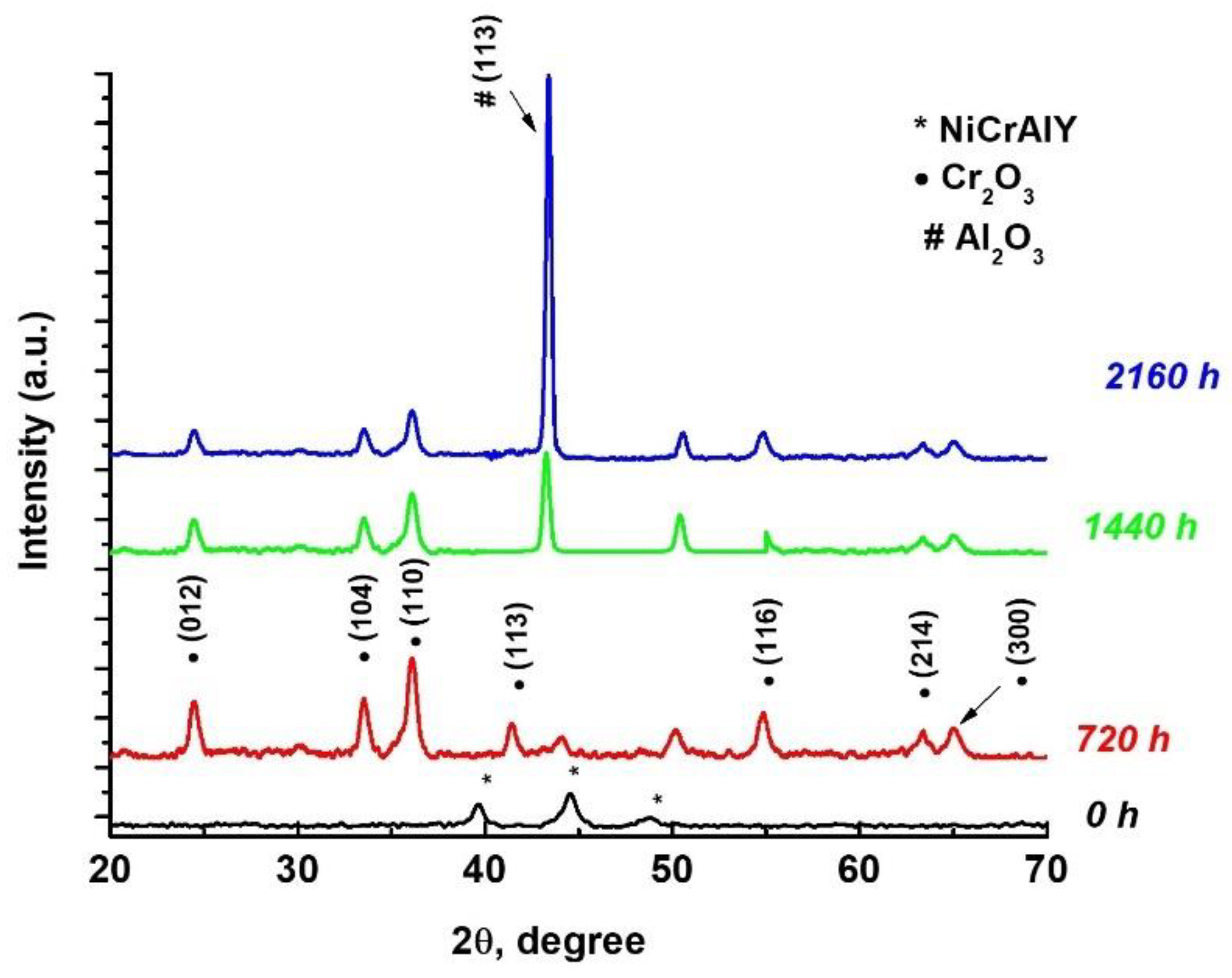
3.2.1. Grazing Incidence X-Ray Diffraction (GIXRD)

Figure 4 shows the X-ray diffraction spectra obtained for the 310H substrates coated with a layer of NiCrAlY before and after exposure for 720 h, 1440 h, and 2160 h in water at 550 °C and 25 Mpa. The spectra were obtained at the incidence angle of 50.
The diffractograms presented in Figure 4 show the changes induced in the composition of the NiCrAlY layer following the sample oxidation in the environment simulating the conditions in an SCW reactor. Thus, in the figure above, on the surface of the coated and unoxidized samples, the NiCrAlY phase was identified as a deposited layer, while on the surface of all oxidized samples, chromium oxide (Cr2O3) and the Corundum phase (Al2O3) were identified. The diffraction spectrum of Cr2O3 (PDF card no. 00-38-1479) shows some diffraction peaks, at 24.5°, 33.6°, 36.2°, 41.9°, 54.3°, 63.5°, and 65.1° 2 thetas, corresponding to (012), (104), (110), (113), (116), (214), and (300) planes, respectively. The presence of the Eskolite phase of the Cr2O3 structure, where the peaks are attributed to the rhombohedral structure, is confirmed by Tsegay et al. [38]. The presence of the Corundum phase (PDF card no. 00-46-1212) is highlighted by the appearance of a high peak at 43.3°, corresponding to (113), which increases with increasing oxidation time.

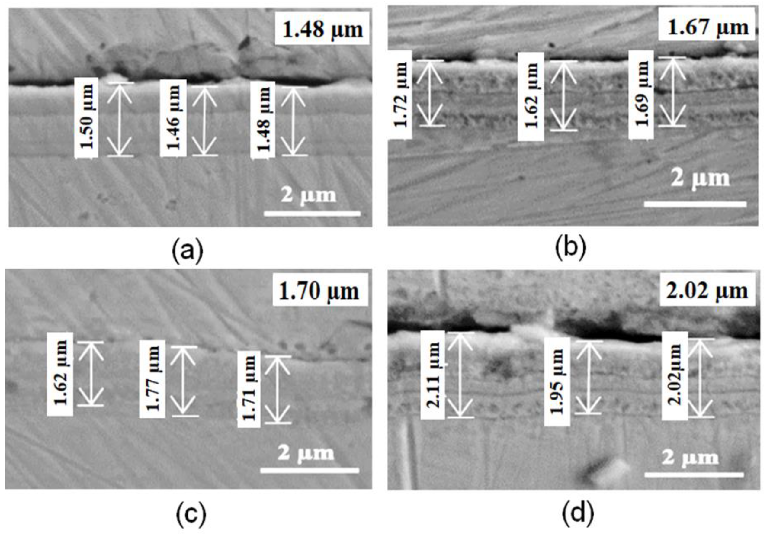
3.2.2. Scanning Electron Microscopy (SEM)

The morphologies of coated samples before and after oxidation for various periods of time in water at a supercritical temperature are displayed by SEM examination.
Figure 5a–d shows the SEM images at magnifications of 10 kx and 50 kx obtained for NiCrAlY-coated samples before and after 720 h, 1440 h, and 2160 h of oxidation in water at 550 °C and 25 Mpa.
To measure the thickness of the deposited layer, SEM in cross-section analyses were also carried out (Figure 6a–d).
From the SEM micrographs shown in Figure 6a, we can see that the deposition of an initial layer of NiCrAlY is not very continuous, and its cross-section thickness, measured by SEM, was approximately 1.48 μm. The deposition layer is granular, without visible defects (pores, cracks).
With an increasing oxidation time, a slight increase in layer thickness is observed from 1.48 µm to 2.02 µm (the case of samples coated and oxidized 2160 h), which means that a thin, compact, and fairly uniform oxide layer has been deposited on the sample surfaces (see Figure 5b–d and Figure 6b–d). A similar behavior, with comparable values of the oxide layer, was also obtained by other authors who studied the behavior at 1100 °C of some NiCrAlY coatings obtained by different methods, such as cathode arc evaporation [40], magnetron sputtering [40,41], hybrid arc/sputtering deposition [40], arc ion plating [42,43], or spraying with high-velocity oxygen fuel [44]. In principle, based on the literature data, the deposited oxide layer is Cr2O3, which, being extremely thin, did not allow for measurement with the electronic microscope. Therefore, the layer thickness values determined by SEM in the cross-section represent the thickness of the NiCrAlY layer deposited by EB-PVD and the thicknesses of the oxide formed following oxidation.
Even if the test conditions are not like those used in this study, it can be assumed that the mechanism of the oxidation process is comparable to that proposed in other works from the literature [40,42,45] and that it is composed of a rapid growth stage and stable oxidation stage. Fast oxidation is the first stage, in which the chromium and aluminum elements from the coating are oxidized rapidly under the influence of high partial pressure of oxygen, forming Al2O3 and Cr2O3, as demonstrated by XRD tests.
4 A l ,   C r + 3 O 2 = 2 A l ,   C r 2 O 3
The development of the oxide layer significantly reduced the oxygen partial pressure at the coated surface. The literature demonstrates that Gibbs free energy predicts that the elements inside of the coating will oxidize in the following order: Y, Al, Cr, and Ni. As a result, the major reaction that occurs at the interface between the oxide layer and the coating can be identified as the following reaction:
4 A l + 3 O 2 = 2 A l 2 O 3
Consequently, the oxide layer that developed on the surface of the coating at the end of the first oxidation step could be divided into the following two independent layers: an Al2O3 underlying layer and a mixed oxide layer on the surface. Following the formation of the protective oxide layer on the surface, the initial coating reached a stable oxidation state, during which the underlying Al2O3 layer primarily caused the thickness to increase as the oxide layer gradually grew. The material may have anti-corrosive qualities due to the aluminum oxide layer. Figure 7 shows the oxidation process of NiCrAlY coatings.

3.3. Corrosion Susceptibility Assessment Tests

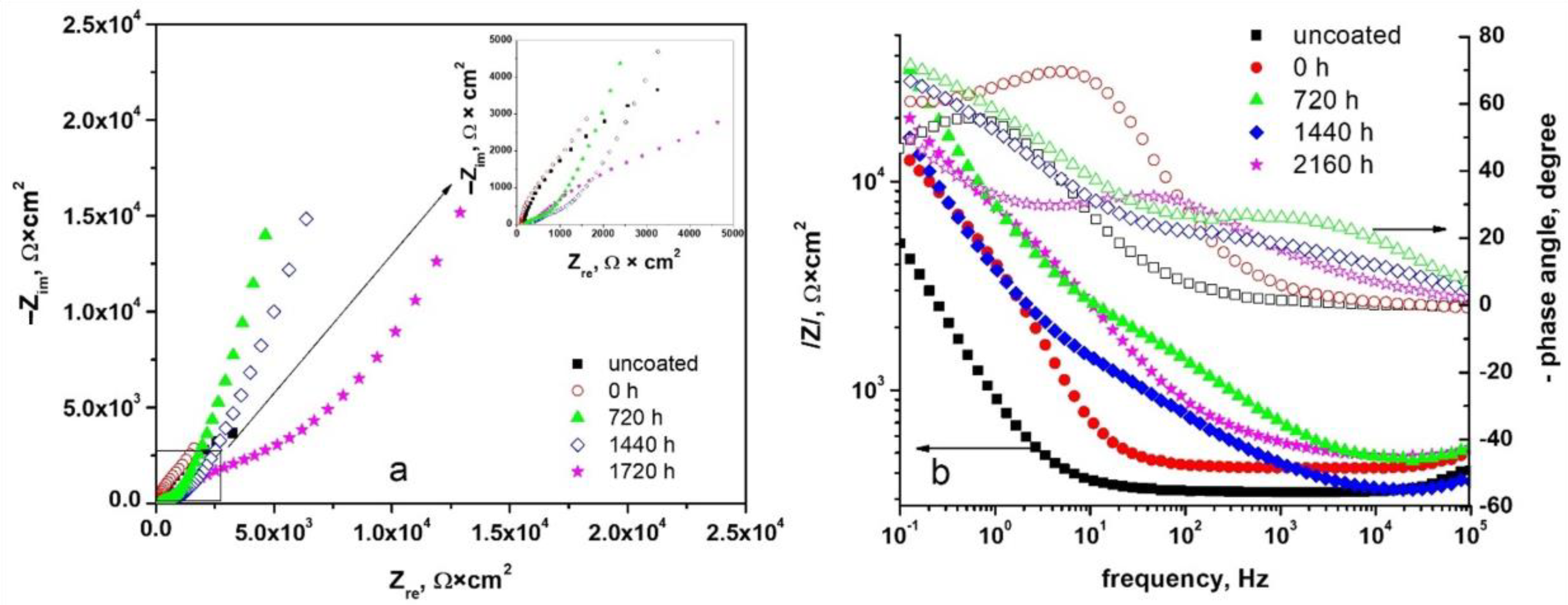
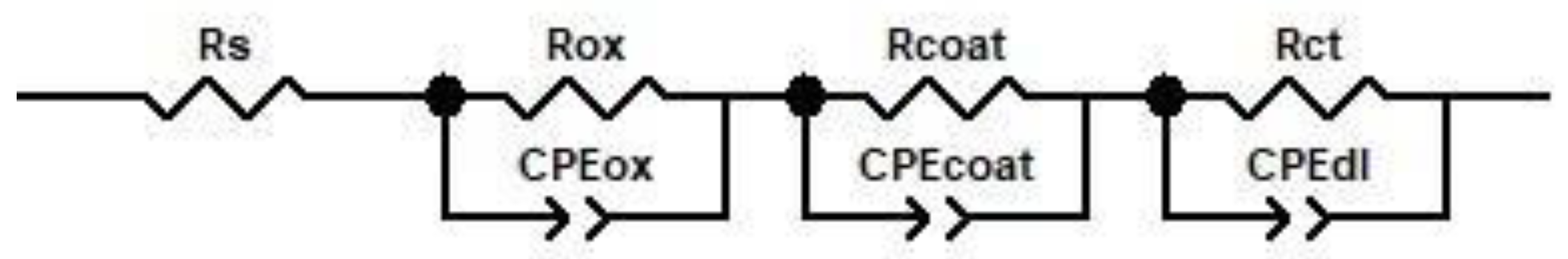
3.3.1. Electrochemical Impedance Spectroscopy (EIS)

To evaluate the protective nature of the NiCrAlY layers deposited by the EB-PVD method, the electrochemical impedance spectroscopy (EIS) method was applied, which is a method that does not accelerate reactions at a metal/solution interface [46,47,48,49].
Figure 8a,b shows the Nyquist (a) and Bode diagrams (b) obtained for the 310H stainless steel samples coated with a layer of NiCrAlY and oxidized for different periods of time in water at 550 °C and 25 MPa. A qualitative characterization of the oxides formed on the sample surfaces after oxidation in an aqueous medium at high temperatures can be made using these diagrams.
Following the Nyquist diagrams shown in Figure 8a, it can be observed that for both the uncoated sample and the sample coated with NiCrAlY, a single capacitive semicircle was obtained. In the case of NiCrAlY-coated samples oxidized for different periods of time, two capacitive semicircles were obtained. These can be associated with two created interfaces. The semicircle recorded at medium and low frequencies corresponds to the NiCrAlY-deposited layer and the semicircle recorded at high frequencies correspond to the oxide layer formed on the sample surface following the oxidation tests.
Furthermore, these diagrams show an increase in diameter semicircles with the oxidation time increase. This determines a higher polarization resistance value; thus, there is a smaller corrosion rate for coated samples that were oxidized for 2160 h, indicating a better corrosion resistance of these samples compared to the other samples.
The Bode diagrams (Figure 8b) make the existence of two maximum values of phase angles evident for each analyzed sample, one at medium and low frequencies and another at high frequencies, corresponding to the two semicircles on the Nyquist diagram (Figure 8a).
Corrosion processes at the substrate–coating interface are represented by impedances recorded at medium and low frequencies, while corrosion processes at the oxide–solution interface are represented by impedances measured at high frequencies [50,51,52,53,54].
To obtain the quantitative data, all experimental EIS data were fitted with the ZView 2.90 software. The equivalent electrical circuit (EEC) is represented in Figure 9. The equivalent electrical circuit model is similar to the one used by our group for the study of the uncoated substrate [39], or those that were coated with CrxN and oxidized under similar conditions [22]. The values of the elements of the equivalent circuits determined for all tested samples are presented in Table 5.
Table 5 shows that in the case of all tested samples, for the capacity of the oxide layer, the capacity of the deposited layer, a capacitive element, could not be used; thus, a distributive element consisting of the constant phase element CPE-T and the CPE-P parameter was used instead.
The coating resistance (Rcoat) shows a progressive increase with the following oxidation times: 11,455 Ω × cm2 at 720 h, 2.54 × 10⁶ Ω × cm2 at 1440 h, and 3.1 × 10⁶ Ω × cm2 at 2160 h. This trend indicates a strengthening of the oxide layer’s protective properties as the exposure time increases. The substantial increase in Rcoat between 720 and 1440 h, followed by a more moderate increase at 2160 h, suggests a gradual densification and stabilization of the oxide layer on the NiCrAlY coating. This sequential increase in resistance, mirrored by the rising Rox values over time, reflects the coating’s enhanced ability to impede corrosion with prolonged exposure. Additionally, the high CPEox-p values, which approach 1, reflect a strong capacitive behavior that is indicative of a more uniform and protective oxide layer after extended oxidation. Table 5 shows that, in the case of all tested samples, a value of Chi-square (χ2) ≈ 10−3 was found, and the fitting errors were quite small.
An approach based on the Kramers–Kronig transforms was used to determine the polarization resistance values (Rp). The imaginary impedance component summed over the measured frequency domain is used in this method to estimate the polarization resistance [55].
Table 6 presents Rp and i0 values obtained for uncoated and coated samples with NiCrAlY, unoxidized and oxidized for 720 h, 1440 h, and 2160 h in water at 550 °C and 25 MPa.
Comparing the Rp values estimated from the Nyquist diagrams (Figure 8a) and using a method derived from the Kramers–Kronig transforms (Table 6), it is observed that for the samples coated and oxidized in a supercritical environment for a longer period of time (2160 h), the highest polarization resistance value (0.514 MΩ × cm2) and the lowest corrosion current density value (24.6 nA × cm−2) were obtained. According to the Buttler–Volmer equation (Equation (7)), polarization resistance is inversely proportional to the corrosion current density; therefore, a higher polarization resistance value indicates a lower corrosion rate value. The conclusion, which is congruent with the findings of the gravimetric study, would be that samples of oxidized steel that had been exposed to a supercritical environment over a longer period of time had lower corrosion rates than samples that were unoxidized or oxidized for a shorter period of time.
R T = Δ η Δ i = R T z F 1 i 0
where:
i0: corrosion current density [A × cm−2];
R: gas constant [8.314 J × mol−1 × K−1];
F: Faraday’s constant [9.65 × 10⁴ C × mol−1];
T: absolute temperature, [K];
z: the valence of the ion;
R: polarization resistance, [Ω].

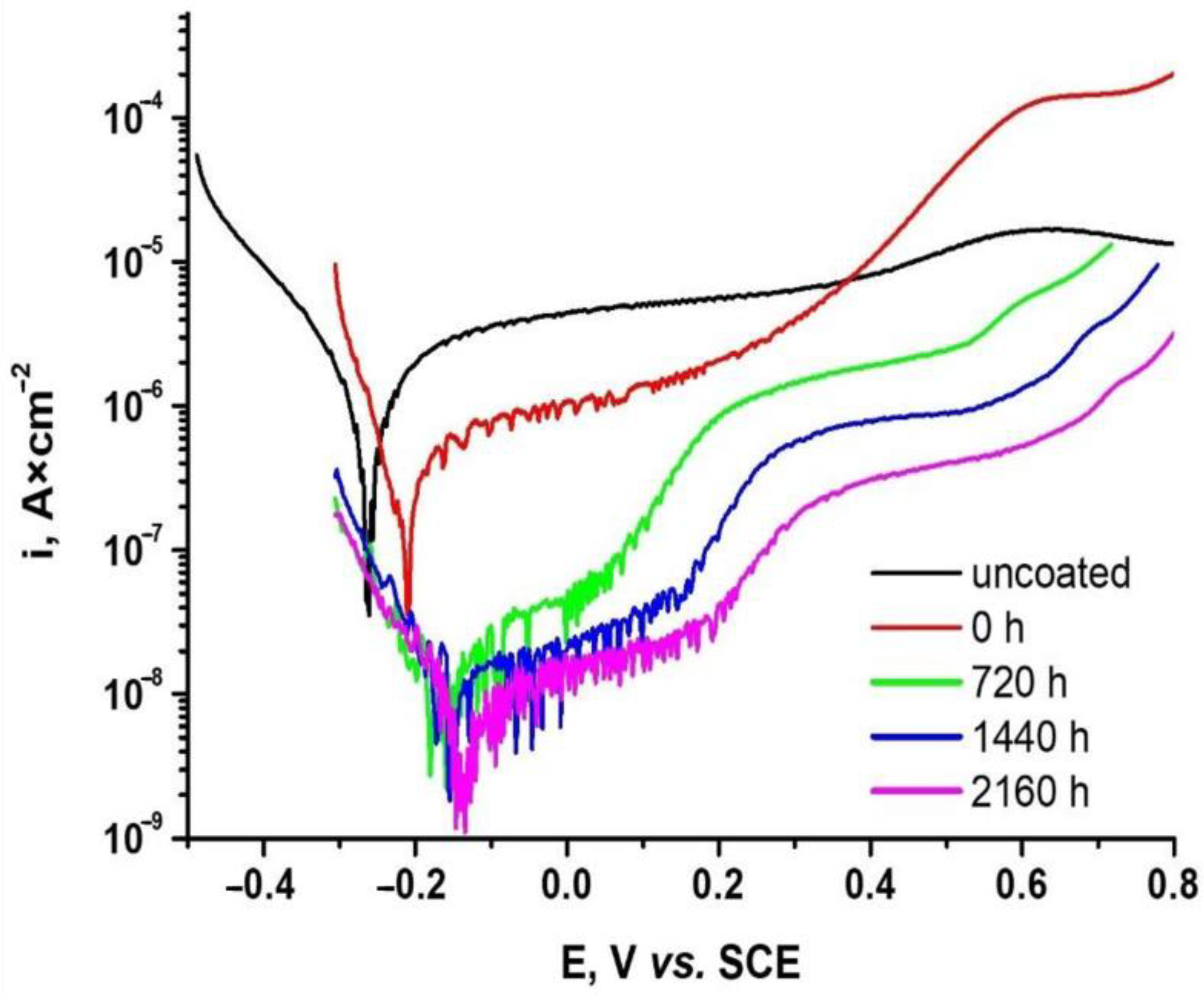
3.3.2. Potentiodynamic Linear Polarization

To study the corrosion behavior of the 310H stainless steel samples coated with a layer of NiCrAlY using the EB-PVD method after exposure for different periods in the specific environment of an SCW reactor, the potentiodynamic polarization plots were recorded starting from a potential of −0.250 V vs. OCP up to +1.0 V. A scan rate of 0.5 mV/s was used. The obtained potentiodynamic polarization plots are shown in Figure 10.
Following the shape of the polarization plots shown in Figure 10, it can be seen that in the case of the samples coated with a layer of NiCrAlY and oxidized for 2160 h, more electropositive values of the corrosion potential and lower corrosion current density values were recorded, which indicate a better corrosion resistance of these samples compared to unoxidized ones or those oxidized under the same conditions for a shorter period of time. These observations indicate that the oxide films are more protective and provide better corrosion resistance, which is also evidenced by the EIS analysis.
The electrochemical parameters determined from potentiodynamic polarization plots using the Tafel slopes extrapolation and polarization resistance (Rp) methods, as well as the protection efficiency (Pi) and porosity (P) values, are presented in Table 7.
As this table shows, similar values of the electrochemical parameters were obtained by the Tafel and Rp methods. Thus, it is observed that the sample coated with a layer of NiCrAlY and oxidized for 2160 h has the best corrosion protection, which is indicated by the lowest corrosion current density value (4.62 nA × cm−2) and the corrosion rate (4.8 × 10⁻⁵ mm × year−1), which possess a greater electropositive corrosion potential (−123 mV) and the highest polarization resistance value (7.3 × 10³ KΩ × cm2). These values are consistent with the observations made on the polarization plots. The improvement of the corrosion rate by almost two orders of magnitude can be explained by the appearance in the first stage of a mixture of chromium oxide and aluminum oxide with an underlying Al2O3 (in the fast stage of the mechanism of the oxidation process) [40,42,43]. The slower decrease in the corrosion rate for the samples oxidized for 1440 h or 2160 h, compared to samples oxidized for 720 h, can be explained by the predominantly slow growth of the Al2O3 layer, according to the second stage of the proposed oxidation mechanism.
Furthermore, in the case of this sample, the highest protective efficiency value (99.55%) and the lowest porosity value (1.67 × 10⁻⁴%) indicate the formation of more protective films on the surface of these samples.
To better illustrate the dependence of the corrosion speed calculated from the potentiodynamic polarization curves on the coating thickness, the graph in Figure 11 was made. It can be noted that a rapid decrease in the value of the corrosion speed for the samples coated with a layer of NiCrAlY and oxidized under conditions of high temperature and pressure are comparable to the non-oxidized sample. At the same time, it can be observed that, for the samples tested under supercritical conditions, the increase in the thickness of the coating leads to a decrease in the value of the corrosion speed, indicating good corrosion behavior of the oxidized samples.
Porosity, a measure of the density of the oxide defect, and its corrosion behavior, could be related. Several studies in the literature [56,57,58] have found that samples with lower porosity, lower corrosion current densities and rates, higher polarization potentials, and higher polarization resistivities exhibit the best oxide protective efficiencies (and can prevent corrosion the best). These findings are supported by the results.

4. Conclusions

In the present study, the morphological, structural, and electrochemical characterization of samples coated with a layer of NiCrAlY deposited using the EB-PVD method, before and after exposure in water at 550 °C and 25MPa for up to 2160 h, was investigated.
All of the studied samples gained weight according to the gravimetric analysis, and the oxidation of the 310H alloy covered with NiCrAlY in water at 550 °C follows a logarithmic law; with an oxidation time increase, the oxide thicknesses increased, and the corrosion rates decreased. The lowest value of the corrosion rate of 0.27 μm × year−1, obtained for the coated sample and oxidized for the longest period, has better corrosion resistance.
The GIXRD analyses revealed the presence of NiCrAlY as the deposition layer in the coated and unoxidized samples. In the coated and oxidized samples, chromium oxide (Cr2O3) and the Corundum phase (Al2O3) were identified. Additionally, an increase in the intensity of peaks characteristic of Cr2O3 and Al2O3 was observed with longer oxidation times.
SEM analysis highlighted the deposition of an initial layer of NiCrAlY on the surface of stainless steel, which exhibited discontinuities, and whose thickness measured by SEM in a cross-section was 1.48 μm. The coating layer is granular, without visible defects (pores, cracks). After oxidation, a thin, compact, and uniform oxide layer was formed on sample surfaces. A mechanism for the growth of the oxide layer consisting of two stages was proposed, as follows: one fast and the other slower, after which a mixed oxide layer on the surface and an underlying Al2O3 is formed.
The EIS analysis with Bode and Nyquist diagrams and equivalent circuits showed that the 310H steel samples coated with NiCrAlY using the EB-PVD method and oxidized for the longest period of time have a better corrosion resistance, which is a conclusion evidenced by the potentiodynamic method as well. The highest protective efficiency value (99.55%) and the lowest porosity value (1.67 × 10⁻⁴%) observed over a longer time in the case of oxidized samples suggested the development of greater protective coatings on their surface.
This is further supported by the lower values of corrosion current densities, corrosion rates, higher corrosion potentials, and higher polarization resistances reported in oxidized samples for a longer period of time.
Based on the obtained and detailed results, including the electrochemical aspects, a more complete behavior in the aggressive media of an EB-PVD coating on 310H alloys was discussed, and a good correlation between gravimetric analysis, scanning electron microscopy, and the electrochemical method was found.

Author Contributions

Conceptualization, F.G., A.-E.T. and I.D.; methodology, F.G., A.-E.T. and L.F.M.; software, A.-E.T. and L.F.M.; validation, F.G. and I.D.; formal analysis, A.-E.T. and L.F.M.; investigation, F.G. and A.-E.T.; resources, F.G.; data curation, F.G., A.-E.T. and I.D.; writing—original draft preparation, F.G., A.-E.T. and I.D.; writing—review and editing, F.G. and I.D.; visualization, F.G. and I.D.; supervision, I.D.; project administration, F.G.; funding acquisition, F.G. All authors have read and agreed to the published version of the manuscript.

Funding

This research was funded by a grant from the National Program for Research of the National Association of Technical Universities, GNAC ARUT 2023.

Institutional Review Board Statement

Not applicable.

Informed Consent Statement

Not applicable.

Data Availability Statement

The raw data supporting the conclusions of this article will be made available by the authors upon request.

Acknowledgments

The authors would like to thank the National Association of Technical Universities for providing the resources that supported this work.

Conflicts of Interest

The authors declare no conflicts of interest.

References

  1. United Nations Economic Commission for Europe. Carbon Neutrality in the UNECE Region: Integrated Life-Cycle Assessment of Electricity Sources; United Nations: Geneva, Switzerland, 2022. [Google Scholar]
  2. Stanculescu, A. Worldwide status of advanced reactors (GEN IV) research and technology development. In Encyclopedia of Nuclear Energy; Greenspan, E., Ed.; Elsevier: Amsterdam, The Netherlands, 2021; pp. 478–489. ISBN 9780128197325. [Google Scholar]
  3. Yvon, P. Structural Materials for Generation IV Nuclear Reactors, 1st ed.; Yvon, P., Ed.; Woodhead Publishing: Sawston, UK, 2016; ISBN 9780081009062. [Google Scholar]
  4. Griffiths, M. Effect of Neutron Irradiation on the Mechanical Properties, Swelling and Creep of Austenitic Stainless Steels. Materials 2021, 14, 2622. [Google Scholar] [CrossRef] [PubMed]
  5. Maziasz, P.J.; Busby, J.T. Properties of Austenitic Steels for Nuclear Reactor Applications. In Comprehensive Nuclear Materials; Elsevier: Amsterdam, The Netherlands, 2012; pp. 267–283. [Google Scholar]
  6. Reinhold, E.; Faber, J. Large area electron beam physical vapor deposition (EB-PVD) and plasma activated electron beam (EB) evaporation. Status and prospects. Surf Coat. Tech. 2011, 206, 1653–1659. [Google Scholar] [CrossRef]
  7. Mikulla, C.; Steinberg, L.; Niemeyer, P.; Schulz, U.; Naraparaju, R. Microstructure Refinement of EB-PVD Gadolinium Zirconate Thermal Barrier Coatings to Improve Their CMAS Resistance. Coatings 2023, 13, 905. [Google Scholar] [CrossRef]
  8. Feuerstein, A.; Knapp, J.; Taylor, T.; Ashary, A.; Bolcavage, A.; Hitchman, N. Technical and economical aspects of current thermal barrier coating systems for gas turbine engines by thermal spray and EBPVD: A Review. J. Therm. Spray Technol. 2008, 17, 199–213. [Google Scholar] [CrossRef]
  9. Zhen, Z.; Qu, C.; Fu, D. Characterization of the Internal Stress Evolution of an EB-PVD Thermal Barrier Coating during a Long-Term Thermal Cycling. Materials 2023, 16, 2910. [Google Scholar] [CrossRef]
  10. Lee, G.-W.; Lee, I.-H.; Oh, Y.-S. Oxidation-Induced Changes in the Lattice Structure of YSZ Deposited by EB-PVD in High-Vacuum Conditions. Processes 2023, 11, 2743. [Google Scholar] [CrossRef]
  11. Ziyuan, X.; Yingying, Y.; Shijie, M.; Weidong, W.; Qiguo, Y. Review on corrosion of alloys for application in supercritical carbon dioxide brayton cycle. Heliyon 2023, 9, e22169. [Google Scholar] [CrossRef]
  12. Van Nieuwenhove, R.; Balak, J.; Ejenstam, J.; Szakalos, P. Investigations of CrN and AlCrN coatings, applied by PVD, for the corrosion protection of metals in liquid lead at 550 °C. In Proceedings of the The Nuclear Materials Conference (NuMat), Clearwater, FL, USA, 27–30 October 2014. [Google Scholar]
  13. Gui, Y.; Liang, Z.; Zhao, Q. Corrosion and carburization behavior of heat-resistant steels in a high-temperature supercritical carbon dioxide environment. Oxid. Met. 2019, 92, 123–136. [Google Scholar] [CrossRef]
  14. Yae Kina, A.; Tavares, S.S.M.; Pardal, J.M.; Souza, J.A. Microstructure and intergranular corrosion resistance evaluation of AISI 304 steel for high temperature service. Mater. Charact. 2008, 59, 651–655. [Google Scholar] [CrossRef]
  15. Yang, L.; Qian, H.; Kuang, W. Corrosion Behaviors of Heat-Resisting Alloys in High Temperature Carbon Dioxide. Materials 2022, 15, 1331. [Google Scholar] [CrossRef] [PubMed]
  16. Tavares, S.S.M.; Moura, V.; da Costa, V.C.; Ferreira, M.L.R.; Pardal, J.M. Microstructural Changes and Corrosion Resistance of AISI 310S Steel Exposed to 600–800 °C. Mater. Charact. 2009, 60, 573–578. [Google Scholar] [CrossRef]
  17. Singh, M.; Gupta, V.K.; Bansal, A.; Sharma, Y. High temperature oxidation behaviour of NiCrAlY clad developed on SS-304 through microwave irradiation. Results Surf. Interfaces 2024, 14, 100179. [Google Scholar] [CrossRef]
  18. Schulz, U.; Leyens, C.; Fritscher, K.; Peters, M.; Saruhan-Brings, B.; Lavigne, O.; Dorvaux, J.M.; Poulain, M.; Mevrel, R.; Caliez, M. Some recent trends in research and technology of advanced thermal barrier coatings. Aero. Sci. Technol. 2003, 7, 73–80. [Google Scholar] [CrossRef]
  19. Hebbale, A.J.; Ramesh, M.R.; Petru, J.; Chandramouli, T.V.; Srinath, M.S.; Shetty, R.K. A microstructural study and high-temperature oxidation behaviour of plasma sprayed NiCrAlY based composite coatings. Results Eng. 2025, 25, 103926. [Google Scholar] [CrossRef]
  20. IAEA-TECDOC-1869; Status of Research and Technology Development for Supercritical Water Cooled Reactors. International Atomic Energy Agency: Vienna, Austria, 2019.
  21. Pennefather, R.C.; Boone, D.H. Mechanical degradation of coating systems in high-temperature cyclic oxidation. Surf. Coat. Technol. 1995, 76–77, 47–52. [Google Scholar] [CrossRef]
  22. Tudose, A.; Golgovici, F.; Anghel, A.; Fulger, M.; Demetrescu, I. Corrosion Testing of CrNx-Coated 310 H Stainless Steel under Simulated Supercritical Water Conditions. Materials 2022, 15, 5489. [Google Scholar] [CrossRef] [PubMed]
  23. Petrescu, D.; Nițu, A.; Golgovici, F.; Demetrescu, I.; Corban, M. Behaviour Aspects of an EB-PVD Alumina (Al2O3) Film with an Interlayer (NiCrAlY) Deposited on AISI 316L Steel Investigated in Liquid Lead. Metals 2023, 13, 616. [Google Scholar] [CrossRef]
  24. Wang, X.; Yan, H.; Li, N.; Jiang, Z. High-temperature oxidation behavior of 301 stainless steel containing Cu. Mater. Today Commun. 2021, 35, 106121. [Google Scholar] [CrossRef]
  25. Huang, X.; Xiao, K.; Fang, X.; Xiong, Z.; Wei, L.; Zhu, P.; Li, X. Oxidation behavior of 316L austenitic stainless steel in high temperature air with long-term exposure. Mater. Res. Express 2020, 7, 066517. [Google Scholar] [CrossRef]
  26. Gurtaran, M.; Zhang, Z.; Li, X.; Dong, H. High-Temperature Oxidation Behaviour of CrSi Coatings on 316 Austenitic Stainless Steel. Materials 2023, 16, 3533. [Google Scholar] [CrossRef]
  27. Tudose, A.E.; Golgovici, F.; Demetrescu, I.; Fulger, M.; Anghel, A.; Brincoveanu, O. Influence of chromium nitride ceramic layers thicknesses developed onto 310 H stainless steel on the corrosion resistance. U.P.B. Sci. Bull. Ser. B 2022, 84, 191–202. [Google Scholar]
  28. Gong, X.; Chen, R.R.; Wang, Y.; Su, Y.Q.; Guo, J.J.; Fu, H.Z. Microstructure and Oxidation Behavior of NiCoCrAlY Coating with Different Sm2O3 Concentration on TiAl Alloy. Front. Mater. Sec. Polym. Compos. Mater. 2021, 8, 710431. [Google Scholar] [CrossRef]
  29. Outokumpu Stainless AB Company. Inspection Certificate No. 1293516/ 18.05.2007-1.4484; Outokumpu Stainless AB Company: Dalarna, Sweden, 2007. [Google Scholar]
  30. Huang, X.; Yang, Q.; Guzonas, D. Performance of Chemical Vapor Deposition and Plasma Spray-Coated Stainless Steel 310 in Supercritical Water. J. Nuclear Rad. Sci. 2016, 2, 1011-1–1011-8. [Google Scholar] [CrossRef]
  31. Hӧganӓs, Sweden. Inspection Certificate 3.1 per EN10204/ 07.11.2018; Hӧganӓs: Hoganas, Sweden, 2018. [Google Scholar]
  32. Piticescu, R.; Urbina, M.; Rinaldi, A. Development of novel material systems and coatings for extreme environments: A Brief Overview. JOM 2019, 71, 683–690. [Google Scholar] [CrossRef]
  33. Urbina, M.; Rinaldi, A.; Cuesta-Lopez, S.; Sobetkii, A.; Slobozeanu, A.E.; Szakalos, P.; Qin, Y.; Prakasam, M.; Piticescu, R.-R.; Ducros, C.; et al. The methodologies and strategies for the development of novel material systems and coatings for applications in extreme environments—A critical review. Manuf. Rev. 2018, 5, 9. [Google Scholar] [CrossRef]
  34. Baboian, R. Corrosion Tests and Standards: Application and Interpretation; ASTM Manual Series: MNL 20; ASTM Publication Code Number (PCN): 28-020095-27; ASTM: West Conshohocken, PA, USA, 1995; Volume 1. [Google Scholar]
  35. Gălan, F.; Ducu, M.; Fulger, M.; Negrea, D. Investigation of oxidation behavior of 304l and 310s steels with potential application in supercritical water-cooled nuclear reactors. Rev. Chim. 2020, 71, 98–105. [Google Scholar] [CrossRef]
  36. Yang, J.; Li, Y.; Macdonald, D.D. Effects of temperature and pH on the electrochemical behaviour of alloy 600 in simulated pressurized water reactor primary water. J. Nucl. Mater. 2020, 528, 151850. [Google Scholar] [CrossRef]
  37. Olasunkanmi, J.A. Surface Defects Characterization and Electrochemical Corrosion Studies of TiAlN, TiCN and AlCrN PVD Coatings. Master’s Thesis, Materials and Processes of Sustainable Energetics KAYM09, Tallinn, Estonia, 2016. [Google Scholar]
  38. Tsegay, M.G.; Gebretinsae, H.G.; Nuru, Z.Y. Structural and optical properties of green synthesized Cr2O3 nanoparticle. Mater. Today Proc. 2021, 36, 587–590. [Google Scholar] [CrossRef]
  39. Tudose, A.; Demetrescu, I.; Golgovici, F.; Fulger, M. Oxidation behavior of an austenitic steel (Fe, Cr and Ni), the 310 H, in a deaerated supercritical water static system. Metals 2021, 11, 571. [Google Scholar] [CrossRef]
  40. Peng, B.; Xu, Y.X.; Fan, Z.; Wang, Q. Oxidation behavior at 1100 ◦C of NiCrAlY coatings deposited by various PVD technique. Surf. Coat. Technol. 2024, 477, 130307. [Google Scholar] [CrossRef]
  41. Peng, B.; Xu, Y.X.; Qimin Wang, Q. High-temperature structural evolution and mechanical properties of oxygen-containing NiCrAlY coatings. Appl. Surf. Sci. 2024, 671, 160745. [Google Scholar] [CrossRef]
  42. Dai, S.; Li, X.; Yang, S.; Lyu, P.; Ye, Y.; Hua, Y.; Cai, J. Comparison of oxidation behavior of NiCrAlY coatings before and after surface aluminizing modification. Mater. Today Commun. 2024, 38, 108326. [Google Scholar] [CrossRef]
  43. Huang, L.; Zhou, Z.; Yang, L.; Qiao, Y. The Oxidation Properties of a NiCrAlY Coating Fabricated by Arc Ion Plating. Coatings 2023, 13, 22. [Google Scholar] [CrossRef]
  44. Xie, Y.; Liu, J.; Luo, J.; Li, Q.; Zhang, J.; Yang, L.; Zhou, Y. Investigation on the Oxidation Behavior of the NiCrAlY Bond-Coat with Low Al Content Sprayed by High Velocity Oxygen Fuel Method. J. Therm. Spray. Tech. 2024, 33, 1510–1525. [Google Scholar] [CrossRef]
  45. Zhu, Y.; Guo, T.; Geng, P.; Yu, H.; Wu, Y.; Gao, K.; Pang, X. Research on oxidation kinetics of CoNiCrAlY coatings in pure steam environment. Corros. Sci. 2024, 224, 111532. [Google Scholar] [CrossRef]
  46. Bojinov, M.; Fabricius, G.; Kinnunen, P.; Sundholm, G. EIS and CER study of the passivity of NiCr Alloys in a neutral solution at 200 °C. In Proceedings of the The International Symposium on Electrochemistry Methods in Corrosion Research, Budapest, Hungary, 28 May–1 June 2000. [Google Scholar]
  47. Baek, J.S.; Kim, J.G.; Hur, D.H. Anodic film properties determined by EIS and their relationship with caustic SCC of Alloy 600. Corros. Sci. 2003, 45, 983–994. [Google Scholar] [CrossRef]
  48. Marcus, P.; Mansfeld, F. Analytical Methods in Corrosion Science and Engineering; CRC Press: New York, NY, USA, 2006; ISBN 13: 978-0-8247-5952-0. [Google Scholar]
  49. Cicek, V. Corrosion Engineering, in In Martin Scrivener; Phillip Carmical: Beverly, MA, USA, 2014. [Google Scholar]
  50. Mutyala, K.C.E.; Ghanbari, E.; Doll, G.L. Effect of deposition method on tribological performance and corrosion resistance characteristics of CrxN coatings deposited by physical vapor deposition. Thin Solid Films 2017, 636, 232–239. [Google Scholar] [CrossRef]
  51. Härkönen, E.; Díaz, B.; Światowska, J.; Maurice, V.; Seyeux, A.; Vehkamäki, M.; Sajavaara, T.; Fenker, M.; Marcus, P.; Ritala, M. Corrosion protection of steel with oxide nanolaminates grown by atomic layer deposition. J. Electrochem. Soc. 2011, 158, C369. [Google Scholar] [CrossRef]
  52. Wang, Z.; Li, J.; Wang, Y.; Wang, Z. An EIS analysis on corrosion resistance of anti-abrasion coating. Surf. Interfaces 2017, 6, 33–39. [Google Scholar] [CrossRef]
  53. Fusco, M.; Ay, Y.; Casey, A.; Bourham, M.; Leigh, A. Winfrey, Corrosion of single layer thin film protective coatings on steel substrates for high level waste containers. Prog. Nuclear Energy 2016, 89, 159–169. [Google Scholar] [CrossRef]
  54. El-Azazy, M.; Min, M.; Annus, P. Electrochemical Impedance Spectroscopy; WILEY: Hoboken, NJ, USA, 2020. [Google Scholar]
  55. Feng, Z.; Hurley, B.; Buchheit, R. Corrosion Inhibition Study of Aqueous Vanadate on Mg Alloy AZ31. J. Electrochem. Soc. 2018, 165, C94–C102. [Google Scholar] [CrossRef]
  56. William Grips, V.K.; Barshilia, H.C.; Selvi, V.E.; Rajam, K.S. Electrochemical behavior of single layer CrN, TiN, TiAlN coatings and nanolayered TiAlN/CrN multilayer coatings prepared by reactive direct current magnetron sputtering. Thin Solid Films 2006, 514, 204–211. [Google Scholar] [CrossRef]
  57. Zhang, L.; Chen, Y.; Feng, Y.P.; Chen, S.; Wan, Q.L.; Zhu, J.F. Electrochemical characterization of AlTiN, AlCrN and AlCrSiWN coatings. Int. J. Refract. Met. Hard Mater. 2015, 53, 68–73. [Google Scholar] [CrossRef]
  58. Yoo, Y.H.; Le, D.P.; Kim, J.G.; Kim, S.K.; Van Vinh, P. Corrosion behavior of TiN, TiAlN, TiAlSiN thin films deposited on tool steel in the 3.5 wt.% NaCl solution. Thin Solid Films 2008, 516, 3544–3548. [Google Scholar] [CrossRef]
Figure 1. (a) EB-PVD-type Torr45KW installation; (b) schematic representation of the evaporation process.
Applsci 15 02361 g001
Figure 2. Oxidation kinetics of NiCrAlY-coated 310H steel samples at high temperature.
Applsci 15 02361 g002
Figure 3. Oxide thickness and oxidation rate dependence on exposure time in water at 550 °C and 25 Mpa of NiCrAlY-coated 310H stainless steel.
Applsci 15 02361 g003
Figure 4. X-ray diffraction spectra for 310H stainless steel samples coated with NiCrAlY and exposed for different periods in water at 550 °C and 25 Mpa.
Applsci 15 02361 g004
Figure 5. SEM micrographs at magnifications of 10 kx and 50 kx obtained for coated samples before and after oxidation in water at high temperatures for (a) 0 h; (b) 720 h; (c) 1440 h; and (d) 2160 h.
Applsci 15 02361 g005
Figure 6. Layer thicknesses at magnifications of 10 kx and 50 kx were obtained for coated samples before and after oxidation in water at high temperatures for (a) 0 h; (b) 720 h; (c) 1440 h; and (d) 2160 h.
Applsci 15 02361 g006
Figure 7. Schematic diagram of the oxidation process of NiCrAlY coatings.
Applsci 15 02361 g007
Figure 8. Nyquist diagrams (a) and Bode diagrams (b) were obtained for uncoated and NiCrAlY-coated 310H stainless steel samples before and after oxidation for different periods in water at 550 °C and 25 MPa.
Applsci 15 02361 g008
Figure 9. The proposed model for the equivalent circuit was determined after fitting the results for 310H samples coated with a layer of NiCrAlY and oxidized for different periods.
Applsci 15 02361 g009
Figure 10. Potentiodynamic plots for NiCrAlY-coated 310H steel samples before and after oxidation for 720 h, 1440 h, and 2160 h in water at 550 °C and 25 MPa.
Applsci 15 02361 g010
Figure 11. Dependence of the corrosion rate on the coating thickness.
Applsci 15 02361 g011
Table 1. The chemical composition of 310 H SS.
Alloying Elements, [wt. %]
CSiMnPSCrNiNFe
0.0630.711.610.0160.00124.1319.030.0454.34
Table 2. Coating chemical composition.
Powder TypeParticle Size,
μm
Element, wt. %
NiCrAlY
Amperit@413.006 NiCrAlY atomized gas125/45672210 0.9
Table 3. Deposition parameters (EB-PVD method).
ParameterValue
Starting vacuum5.3 × 10−3 Pa
Working vacuum2.7 × 10−3 Pa
Deposit speed2 A/s
E-Beam beam power1–2 KW
Distance between the crucible and the substrate1.2 m
Substrate heaterset to the maximum value of 800 °C
Total deposition time4 h
Table 4. Kinetic parameters determined for NiCrAlY-coated 310H stainless steel samples after oxidation in water at supercritical temperature.
Kinetics EquationknR2
y = 1.3029 × t0.21541.30290.21540.9991
Table 5. Equivalent circuit element values for unoxidized and oxidized coated samples for different periods in water at 550 °C and 25 MPa.
Element CircuitUncoated Sample Coated Sample
UnoxidizedOxidized Sample
720 h1440 h2160 h
Rs, Ω·cm2331.4325.6259.8300.3242.7
Rox, Ω·cm2--1.9 × 1045.8 × 1056.2 × 105
CPEox—T, F·cm−2--1.5 × 10−41.95 × 10−45.7 × 10⁻⁵
CPEox—P--0.680.530.54
Rcoat, Ω·cm2-8291114552.54 × 1063.1 × 106
CPEcoat—T, F·cm−2-2.53 × 10−43.4 × 10−48.6 × 10−56.4 × 10−5
CPEcoat—P-0.7860.970.950.97
Rct, Ω·cm28810160.9522.1529.6619
CPEdl—T, F·cm−22.61 × 10−45.91 × 10−72.4 × 10−53.6 × 10−53.7 × 10⁻⁵
CPEdl—P0.8560.520.680.650.79
Chi-squared (χ2)3.1 × 10−31.6 × 10−34.8 × 10−42.5 × 10−46.3 × 10⁻⁴
Table 6. Rp and i0 values obtained for unoxidized and oxidized NiCrAlY-coated 310H samples for different periods in water at 550 °C and 25 MP.
Sample TypePolarization Resistance (From the Extrapolation of Nyquist Diagrams),
(MΩ × cm2)
i0 (Calculated from Polarization Resistance).
(nA × cm−2)
310H_uncoated0.0342370
310H/NiCrAlY_0 h0.039320
310H/NiCrAlY_720 h0.29742.6
310H/NiCrAlY_1440 h0.38932.6
310H/NiCrAlY_2160 h0.51424.6
Table 7. Electrochemical parameter values calculated from Tafel slopes and Rp methods, Pi and P values determined for NiCrAlY-coated 310H stainless steel samples unoxidized and oxidized for different periods in water at 550 °C and 25MPa.
Sample TypeElectrochemical ParametersPi,
[%]
P,
[%]
Tafel Slopes MethodRp Method
Ecorr,
[mV]
icorr,
[nA × cm−2]
Vcorr,
[mm × year−1]
Rp,
[KΩ × cm2]
icorr,
[nA × cm−2]
uncoated−25610300.01126.071190--
0 h−2192000.00282.6122780.580.135
720 h−1648.438.9 × 10−52.5 × 1038.1499.181.25 × 10−3
1440 h−1617.177.5 × 10−53.6 × 1037.2599.308.01 × 10−4
2160 h−1234.624.8 × 10−57.3 × 1034.2999.551.67 × 10−4
Disclaimer/Publisher’s Note: The statements, opinions and data contained in all publications are solely those of the individual author(s) and contributor(s) and not of MDPI and/or the editor(s). MDPI and/or the editor(s) disclaim responsibility for any injury to people or property resulting from any ideas, methods, instructions or products referred to in the content.

