Article

Topology Optimization and Testing of Connecting Rod Based on Static and Dynamic Analyses

by
Mahalingam Nainaragaram Ramasamy
1,*,
Aleš Slíva
1,
Prasath Govindaraj
2 and
Akash Nag
2
1
Institute of Transport, Faculty of Mechanical Engineering, VSB-Technical University of Ostrava, 17. Listo-padu 15/2172, 70800 Ostrava, Czech Republic
2
Department of Mechanical Technology, Faculty of Mechanical Engineering, VŠB–Technical University of Ostrava, 70800 Ostrava, Czech Republic
*
Author to whom correspondence should be addressed.
Appl. Sci. 2025, 15(4), 2081; https://doi.org/10.3390/app15042081
Submission received: 26 January 2025 / Revised: 10 February 2025 / Accepted: 12 February 2025 / Published: 16 February 2025
(This article belongs to the Special Issue Computer-Aided Design in Mechanical Engineering)

Abstract

:
This research article outlines our aim to perform topology optimization (TO) by reducing the mass of the connecting rod of an internal combustion engine based on static structural and dynamic analyses. The basic components of an internal combustion engine like the connecting rods, pistons, crankshaft, and cylinder liners were designed using Autodesk Inventor Professional 2025. Using topology optimization, we aimed to achieve lesser maximum von Mises stress during static structural analysis and maintain a factor of safety (FOS) above 2.5 during rigid body dynamics. A force of 64,500 N was applied at the small end of the connecting rod while the big end was fixed. Topology optimization was carried out using ANSYS Discovery software at various percentages on a trial-and-error basis to determine better topology with lesser maximum von Mises stress. Target reduction was set to 4%, and as a result, 5.66% mass reduction from the original design and 6.25% reduced maximum von Mises stress was achieved. Later, transient analysis was carried out to evaluate the irregular motion loads and moments acting on the connecting rod at 1000 rpm. The results showed that the FOS remained above 2.5. Finally, the optimized connecting rod was simulated and verified for longevity using Goodman fatigue life analysis.

1. Introduction

The connecting rod is the most crucial and highly dynamic component of internal combustion engines, which helps in converting the reciprocating motion of the piston into the rotational motion of the crankshaft [1]. The connecting rod consists of a small end, shank, and big end, where the small end is connected to the piston using a piston pin, and the big end is attached to the crankshaft [2]. Irregular motion loads and moments due to crankshaft rotation combined with the combustion forces from the piston acting on the connecting rod play a vital role in optimizing this structure without affecting its longevity. Frictional energy loss plays an important role in mechanical efficiency and accounts for between 10% and 15% of the energy produced by internal combustion engines. Components of the engine and drivetrain, such as the piston rings, valve guides, cam followers, fuel injector pistons, shims, transmission gears, and front seals, are to varying degrees affected by friction. The selection of appropriate materials and lubricants and the proper design and size of an engine’s functional parts are not only necessary to minimize friction and wear on operational components but also to reduce friction and wear on engine components. The proper size of an engine can reduce fuel consumption by about 9% [3]. Finite element method (FEM) strength analysis is used to determine the cause of damage, evaluate structural integrity, and optimize design to prevent failure by simulating the distribution of stress and material behavior under different loading conditions [4]. In the past few years, computer-aided design (CAD) tools like SolidWorks 2024 and Autodesk Inventor 2025, and FEM tools like ABAQUS 2023HF2, NASTRAN 2023.4, etc., have evolved, and the TO process plays a major role in product improvement. The storage and reuse of the data from the CAD model for future improvement, adaptation, or use in different applications is widely implemented by many product developers [5].
CAD models are simulated with structural analysis to understand their deformation, displacement, etc. Structural analysis is a method used to study behavior under static loading conditions depending on material properties, mesh, and boundary conditions [6]. According to the Kisaru Shveli method, the FOS at the connecting rod body should be above 1.5, and at the big end and small end, it should be above 2.5 [7]. Dynamic analysis is a method used to evaluate the kinematics of assembly by studying motion while a system is kept rigid from deformation [8]. The application of the TO process has a large scope depending on the requirement of structural enhancements in fields like the automotive industry [9], robotics [10], aerospace [11], and industrial machinery [12]. There are several methods used to achieve TO, such as the density-based method, level-set method, evolutionary structural optimization, etc. [13]. The TO process is a computational method used to reduce the mass and the maximum von Mises stress of a defined boundary condition, while ensuring structural integrity, optimizing material distribution, and maintaining a suitable factor of safety for reliable performance under applied loads [13,14].
However, despite its application, limited research has addressed the TO of highly dynamic components like connecting rods, crankshafts, etc. The main objective of this research was to perform TO on a connecting rod using the finite element method and multibody dynamics by reducing the mass and maximum von Mises stress during static structural analysis. Unlike conventional topology optimization studies that focused exclusively on mass reduction, this research simultaneously optimized the distribution of stress and ensured structural integrity by maintaining a safety factor (FOS) above 2.5. The current study also incorporated static structural analysis, dynamic analysis, and fatigue life analysis (Goodman criteria) to fully evaluate the long-term durability of optimizing designs. In addition to the static TO, this study validated an optimal design under dynamic load and fatigue life analysis, ensuring that the connecting rod was stable under an irregular load and moment of motion.
Furthermore, material restrictions were introduced to ensure that optimized designs could be manufactured using traditional production methods such as forging and casting. These material savings can contribute to fuel efficiency and improved engine performance. An optimized design was evaluated by transitional analysis and fatigue under realistic load conditions to ensure that it remained structurally sound under operational stress. The results demonstrate that, when combined with rigorous structural validation, topology optimization can significantly improve the performance of components while reducing unnecessary material use.
This paper is structured in the following way: Section 1 (Introduction) explains the problem and objective of this research along with a description of the proposed solution; Section 2 (Materials and Methodology) describes the properties of the chosen material and the design of the IC engine components; Section 3 (Computational Analysis) describes the methodologies used; Section 4 (Results) includes a discussion and comparison of the results; Section 5 (Conclusion) explains the outcome of the research and future scope of this work; and the References section contains the bibliography of this work.

2. Materials and Methodology

2.1. Design and Material Selection

All the IC engine components including the connecting rod were designed using Autodesk Inventor Professional 2025. Since the objective of this study was to optimize the topology of the connecting rod, all other components were set as rigid bodies during the transient structural analysis and suppressed during the TO process.
The connecting rod was mostly designed with an I-Section for normal IC engines and an H-Section for race engines, and the mass of the connecting rod should be somewhere between 0.4 kg and 1 kg. The connecting rod ratio ( λ ) is defined by the relationship between the crank radius ( r c ) and the length of the connecting rod from the center of the small end and the big end ( l c r ). Typically for passenger car engines, the connecting rod ratio ( λ ) should be between 0.28 and 0.32 [15].
λ = r c l c r
λ = 45 153 = 0.2941
Here the connecting rod ratio ( λ ) was around 0.30 and it satisfied this condition [15]. The major dimensions of the original connecting rod geometry are shown in Figure 1.

2.1.1. Material Selection

The chosen connecting rod was made from 36MnVS4 and is used in the second generation of fracture-split material. This is the latest technology used while manufacturing connecting rods nowadays; in this method, the connecting rod is manufactured as a single component and then it is split into two halves at the crank end [16]. Based on the selected material, the mass of the initial connecting rod was 654 g. The major composition of this low-alloy steel is manganese and vanadium which improve its durability to withstand tensile, compressive, and buckling loads. Other materials like carbon, silicon, sulfur, phosphorus, and chromium can also be found in small quantities [17]. The properties of 36MnVS4 steel are shown in Table 1.

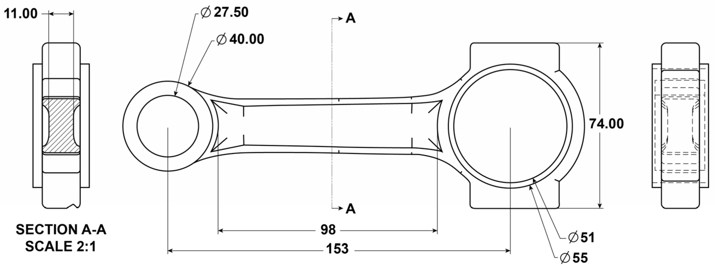
2.1.2. Design of Engine Components

Other components of the engine were designed to yield a low speed and high torque, based on the following assumed parameters: 4-cylinder inline engine, cylinder bore of 81 mm, and cylinder stroke length of 82.25 mm, which could run at a maximum speed of 1000 rpm in Table 2.

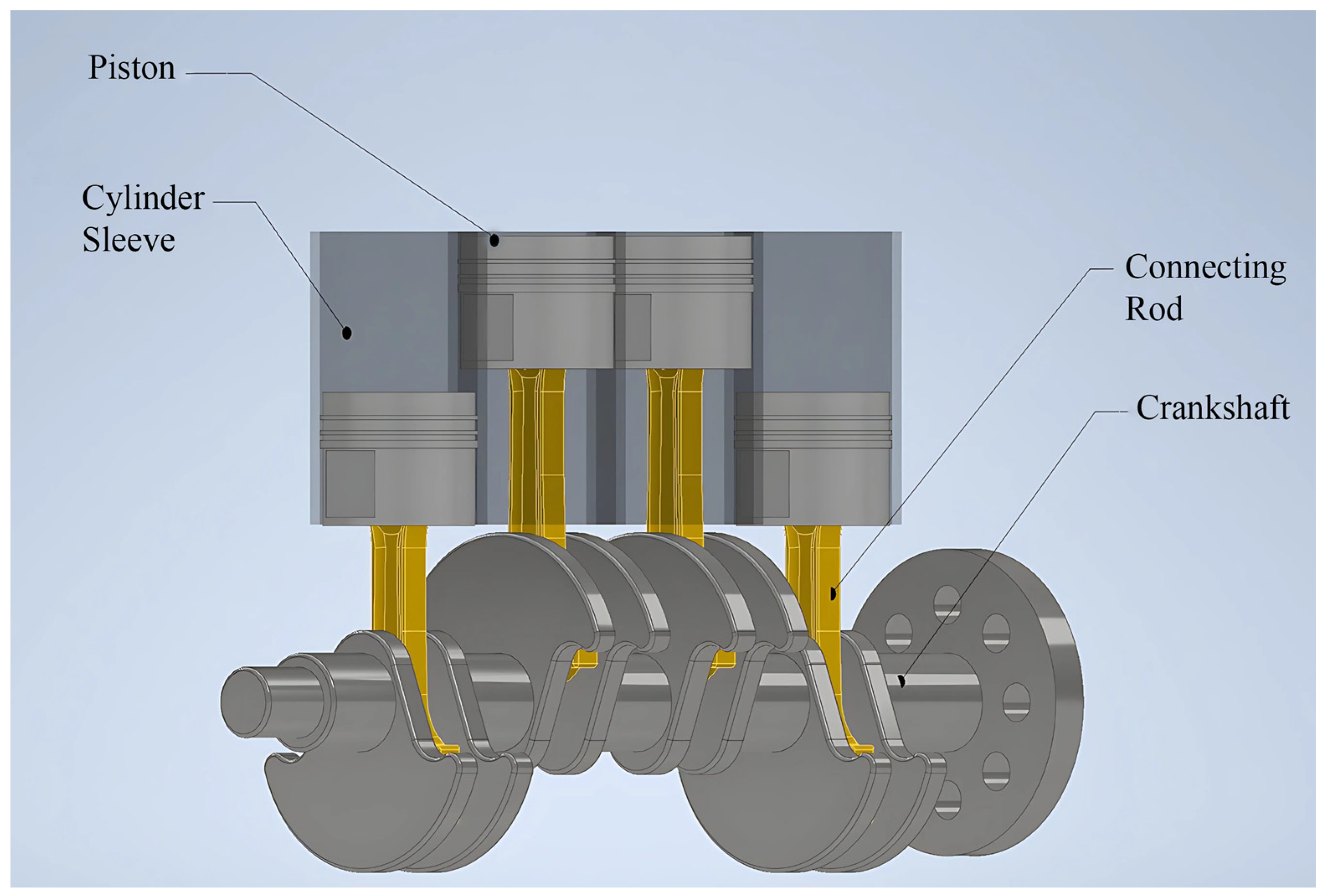
2.1.3. Assembly of Engine Components
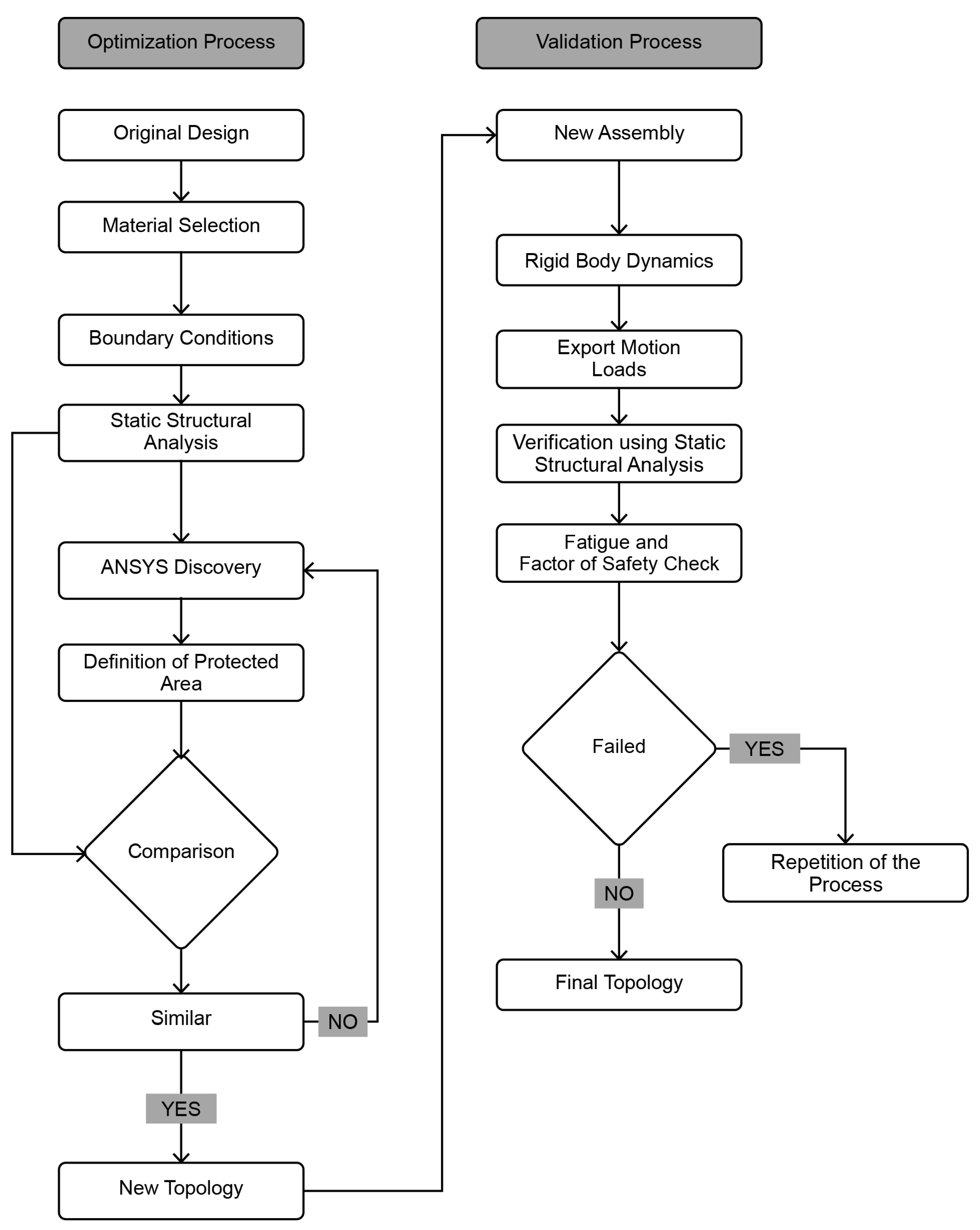
Since this assembly was designed only for motion study and kinematic analysis, the components in this IC engine assembly were minimized to four major components, the crankshaft, piston, connecting rod, and cylinder liner, avoiding small components like piston rings, bearings, etc. The precision of the other parts was not given priority, and the parts were designed to be close to fit and used only to evaluate the kinetics of unknown reaction forces and moments acting on the connecting rod. The assembly was made with the help of revolute joints, fixed joints, and translational joints. Figure 2 shows the assembly of the cylinder liner, piston, and crankshaft from Autodesk Inventor 2025.
The assembly design was exported from Autodesk Inventor Professional 2025 as a STEP file to have compatibility with ANSYS Discovery and Workbench.

2.2. Methodology

In this study, the finite element method, multibody dynamics, and topology optimization were carried out using ANSYS 2024 R2 and ANSYS Discovery 2024 R2 software. The TO process was conducted for various percentages on a trial-and-error basis to determine the minimum von Mises stress and the results were verified for their longevity during dynamic conditions. The whole TO process from the connecting rod, based on static structural analysis, to the validation of the topology in multibody dynamics is shown below in Figure 3.

3. Computational Analysis

In this study, we conducted various analyses to evaluate the performance of the connection rods, including static and dynamic analyses. These analyses helped to verify the structural integrity, load capacity, and possible failure modes under different operating conditions.

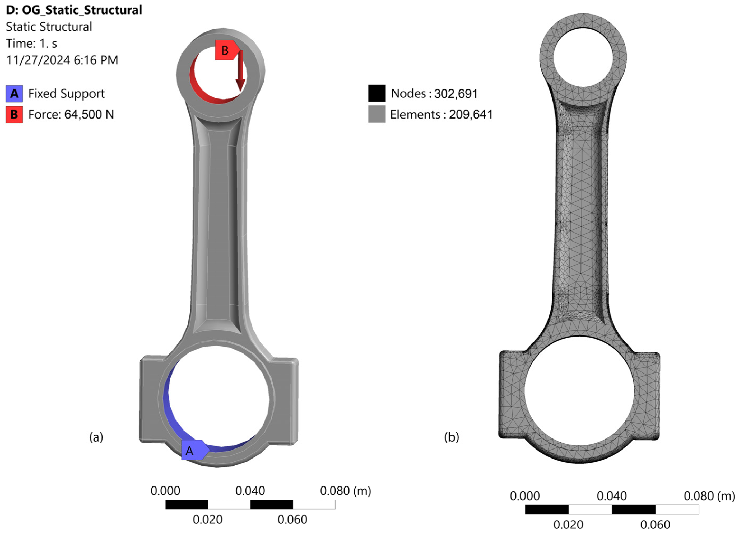
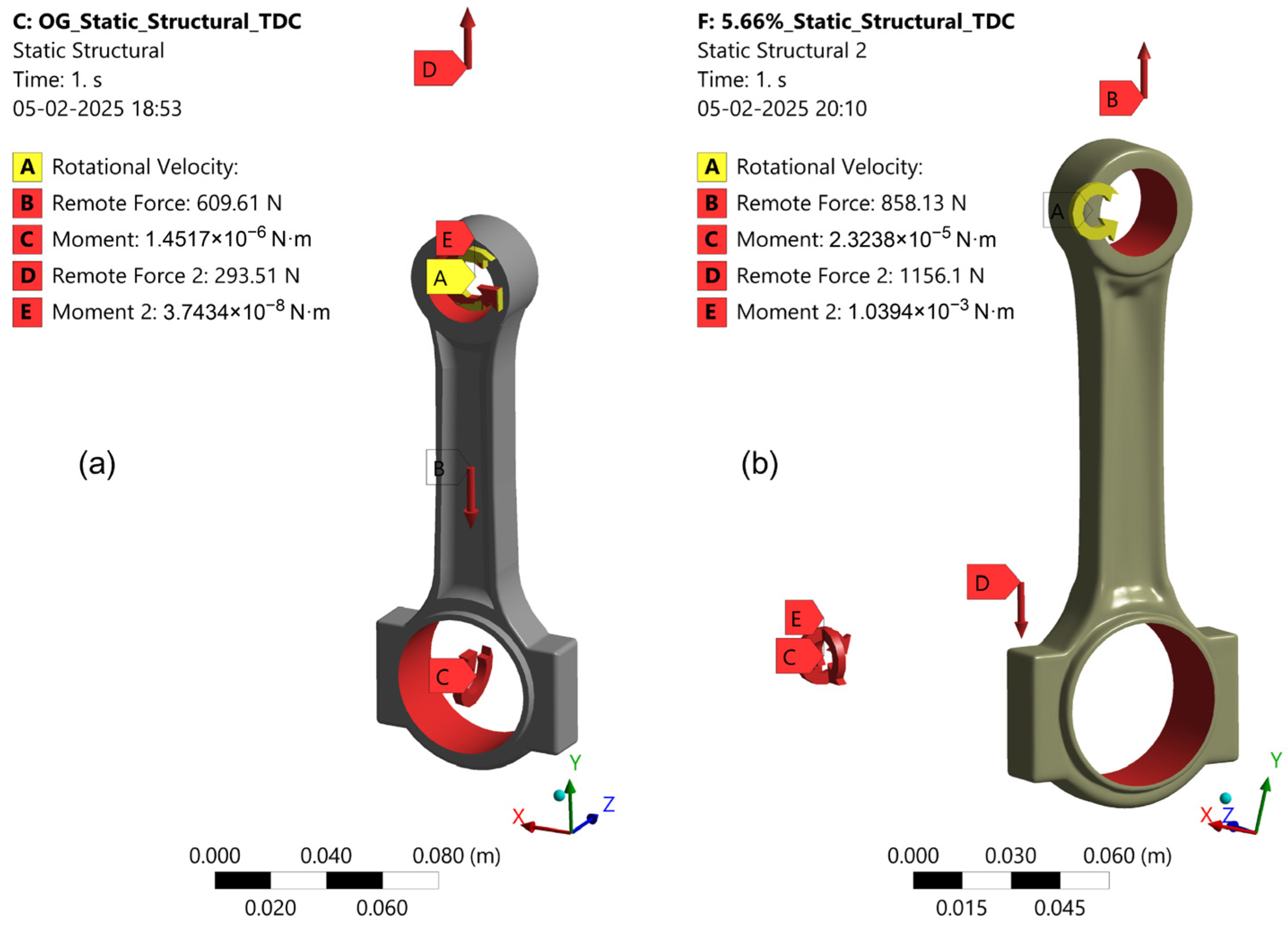
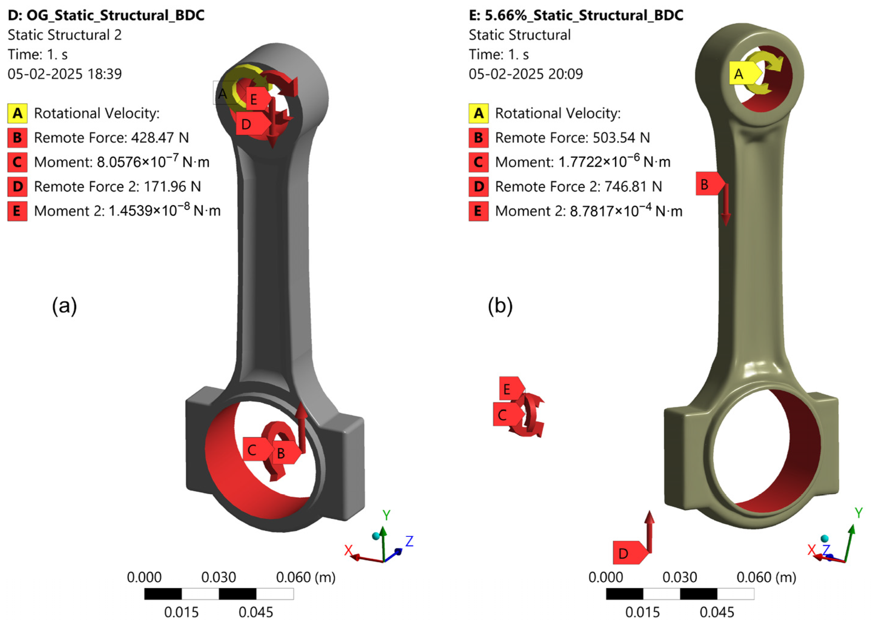
3.1. Static Structural Analysis

Static structural analysis was performed in the ANSYS workbench, and engineering data were added to the material library for the material 36MnVS4. Then, the initial connecting rod’s CAD model was imported into the ANSYS environment. Figure 4 shows the boundary conditions and mesh properties of the static structural analysis used in the initial design of the connecting rod. Mesh properties are important in structural analysis, as higher mesh resolution leads to more accurate simulation results [18]. As a boundary condition, the big end of the connecting rod was fixed, and a load of 64,500 N was applied to the small end as shown in Figure 4a. The mesh was then generated, as shown in Figure 4b.
Calculation of force acting on the piston due to combustion ( f C ) .
For gasoline engines, their maximum peak pressure is between 70 bar and 130 bar [19].
Assuming the peak pressure ( P ) as 125 bar for the gasoline engine, the area of the piston ( A ) was determined using a piston diameter ( d p ) of 81 mm in the following equation:
A = π × d p 2 2
The area of the piston ( A ) was therefore 0.005153 m2.
f C = P × A
f C = 64,412.5 64,500 N
The force acting on the piston due to combustion ( f C ) was 64,500 N.
As a boundary condition, the big end of the connecting rod was set as fixed, and the combustion force of 64,500 N was applied directly on the piston and carried to the small end of the connecting rod. When the combustion force was applied on the small end of the connecting rod, a buckling load acted on the shank part of the connecting rod as a result, causing it to experience compressive stress, which may have led to bending or deformation. Later, meshing was performed and 302,691 nodes with 209,641 elements were generated for a resolution of 5, slow transition, and fine span angle center as shown in Figure 4. Once the mesh was generated, the loading conditions were applied based on the peak pressure.
Based on the boundary conditions, the obtained maximum von Mises stress was 5.8556 × 10⁸ Pa and the maximum von Mises strain was 0.0028.

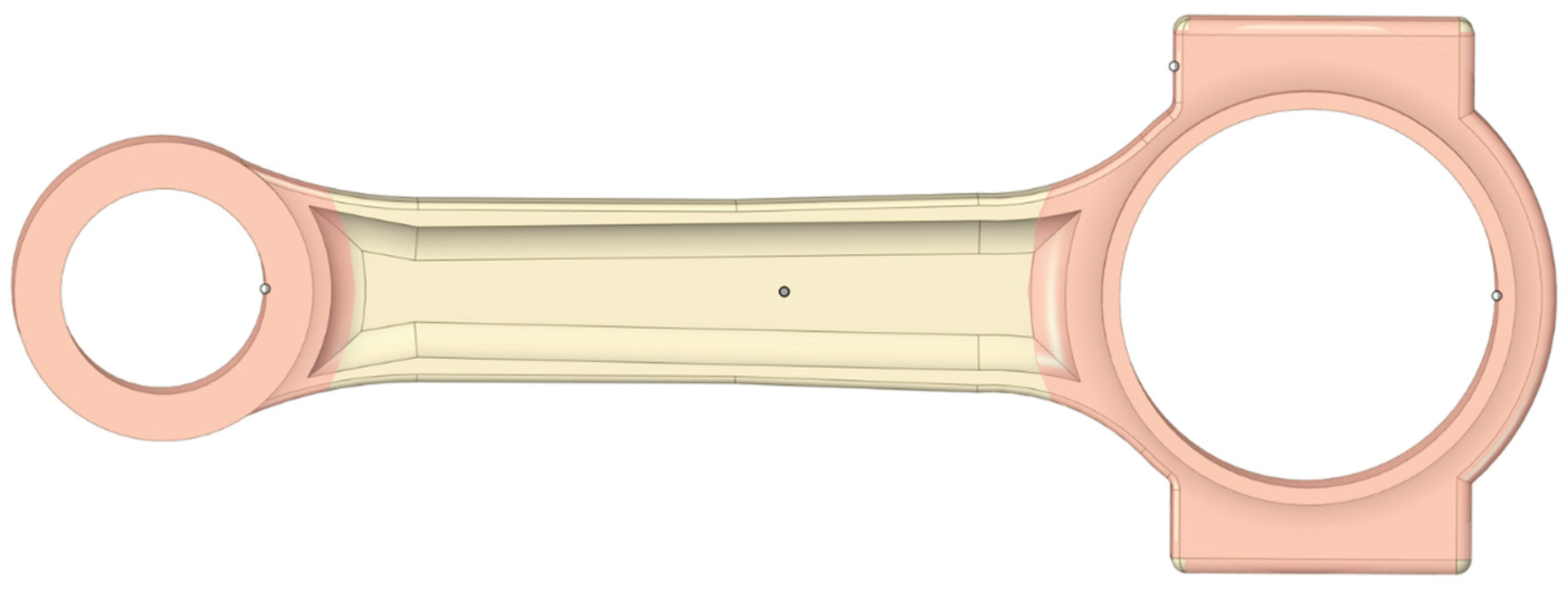
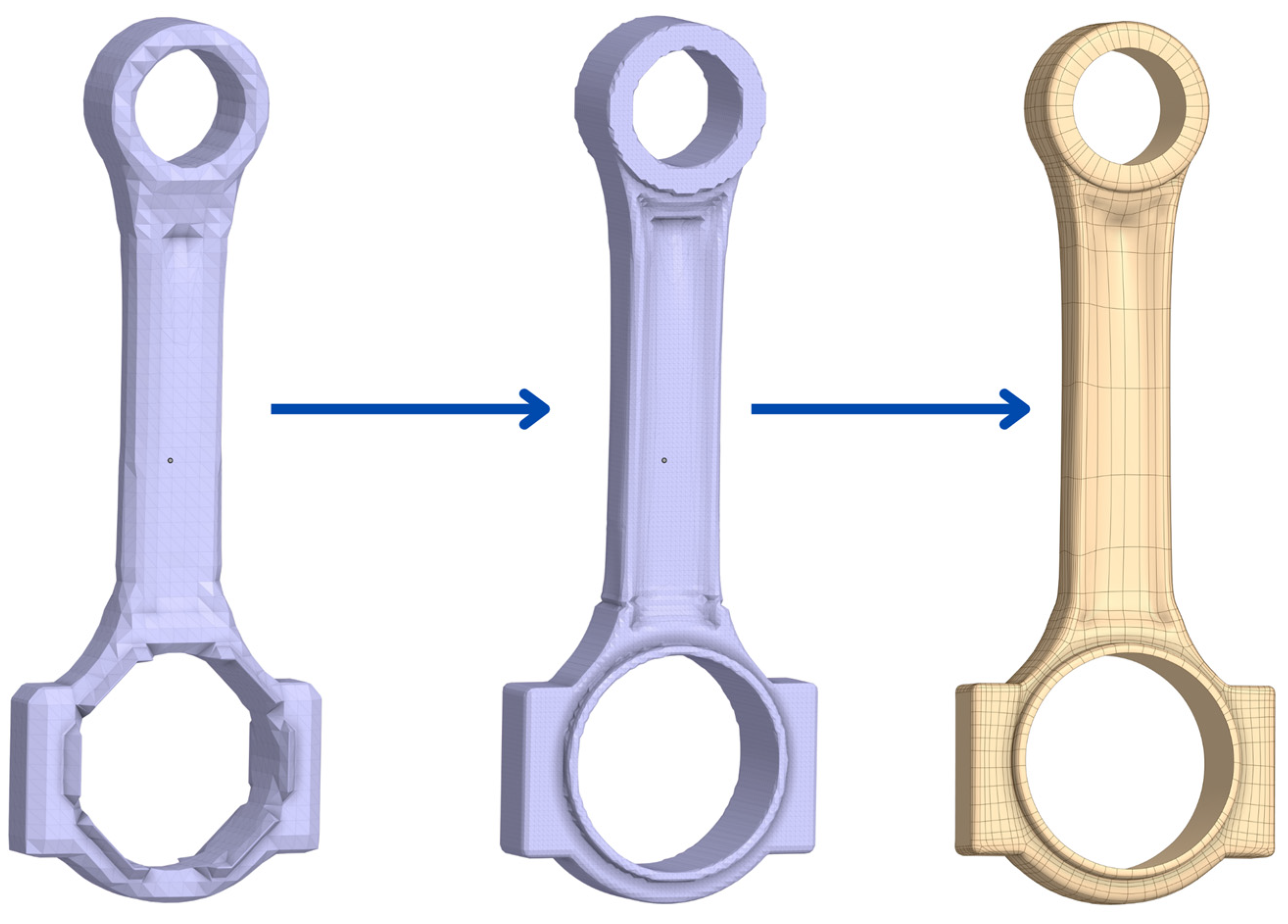
3.2. Topology Optimization

ANSYS Discovery software uses the Solid Isotropic Material with Penalization (SIMP) method. During the iteration process, the ANSYS Discovery solver adjusts the material density, ( ρ ) from 0 ( ρ ) to 1 within the permissible area outside the protected depth. Herein, if the material density ( ρ ) is equal to 1, it represents full material density, and if the ( ρ ) is equal to 0, it represents zero material density [20]. There are several options for the TO process in ANSYS Discovery, i.e., optimizing for the strength or response to free vibration, optimizing for a specified frequency, optimizing to minimize stress, and optimizing to minimize volume [21].
ρ = ρ p × K
where K denotes the real stiffness matrix of an element, and p denotes the factor of penalization [14,22].
The following targets were outlined for the TO process:
  • To reduce the mass at least by 3%;
  • To reduce the maximum von Mises stress and von Mises strain;
  • To define the protected depths at both ends of the connecting rod;
  • To maintain major dimensions;
  • To obtain a different cross-section than the I-Section;
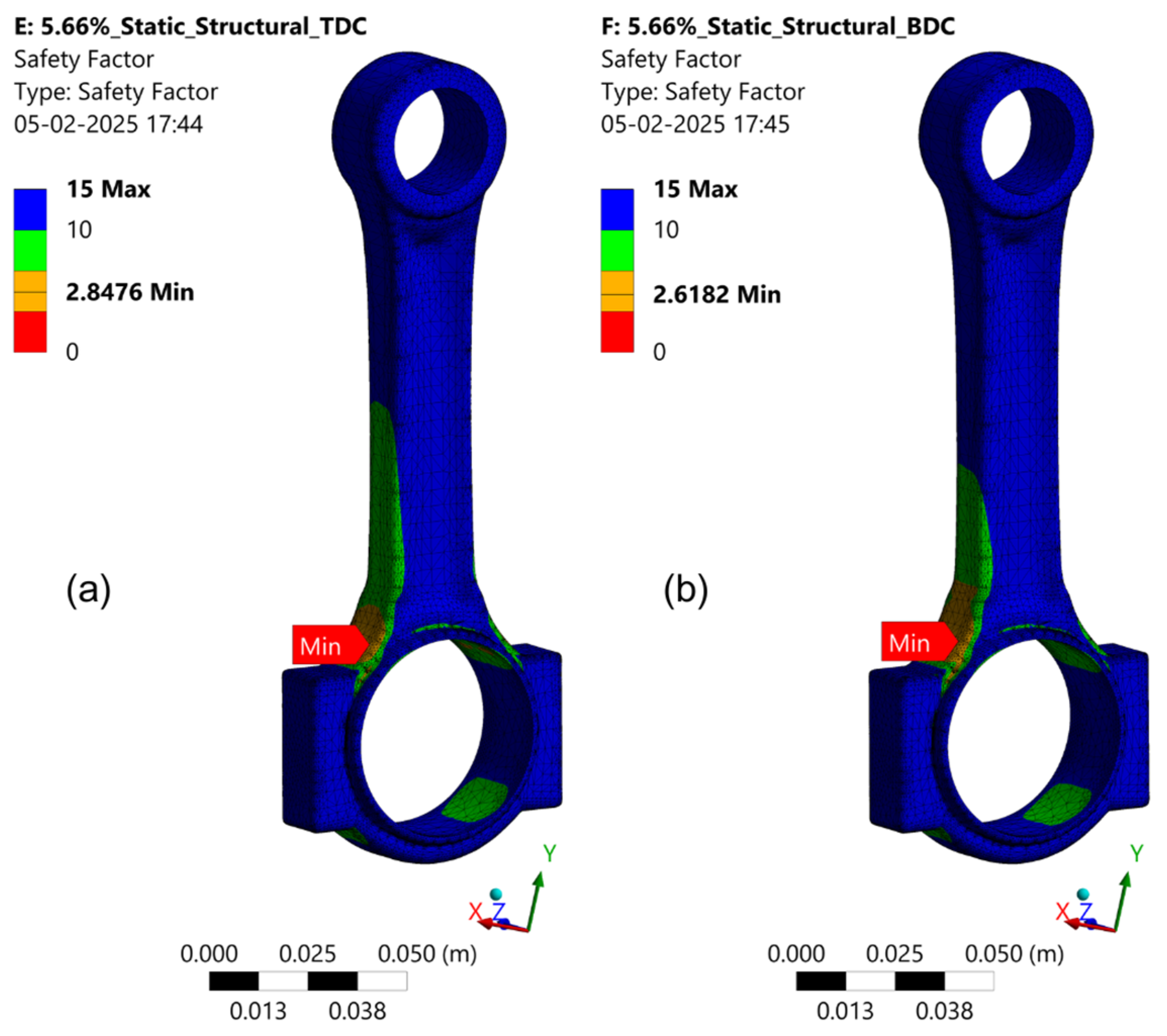
  • To keep the FOS above 2.5;
  • To manufacture the component in both additive manufacturing and conventional forging.
In this research, minimizing stress was set as the objective of the TO process. While setting the boundary conditions, the same conditions were used as in the static structural analysis, and by defining the protected depths of 0.012 m on both ends of the connecting rod, the TO process could be carried out as shown in Figure 5 [23]. The TO process was carried out at various target percentages from 3% to 5% to reduce the mass of the existing design [24].
Two of the important factors influencing the optimization process were the quality of the mesh and the number of elements. Once the topology was achieved, facets were created for that percentage of reduced mass, and we were required to clean up the facet design using the repair facet tool and subD hybrid option as shown in Figure 6, before exporting it as an STL or STEP file [25].
The goal of the TO in this study was to minimize mass while ensuring structural integrity by controlling the von Mises stress.
min ρ M ( ρ ) = ρ   d Ω
where ρ is the material density function,   M ( ρ ) is the total mass of the connecting rod, and Ω denotes the design domain.
min ρ σ m a x ( ρ )
where σ m a x is the maximum von Mises stress in the structure [26,27].
The connecting rod was subject to the following constraints.
The optimized design had to ensure that von Mises stress did not exceed an allowable limit:
σ m a x ( ρ )   σ a l l o w
To ensure structural safety, the minimum FOS had to be maintained as the following:
F O S = σ y i e l d σ m a x     2.5
As a boundary condition, the big end of the connecting rod was fixed, and force was applied to the small end of the connecting rod [28].
After solving the topology at various percentages on a trial-and-error basis, the results targeted at 4% mass reduction had a mass reduction of 5.66% with minimum von Mises stress compared to the targeted values of 3% and 5%. Figure 7a shows the original shape of the connecting rod, and Figure 7b shows the final optimized topology of the connecting rod with a 5.66% mass reduction and initial design.
The obtained topology had a 5.66% reduction in mass from 654 g to 618 g.

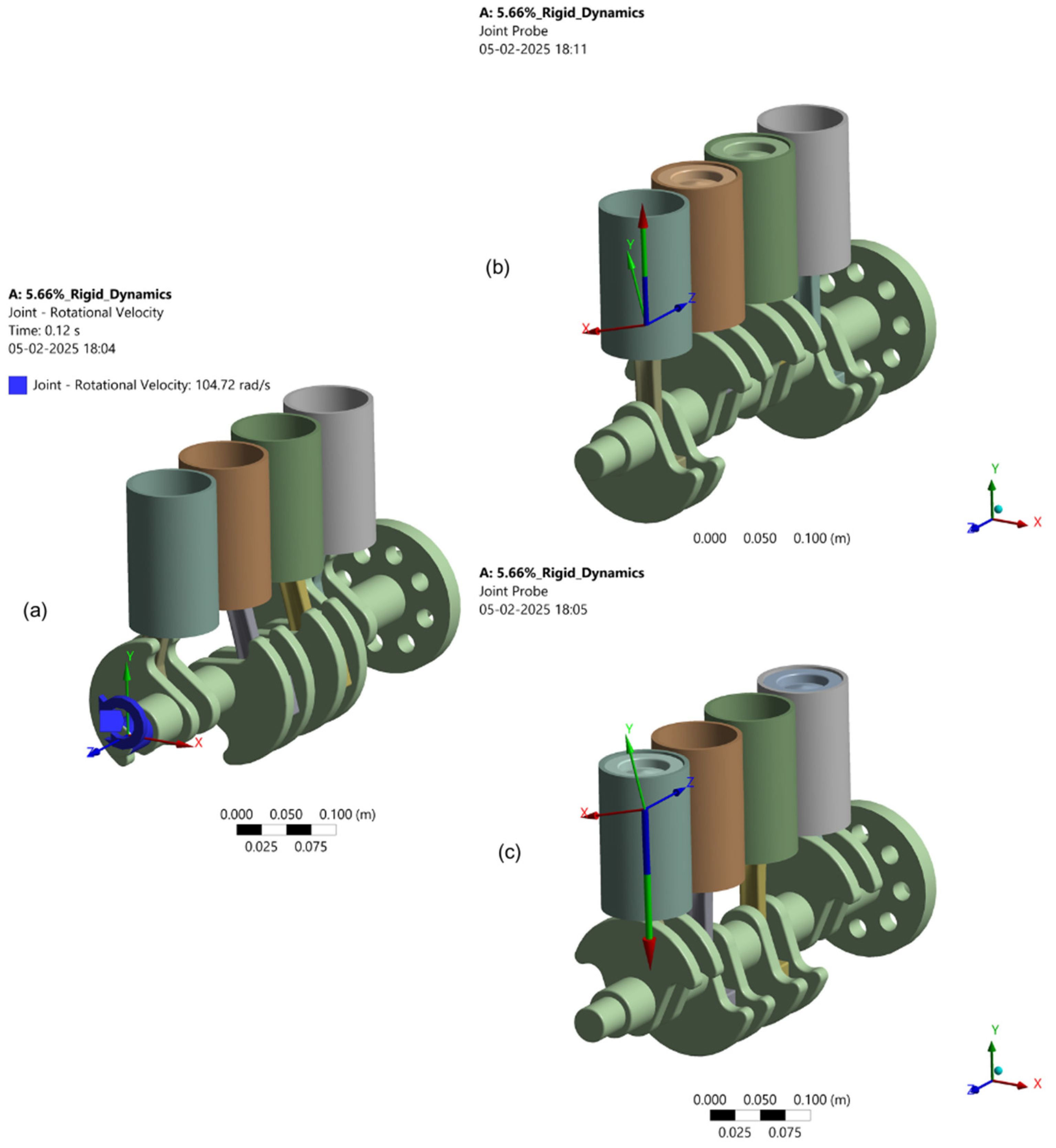
3.3. Dynamic Analysis

The objective of the dynamic analysis was to determine the unknown reaction forces and moments acting on the connecting rod while the engine was running at the speed of 1000 rpm. During the dynamic analysis, all the bodies were defined as rigid bodies and assembled using transitional, fixed, and revolute joints. The rotational velocity ( ω ) was determined based on the defined maximum rpm. For the speed of 1000 rpm, the rotational velocity is defined as
ω = R P M × 2 π 60 = 104.72   r a d / s
Once the connections were defined according to Table 3, the maximum unknown reaction forces acting on the connecting rod were probed using a joint probe in the solution section. Since all bodies were set as rigid, there was no meshing involved while determining the dynamic motion loads.
While constructing the assembly, it was important to calculate the total degree of freedom (DOF), by assuming the required kinematic motions for each part individually [29]. This assembly had 13 degrees of freedom, and it is explained below as shown in Table 3.
A rotational velocity ( ω ) of 104.72 rad/s was applied on the crankshaft as shown in Figure 8a. Once the motion study was completed, the maximum reaction loads as shown in Figure 8b,c were retrieved from the solution and exported as a text file to evaluate the reaction forces acting on the connecting rod in a separated static structural analysis.
From this study, the engine assembly had a good balance between the counterweight of the crankshaft and the newly obtained topology of the connecting rod, which is due to a minimum weight reduction and optimized topology. When the weight reduction was targeted at more than 7%, there was a noticeable imbalance and increase in vibration due to the connecting rod weight ratio and the counterweight of the crankshaft.

Motion Loads

Motion loads are the loads that are obtained from the motion of a mechanical system with certain allowable DOFs, such as inertial loads due to the mass of moving parts, impact loads due to sudden collisions, and dynamic loads from cyclic motion or vibrations, etc. In this study, motion loads were important since the engine underwent rapid tensile and compressive forces during cyclic motion along with inertial forces due to the motion of the crankshaft and connecting rod.
The obtained motion load from the rigid body dynamics was applied to a new static structural study, where the connecting rod was subjected to two reaction forces, and two tensile forces were applied simultaneously along with two reaction moments while moving toward the top dead center (TDC), as shown in Figure 9a,b.
These reaction force values as shown in Figure 9a explains When the connecting rod moved toward the TDC, there were remote forces of 609.61 N and 293.51 N acting as tensile forces, along with moments of 1.4517 × 10⁻⁶ Nm and 3.7434 × 10⁻⁸ Nm acting on the initial design of the connecting rod.
Figure 9b shows that when the connecting rod moved toward the TDC, there were remote forces of 858.13 N and 1156.1 N acting as tensile forces, along with moments of 2.3238 × 10⁻⁵ Nm and 1.0394 × 10⁻⁸ Nm acting on the optimized topology of the connecting rod with a mass reduction of 5.66%.
The forces obtained from the rigid body dynamics were applied to a new static structural study where the connecting rod was exposed to two compression forces at the same time as two reaction moments while it moved toward the bottom dead center (BDC), as shown in Figure 10a,b.
These reaction force values as shown in Figure 10a explains When the connecting rod moved toward the BDC, there were remote forces of 428.47 N and 171.96 N acting as compressive forces, along with moments of 8.0576 × 10⁻⁷ Nm and 1.4539 × 10⁻⁸ Nm acting on the initial design of the connecting rod.
Figure 10b shows that when the connecting rod moved toward the BDC, there were remote forces of 503.54 N and 746.81 N acting as compressive forces along with moments of 1.7722 × 10⁻⁶ Nm and 8.7817 × 10⁻⁴ Nm acting on the optimized topology of the connecting rod with a mass reduction of 5.66%.
These reaction force values show how the engine balance varied between the initial design of the connecting and optimized topology for 5.66% weight reduction. When the mass of the connecting rod was reduced by more than 7%, that may have caused a total imbalance between the counterweight of the crankshaft and the connecting rod, making the engine unstable by causing high vibrations. To avoid this problem, the ratio between the crankshaft counterweight and connecting rod should always be maintained.

4. Results

This section has two parts, wherein the first part explains the results obtained directly from the static structural analysis, and the second part discusses the verification of the optimized topology from the dynamic analysis.

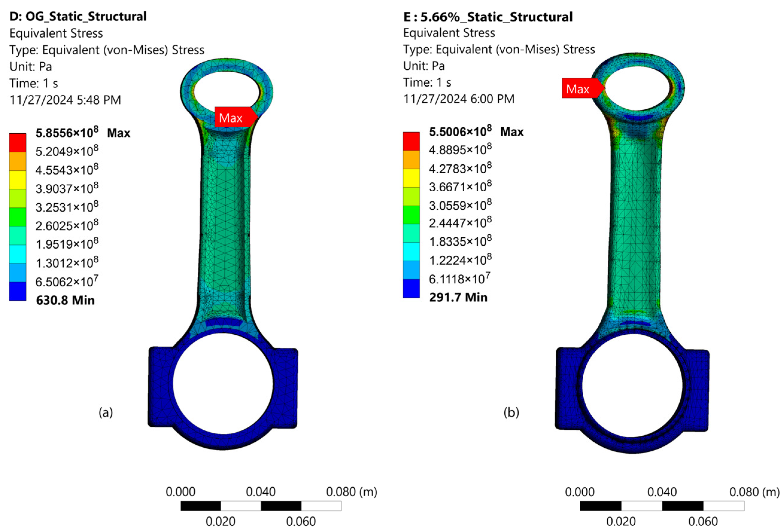
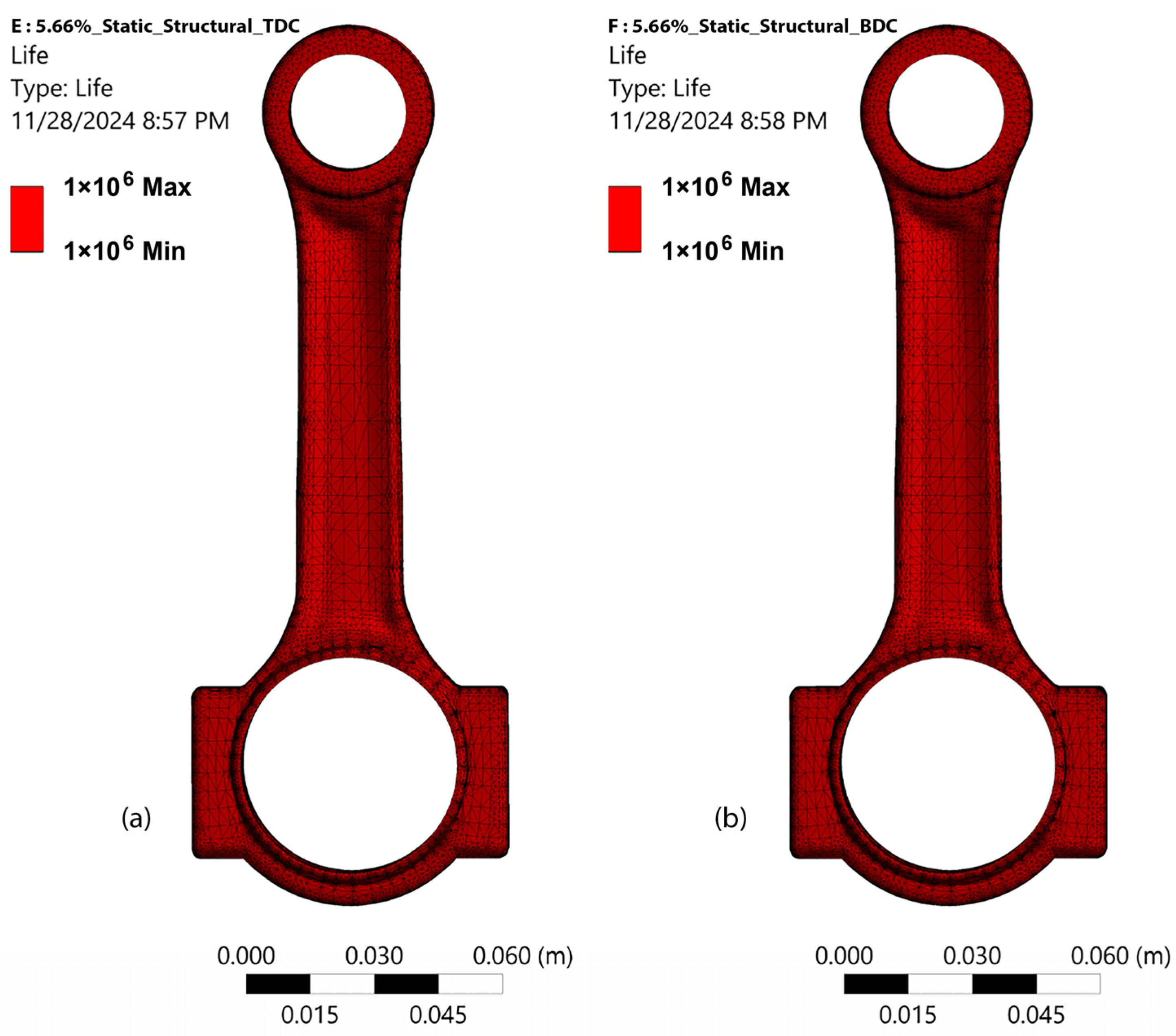
4.1. Results from Static Structural Analysis

The maximum von Mises stress obtained from the original topology for the applied load of 65 KN was 5.8556 × 10⁸ Pa, as shown in Figure 11a, while the minimum von Mises stress was 630.8 Pa, with an average von Mises stress of 6.3227 × 10⁷ Pa. Once the topology was optimized for the targeted 4%, the mass was originally reduced by up to 5.66% from 654 g to 618 g. The maximum von Mises stress obtained for the same load of 65 KN was 5.5006 × 10⁸ Pa, as shown in Figure 11b, and the minimum von Mises stress was 291.7 Pa, with an average von Mises stress of 1.3862 × 10⁸ Pa.

4.2. Results from Motion Loads

The dynamic study was carried out to extract the motion loads to evaluate the safety factor of the connecting rod. As discussed in Section 3, the connecting rod was subjected to simultaneously tensile and compressive loads, and only the maximum reaction forces acted while the connecting rod moving toward the TDC and BDC was evaluated. Goodman fatigue life analysis was used to evaluate the FOS and life of the connecting rod and verify that the optimized topology did not fail under the defined conditions. Based on the given reaction forces, the connecting rod had the lowest safety factors of 2.8476 and 2.6182 at the crank end while moving toward the TDC and BDC, respectively, as shown in Figure 12a,b. Given that the FOS needed to be more than 2.5 for the connecting rod, the results satisfied this condition since the obtained FOS values were above 2.5 even in the weaker nodes.
Goodman fatigue life analysis was used since the chosen material was alloy-steel and to predict the lifecycle of the connecting rod when it was subjected to varying stress [30].
Contributions of this research
  • The TO process of the connecting rod showed the possibilities of optimizing similar highly dynamic components.
  • An improvement in the existing design was achieved by reducing the mass by 5.66%.
  • The static structural results were validated by the dynamic analysis.
  • The obtained optimized topology was designed in such a way to make it possible to be produced by both conventional manufacturing methods like forging and additive manufacturing.
  • The combination of static structural analysis for the design and rigid body dynamics for the verification of the optimized design can be repeated and applied to similar studies.
The results clearly show that the connecting rod did not fail under the given motion load conditions while moving toward the TDC and BDC, even at 1 million cycles, as shown in Figure 13a,b.

5. Conclusions

This research aimed to optimize the topology of a connecting rod by reducing the mass of the component and minimizing the maximum von Mises stress. The optimization process included various procedures including static structural analysis and dynamic analysis for the validation of the FOS and the life of the connecting rod based on Goodman fatigue analysis. A motion study was carried out as part of the validation, where the maximum unknown reaction forces and moments acting on the connecting rod were evaluated while the connecting rod moved toward the TDC and BDC. The main obtained results were the following:
  • The topology of the connecting rod was optimized to 5.66% from 654 g to 618 g.
  • The maximum von Mises stress was reduced from 5.8556 × 10⁸ Pa to 5.5006 × 10⁸ Pa during static structural analysis.
  • The FOS was maintained above 2.6 during the dynamic analysis of the connecting rod.
As part of this study, it was also found that the excess reduction in the mass of the connecting rod had a direct effect on the stability of the engine. Hence, the weight ratio between the connecting rod and the counterweight of the crankshaft should be maintained.
A possible continuation of this research could be conducted by manufacturing the topology-optimized connecting rod using additive manufacturing or by other conventional methods and experimenting with different materials to improve the properties of the connecting rod. Later, the new connecting rod could be tested using the digital image correlation method (DIC) to validate the simulation results with the actual results.

Author Contributions

Conceptualization, M.N.R.; methodology, M.N.R.; software, M.N.R. and P.G.; validation, A.S. and A.N.; formal analysis, M.N.R.; investigation, M.N.R. and P.G.; data curation, M.N.R.; writing—original draft, M.N.R. and P.G.; writing—review and editing, M.N.R., A.S., and A.N.; visualization, M.N.R.; supervision, A.S.; project administration, M.N.R.; funding acquisition, A.S. All authors have read and agreed to the published version of the manuscript.

Funding

This work was supported in part by the Student Grant Competition project “Research, Development, and Innovation in the Field of Transport and Logistics 2025” financed by the Ministry of Education, Youth, and Sports and Faculty of Mechanical Engineering, Vysoka skola banska-Technical University of Ostrava (VSB-TUO), under SP2025/065; by the Materials and Technologies for Sustainable Development within the Jan Amos Komensky Operational Program financed by the European Union (EU) and the State Budget of Czech Republic under Grant No. CZ.02.01.01/00/22_008/0004631; and by the EU through REFRESH—Research Excellence For Region Sustainability and High-Tech Industries via the Operational Programme Just Transition Project No. CZ.10.03.01/00/22_003/0000048.

Institutional Review Board Statement

Not applicable.

Informed Consent Statement

Not applicable.

Data Availability Statement

The data presented in this paper can be made available on request from the corresponding author.

Acknowledgments

All authors have read and agreed to the published version of the manuscript. The authors would like to thank the Faculty of Mechanical Engineering and the Ph.D. Academy of Vysoka skola banska-Technical University of Ostrava (VSB-TUO) for their support during the computational study using Autodesk Inventor Professional 2025, ANSYS 2024 R2 and guidance with academic writing.

Conflicts of Interest

The authors declare no conflicts of interest.

Abbreviations

The following abbreviations are used in this manuscript:
TOTopology optimization
FOSFactor of safety
FEMFinite element method
RPMRevolutions per minute
CADComputer-aided design
ICInternal combustion
STEPStandard for the Exchange of Product
SIMPSolid Isotropic Material with Penalization
STLStereolithography
DOFDegree of freedom
TDCTop dead center
BDCBottom dead center
DICDigital image correlation

References

  1. Heywood, J.B. Internal Combustion Engine Fundamentals; McGraw-Hill: New York, NY, USA, 1988. [Google Scholar]
  2. J604D_197906; Engine Terminology and Nomenclature-General. SAE: Warrendale, PA, USA, 1979.
  3. Kocaaslan, O. Numerical investigation on pulse detonation engine performance under different equivalence ratio. Adv. Eng. Lett. 2024, 3, 1–12. [Google Scholar] [CrossRef]
  4. Decker, Ž.; Rudzinskas, V.; Drozd, K.; Caban, J.; Tretjakovas, J.; Nieoczym, A.; Matijošius, J. Analysis of the Vehicle Chassis Axle Fractures. Materials 2023, 16, 806. [Google Scholar] [CrossRef] [PubMed]
  5. Camba, J.D.; Contero, M.; Company, P. Parametric CAD Modeling: An Analysis of Strategies for Design Reusability. Comput.-Aided Des. 2016, 74, 18–31. [Google Scholar] [CrossRef]
  6. Rao, S.S. The Finite Element Method in Engineering; Butterworth-Heinemann: Oxford, UK, 2017. [Google Scholar]
  7. Gao, W.; Wang, G.; Zhu, J.; Fan, Z.; Li, X.; Wu, W. Structural Optimization Design and Strength Test Research of Connecting Rod Assembly of High-Power Low-Speed Diesel Engine. Machines 2022, 10, 815. [Google Scholar] [CrossRef]
  8. Shabana, A.A. Dynamics of Multibody Systems; Cambridge University Press: Cambridge, UK, 2013; ISBN 9781107042650. [Google Scholar]
  9. Caban, J.; Nieoczym, A.; Matijošius, J.; Kilikevičius, A.; Drozd, K. Analysis of the construction of the car trailer frame in terms of changing the assembly technology. Sci. J. Silesian Univ. Technol. Ser. Transp. 2024, 124, 47–61. [Google Scholar] [CrossRef]
  10. Wang, R.; Zhang, X.; Zhu, B.; Zhang, H.; Chen, B.; Wang, H. Topology Optimization of a Cable-Driven Soft Robotic Gripper. Struct. Multidiscip. Optim. 2020, 62, 2749–2763. [Google Scholar] [CrossRef]
  11. Okorie, O.; Perveen, A.; Talamona, D.; Kostas, K. Topology Optimization of an Aerospace Bracket: Numerical and Experimental Investigation. Appl. Sci. 2023, 13, 13218. [Google Scholar] [CrossRef]
  12. Mirzendehdel, A.M.; Behandish, M.; Nelaturi, S. Topology Optimization with Accessibility Constraint for Multi-Axis Machining. Comput.-Aided Des. 2020, 122, 102825. [Google Scholar] [CrossRef]
  13. Bendsøe, M.P.; Sigmund, O. Topology Optimization: Theory, Methods and Applications; Springer: Berlin/Heidelberg, Germany, 2004; ISBN 978-3-662-05086-6. [Google Scholar]
  14. Mikulikova, A.; Mesicek, J.; Karger, J.; Hajnys, J.; Ma, Q.-P.; Sliva, A.; Smiraus, J.; Srnicek, D.; Cienciala, S.; Pagac, M. Topology Optimization of the Clutch Lever Manufactured by Additive Manufacturing. Materials 2023, 16, 3510. [Google Scholar] [CrossRef] [PubMed]
  15. Richard van Basshuysen, F.S. Internal Combustion Engine Handbook: R-345: Basics, Components, Systems and Perspectives; SAE International: Warrendale, PA, USA, 2004. [Google Scholar]
  16. Kou, S.; Shi, Z.; Song, W. Fracture-Splitting Processing Performance Study and Comparison of the C70S6 and 36MnVS4 Connecting Rods. SAE Int. J. Engines 2018, 11, 463–474. [Google Scholar] [CrossRef]
  17. Yan, J.; Chen, L.; Zhang, C.; Miao, H.; Wang, S.; Wu, G.; Gao, J.; Wu, H.; Zhao, H. Influence of Sulfur on the Splitting Fracture and Machining Performance of Microalloyed Medium-Carbon Steel 36MnVS4 Connecting Rods. J. Mater. Eng. Perform. 2024, 33, 12125–12132. [Google Scholar] [CrossRef]
  18. Shaari, M.S.; Rahman, M.M.; Noor, M.M.; Kadirgama, K.; Amirruddin, A.K. Design of Connecting Rod of Internal Combustion Engine: A Topology Optimization Approach. In Proceedings of the National Conference in Mechanical Engineering Research and Postgraduate Studies, Kuantan, Pahang, Malaysia, 3–4 December 2010; pp. 155–166. [Google Scholar]
  19. Hamm, T.; Rebbert, M.; Ecker, H.-J.; Grafen, M. Cylinder Head Design for High Peak Firing Pressures. SAE Int. J. Engines 2008, 1, 746–755. [Google Scholar] [CrossRef]
  20. Bendsøe, M.P.; Kikuchi, N. Generating Optimal Topologies in Structural Design Using a Homogenization Method. Comput. Methods Appl. Mech. Eng. 1988, 71, 197–224. [Google Scholar] [CrossRef]
  21. Topology Optimization. Available online: https://ansyshelp.ansys.com/public/account/secured?returnurl=/Views/Secured/corp/v242/en/discovery/UDA/user_manual/physics/structural/topics/c_topo_intro.html (accessed on 3 October 2024).
  22. User Guide, Altair OptiStruct. Available online: https://2021.help.altair.com/2021/hwsolvers/os/topics/solvers/os/topology_opt_design_variables_r.htm (accessed on 10 October 2024).
  23. Setting the Protected Depth. Available online: https://ansyshelp.ansys.com/public/account/secured?returnurl=//////Views/Secured/corp/v242/en/discovery/UDA/user_manual/physics/structural/topics/t_topo_protect_distance.html (accessed on 24 September 2024).
  24. Topology Optimization Goals and Tool Options. Available online: https://ansyshelp.ansys.com/public/account/secured?returnurl=//////Views/Secured/corp/v242/en/discovery/UDA/user_manual/physics/structural/topics/r_structural_topo_tools.html (accessed on 12 September 2024).
  25. Creating the SubD Hybrid Model. Available online: https://ansyshelp.ansys.com/public/account/secured?returnurl=/Views/Secured/corp/v242/en/discovery/UDA/user_manual/modeling/facets/topics/t_autoskin_create_subd_hybrid.html?q=subD%20hybrid (accessed on 12 October 2024).
  26. Duysinx, P.; Bendsøe, M.P. Topology Optimization of Continuum Structures with Local Stress Constraints. Int. J. Numer. Methods Eng. 1998, 43, 1453–1478. [Google Scholar] [CrossRef]
  27. Senhora, F.V.; Giraldo-Londoño, O.; Menezes, I.F.M.; Paulino, G.H. Topology Optimization with Local Stress Constraints: A Stress Aggregation-Free Approach. Struct. Multidiscip. Optim. 2020, 62, 1639–1668. [Google Scholar] [CrossRef]
  28. Shigley, J.E.; Mischke, C.R. Standard Handbook of Machine Design; McGraw-Hil: New York, NY, USA, 1986. [Google Scholar]
  29. Xu, L.; Li, Q.; Zhang, N.; Chen, Q. Mobility, Kinematic Analysis, and Dimensional Optimization of New Three-Degrees-of-Freedom Parallel Manipulator With Actuation Redundancy. J. Mech. Robot. 2017, 9, 041008. [Google Scholar] [CrossRef]
  30. Rice, R.C. SAE Fatigue Design Handbook AE-22; SAE International: Warrendale, PA, USA, 1997. [Google Scholar]
Figure 1. Major dimensions of the connecting rod’s initial design.
Applsci 15 02081 g001
Figure 2. Virtual assembly of the crankshaft, connecting rod, piston, and cylinder liner.
Applsci 15 02081 g002
Figure 3. Topology optimization and validation process workflow.
Applsci 15 02081 g003
Figure 4. (a) Boundary conditions applied during the static structural analysis in the initial design. (b) Mesh properties used during the static structural analysis in the initial design.
Applsci 15 02081 g004
Figure 5. Protected depth of 0.012 m on both ends of the connecting rod.
Applsci 15 02081 g005
Figure 6. The sequence of the connecting rod TO from initial facets to the final subD hybrid conversion.
Applsci 15 02081 g006
Figure 7. (a) Original shape of the connecting rod. (b) 5.66% reduced mass from the original shape of the connecting rod.
Applsci 15 02081 g007
Figure 8. (a) Boundary conditions—A rotational velocity of 104.72 rad/s was applied to the crankshaft. (b,c) Maximum unknown reaction forces extracted using a joint probe while the piston was moving toward the top dead center and the bottom dead center.
Applsci 15 02081 g008
Figure 9. (a) Maximum unknown reaction forces applied during static structural analysis on the initial design while at the TDC. (b) Maximum unknown reaction forces applied during static structural analysis on the optimized topology with a mass reduction of 5.66% while at the TDC.
Applsci 15 02081 g009
Figure 10. (a) Maximum unknown reaction forces applied during static structural analysis on the initial design while at the BDC. (b) Maximum unknown reaction forces applied during static structural analysis on the optimized topology with a mass reduction of 5.66% while at the BDC.
Applsci 15 02081 g010
Figure 11. (a) Maximum von Mises stress acting on the initial design. (b) Maximum von Mises stress acting on the 5.66% mass-reduced optimized topology.
Applsci 15 02081 g011
Figure 12. (a) Safety factor after applying the motion loads on the 5.66% mass-reduced optimized topology at the TDC. (b) Safety factor after applying the motion loads on the 5.66% mass-reduced optimized topology at the BDC.
Applsci 15 02081 g012
Figure 13. (a) Life of the connecting rod after applying the motion loads on the 5.66% mass-reduced optimized topology at the TDC. (b) Life of the connecting rod after applying the motion loads on the 5.66% mass-reduced optimized topology at the BDC.
Applsci 15 02081 g013
Table 1. Properties of 36MnVS4 [16].
Yield StrengthTensile StrengthDensityModulus of ElasticityPoisson’s Ratio
800 MPa1000 MPa7.85 g/cm3210 GPa0.29
Table 2. Assumed engine parameters for the initial design of the connecting rod.
Engine TypeCylinder BoreStroke LengthEngine Speed
Inline 4-cylinder81 mm82.25 mm1000 rpm (Max)
Table 3. Connections used in the engine assembly.
Connections Between the PartsJoints UsedDegrees of Freedom
Cylinder liners to groundFixed joint0 DOF
Crankshaft to groundFixed revolute joint1 DOF
Cylinder to pistonTransitional joint4 (x-axis)
Piston to connecting rodRevolute joint ( 2 )   × 4 DOFs
Connecting rod to crankshaftRevolute joint ( 2 )   × 4 DOFs
Disclaimer/Publisher’s Note: The statements, opinions and data contained in all publications are solely those of the individual author(s) and contributor(s) and not of MDPI and/or the editor(s). MDPI and/or the editor(s) disclaim responsibility for any injury to people or property resulting from any ideas, methods, instructions or products referred to in the content.

