Article

Event-Triggered MFAILC Bipartite Formation Control for Multi-Agent Systems Under DoS Attacks

Faculty of Information Engineering and Automation, Kunming University of Science and Technology, Kunming 650500, China
*
Author to whom correspondence should be addressed.
Appl. Sci. 2025, 15(4), 1921; https://doi.org/10.3390/app15041921
Submission received: 18 January 2025 / Revised: 10 February 2025 / Accepted: 10 February 2025 / Published: 12 February 2025
(This article belongs to the Topic Agents and Multi-Agent Systems)

Abstract

:
For multi-input multi-output (MIMO) nonlinear discrete-time bipartite formation multiagent systems (BFMASs) performing trajectory tracking tasks with unknown dynamics, a dynamic event-triggered model-free adaptive iterative learning control (DET-MFAILC) algorithm is proposed to address periodic denial-of-service (DoS) attacks. First, using the pseudo-partial derivative, a compact format dynamic linearization (CFDL) method is employed to construct an equivalent CFDL data model for the MIMO multi-agent system. A DoS attack model and its corresponding compensation algorithm are developed, while a dynamic event-triggered condition is designed considering both the consensus error and the tracking error. Subsequently, the proposed DoS attack compensation algorithm and the dynamic event-triggered mechanism are integrated with the model-free adaptive iterative learning control algorithm to design a controller, which is further extended from fixed-topology systems to time-varying topology systems. The convergence of the control system is rigorously proven. Finally, simulation experiments are conducted on bipartite formation multi-agent systems (BFMASs) under fixed and time-varying communication topologies. The results demonstrate that the proposed algorithm effectively mitigates the impact of DoS attacks, reduces controller updates, conserves network resources, and ensures that both the tracking error and consensus error converge to an ideal range close to zero within a finite number of iterations while maintaining a good formation shape.

1. Introduction

The control of a single agent is no longer sufficient to meet the demands of complicated activities due to the recent rapid development of agent applications in a variety of industries. As a result, multi-agent systems (MASs) formation control has attracted significant attention from scholars and researchers. MASs are widely applied to collaboratively accomplish various complex tasks, such as target tracking [1], UAV swarm missions [2], and environmental detection [3]. Formation control is one of the core functions of MASs, with the primary objective of controlling multiple agents to form a specific formation for cooperative operations. Currently, increasing research efforts have been directed toward formation control, leading to numerous achievements. For example, ref. [4] studies formation control for quadrotor UAVs, while ref. [5] discusses formation control for underwater vehicles.
It is worth noting that most existing studies adopt model-based control (MBC) methods to address such problems, requiring an accurate mathematical model of the MASs and assuming that all agents have identical structures. However, in practice, obtaining the plant’s accurate mathematical models is challenging, and MASs often consist of heterogeneous agents operating in complex environments with numerous uncertainties. Therefore, MBC methods are difficult to generalize and apply to practical systems. To address this challenge, data-driven control (DDC) methods have gained increasing attention, as they avoid the need for accurate data models. Various DDC approaches have emerged, such as reinforcement learning control [6], model-free adaptive control (MFAC) [7,8,9], and iterative learning control (ILC) [10,11,12]. Among these methods, MFAC designs controllers are solely based on the input/output (I/O) data of the controlled system, without requiring implicit or explicit system models, making it particularly suitable for heterogeneous MASs.
The model-free adaptive iterative learning control (MFAILC) method combines MFAC and ILC and is effective for controlling unknown nonlinear non-affine systems with repetitive operations. This method ensures monotonic convergence of system output errors along the iteration axis. Ref. [13] studies a bipartite formation event-triggered control scheme for single-input single-output (SISO) systems, introducing an observer to estimate outputs and designing event-triggered conditions based on the difference between observed and actual outputs. Ref. [14] employs the matrix transformation and the property of the nonnegative matrix, guaranteeing the iterative asymptotic convergence of the error of the SISO-type MASs under the structurally balanced digraph with an oriented spanning tree.
Moreover, information exchange between agents relies on network communication. The stability and security of formation systems are now significantly impacted by network attacks due to the rapid growth of network technology. Information transmission channels between agents often experience instability and physical limitations, making MASs susceptible to various network attacks, such as denial-of-service (DoS) attacks, deception attacks, and replay attacks [15,16,17]. Among these, DoS attacks are the most common, causing system instability or even loss of control. Therefore, addressing formation control problems under network attacks has become a research hotspot for MASs. Event-triggered mechanisms, which update the controller only when certain triggered conditions are met, can significantly reduce communication burdens and computational pressure [18], thereby alleviating the impact of DoS attacks to some extent. However, they cannot entirely eliminate the adverse effects caused by DoS attacks. Ref. [19] proposes a resilient event-triggered mechanism that effectively mitigates periodic DoS attacks while conserving network resources. In order to lessen the impact of DoS attacks, Zhao [20] suggests a hierarchical resilient learning technique and creates a virtual reference signal for every agent to estimate the time-varying reference signal. Additionally, ref. [21] presents an attack detection mechanism and buffer-based compensation strategies to address the adverse effects of DoS attacks. Designing more effective compensation strategies to minimize or eliminate the impact of DoS attacks remains an important research challenge.
The bipartite formation trajectory tracking problem for unknown non-affine nonlinear MASs that are subject to recurring DoS attacks is discussed in this study. The following is a summary of this work’s primary contributions:
1.
For MIMO heterogeneous multi-agent bipartite formation systems with unknown dynamics, a controller is designed based on the MFAILC method.
2.
To address the impact of periodic DoS attacks on MIMO heterogeneous MASs, a DoS attack compensation mechanism is introduced within the MFAILC framework to mitigate the effects of such attacks.
3.
An improved dynamic event-triggered mechanism is proposed, which incorporates both consensus error and tracking error into the dynamic triggered condition. Compared to the event-triggered conditions in ref. [22], the proposed mechanism significantly reduces controller updates, alleviates communication and computational pressure, and further enhances the system’s resilience against DoS attacks.
This is how the remainder of the paper is structured: Graph theory and modeling of periodic DoS attacks are introduced in Section 2. The controller design is detailed in Section 3. The system stability analysis and dynamic event-triggered mechanism are discussed in Section 4. Section 5 reports the simulation experiments. Finally, the conclusions are summarized in Section 6.

2. Preliminaries and Problem Formulation

2.1. Algebraic Graph Theory

Graph theory is an effective tool for describing the communication relationships among agents in MASs. Taking Figure 1 as an example, it illustrates the communication topology among the agents. The communication topology of this system can be represented as a directed graph G ¯ = ( V ¯ , E ¯ , A ) . V ¯ = V { 0 } presents the node set of the directed graph G ¯ , where V = { 1 , 2 , , N } , N represents the number of agents, and V consists of two subsets V 1 and V 2 , satisfying V = V 1 + V 2 and V 1 V 2 . E ¯ V ¯ × V ¯ denotes the edge set of the directed graph G ¯ . As shown in Figure 1, the topology represents a bipartite Formation Multi-Agent System (BFMAS). The direction of information flow between nodes is indicated by the arrows. Nodes within the same subset are considered to have a cooperative relationship, and the information flow arrows for such nodes are colored black. Conversely, nodes in different subsets are regarded as having a competitive relationship, and the arrows indicating information flow between these nodes are colored red. In the adjacency matrix A, the diagonal elements a p p = 0 , while the off-diagonal elements a p j are determined by the relationship between the nodes and their respective subsets. If node p can receive signals from node j and both nodes belong to the same subset, then a p p = 1 . If the two nodes belong to different subsets, then a p p = 1 . If there is no information flow between the two nodes, a i j = 0 . The Laplacian matrix of the directed graph G ¯ can be expressed as L A = B A , L | A | = B A . Here, B = d i a g ( b 1 , b 2 , , b N ) , b p = j = 1 N | a p j | . Therefore, matrix δ = diag ( δ 1 , δ 2 , , δ N ) is defined to describe the subset attributes of node p V . For example, when node p V , δ p = 1 ; if node p V 2 , δ p = 1 .
For leaderless BFMASs, each agent adjusts its state solely based on the information from its neighboring agents, without a clear goal. This may lead to local optimal solutions or chaotic movements among the agents. Introducing a virtual leader as a reference point can provide a common goal or direction for all agents, enabling better coordination. In Figure 1, node 0 represents the virtual leader. The connection matrix D = d i a g ( d 1 , d 2 , , d N ) describes the information flow between the virtual leader and the agents. If node p can receive signals from the virtual leader, d p = 1 ; otherwise, d p = 0 .
Furthermore, for BFMASs with time-varying and switching communication topologies, the time-varying communication topology can be described by a directed graph G ¯ ( k ) = ( V ¯ ( k ) , E ¯ ( k ) , A ( k ) ) . Here, G ¯ ( k ) = G ¯ t = { G ¯ 1 , G ¯ 2 , } represents all possible communication topologies of the BFMAS. The Laplacian matrix of the directed graph G ¯ ( k ) is denoted as L A ( k ) = B ( k ) A ( k ) , where A ( k ) = a p , j t ( k ) R N × N , B ( k ) = d i a g ( b 1 t ( k ) , b 2 t ( k ) , , b N t ( k ) ) and D ( k ) = d i a g ( d 1 ( k ) , d 2 ( k ) , , d N ( k ) ) is the connection matrix between the virtual leader and the agents.

2.2. Problem Formulation

For the repeatedly operated BFMASs, a multi-input multi-output (MIMO) agent p can be described as a nonlinear system as follows:
y p ( k + 1 , i ) = f p ( y p ( k , i ) , , y p ( k n y , i ) , u p ( k , i ) , u p ( k n u , i ) ) ,
here, k represents the sampling instant k [ 0 , 1 , , T ] , p = 1 , 2 , , N , where N is the number of agents. n y and n u are unknown positive integers, y p ( k , i ) R n and u p ( k , i ) R n are the system output and the control input of agent p in the i t h iteration and the sampling instant k, respectively. f ( ) denotes an unknown nonlinear function.
To obtain the equivalent linearized model of the MASs, the assumptions are as follows:
Assumption 1.
f ( ) has a continuous partial derivative with regard to u p ( k , i ) , i.e., ( f ( ) ) / ( u p ( k , i ) ) exists and is continuous.
Assumption 2.
For all and, if, then the generalized Lipschitz condition holds for Equation (1) in the iterative domain, i.e.,
Δ y p ( k + 1 , i ) b Δ u p ( k , i )
here, Δ y p ( k + 1 , i ) = y p ( k + 1 , i ) y p ( k + 1 , i 1 ) and Δ u p ( k , i ) = u p ( k , i ) u p ( k , i 1 ) . Both Δ y p ( k + 1 , i ) and Δ u p ( k , i ) are bounded, and b is a finite constant.
Assumption 3.
The communication topology G ¯ or G ¯ t of the MASs is strongly connected, meaning that each agent has a communicable path to the virtual leader.
Remark 1.
For many practical control systems, Assumptions 1 and 2 are reasonable. Assumption 1 represents a typical constraint imposed on general nonlinear systems in control system design. Assumption 2 imposes an upper limit on the rate of change of the system output caused by variations in the control input along the iterative axis. These assumptions have also been discussed in the literature, such as [12,13,23].
Theorem 1.
For the agent described in system (1) that satisfies Assumptions 1 and 2, when Δ u p ( k , i ) 0 , there must exist a time-varying pseudo-Jacobian matrix (PJM) Φ p ( k , i ) associated with the iterative axis, such that the agent can be equivalently represented by the following compact-form dynamic linearization (CFDL) data model:
Δ y p ( k + 1 , i ) = Φ p ( k , i ) Δ u p ( k , i )
Here, Φ p ( k , i ) as below
Φ p ( k , i ) = ϕ p , 11 ( k , i ) ϕ p , 1 m ( k , i ) ϕ p , m 1 ( k , i ) ϕ p , m m ( k , i ) R m × m
Moreover, Φ p ( k , i ) b ¯ , p [ 1 , 2 , , N ] , b ¯ denotes a positive constant.
Consequently, the following linearized model can be used to rewrite the relationship between the nonlinear agent p’s system input and output:
y p ( k + 1 , i ) = y p ( k + 1 , i 1 ) + Φ p ( k , i ) Δ u p ( k , i )
For the agent p in Equation (1), the trajectory of the virtual leader is considered as the reference output curve, denoted by y d ( k ) , where k { 0 , 1 , 2 , , T } represents the leader’s position at time k. Considering that there exists a distance gap between the followers and the leader in the formation system, the tracking error of agent p in the bipartite formation system is defined as:
e p ( k , i ) = y d ( k ) δ p ( y p ( k , i ) y ˜ p ( k ) )
In the above equation, y ˜ p ( k ) is the relative distance between agent p and the virtual leader, y p ( k , i ) is the output of the each agent, and δ p represents the node attribute of agent p in the communication topology graph, i.e., the membership indicator of agent p in the subset. The tracking error serves as a response to the agents’ ability to track in accordance with their individual desired curves. Then, the distributed formation error of agent p in the bipartite formation system is defined as:
ξ p ( k , i ) = j N p a p j ( y ¯ j ( k , i ) s g n ( a p j ) y ¯ p ( k , i ) ) + d p ( y d ( k ) s g n ( d p ) y ¯ p ( k , i ) )
here, j N p represents the neighboring agents of agent p, and a p j { 1 , 0 , 1 } indicates whether there is a competitive or cooperative relationship between agent p and agent j. d p indicates if agent p is able to obtain information from the virtual leader y d ( k ) . The system’s agents’ ability to maintain consensus and complete the task can be determined by the formation error.

3. Design of the Controller Scheme

3.1. Modeling of Periodic DoS Attacks

Due to the inherent unreliability of the information transmission channels between multiple agents, the system is prone to being affected by DoS attacks during the information transmission process. Generally speaking, DoS attacks are divided into two types: attacks on individual agents within the multi-agent system and attacks on the communication channels between the agents. This paper primarily focuses on the latter and assumes that the DoS attack is energy-constrained and periodic. The attacker performs attacks on the communication channels between the multi-agent system during the attack period, while reserving energy during the dormant period for the next attack. For each iteration, the attacker’s attack period is within k { 0 , 1 , 2 , , T } , as shown in Figure 2.
In Figure 2, k h o n is the start time of the attack in the attack period h t h , and k h o f f is the end time of the attack in the attack period h t h . The time interval k [ k h 1 o f f , k h o n ) is defined as the attack period when the DoS attacker is actively attacking, and the time interval k [ k h o n , k h o f f ) is defined as the dormant period when the DoS attacker is resting. For the data transmission process in the BFMASs, the dormant period of the attacker is defined as α p ( k , i ) = 0 , and the attack period is defined as α p ( k , i ) = 1 , where:
α p ( k , i ) = 0 , if k [ k h 1 o f f , k h o n ) , 1 , if k [ k h o n , k h o f f )
In MASs under periodic DoS attacks, the probability of successful data transmission between agents follows a Bernoulli distribution. Let β α p ( k , i ) represent the success or failure of data transmission between agents. A successful data transmission is indicated by β α p ( k , i ) = 1 , whereas a failure data transfer is shown by β α p ( k , i ) = 0 . The probability of successful transmission is denoted as P ( β α p ( k , i ) = 1 ) = β ¯ α p , and the probability of transmission failure is P ( β α p ( k , i ) = 1 ) = 1 β ¯ α p .
To reduce the influence of DoS attack, a DoS attack compensation is designed as below:
ξ α p ( k , i ) = β α p ( k , i ) ξ p ( k , i ) + ( 1 β α p ( k , i ) ) ξ p ( k , i 1 )
Remark 2.
The two primary components of the attack compensation system are ξ p ( k , i ) and ξ p ( k , i 1 ) . If information transmission fails, the distributed formation error of agents is denoted as ξ a p ( k , i ) = ξ p ( k , i 1 ) . In this case, the controller will use the most recent data received stored in the buffer ξ p ( k , i 1 ) to compensate for the effects of the DoS attack.

3.2. Design of the Dynamic Event-Triggered Mechanism

To lessen the strain of communication amongst agents in BFMASs and effectively conserve communication resources, an event-triggered mechanism is used to decrease the update frequency of control inputs. This is an effective approach.
Considering the effects of both the formation error and tracking error, the DET conditions are designed as follows:
S p k , i = κ Π p k , i + ϑ ξ a p k + 1 , i 1 ξ a p k + 1 , i s e p k + 1 , i 1
where ξ a p ( k + 1 , i s ) is the formation error of agent p recorded during the i s iteration, ξ a p k + 1 , i 1 is the formation error from the previous iteration, and κ > 0 , ϑ is a small positive constant.
The dynamic variant Π p k , i is defined as follows:
Π p k , i + 1 = κ Π p k , i + ϑ ξ a p k + 1 , i 1 ξ a p k + 1 , i s e p k + 1 , i 1
i s denotes the number of iterations when the event is triggered, which is obtained by the following equation:
i s + 1 = Δ inf { i Z + i > i s , S p ( k , i ) < 0 }
The convergence proof of the event-triggered condition is provided below.
Since S p ( k , i ) 0 , it follows from Equation (9) that
κ Π p k , i + ϑ ξ a p k + 1 , i 1 ξ a p k + 1 , i s + e p k + 1 , i 1
Taking the norm on both sides of Equation (10), we obtain:
Π p k , i + 1 κ Π p k , i + ϑ + ξ a p k + 1 , i 1 ξ a p k + 1 , i s + e p k + 1 , i κ Π p k , i + ϑ + κ Π p k , i + ϑ 2 κ Π p k , i + 2 ϑ ( 2 κ ) i Π p k , 1 + 2 ϑ 1 κ i 1 κ
Let κ ( 0 , 0.5 ) and S p ( k , i ) 0 ; there exists a constant r R + such that Π p k , i + 1 < r . Thus, lim i Π p k , i + 1 < 2 ϑ 1 κ .

3.3. Design of the MFAILC Controller Based on the Event-Triggered Mechanism

For the BFMASs, based on the CFDL data model (4) of agent p and the formation error ξ p ( k , i ) , the control update law is defined as follows [24]:
u p ( k , i ) = u p ( k , i 1 ) + ρ Φ p T ( k , i ) λ s + Φ p ( k , i ) 2 ξ p ( k + 1 , i 1 )
According to Equations (8) and (14), combined with S p < 0 , this satisfies the event-triggered condition and the iteration sequence satisfying the event-triggered condition is recorded. Considering that Φ p ( k , i ) is difficult to obtain directly, its estimated value Φ ^ p ( k , i ) is used as a substitute. Incorporating the event-triggered mechanism, a further rewrite of the control input update law (14) is as follows:
u p ( k , i s + 1 ) = u p ( k , i s ) + ρ p Φ ^ p T ( k , i s + 1 ) λ p + Φ ^ p ( k , i s + 1 ) 2 ξ a p ( k + 1 , i s + 1 ) , i = i s + 1 u p ( k , i s ) , i s i < i s + 1
Here, ρ p is the step factor and λ p is the weight factor. The parameter λ p has a large impact on the algorithm; the smaller the λ p , the faster the system responds while the amount of overshooting is larger. Conversely, the slower the response of the system, the smaller the amount of overshooting. For the Φ ^ p ( k , i ) of Equation (15), an objective function is defined as below:
J ( Φ ^ p ( k , i ) ) = y p ( k + 1 , i 1 ) y p ( k + 1 , i 2 ) Φ ^ ( k , i ) Δ u ( k , i 1 ) 2 + μ s Φ ^ p ( k , i ) Φ ^ p ( k , i 1 ) 2
To proceed with the partial derivative of Equation (16) with respect to Φ ^ p ( k , i ) and set ( J ( Φ ^ p ( k , i l ) ) ) / ( Φ ^ p ( k , i ) ) = 0 , we can obtain the parameter estimation law as follows:
Φ ^ p ( k , i ) = Φ ^ p k , i 1 + η p ( Δ y p ( k + 1 , i 1 ) Φ ^ p ( k , i 1 ) Δ u p ( k , i 1 ) ) μ p + Δ u p ( k , i 1 ) 2 Δ u p T k , i 1
In Equation (17), the weight factor μ p and the step factor η p are used to update the PJM; the range of values of η p and μ p is given in the proof section. The selection of η p and μ p can be referred to λ p and ρ p . To ensure the algorithm is general and applicable, the following two conditions need to be satisfied:
ϕ ^ p , l l ( k , i ) = ϕ ^ p , l l ( k , 1 ) , i f sgn ( ϕ ^ p , l l ( k , i ) ) sgn ( ϕ ^ p , l l ( k , 1 ) ) ϕ ^ p , l q ( k , i ) = ϕ ^ p , l q ( k , 1 ) , i f sgn ( ϕ ^ p , l q ( k , i ) ) sgn ( ϕ ^ p , l q ( k , 1 ) )
where ϕ ^ p , l l ( k , 1 ) and ϕ ^ p , l q ( k , 1 ) are the initial values of ϕ ^ p ( k , i ) and q = 1 , 2 , , m , l q . Remark: Without the above reset condition there may be unstable control effects.

4. Proof of Convergence

The main goal of the section is to demonstrate that the algorithm suggested in this paper is convergent. Before proceeding with the convergence proof derivation, the following lemma should be considered:
Lemma 1
([9]). The relationship between the parameters representing the information transmission relationship between neighbors in a directed graph, the parameters of the adjacency relationship, and the parameters of the subordinate subset of the agent is as follows:
(1)
d p sgn ( d p ) = d p δ p ;
(2)
a p , j sgn ( a p , j ) = a p , j δ p δ j ;
(3)
W A W = A , W D = D , W A W = L | A |
here, W, A, A , D, L | A | R N × N .
Lemma 2
([8]). Let M ( i ) , i = 1 , 2 , , P denote an irreducible sub-stochastic matrix with positive diagonal entries that changes with each iteration and P are P matrices arbitrarily selected from M. Then, we have:
M ( P ) M ( P 1 ) M ( 1 ) β
where 0 < β < 1 .
Theorem 2.
Considering MIMO-type agents in BFMASs that satisfy the conditions of Assumptions 1 and 2. The parameter ρ p satisfies the following conditions:
0 < ρ p < ρ min , ρ min = min { ρ ˜ , ρ ¯ } , ρ ˜ = 1 max p = 1 , 2 , , N p N j a p j + d p , ρ ¯ = 1 β ς ( L | A | + D ) I m v

4.1. Boundedness of the Φ ^ p ( k , i )

In column vector form, Φ ^ p ( k , i ) is first rewritten as follows:
Φ ^ p ( k , i ) = ϕ ^ p , 11 ( k , i ) ϕ ^ p , 12 ( k , i ) ϕ ^ p , 1 m ( k , i ) ϕ ^ p , 21 ( k , i ) ϕ ^ p , 22 ( k , i ) ϕ ^ p , 2 m ( k , i ) ϕ ^ p , m 1 ( k , i ) ϕ ^ p , m 2 ( k , i ) ϕ ^ p , m m ( k , i ) = [ ϕ ^ p , 1 T ( k , i ) , , ϕ ^ p , m T ( k , i ) ] T
where ϕ ^ p , l = ϕ ^ p , l 1 ( k , i ) , , ϕ ^ p , l m ( k , i ) , l = 1 , 2 , m . Rewriting Equation (17) as below:
ϕ ^ p , l ( k , i ) = ϕ ^ p , l ( k , i 1 ) + η ( Δ y p ( k + 1 , i 1 ) ϕ ^ p , l ( k , i 1 ) Δ u p ( k , i 1 ) ) μ + Δ u p ( k , i 1 ) 2 Δ u p T ( k , i 1 ) )
Defining ϕ ˜ p , l ( k , i ) = ϕ ^ p , l ( k , i ) ϕ p , l ( k , i ) , and subtracting ϕ p , l ( k , i ) from both sides of (20), and combining with Equation (4), we obtain:
ϕ ˜ p , l ( k , i ) = ϕ ˜ p , l ( k , i 1 ) + ϕ p , l ( k , i 1 ) ϕ p , l ( k , i ) + η ( Δ y p ( k + 1 , i 1 ) ϕ ^ p , l ( k , i 1 ) Δ u p ( k , i 1 ) ) μ + Δ u p ( k , i 1 ) 2 Δ u p T ( k , i 1 ) ) = ϕ ˜ p , l ( k , i 1 ) + ϕ p , l ( k , i ) ϕ p , l ( k , i 1 ) + η ( Δ y p ( k + 1 , i 1 ) ϕ ^ p , l ( k , i 1 ) Δ u p ( k , i 1 ) ) μ + Δ u p ( k , i 1 ) 2 Δ u p T ( k , i 1 ) )
Taking the norm of both sides of Equation (21), it follows Φ p ( k , i ) b ¯ from Theorem 1 that:
- ϕ ¯ p , l ( k , i ) ϕ ˜ p , l ( k , i 1 ) ( I η Δ u p ( k , i 1 ) Δ u p T ( k , i 1 ) μ + Δ u p ( k , i 1 ) 2 ) + ϕ p , l ( k , i ) ϕ p , l ( k , i 1 ) ϕ ˜ p , l ( k , i 1 ) ( I η Δ u p ( k , i 1 ) Δ u p T ( k , i 1 ) μ + Δ u p ( k , i 1 ) 2 ) + 2 b
Squaring both sides of the norm in the above equation, we obtain:
ϕ ˜ p , l ( k , i 1 ) ( I η Δ u p ( k , i 1 ) Δ u p T ( k , i 1 ) μ + Δ u p ( k , i 1 ) 2 ) 2 = ϕ ˜ p j ( k , i 1 ) 2 + ( 2 + η Δ u p ( k , i 1 ) 2 μ + Δ u p ( k , i 1 ) 2 ) × η ϕ ˜ p , j ( k , i 1 ) Δ u p ( k , i 1 ) 2 μ + Δ u p ( k , i 1 ) 2
Selecting μ > 0 and η ( 0 , 2 ) , then
2 + η Δ u p ( k , i 1 ) 2 μ + Δ u p ( k , i 1 ) 2 < 0
From Equations (23) and (24), it follows that there exists a c 1 ( 0 , 1 ) such that:
ϕ ˜ p , l ( k , i ) c 1 ϕ ˜ p , l ( k , i 1 ) + 2 b c 1 2 ϕ ˜ p , l ( k , i 2 ) + 2 b c 1 + 2 b c 1 3 ϕ ˜ p , l ( k , i 3 ) + 2 b c 1 2 + 2 b c 1 + 2 b c 1 i 1 ϕ ˜ p , l ( k , 1 ) + 2 b ( 1 c 1 i 1 ) 1 c 1
From the above, ϕ ˜ p , l ( k , i ) is bounded; since ϕ p , l ( k , i ) is bounded, we obtain a conclusion that ϕ ^ p , l ( k , i ) and Φ ^ p ( k , i ) are bounded.

4.2. Convergence Analysis of the Tracking Error for Agents

The parameters are defined as follows:
e ( k , i ) = e 1 T ( k , i ) , e 2 T ( k , i ) , , e N T ( k , i ) T R m N × m N y ( k , i ) = y 1 T ( k , i ) , y 2 T ( k , i ) , , y N T ( k , i ) T R m N × m N u ( k , i ) = : u 1 T ( k , i ) , u 2 T ( k , i ) , , u N T ( k , i ) T R m N × m N ξ ( k , i ) = ξ 1 T ( k , i ) , ξ 2 T ( k , i ) , , ξ N T ( k , i ) T R m N × m N
From Lemma 1, the consensus error can be rewritten in the following form:
ξ p ( k , i ) = j N ρ a g j ( y ¯ j ( k , i ) s g n ( a g j ) y ¯ p ( k , i ) ) + d p ( y d ( k ) s g n ( d p ) y ¯ p ( k , i ) = j N p a p j δ j ( δ j y ¯ j ( k , i ) δ p y ¯ p ( k , i ) ) + d p ( y d ( k ) δ p y ¯ p ( k , i ) ) = j e N p a p j δ j ( e p ( k , i ) e j ( k , i ) ) + d p e p ( k , i )
Multiplying both sides of Equation (26) by δ p , we obtain the following:
δ p ξ p ( k , i ) = j N p a p j ( e p ( k , i ) e j ( k , i ) ) + d p e p ( k , i )
Rewriting (27) as below:
Ξ I m ξ k , i = ( L + D ) I m e k , i
where Ξ = d i a g { δ 1 , δ 1 , , δ N } , since δ p { 1 , 1 } , and hence Ξ is an invertible matrix. From Equation (28), we have
ξ ( k , i ) = Ξ I m L + D I m e k , i = Ξ L + D I m e k , i
Considering the two cases of event-triggered and non-event-triggered for BFMASs that is, when i = i s and i s < i < i s + 1 hold, the control input is unchanged from the last triggered iteration. The following is obtained:
u ( k , i ) = u k , i 1 + ρ Γ k , i ξ k + 1 , i 1 = u k , i 1 + ρ Γ k , i Ξ L + D I m · e k + 1 , i 1
where Γ k , i diag Φ ^ 1 T k , i λ 1 + Φ ^ 1 k , i , , Φ ^ N T k , i λ N + Φ ^ N k , i , ρ d i a g ρ 1 , ρ 2 , , ρ N .
Since e p ( k , i ) = y d δ p y ¯ p ( k , i ) , where y ¯ p k , i = y p k , i y ˜ p , and the desired distance y ˜ p among each agent and the virtual leader is a time-invariant constant, it follows that:
e p ( k + 1 , i ) = y d k + 1 δ p y ¯ p k + 1 , i = e p ( k + 1 , i 1 ) δ p Δ y p k + 1 , i = e p ( k + 1 , i 1 ) δ p Φ p k , i Δ u p k , i
When combined with (30), we obtain the following:
e ( k + 1 , i ) = ( I m N ρ Φ ( k , i ) Γ ( k , i ) ( ( L + D ) I m ) ) e ( k + 1 , i 1 )
where Φ k , i d i a g Φ 1 k , i , Φ 2 k , i , , Φ N k , i . Taking the norm of both sides of Equation (32), we have
e ( k + 1 , i ) = I m N ρ H k , i L + D I m e ( k + 1 , i 1 ) I m N ρ H k , i L + D I m e ( k + 1 , i 1 )
where H k , i Φ k , i Γ k , i = d i a g H 1 k , i , H 2 k , i , , H N k , i ,
H p k , i = Φ p k , i Φ ^ p T k , i / λ p + Φ ^ p k , i 2 .
For each block matrix in (34), performing the decomposition yields (35)
H p ( k , i ) = 1 λ ^ p + Φ ^ p ( k , i ) 2 l = 1 m ϕ p , 1 l ( k , i ) ϕ ^ p , 1 l ( k , i ) l = 1 m ϕ p , 1 l ( k , i ) ϕ ^ p , m l ( k , i ) l = 1 m ϕ p , m l ( k , i ) ϕ ^ p , 1 l ( k , i ) l = 1 m ϕ p , m l ( k , i ) ϕ ^ p , m l ( k , i ) , ϕ p , m l R 1 , Φ ^ p ( k , i ) R m × m
H p ( k , i ) = 1 λ p + Φ ^ p ( k , i ) 2 × { l = 1 m ϕ p , 1 l ( k , i ) ϕ ^ p , 1 l ( k , i ) 0 0 0 0 0 0 l = 1 m ϕ p , m l ( k , i ) ϕ ^ p , m l ( k , i ) + 0 l = 1 m ϕ p , 1 l ( k , i ) ϕ ^ p , m l ( k , i ) l = 1 m ϕ p , m l ( k , i ) ϕ ^ p , 1 l ( k , i ) 0 } = Δ A ¯ p ( k , i ) + B ¯ p ( k , i ) , A ¯ p ( k , i ) , B ¯ p ( k , i ) R m × m
Rewriting H k , i as below
H ( k , i ) = d i a g { A ¯ 1 ( k , i ) , A ¯ 2 ( k , i ) , , A ¯ N ( k , i ) } + d i a g { B ¯ 1 ( k , i ) , B ¯ 2 ( k , i ) , , B ¯ N ( k , i ) } = A ¯ ( k , i ) + B ¯ ( k , i )
Combining Equations (36) and (34), we can obtain
e ( k + 1 , i ) I m N ρ H k , i L + D I m e ( k + 1 , i 1 ) ( I m N ρ T k , i L + D I m + ρ F ( k , i ) L + D I m ) e ( k + 1 , i 1 )
Taking the υ norm of (37)’s two sides, we obtain
e ( k + 1 , i ) υ I m N ρ T k , i L + D I m v + ρ F ( k , i ) υ L + D I m υ ) e ( k + 1 , i 1 ) υ
Defining Q ( k , i ) = I m N ρ T k , i L + D I m and verifying the boundedness of Q ( k , i ) as the following part. Since ϕ p , m l ( k , i ) and ϕ ^ p , m l ( k , i ) have the same sign, ϕ p , m l ( k , i ) ϕ ^ p , m l ( k , i ) > 0 .Therefore, when λ p > λ ˜ , there is a λ ˜ such that we have
0 < l = 1 m ϕ p , q l ( k , i ) ϕ ^ p , q l ( k , l ) λ p + Φ ^ p ( k , i ) = l = 1 m ϕ p , q l ( k , i ) ϕ ^ p , q l ( k , l ) λ p + Φ ^ p ( k , i ) l = 1 m ϕ p , q l ( k , i ) ϕ ^ p , q l ( k , l ) λ ˜ + Φ ^ p ( k , i ) 2 < 1
From the above, the block matrix A ¯ ( k , i ) < 1 . Theorem 2 states that G ¯ is a graph with strong connections. Combining Equation (39), we select a ρ p such that ρ p < ρ ˜ = 1 / max p = 1 , 2 , , N p N j | a p j | + | d p | is an irreducible sub-stochastic matrix that contains diagonal components that are positive, and at least one row of Q ( k , i ) is strictly less than 1. Thus, the conclusion is that Q ( k , i ) is bounded.
Since the matrix B ¯ ( k , i ) has zero diagonal elements, by the Gerschgorin Circle Theorem, we have:
z p , q = z z 0 h = 1 , h q m l = 1 m ϕ p , q l ( k , i ) ϕ ^ p , h l ( k , i ) λ p + Φ ^ ( k , i )
where p V , q = 1 , 2 , , m . The eigenvalues of B ¯ ( k , i ) are z = z p , q , and all eigenvalues lie within the union Z = p = 1 N q = 1 m z p , q and are less than or equal to the spectral radius, i.e., z r B ¯ k , i . Therefore, there exists a λ ¯ such that λ p > λ ¯ and λ ˜ λ ¯ . We can obtain
h = 1 , h q m l = 1 m ϕ p , q l ( k , i ) ϕ ^ p , h l ( k , i ) λ p + Φ ^ ( k , i ) h = 1 , h q m l = 1 m | ϕ p , q l ( k , i ) | | ϕ ^ p , h l ( k , i ) | λ p + Φ ^ ( k , i ) h = 1 , h q m l = 1 m ϕ p , q l ( k , i ) ϕ ^ p , h l ( k , i ) λ ¯ + Φ ^ ( k , i ) < 1
From the above situation, it follows that by selecting λ p > max λ ˜ , λ ¯ , we obtain F ( k , i ) υ r F ( k , i ) + χ < 1 , where χ is an arbitrarily small positive number. Thus, we have 0 < F ( k , i ) υ < ς < 1 .
Combining the boundedness of Q ( k , i ) and F ( k , i ) υ , the boundedness of e ( k + 1 , i ) v is verified as follows:
e ( k + 1 , i ) υ = Q ( k , i ) υ + ς ρ L + D I m υ e ( k + 1 , i 1 ) υ = Q ( k , i ) υ + γ e ( k + 1 , i 1 ) υ
where γ = ς ρ ( L + D ) I m υ
The recursion relation for Equation (42) is given as follows:
e ( k + 1 , i ) v Q ( k , i ) υ + γ e ( k + 1 , i 1 ) υ Q ( k , i ) υ + γ Q ( k , i 1 ) υ + γ e ( k + 1 , i 2 ) υ Q ( k , i ) υ + γ Q ( k , i 1 ) υ + γ Q ( k , 2 ) υ + γ e ( k + 1 , 1 ) υ
From Lemma 2, we have
e ( k + 1 , i ) v β + γ i 1 P e ( k + 1 , 1 ) v
where is the floor function. For lim i e ( k + 1 , i ) υ = 0 , it is required that β + γ < 1 , i.e., ρ p satisfies the following conditions:
ρ ρ ¯ = 1 β ς L + D I m v
From the above, it can be concluded that when ρ p < min { ρ ˜ , ρ ¯ } , we have lim i e ( k + 1 , i ) υ = 0 and converging. From Equation (28), it follows that e ( k + 1 , i ) υ is bounded.

4.3. Time-Varying Communication Switching Topology

The situation of time-varying communication topology in BFMASs control is discussed in this paper. The topology of BFMASs is represented by G ¯ t , where t = 1 , 2 , . Equation (6) is revised as follows:
ξ p ( k , i ) = j N p a p j t ( y ¯ j ( k , i ) s g n ( a p j ) y ¯ p ( k , i ) ) + d p t ( y d ( k ) s g n ( d p ) y ¯ p ( k , i ) )
Considering that in the BFMASs, the agent (1) is constrained by Assumptions 1 and 2, and the time-varying topology is constrained by Assumption 3, the following can be derived from Equation (19):
0 < ρ p < ρ min , ρ min = min { ρ ˜ , ρ ¯ } ρ = 1 max p = 1 , 2 , , N p N j a p j t ( k ) + d p t ( k ) ρ ¯ = 1 β ζ ( L | A | t + D t ) I m v
Combining with (47) and the below equation
e ( k + 1 , i ) = I m N ρ Φ ( k , i ) Γ ( k , i ) L ( k ) + D ( k ) I m e ( k + 1 , i 1 )
By repeating the proof process in (2), it can be concluded that e ( k + 1 , i ) is bounded in a time-varying communication topology system. From Equation (28), it follows that ξ ( k + 1 , i ) is bounded.

5. Simulation Examples

To confirm the efficacy of the proposed design in this study, this section conducts multi-agent bipartite formation control simulations from different perspectives and analyzes the results. In the experiments, the MIMO agents that form the multi-agent system are selected according to Equation (49). It should be mentioned that Equation (49) does not contribute to the controller architecture; rather, it exists solely to create the agents’ input-output data. The experimental environment is as follows: CPU—AMD Ryzen 7 5800H, RAM—16 GB, software version—MATLAB2022b.
y p k + 1 , i = y p , 1 k + 1 , i y p , 2 k + 1 , i = y p , 1 2 k , i 1 + y p , 1 2 k , i + c p u p , 1 k , i y p , 1 2 k , i 1 + y p , 1 2 k , i + y p , 2 2 k , i + a p k u p , 2 k , i
where c p = [ 1 0.8 0.9 0.5 0.6 0.7 ] , p=1,2,3,4,5,6, a 1 k = a 4 k = a 5 k = 0.5 + 0.1 sin 2 π k / 1500 , a 2 k = a 3 k = a 6 k = 0.5 + 0.1 cos 2 π k / 1500 , u p k , i = u p , 1 k , i , u p , 2 k , i T .
The trajectory of the virtual leader: y d = 0.2 cos 0.01 k π + 0.005 0.2 sin 0.01 k π T , 1 k 600 .
The desired distance between the virtual leader and each agent is selected as follows:
y ˜ 1 ( k ) = [ 0.05 0.05 ] T , y ˜ 2 ( k ) = [ 0 0.05 ] T , y ˜ 3 ( k ) = [ 0.05 0.05 ] T , y ˜ 4 ( k ) = [ 0 0.05 ] T , y ˜ 5 ( k ) = [ 0.05 0.05 ] T , y ˜ 6 ( k ) = [ 0.05 0.05 ] T

5.1. Simulation Experiment of BFMASs with a Fixed Topology
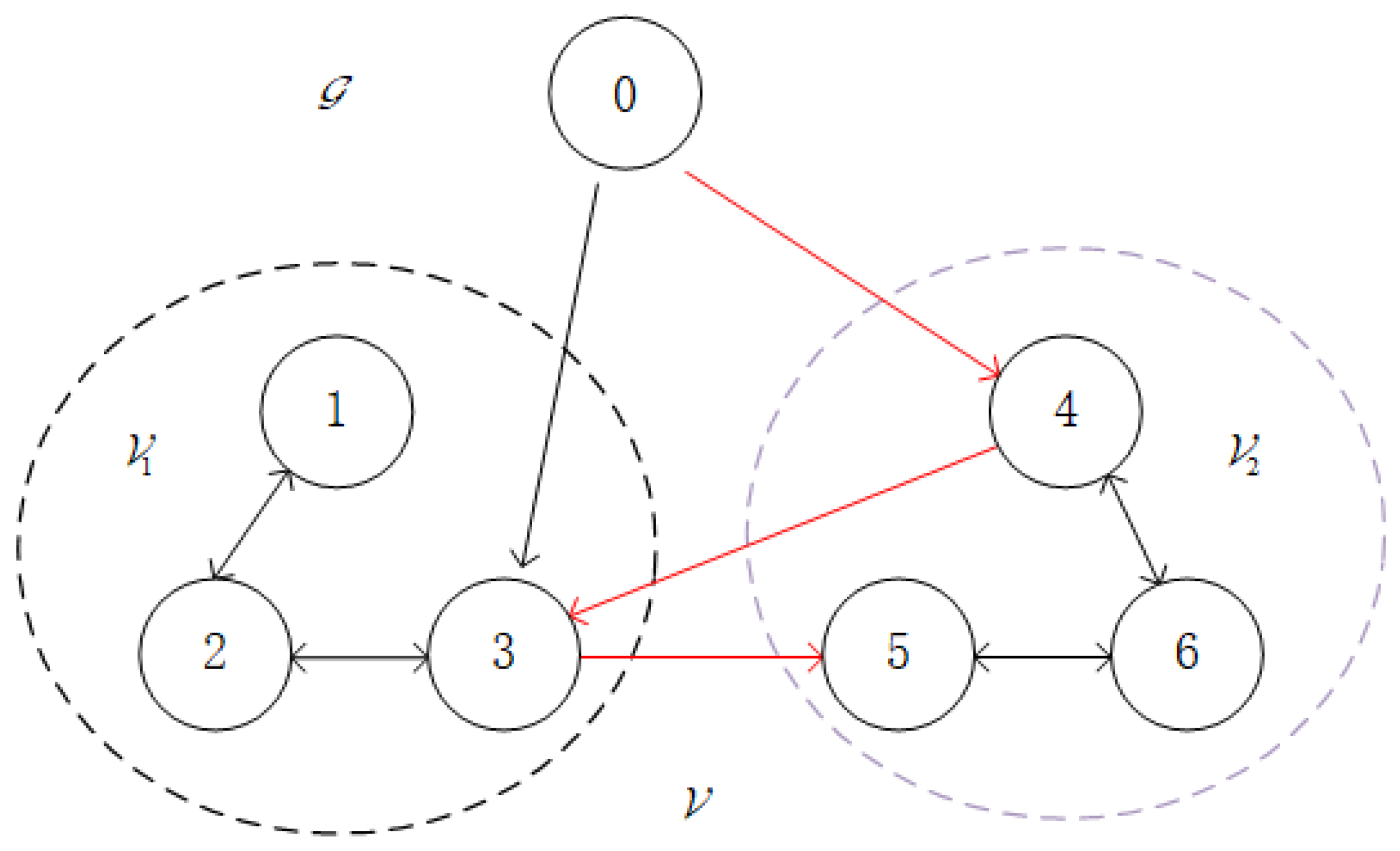
As illustrated in Figure 1, the BFMASs in the experiment are composed of one virtual leader and six followers, with a communication topology structure. The union of two sets is the directed graph’s vertex set, V = V 1 + V 2 , where V 1 = v p p = 1 , 2 , 3 and V 2 = v p p = 4 , 5 , 6 are the sets of vertices corresponding to the virtual leader and followers, respectively. The agents in set V 1 are assigned the formation control task with the desired trajectory y d , while the agents in set V 2 are assigned the formation control task with the desired trajectory y d . The Laplacian matrix of this BFMAS is given by:
L A = 1 1 0 0 0 0 1 2 1 0 0 0 0 1 2 1 0 0 0 0 0 1 0 1 0 0 1 0 2 1 0 0 0 1 1 2 ,
The matrix of relationships between the agents and the virtual leader is D = d i a g 0 , 0 , 1 , 1 , 0 , 0 .
Selecting the initial system output as
y ( k , 1 ) = [ y 1 ( k , 1 ) , y 2 ( k , 1 ) , y 3 ( k , 1 ) , y 4 ( k , 1 ) , y 5 ( k , 1 ) , y 6 ( k , 1 ) ] = 0.3 0.4 0.4 0.15 0.6 0.1 0.4 0.5 0.3 0.1 0.2 0.3 ,
Selecting the initial system input as u p k , 1 = 0 0 T and the related parameters ρ p = 0.32 , λ p = 0.41 , η p = 1 , μ p = 5 . The initial PJM is as Φ p ( k , 1 ) = 0.7 0.15 0.15 0.68 .

5.1.1. Simulation Experiment of BFMASs Under DoS Attacks

In order to confirm the effectiveness of the proposed scheme for BFMASs control under DoS attacks, simulation experiments are conducted using the traditional MFAILC scheme and the proposed DET-MFAILC scheme.
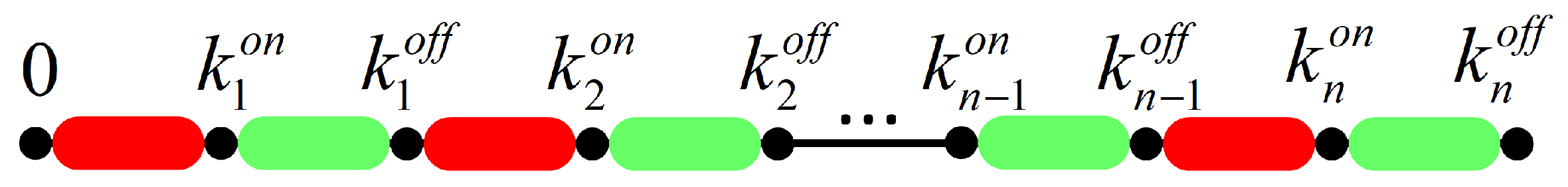
Figure 3 illustrates the periodic DoS attacks on the multi-agent system. The gray areas represent the active periods of the periodic DoS attacks, while the remaining areas represent the dormant periods. During the dormant periods of DoS attacks, the data transmission success rate between agents is set to 0.9, while during the active periods, the success rate is reduced to 0.7.
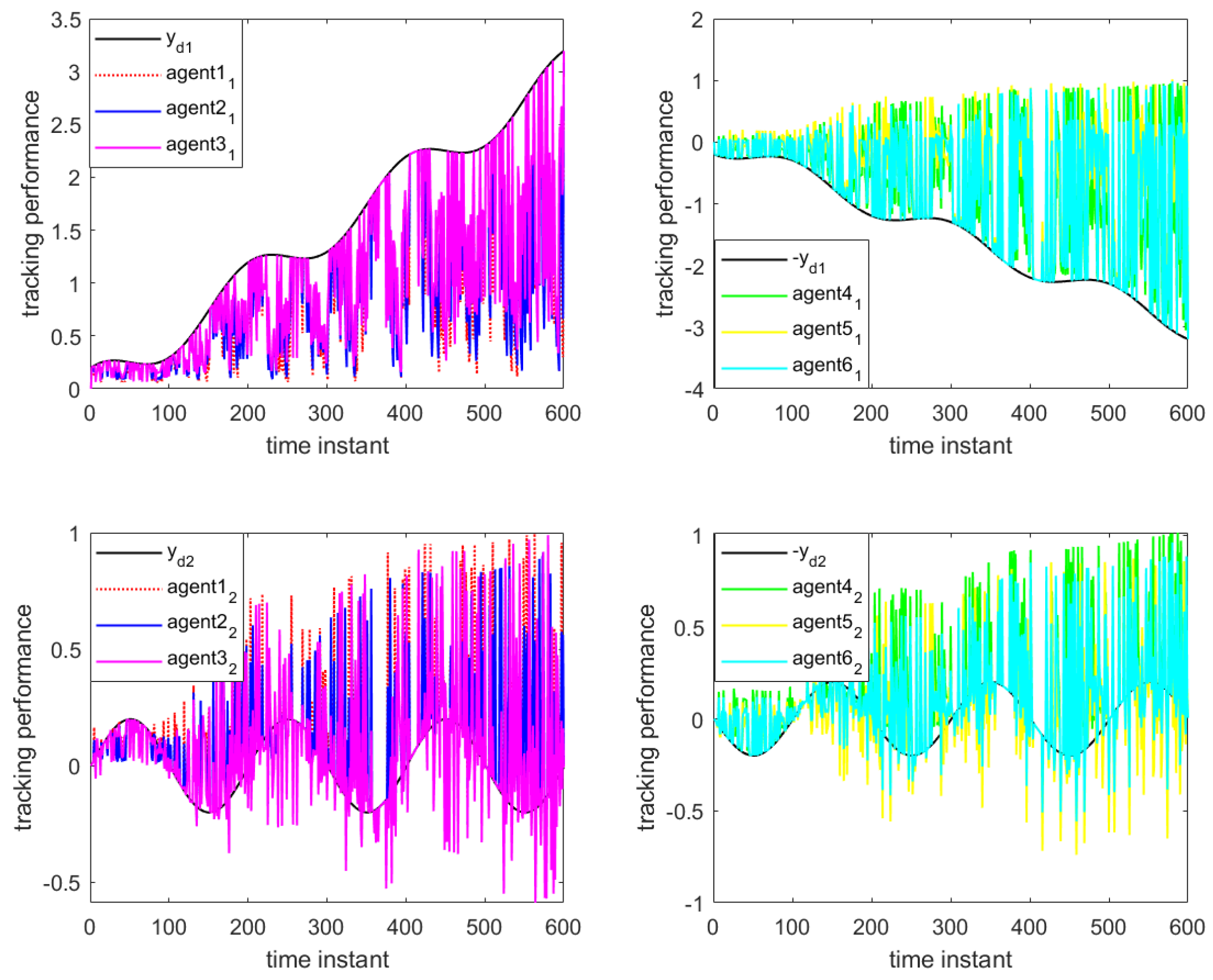
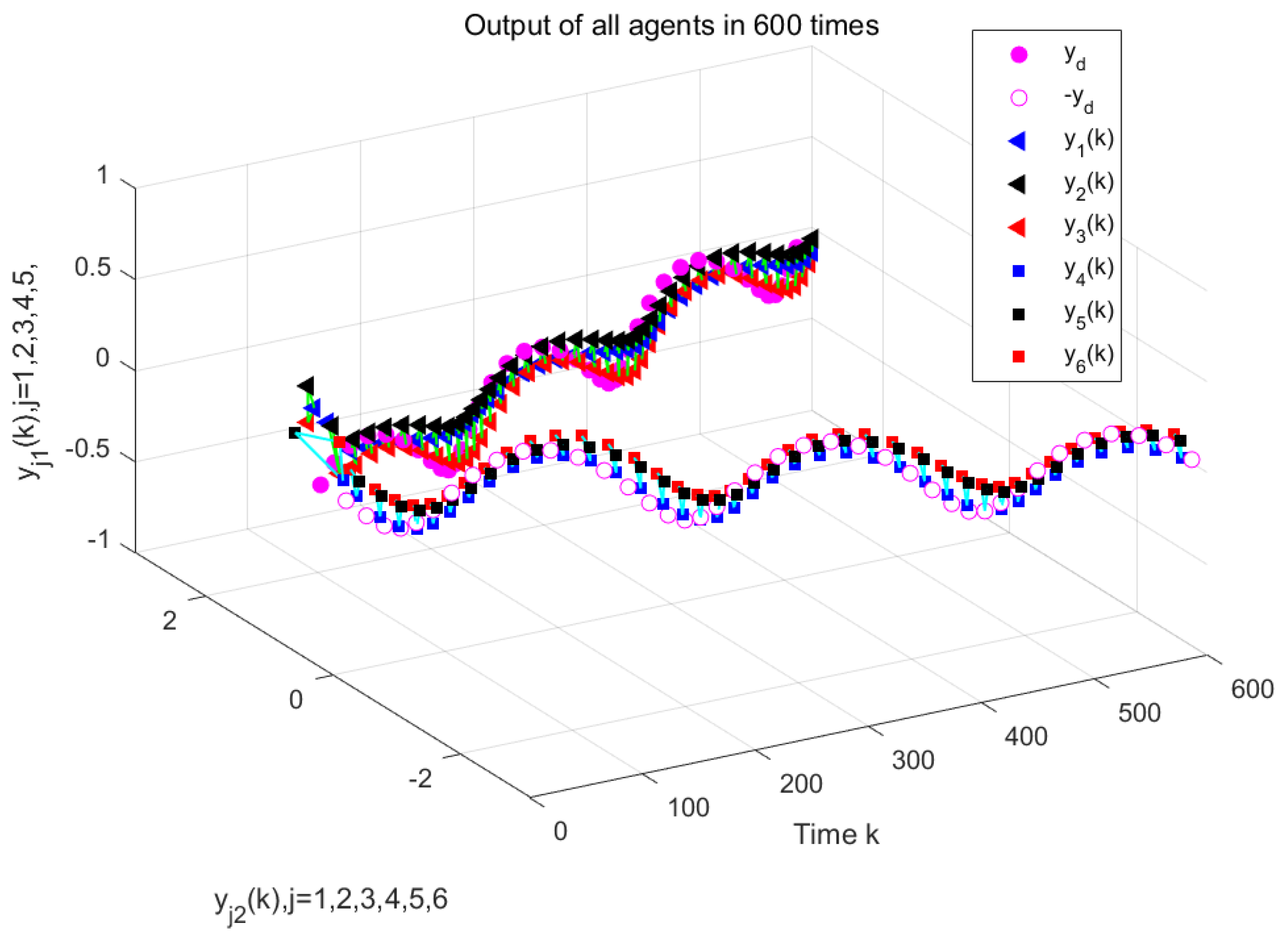
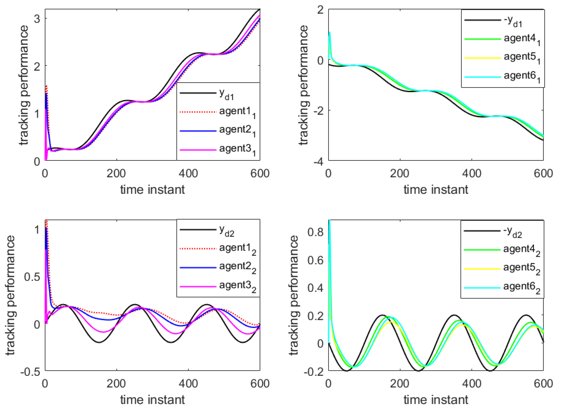
Figure 4 and 
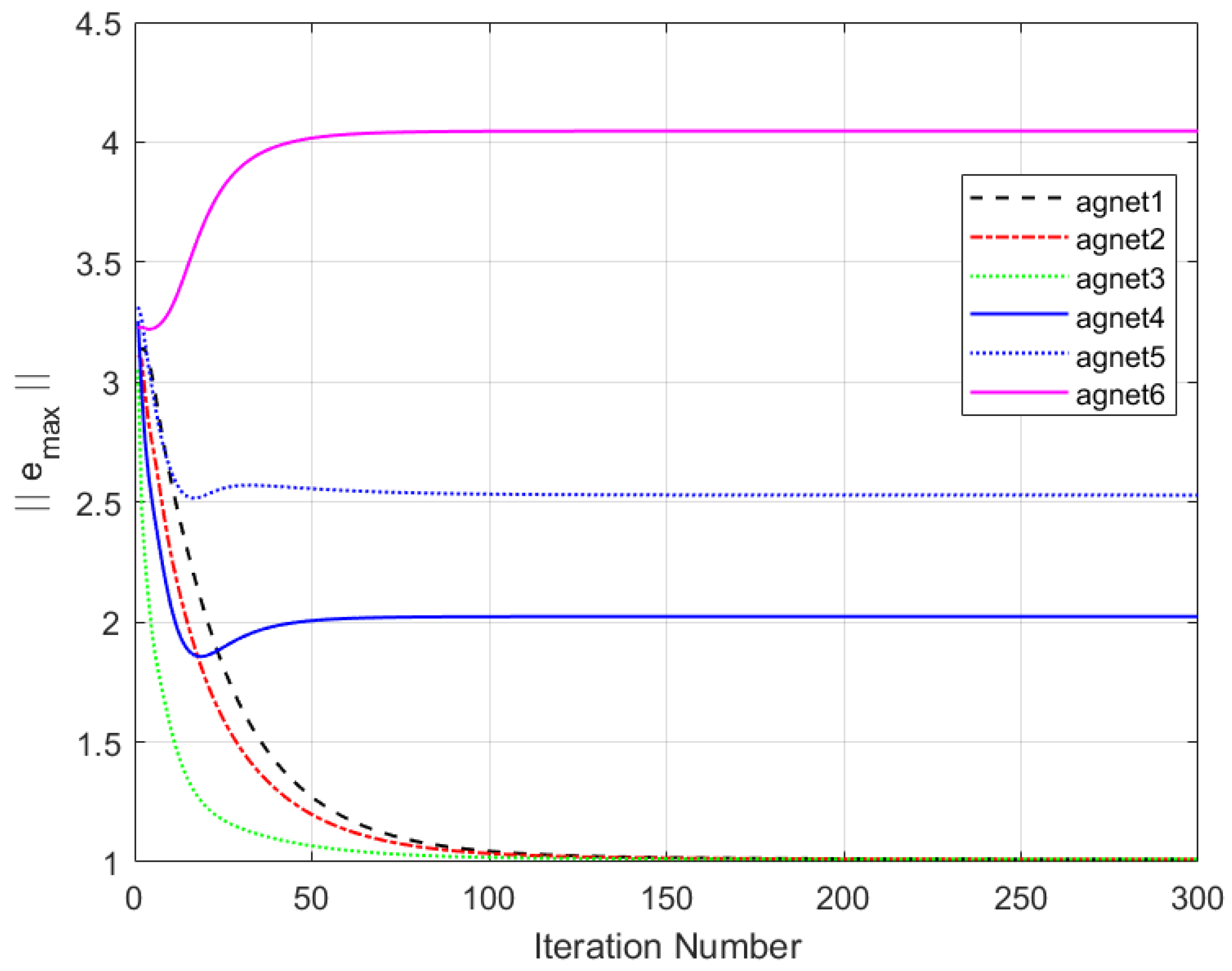
Figure 5 show the output results of the multi-agent formation at the 250th iteration and the output curves of each agent along the iteration axis, respectively, under periodic DoS attacks using the traditional MFAILC scheme. It is evident that due to the impact of DoS attacks, the agents do not track the trajectory of the virtual leader. The maximum tracking error of each agent along the iteration axis is shown in Figure 6. It can be observed that the maximum tracking error of each agent cannot converge to an ideal range.
Figure 7 and Figure 8 depict the output of the system under the MFAC algorithm with the same parameter conditions.
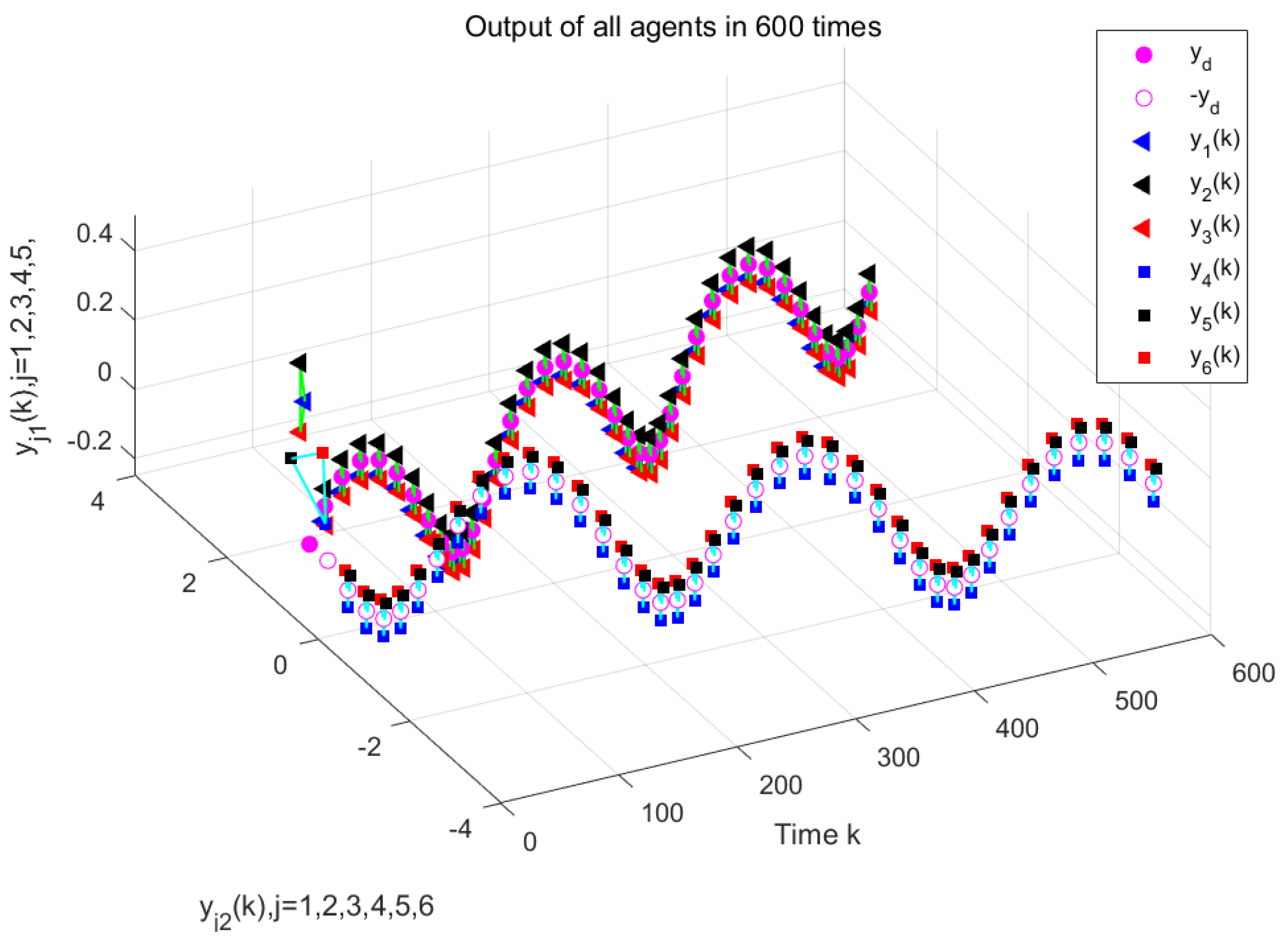
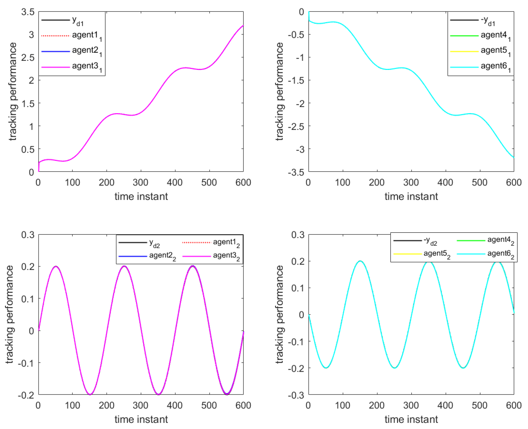
 Figure 9 and 
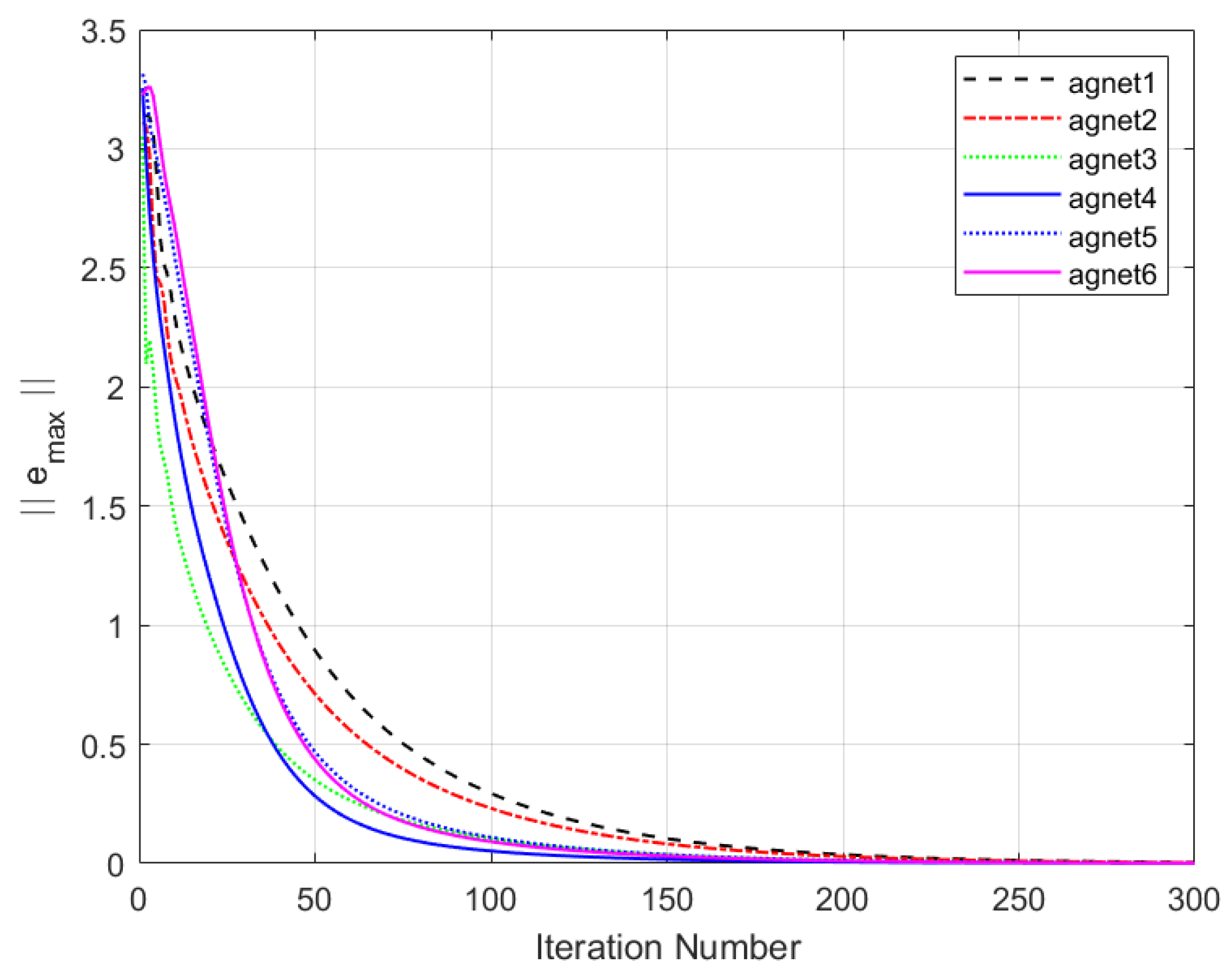
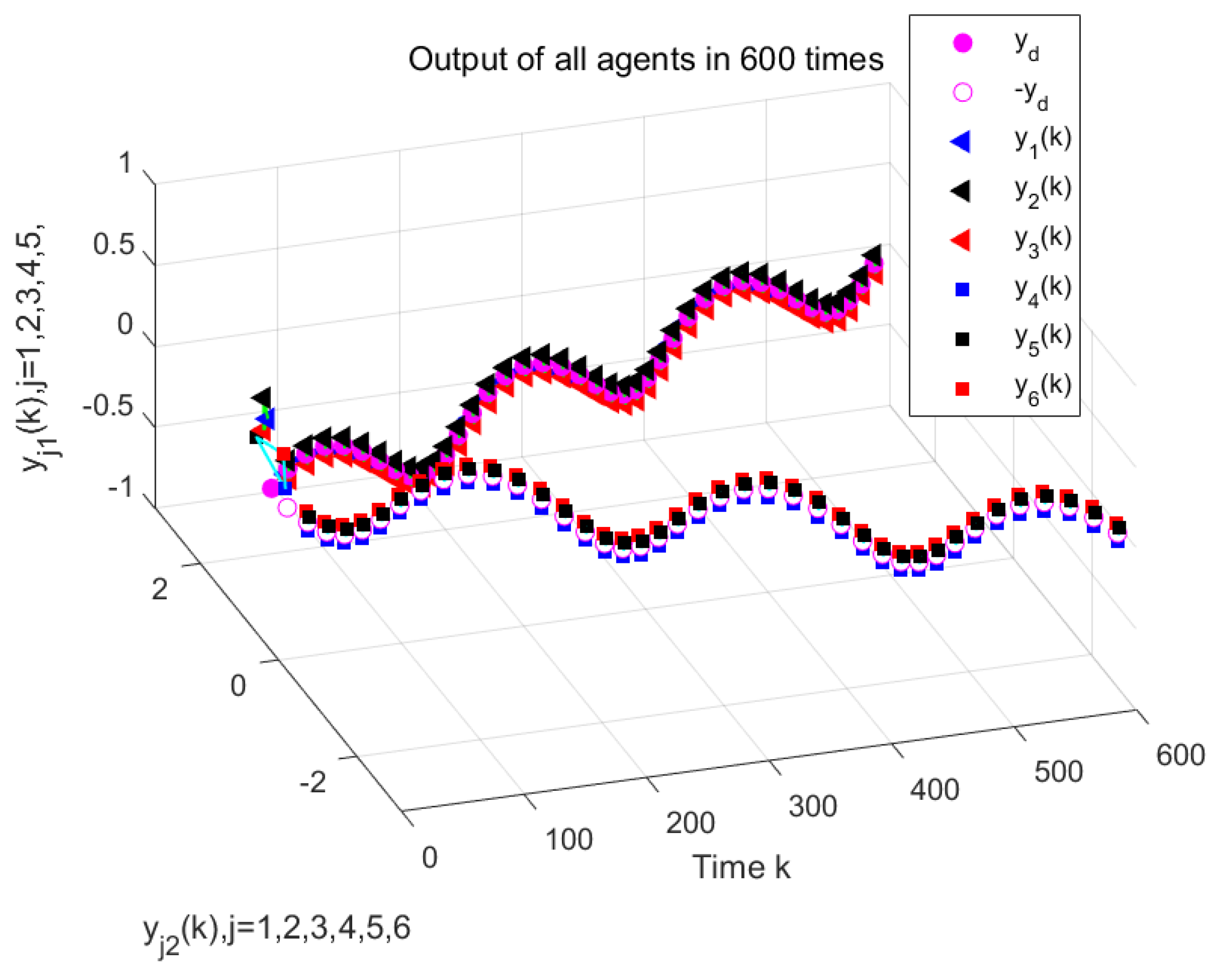
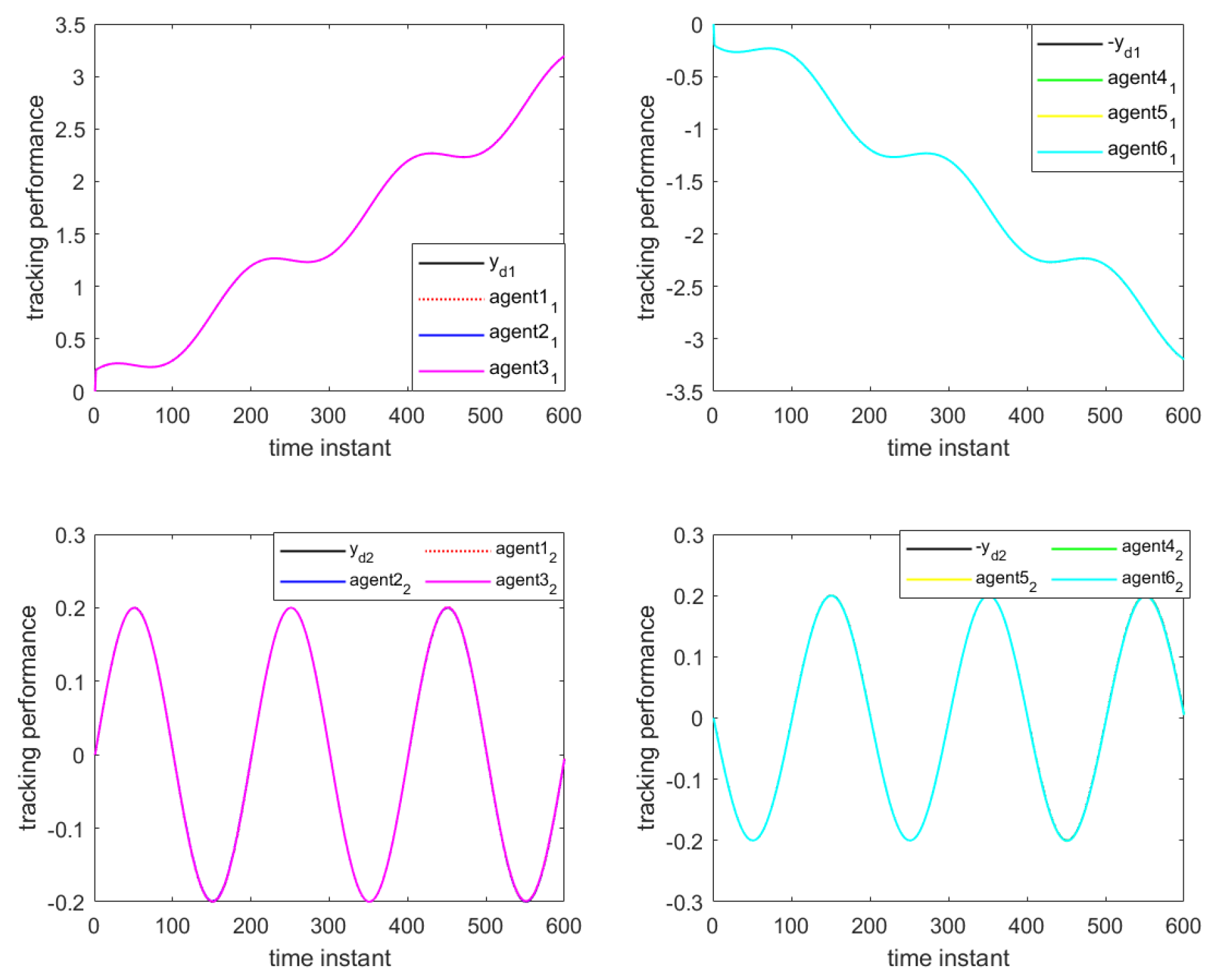
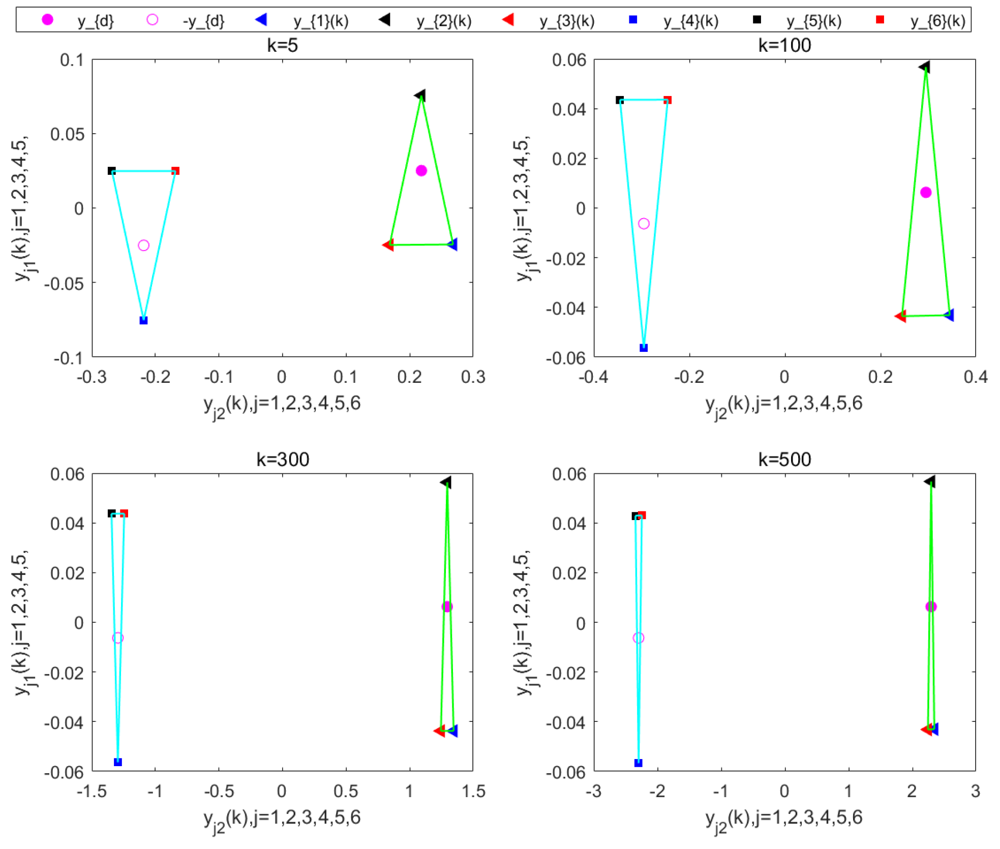
Figure 10 illustrate the formation control results at the 280th iteration and the output curves of each agent, respectively, using the proposed DET-MFAILC scheme with the DoS attack compensation mechanism under DoS attacks. It can be observed that the agents in the bipartite formation system effectively track the trajectory of the virtual leader. Figure 11 shows the maximum tracking error curves of the agents in this experiment. Despite the impact of DoS attacks, the maximum tracking errors of all agents converge stably and approach zero after 280 iterations. It can be seen that the tracking performance of the MFAC algorithm without the effect of DoS attacks is also significantly weaker than that of this paper. Figure 12 shows the variation in the mean squared error of ξ a p with the number of iterations, showing that it gradually decreases with the number of iterations.

5.1.2. Simulation Experiment of BFMASs Under Different Event-Triggered Condition

Comparing with [22], this paper incorporates both the consensus error and tracking error into the DET condition, resulting in a new DET condition, as shown in Equation (9). To verify its effectiveness, simulation experiments are conducted within the DET-MFAILC scheme using the DET condition proposed in [22] and the improved event-triggered condition proposed in this paper. The experimental results are shown in Figure 13 and Figure 14, respectively.
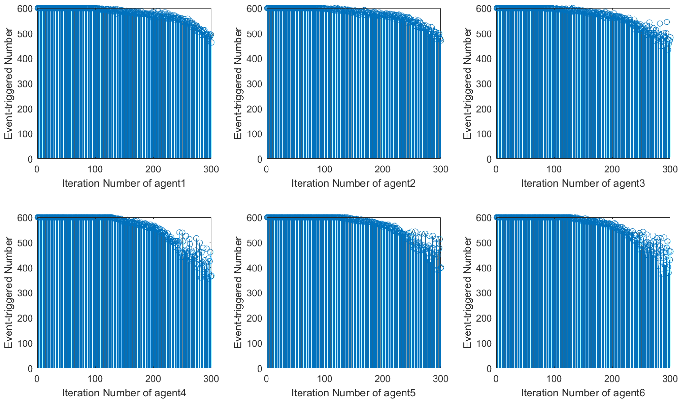
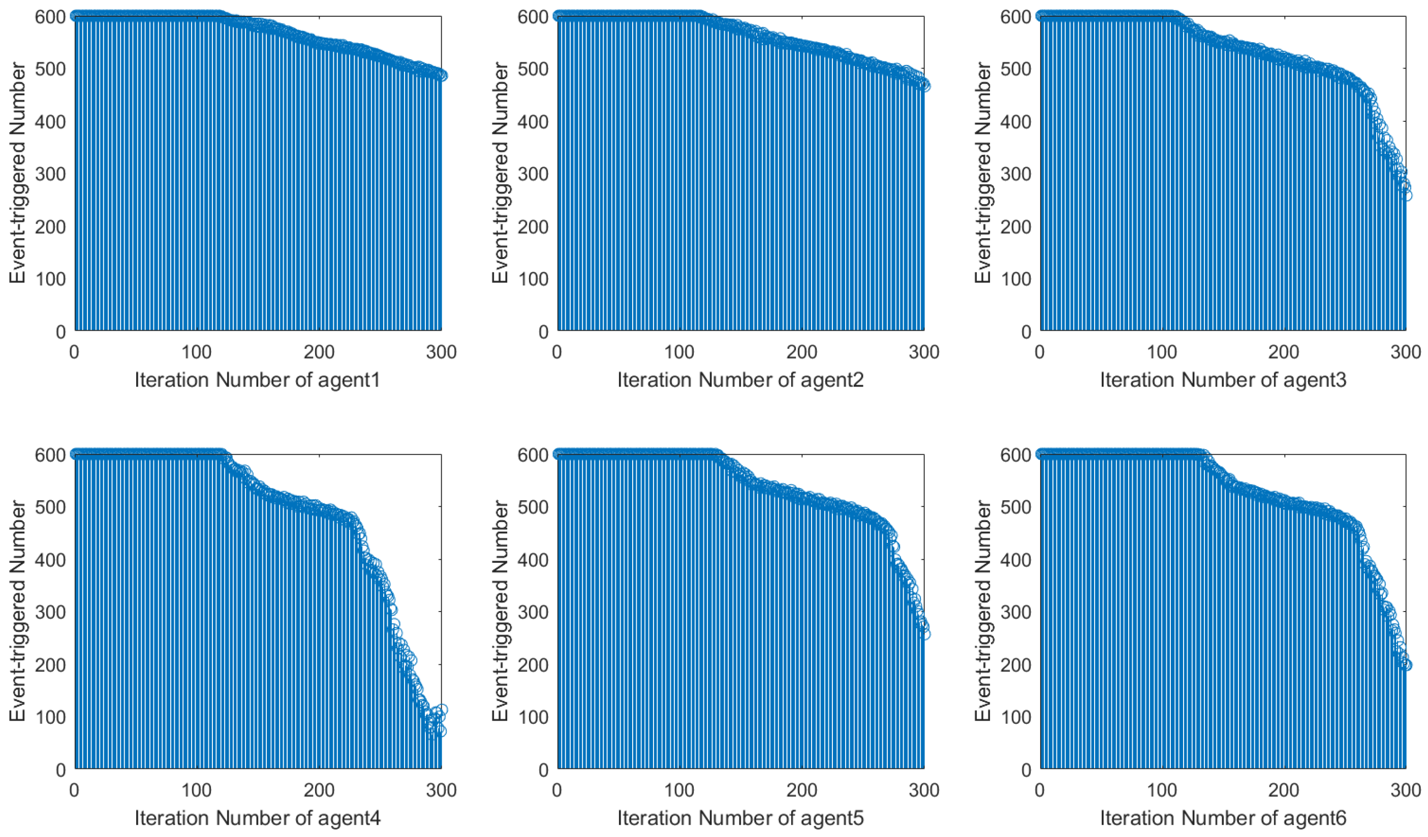
Using the DET condition from [22], it is evident that the number of event triggers during system operation decreases along the iteration axis but exhibits instability with fluctuations. In contrast, when using the DET condition proposed in this paper, the number of event triggers during system operation stabilizes and decreases significantly after 120 iterations. This shows how the event-triggered condition designed in this paper can more efficiently save network resources by reducing the amount of controller updates.

5.2. Extension to Time-Vraying Topology

This experiment verifies the effectiveness of the proposed DET-MFAILC scheme for controlling the formation of BFMASs with time-varying topologies. In the experiment, all initialization parameters are the same as those for the BFMASs with a fixed topology. The difference lies in that the communication topology of the BFMASs in this experiment is time-varying, as shown in Figure 15. The pattern of variation in the communication topology is as follows:
G ¯ 1 , 0 k 200 G ¯ 2 , 200 k 400 G ¯ 3 , 400 k 600
The simulation results are shown in Figure 16, Figure 17 and Figure 18. As can be seen in Figure 16 and Figure 17, all agents are able to effectively track the leader’s trajectory with good consensus. The tracking errors of the agents converge close to zero after 250 iterations, as shown in Figure 18. Furthermore, the formation shape of the agents is well maintained, as illustrated in Figure 19. These results verify that the proposed DET-MFAILC scheme also achieves good control performance in the bipartite formation control task of BFMASs with time-varying switching topologies.

6. Conclusions

Unlike most studies that focus on MASs composed of SISO-type single agents, this paper investigates bipartite formation trajectory tracking control MASs composed of MIMO-type single agents, considering the impact of periodic DoS attacks. To mitigate the effects of DoS attacks on bipartite formation systems, a DoS attack compensation mechanism is introduced. To reduce the frequency of controller updates, conserve network resources, and alleviate computational pressure while further enhancing the system’s ability to resist DoS attacks, an event-triggered condition is designed to construct a DET mechanism. The DoS attack compensation algorithm and DET mechanism are combined with the MFAILC method for controller design. Furthermore, this algorithm is extended from fixed topology systems to time-varying topology systems, and the convergence of the system is proven.
The simulation results show that for MIMO-type bipartite formation systems under periodic DoS attacks, the proposed algorithm ensures that the tracking errors and consensus errors of the agents converge to an ideal range close to zero and the formation shape is well maintained. The algorithm effectively suppresses the impact of DoS attacks on the formation system and reduces the frequency of controller updates, thus conserving network resources. Future research will focus on further integrating predictive control to achieve faster system convergence.

Author Contributions

Conceptualization, H.L.; methodology, H.L. and L.F.; software, H.L. and W.W.; validation, H.L., L.F. and W.W.; formal analysis, H.L.; investigation, H.L.; resources, L.F.; data curation, H.L.; writing—original draft preparation, H.L.; writing—review and editing, H.L. and L.F.; visualization, H.L.; supervision, L.F. and W.W.; project administration, L.F.; funding acquisition, L.F. All authors have read and agreed to the published version of the manuscript.

Funding

This work was supported by the National Natural Science Foundation of China (No. 62263017).

Institutional Review Board Statement

Not applicable.

Informed Consent Statement

Not applicable.

Data Availability Statement

All of the data generated and analyzed during this work are included in this paper.

Conflicts of Interest

The authors declare no conflict of interest.

References

  1. Briñón-Arranz, L.; Seuret, A.; Pascoal, A. Circular formation control for cooperative target tracking with limited information. J. Frankl. Inst. 2019, 356, 1771–1788. [Google Scholar] [CrossRef]
  2. Shao, S.; Zhao, Y.; Wu, X. Robust fixed-time formation control for quadrotor unmanned aerial vehicles with directed topology. TRansactions Inst. Meas. Control 2022, 44, 324–338. [Google Scholar] [CrossRef]
  3. Hu, J.; Niu, H.; Carrasco, J.; Lennox, B.; Arvin, F. Fault-tolerant cooperative navigation of networked UAV swarms for forest fire monitoring. Aerosp. Sci. Technol. 2022, 123, 107494. [Google Scholar] [CrossRef]
  4. Yu, Y.; Guo, J.; Chadli, M.; Xiang, Z. Distributed adaptive fuzzy formation control of uncertain multiple unmanned aerial vehicles with actuator faults and switching topologies. IEEE Trans. Fuzzy Syst. 2022, 31, 919–929. [Google Scholar] [CrossRef]
  5. Suryendu, C.; Subudhi, B. Formation control of multiple autonomous underwater vehicles under communication delays. IEEE Trans. Circuits Syst. II Express Briefs 2020, 67, 3182–3186. [Google Scholar] [CrossRef]
  6. Yan, B.; Shi, P.; Lim, C.C.; Shi, Z. Optimal robust formation control for heterogeneous multi-agent systems based on reinforcement learning. Int. J. Robust Nonlinear Control 2022, 32, 2683–2704. [Google Scholar] [CrossRef]
  7. Zhao, H.; Shan, J.; Peng, L.; Yu, H. Data-driven event-triggered formation of mimo multiagent systems with constrained information. IEEE Trans. Syst. Man Cybern. Syst. 2023, 54, 39–49. [Google Scholar] [CrossRef]
  8. Bu, X.; Hou, Z.; Zhang, H. Data-driven multiagent systems consensus tracking using model free adaptive control. IEEE Trans. Neural Netw. Learn. Syst. 2017, 29, 1514–1524. [Google Scholar] [CrossRef] [PubMed]
  9. Liang, J.; Bu, X.; Cui, L.; Hou, Z. Data-driven bipartite formation for a class of nonlinear MIMO multiagent systems. IEEE Trans. Neural Netw. Learn. Syst. 2021, 34, 3161–3173. [Google Scholar] [CrossRef]
  10. Bu, X.; Yu, Q.; Hou, Z.; Qian, W. Model free adaptive iterative learning consensus tracking control for a class of nonlinear multiagent systems. IEEE Trans. Syst. Man Cybern. Syst. 2017, 49, 677–686. [Google Scholar] [CrossRef]
  11. Ren, Y.; Hou, Z. Robust model-free adaptive iterative learning formation for unknown heterogeneous non-linear multi-agent systems. IET Control Theory Appl. 2020, 14, 654–663. [Google Scholar] [CrossRef]
  12. Bu, X.; Cui, L.; Hou, Z.; Qian, W. Formation control for a class of nonlinear multiagent systems using model-free adaptive iterative learning. Int. J. Robust Nonlinear Control 2018, 28, 1402–1412. [Google Scholar] [CrossRef]
  13. Zhao, H.; Yu, H.; Peng, L. Event-triggered distributed data-driven iterative learning bipartite formation control for unknown nonlinear multiagent systems. IEEE Trans. Neural Netw. Learn. Syst. 2022, 35, 417–427. [Google Scholar] [CrossRef] [PubMed]
  14. Liang, J.; Bu, X.; Hou, Z. Finite-time Asymmetric Bipartite Consensus for Multi-Agent Systems Using Data-Driven Iterative Learning Control. IEEE Trans. Signal Inf. Process. Over Netw. 2024, 10, 227–238. [Google Scholar] [CrossRef]
  15. Li, F.; Hou, Z. Distributed model-free adaptive control for MIMO nonlinear multiagent systems under deception attacks. IEEE Trans. Syst. Man Cybern. Syst. 2022, 53, 2281–2291. [Google Scholar] [CrossRef]
  16. Bu, X.; Yu, W.; Yin, Y.; Hou, Z. Event-triggered data-driven control for nonlinear systems under frequency-duration-constrained DoS attacks. IEEE Trans. Inf. Forensics Secur. 2022, 18, 1449–1460. [Google Scholar] [CrossRef]
  17. Liu, L.; Ma, L.; Wang, Y.; Zhang, J.; Bo, Y. Distributed set-membership filtering for time-varying systems under constrained measurements and replay attacks. J. Frankl. Inst. 2020, 357, 4983–5003. [Google Scholar] [CrossRef]
  18. Ding, L.; Han, Q.L.; Ge, X.; Zhang, X.M. An overview of recent advances in event-triggered consensus of multiagent systems. IEEE Trans. Cybern. 2017, 48, 1110–1123. [Google Scholar] [CrossRef] [PubMed]
  19. Wang, J.; Gao, J.; Wu, P. Attack-resilient event-triggered formation control of multi-agent systems under periodic DoS attacks using complex Laplacian. ISA Trans. 2022, 128, 10–16. [Google Scholar] [CrossRef]
  20. Deng, C.; Jin, X.Z.; Wu, Z.G.; Che, W.W. Data-driven-based cooperative resilient learning method for nonlinear MASs under DoS attacks. IEEE Trans. Neural Netw. Learn. Syst. 2023, 35, 12107–12116. [Google Scholar] [CrossRef] [PubMed]
  21. Qi, Y.; Zhao, X.; Ahn, C.K. Dual-Domain triggered iterative learning control for networked switched systems against denial-of-service attacks. IEEE Syst. J. 2022, 17, 3246–3257. [Google Scholar] [CrossRef]
  22. Zhao, H.; Xu, D.; Zhou, Z.; Yu, H. Dynamic Event-Triggered Resilient Heading Control for Unmanned Surface Vehicle With Encrypted Data. IEEE Trans. Intell. Veh. 2024; early access. [Google Scholar] [CrossRef]
  23. Zhao, H.; Peng, L.; Yu, H. Model-free adaptive consensus tracking control for unknown nonlinear multi-agent systems with sensor saturation. Int. J. Robust Nonlinear Control 2021, 31, 6473–6491. [Google Scholar] [CrossRef]
  24. Feng, J.; Song, W.; Zhang, H.; Wang, W. Data-driven robust iterative learning consensus tracking control for MIMO multiagent systems under fixed and iteration-switching topologies. IEEE Trans. Syst. Man Cybern. Syst. 2020, 52, 1331–1344. [Google Scholar] [CrossRef]
Figure 1. Communication topology of the agents.
Applsci 15 01921 g001
Figure 2. Schematic diagram of DoS attack working cycle.
Applsci 15 01921 g002
Figure 3. Diagram of periodic DoS attacks.
Applsci 15 01921 g003
Figure 4. System output of MFAILC under DoS attack (300th iteration).
Applsci 15 01921 g004
Figure 5. Tracking performance curves of MAFILC under DoS attack (300th iteration).
Applsci 15 01921 g005
Figure 6. Maximum tracking error of MAFILC under DoS attack.
Applsci 15 01921 g006
Figure 7. MAFC system output.
Applsci 15 01921 g007
Figure 8. Tracking performance curves of MFAC.
Applsci 15 01921 g008
Figure 9. DET-MAFILC system output with compensation mechanism under Dos attack (280th iteration).
Applsci 15 01921 g009
Figure 10. Tracking performance curves of DET-MAFILC with compensation mechanism under DoS attack (280th iteration).
Applsci 15 01921 g010
Figure 11. Maximum tracking error of agents under DoS attacks.
Applsci 15 01921 g011
Figure 12. The MSE of ξ a p .
Applsci 15 01921 g012
Figure 13. The ET signal of condition [22].
Applsci 15 01921 g013
Figure 14. The ET signal of this paper.
Applsci 15 01921 g014
Figure 15. Time-varying topology of BFMASs.
Applsci 15 01921 g015
Figure 16. DET-MAFILC system output with compensation mechanism under Dos attack (250th iteration).
Applsci 15 01921 g016
Figure 17. Tracking performance curves of DET-MAFILC with compensation mechanism under DoS attack (250th iteration).
Applsci 15 01921 g017
Figure 18. Maximum tracking error of agents under DoS attacks.
Applsci 15 01921 g018
Figure 19. Formation at different sampling times k (250th iteration).
Applsci 15 01921 g019
Disclaimer/Publisher’s Note: The statements, opinions and data contained in all publications are solely those of the individual author(s) and contributor(s) and not of MDPI and/or the editor(s). MDPI and/or the editor(s) disclaim responsibility for any injury to people or property resulting from any ideas, methods, instructions or products referred to in the content.

