3.1. Principal and Modeling of Electret Transducer Component
After polarization, the permanently polarized charges distributed on the surface of the electret serve as a source of electrostatic field, inducing surface charges on the metal plates. Relative motion causes changes in the equivalent capacitance of the electrostatic structure and the induced charge on the plates. This charge will be released into the external circuit, resulting in current output.
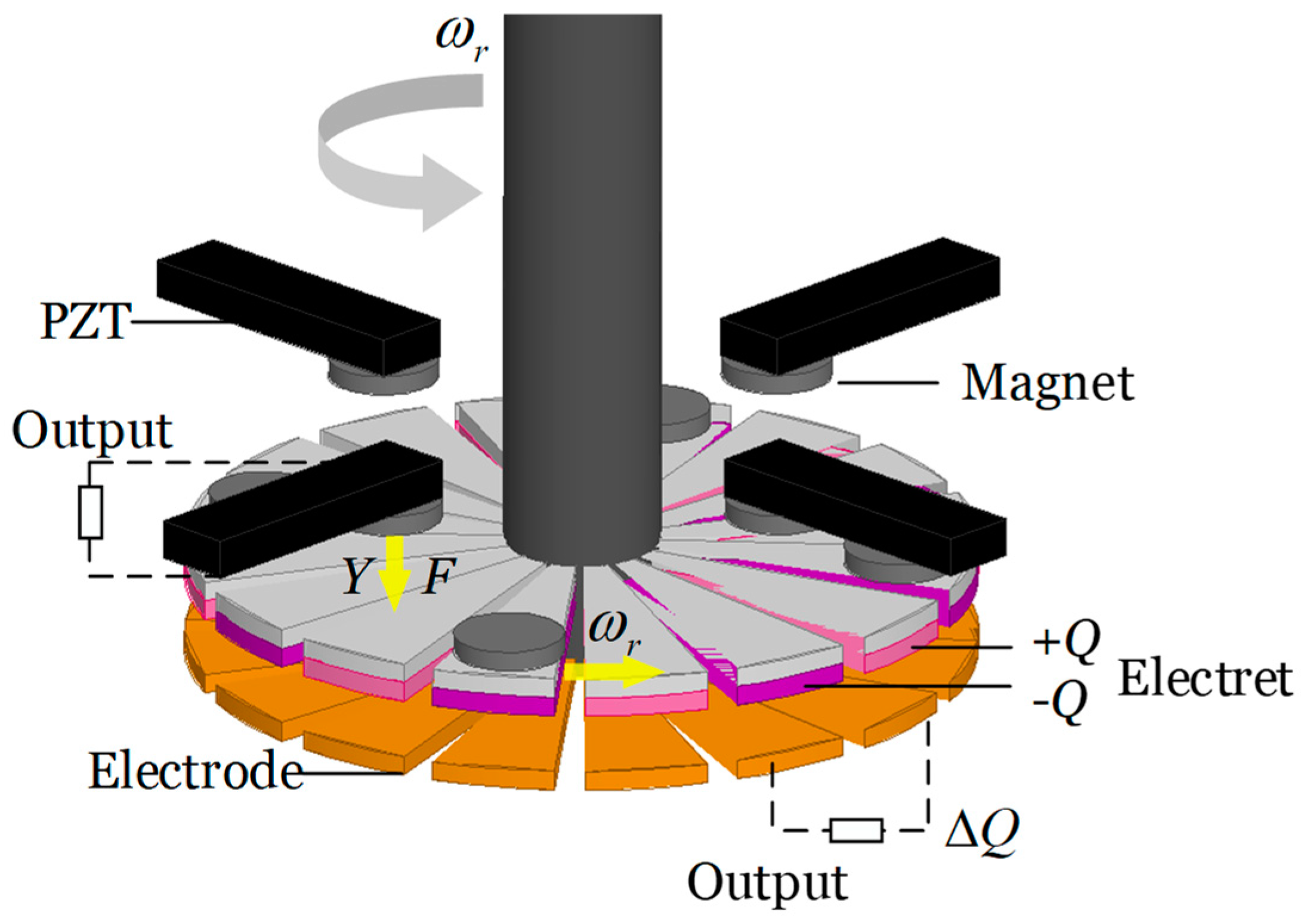
In this structure, the electret transducer component consists of 16 plates arranged in pairs, equivalent to eight pairs of electrodes in parallel, enhancing the absolute output magnitude of the component. Due to the highly symmetric structure, a single pair of plates is analyzed. The working principle of the electret electrostatic component is based on the phenomenon of electrostatic induction with the electret acting as the field source.
The ideal model can be derived from the charge induction and inter-electrode charge transfer theory of a parallel plate capacitor [
12]. The theoretical model is based on the near-field assumption, which posits that under the condition where the distance between the plates is very small relative to the area of the plates, the electric field strength within the gap between the plates is uniformly distributed and perpendicular to the surface of the metal plate electrode. Furthermore, this model could only consider the interaction between the plates and the portion of the electret directly opposite them, because of the hypothesis that both the electret and the air are linear and uniform dielectrics, with a constant dielectric constant and a uniformly distributed internal electric field in the direction perpendicular to the upper and lower surfaces. Let the surface potential and charge of the upper side of the unipolar electret film be 0, while the lower side carries uniform unipolar surface charge. The electric field on both sides of the electret surface is discontinuous. Furthermore, the electret achieves fixed charges through high-voltage polarization; thus, its polarization effect could be neglected in the conditions of this model. Then, the induced charge on the upper surface of the metal plates could be calculated. When a unipolar electret moves from above plate 2 to above plate 1, the principle of electrostatic induction is illustrated in
Figure 5 and then obtains Equation (2).
On a unipolar electret, the surface charge and electric potential on the upper surface are zero, while the charge density
on the lower surface is fixed. As the electret moves, varying induced charges are generated in the region directly opposite the electrode plates, forming electric fields
Er and
E1 within the electret and between the plates, as well as surface potentials
V1 and
V2. As the assumption mentioned earlier, neglecting the gap between electrodes and assuming a very small separation between the electret and the electrode plate, Equation (2) describes the electrostatic induction at the region of the electret directly opposite the plates:
where
d represents the distance between the electret and the plates,
h is the thickness of the electret,
and
are the dielectric constants of the electret and air, respectively,
S is the area of the electret directly opposite the plates, and
C represents its equivalent capacitance. The induced charge density
on plate 1 can be concluded as Equation (3):
The electret and the electrode have a sector angle of
. During one cycle of rotating based the hypothesis of the model, the total induced charge
Q1 on electrode 1 varies as Equation (4):
where
S represents the area of the sector-shaped plate directly opposite the electret, and
r is the radius of the sector. When the electret moves at a speed of
, the induced charge quantity varies, initially increasing and then decreasing, repeating this cyclical variation with the arrival of the next electret. It can be considered that the induced charge
Q2 on plate 2 follows a similar pattern but is
phase advance.
In this model, the movement of the electret will lead to changes in the induced charge on the plates. Since there is a pathway between the plates, the induced charge can result in changes through charge transfer in the circuit, thereby generating output current. The open-circuit voltage between the plates is determined by the charge difference between them, while the output short-circuit current is determined by the amount of charge transferred between the plates [
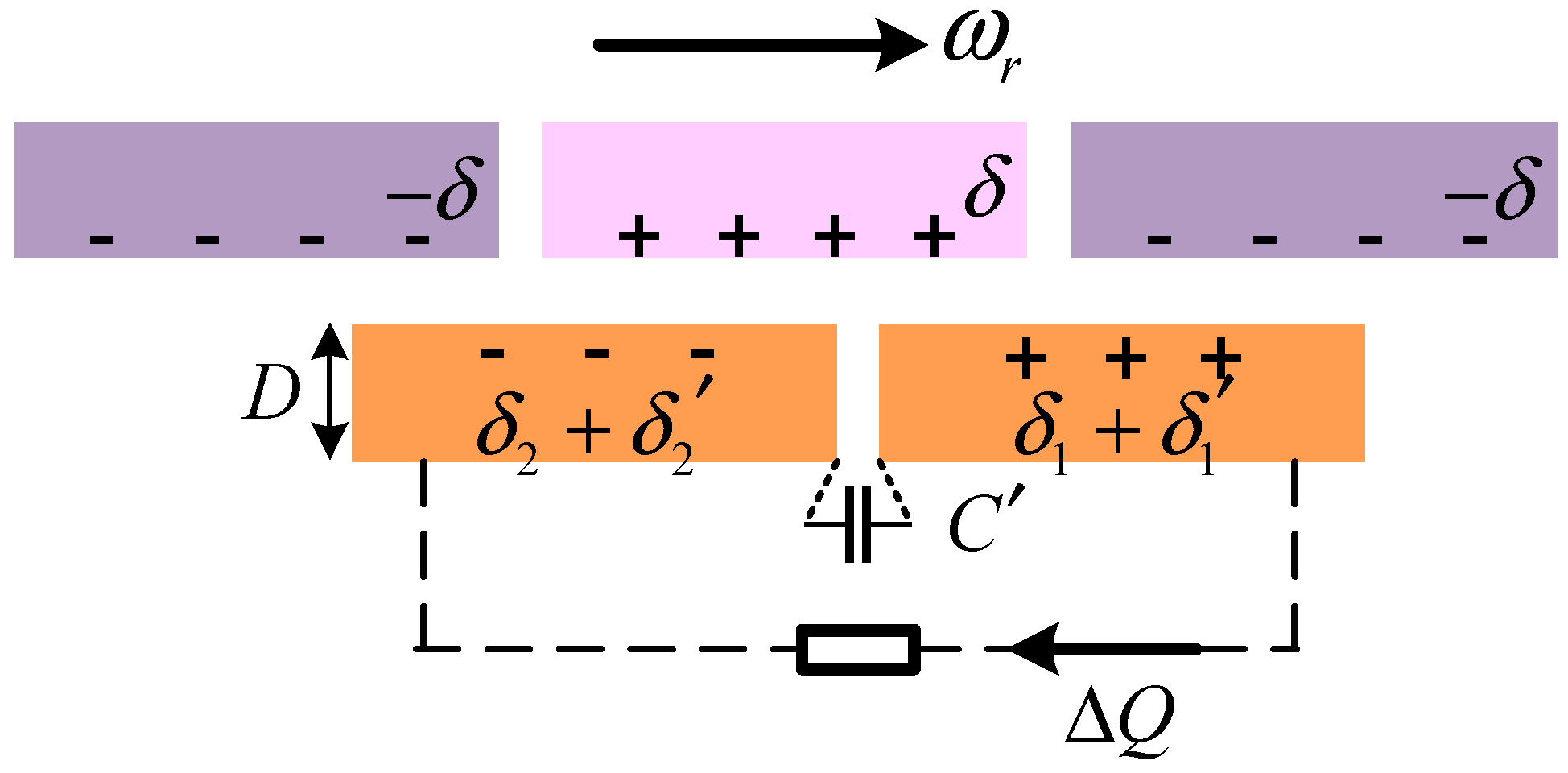
12]. Therefore, increasing the induced charge difference between the plates and its variation amplitude can enhance the output capability of the component. By using electrets with the same surface charge but opposite polarities arranged in intervals, the amplitude of the induced charge variation on plates that are close enough can be increased within one cycle, expanding the range of charge variation beyond a single polarity. When employing a unipolar electret with alternating positive and negative charges, the structural variation is illustrated in
Figure 6.
The induced charge on the electrode plate is simultaneously influenced by the electret with surface charge densities of
and
. Continuing to analyze the right electrode plate 1, the induced charge generated by the negatively polarized electret directly opposite the area of
is denoted as
. Then, Equation (4) could be modified as following Equation (5) for the optimized model, based on the same assumptions:
Similarly, Q2 leads by , half a cycle. If a structure with alternating positive and negative charges is not used, the number of unipolar electrets arranged at equal intervals must be less than the number of electrodes for the induced charge on the plates to vary.
The change in charge allows for current output between the two plates, where the short-circuit current
Isc and open-circuit voltage
Uoc of alternating positive–negative unipolar electret structure conform to the following Equations (6) and (7) in this model:
where
D represents the thickness of the electrode plate,
L is the length of the electrode plate, and
is the capacitance between the plates, which becomes a constant once the dimensions and arrangement of the plates are determined. The alternating positive–negative unipolar electret structure increases the amplitude of charge variation and the charge difference between paired plates, thereby enhancing the output performance of the electret transducer component.
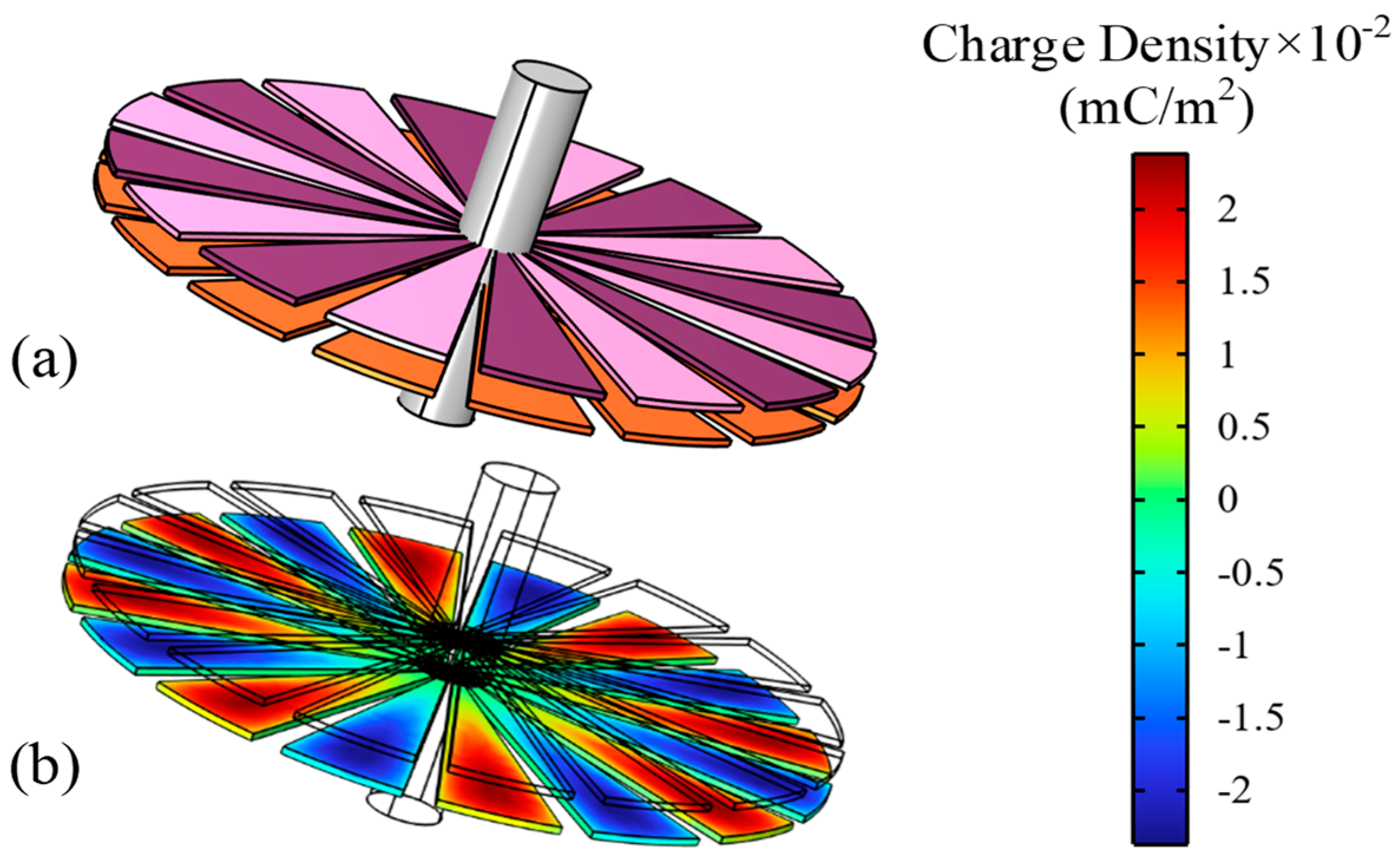
As the rotational speed increases, the amplitude of the short-circuit current theoretically grows linearly, while the amplitude of the open-circuit voltage remains unchanged. A finite element simulation of a steady-state electrostatic induction distribution model is constructed to calculate the output performance of the alternating positive and negative polarity electret-optimized transducer component, based on theoretical models and assumptions. Then, use the finite element simulation software COMSOL v.6.2 for modeling. Establish the boundary conditions by applying surface charge density of 0.05 mC/m
2 to the lower surface of the electret, while the charge and potential on the upper surface are set to zero. The surface charge distribution on the copper electrode plates is illustrated in
Figure 7.
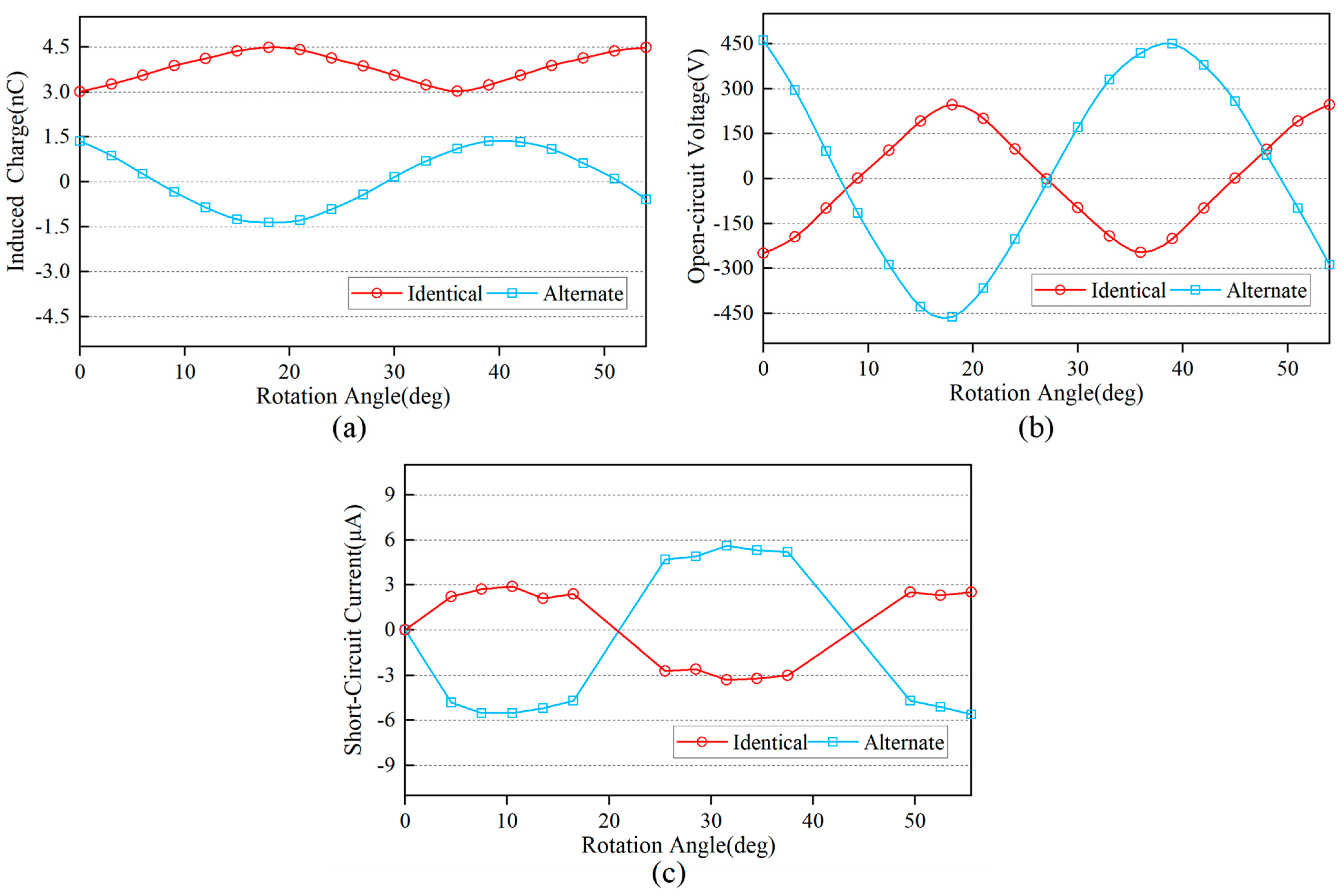
The equivalent capacitance of 2.976 pF between the paired plates is calculated via simulation. Rotating the electret layer changes the relative position between the copper electrode plates and the electret, resulting in the following variations in induced charge and open-circuit voltage for each pair of copper plates in
Figure 8.
The simulation results indicate that when the distance between the electrode and the electret is sufficiently small, the induced charge on the electrode surface is dominated by the nearest electret film. Although the interleaved polarities of the electret structure lead to certain degree of reduction in the absolute charge amount on the copper electrode plates due to the partial cancelation of the opposing electric fields, this configuration can significantly enhance the variation in the induced charge on the electrode and the charge difference between paired electrode. As a result, the open-circuit voltage and short-circuit current of the component are improved. With a rotational speed set at 60 rad/s, the short-circuit current output of the component during the rotation of the electret layer is derived from Equation (6). The simulation results align closely with theoretical expectations, and electret transducer component exhibits characteristics of high open-circuit voltage, low-output current, and high dynamic equivalent resistance. And all the simulation results converge successfully, achieving the tolerance requirement of 1 × 10⁻⁶after nine iterations.
Moreover, from Equations (6) and (7), it can be inferred that with fixed size parameters and structure, both the amplitude of the current and the frequency of voltage, as well as the current variations, are brief and positively correlated with rotational speed, unaffected by complex factors. Thereby, it presents potential for inversion analysis to derive rotational speed and wind speed information from the output signals of the paired plates.
3.2. Principal and Modeling of Piezoelectric Transducer Component
The output signal of piezoelectric transducers is often difficult to apply in signal inversion monitoring due to uncertainties such as excitation frequency and damping. However, it could compensate for the limitations of electrostatic transducers, which have lower power density. The excitation frequency does not necessarily equal the vibration response frequency, and the magnetically actuated piezoelectric transducer utilizes this characteristic to achieve frequency up-conversion, which is commonly used in low-frequency situations where the excitation frequency does not easily reach the resonance frequency. As researched in [
22,
23], the magnetically actuated structure can be simplified to state that when the permanent magnet approaches the cantilever beam, it provides a brief magnetic excitation based on magnetic force
F, causing the cantilever beam to undergo initial deformation and store maximum elastic potential energy. Once the magnet moves away, based on the principle of damped natural vibration, the excitation can be regarded as ceasing, and the cantilever beam will vibrate from the maximum amplitude, decaying exponentially at its natural frequency to stop, in the form of underdamped response, until the next magnetic excitation occurs. The motion process and output voltage have been confirmed to exhibit periodicity, while the natural frequency, which is also referred to as the first-order characteristic frequency, and the excitation frequency are the primary frequency components.
Compared to resonant systems that operate at their characteristic frequency, magnetically actuated systems operate over a much wider frequency range but with lower output. To increase the output power of the magnetically actuated piezoelectric component, in addition to the most basic way that increase the number of permanent magnets to trigger the oscillation decay process based on natural frequency more frequently, changing the structure and dimensions of the piezoelectric cantilever beam is also a method. Studies [
24,
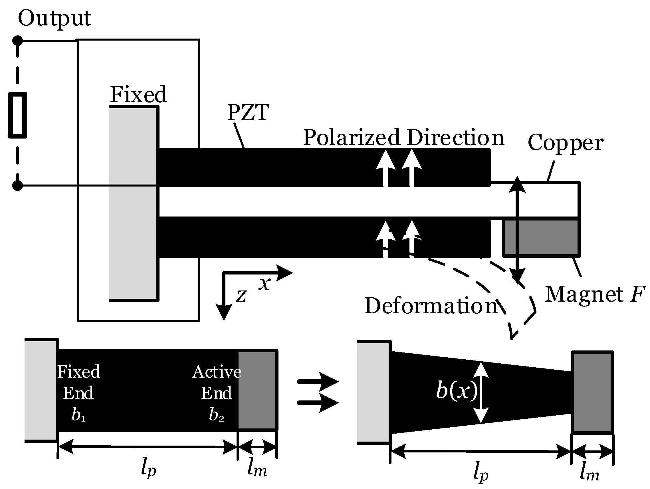
25] show that replacing the rectangular cantilever beam with a variable cross-section cantilever beam structure will cause changes in the natural frequency of the piezoelectric cantilever beam, the surface area of the piezoelectric layer, and the stress or charge distribution on surface, thereby affecting the output of the piezoelectric cantilever beam. Thus, increasing the output of the magnetically actuated piezoelectric component based on the optimization method of non-uniform cross-section cantilever beams is chosen. The coupled structure uses four sets of piezoelectric double-layer cantilever beams in parallel, with a single component structure used for calculation and analysis shown in
Figure 9.
When the polarization directions of the upper and lower piezoelectric layers are the same, the polarities are opposite during the bending deformation of the cantilever beam, and they are connected in parallel. Assuming that the piezoelectric cantilever beam model is composed of linearly elastic materials with uniform distribution, small deformations occur within the linear elastic range to avoid damaging the fragile piezoelectric layer. Under the linear elastic deformation model, stress and strain are proportional and exhibit a uniform distribution. When the rotation positions the permanent magnet directly below the active end of the piezoelectric cantilever at a certain moment, the magnetic force
F between the magnets is maximized at this point, which will cause the piezoelectric cantilever to undergo the greatest linear elastic deformation. Based on the above conditions, combining with the research in [
24], the strain distribution
SF(
x,
z) at the maximum linear elastic deformation of the length direction
x can be considered as Equation (8):
where
M(
x) represents the bending moment,
z is the coordinate in the thickness direction relative to the neutral plane,
I(
x) is the moment of inertia of the cross-section,
Y denotes the elastic modulus, and
lp and
lm are the lengths of the piezoelectric section and the excitation section, respectively.
is the system modulus, which is the equivalent elastic modulus of the entire cantilever beam calculated by combining the layer thicknesses and elastic moduli of the piezoelectric layer and the copper electrode layer, and is a constant when the material and thickness are determined.
b(
x) is the width of the beam at position
x. If the width of the fixed base is equal while the width of the movable base is relatively reduced,
b(
x) becomes smaller, which leads to an increase in strain at position
x. Conversely, increasing the width of the fixed base results in an increase in
b(
x) and a decrease in strain.
The variation in
b(
x) not only affects the strain but also alters the area of the piezoelectric layer. The working principle of the piezoelectric cantilever beam is based on surface charge generated during deformation of the piezoelectric material. In the simplified model of piezoelectric component, the upper and lower surfaces could be regarded as capacitor plates, while the open-circuit voltage arises from the charge difference between the surfaces [
12,
13,
24]. Deformation will alter the surface charge and also change the open-circuit voltage; the piezoelectric output of the capacitance-like simplified model can be jointly solved according to Equation (9):
where
D(
x, z) represents the distribution of the electric displacement vector on the surface of the piezoelectric layer,
d31 is the piezoelectric constant of the cantilever beam structure, and
is the elastic modulus of the composite material, which is dependent only on the materials and layer thickness.
Cp,
, and
zp denote the internal equivalent capacitance, dielectric constant, and thickness of the piezoelectric material, respectively. Due to the assumption of linear elastic small deformation, the strain on the upper and lower surfaces during the loading and deformation process has a negligible effect on the capacitance surface area and spacing, which could be considered constant.
Qp and
Up are the total surface charge and open-circuit voltage characterizing the output performance of the piezoelectric layer, respectively. Since the discussion is based on a linear elastic deformation model, it can be deduced from the principle of symmetry that the strains on the upper and lower surfaces of the same material section of the cantilever beam are equal in magnitude but opposite in direction, resulting in equal magnitude but opposite charges on the upper and lower surfaces of the piezoelectric layer. Organize Equations (8) and (9) to obtain the expression Equation (10) for
Qp and
Up of the model:
where
b1 and
b2 refer to the fixed end and the active end widths shown in
Figure 9, respectively. It can be concluded that, in this model, changing either
b1 or
b2 to gain the non-uniform cross-section piezoelectric cantilever beam will alter the strain distribution and the open-circuit voltage of the component while keeping the same applied force, but it will not affect the total surface charge.
When the rotation moves the permanent magnet away from the piezoelectric cantilever beam, it can be considered that the applied force disappears, and the cantilever beam vibrates with exponentially decaying amplitude at its natural frequency
to stop. Studies [
22,
23] have shown that the output voltage of the magnetically actuated structure vary with the vibrational deformation of the cantilever beam, exhibiting the same exponential oscillatory decay based on the natural frequency
, in the form of underdamped response. Therefore, the output voltage can be defined as
, where
Up represents amplitude, and
is the oscillatory function that characterizes the exponential oscillatory decay of the voltage based on the natural frequency as in Equation (11) under ideal conditions:
where
represents the initial phase, and
is the damping ratio. For the simplified model of linear elastic small deformation, the piezoelectric cantilever beam was expected to respond well under magnetically actuated excitation without excessive damping; this model is designed and analyzed with light damping ratio
of 0.045. Since it has been mentioned earlier that the internal equivalent capacitance
Cp is regarded constant during the vibrational deformation process, it can be inferred that the total surface charge
Qp will also follow the same pattern as the output voltage during vibration, which can be defined as
. And the output current of the piezoelectric component is derived from the change in surface charge that flows through the circuit, with no current output in the static state. During the vibration process, the output current could be represented by
or
ideally in this simplified piezoelectric model, which is as a capacitance-like structure. Therefore, increasing the natural frequency
could increase the charge’s rate of change and then enhance the output current amplitude of the piezoelectric component within one cycle. Based on research in [
24,
25], a cantilever beam with a non-uniform cross-section has been approved, and it was found that increasing the width of the fixed end will enhance its bending stiffness and elevating the characteristic frequency. Conversely, reducing the width of the movable end decreases the stiffness and characteristic frequency. Thus, the method of achieving non-uniform cross-section piezoelectric cantilever beams by varying
b1 or
b2 can change the output voltage, and the output current also could be enhanced by the increase in natural frequency through this method. Based on this, the design of the piezoelectric cantilever beam’s size and structure can be optimized to improve the output voltage or output current, thereby increasing the output power of the magnetically actuated piezoelectric component.
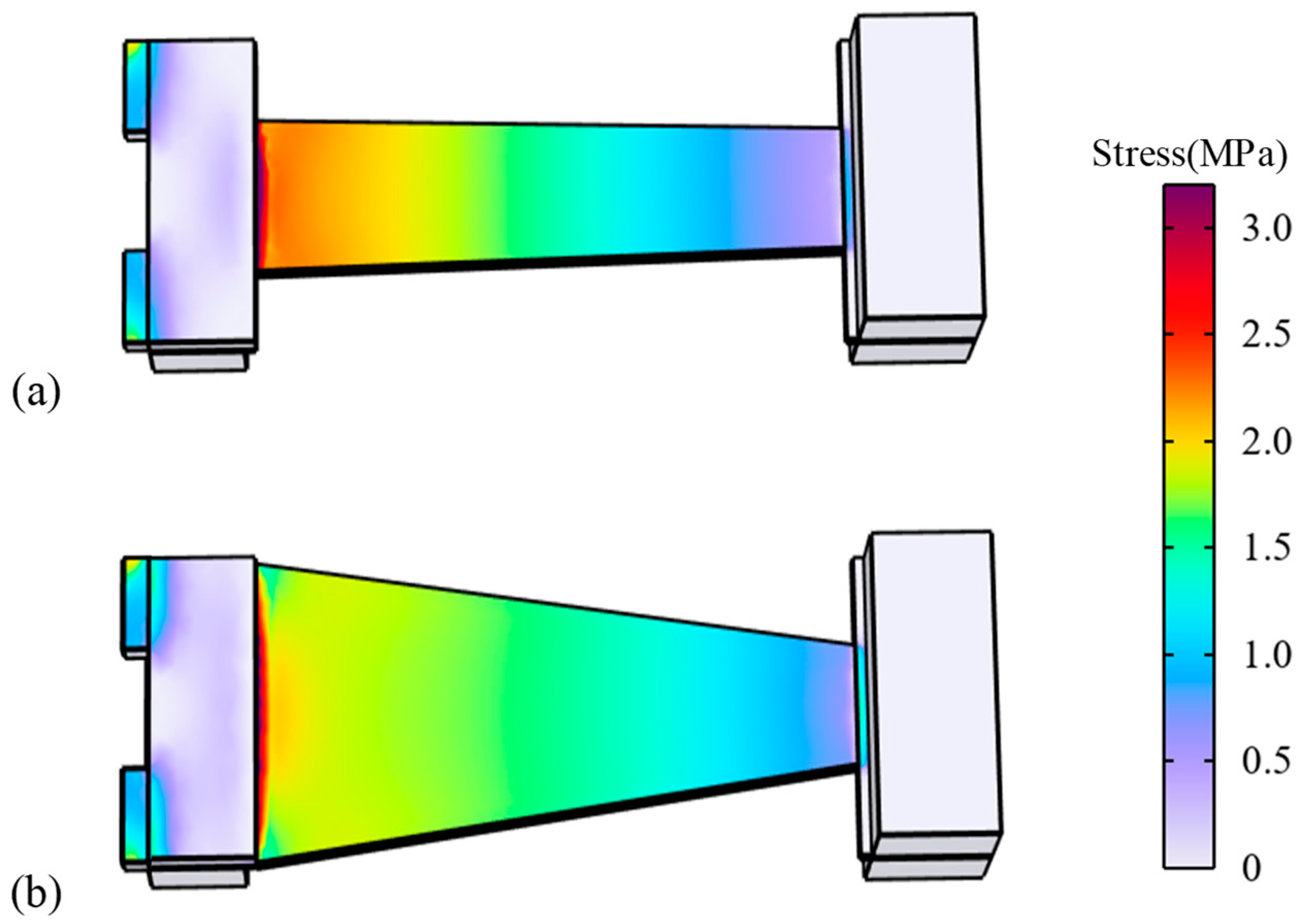
A finite element simulation of an electromechanical coupled multi-physical distributed parameter model is established to calculate the open-circuit voltage and characteristic frequency of the non-uniform cross-section model resulting from varying the widths at both ends of the cantilever beam. Using the finite element simulation software COMSOL v.6.2, set the boundary conditions with the fixed-support auxiliary base at the left end of the cantilever beam and the voltage on the inner surface of the piezoelectric sheet in parallel to be zero. The linear elastic small deformation model of the piezoelectric component and axial stress along the length direction of
x in a steady state, when the tip mass at the active end on the right is subjected to the static force
F of 0.4 N in the form of the volumetric load based on analysis of Equation (8), is shown in
Figure 10.
From the stress distribution contour map in
Figure 10, it can be observed that the extension of the fixed end reduces the level of stress under the same excitation, consistent with theoretical analysis based on Equation (8). And under the linear elastic deformation model, stress and strain are proportional, which exhibit a similar distribution pattern. The widths change
of the upper and lower edges are limited to within 20 mm, with the initial condition being a rectangular cantilever beam width of 20 mm. The widths of the fixed end and the movable end are also denoted as
b1 and
b2, respectively. Let the change in size of the fixed or movable end be denoted as
, add or subtract
from
b1, or
b2 will cause the open-circuit voltage and the natural frequency of the piezoelectric cantilever beam to change. Changing
b1 or
b2 could transform the cantilever beam from a rectangular structure to a trapezoidal structure, as shown in
Figure 9, where the width of the fixed end is typically greater than that of the active end in a trapezoidal cantilever beam. This is because the fixed end experiences greater stress than the active end, and a narrower fixed end is detrimental to the structural stability. Therefore, this paper adopts the approach of
b1 +
or
b2 −
to form the variable cross-section trapezoidal cantilever beam model in
Figure 10. Use the same piezoelectric cantilever beam simulation model in
Figure 10 to calculate the open-circuit voltage under the action of the static force
F and the modal analysis to calculate the natural frequency. Keep the excitation and tip mass the same, with the results shown in
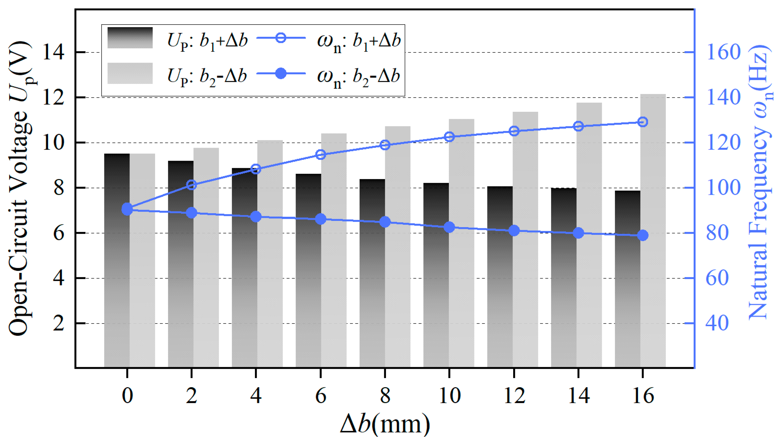
Figure 11.
The simulation results in
Figure 11 indicate that during the process of increasing the fixed end
b1, the open-circuit voltage output of the piezoelectric component gradually decreases, while the natural frequency of the piezoelectric cantilever beam structure gradually increases. Conversely, during the process of decreasing the active end
b2, the opposite characteristics are observed, which aligns with the analysis of the aforementioned theoretical model. And all the simulation results converge successfully, achieving the tolerance requirement of 1 × 10
−6 after thirteen iterations.
Taking the process of increasing the fixed end in
Figure 11 as an example, under the condition that the applied force
F remains constant, the piezoelectric cantilever beam undergoes linear elastic small deformations. Then, according to the analysis using Equations (8)–(10), the reduction in stress and strain distribution is offset by the increase in the surface area of the piezoelectric layer, resulting in nearly unchanged total surface charge on the piezoelectric component’s surface. Meanwhile, the increased surface area of the piezoelectric layer leads to an increase in the equivalent capacitance between the upper and lower surfaces, causing a decrease in the open-circuit voltage. Consistent with the theoretical model, this does not imply that strain changes the equivalent capacitance, but rather that widening
b1 increases the equivalent capacitance. Regarding the natural frequency, the process of increasing
b1 gradually increases the structural stiffness, which in turn leads to an increase in the characteristic frequency. As mentioned earlier, increasing the natural frequency will accordingly enhance the output current. During the process of increasing the piezoelectric cantilever beam
b1, the voltage decreases, while the current correspondingly increases, allowing for the existence of suitable dimensions that can enhance the output power. It could be achieved by testing the output power through experiments; thus, the optimization of piezoelectric components is also achieved. Furthermore, the process of decreasing the active end
b2 can be explained in the same manner.


