Article

Effects of Installation Angle on Energy Harvesting Performance of Airfoil-Based Piezoelectric Energy Harvester

School of Mechanical and Electrical Engineering, Guilin University of Electronic Technology, Guilin 541004, China
*
Author to whom correspondence should be addressed.
Appl. Sci. 2025, 15(3), 1366; https://doi.org/10.3390/app15031366
Submission received: 24 November 2024 / Revised: 22 January 2025 / Accepted: 27 January 2025 / Published: 28 January 2025

Abstract

:
This study introduces a novel optimization approach for airfoil-based flutter energy harvesters through installation angle adjustment, addressing a critical research gap in the field where previous studies have primarily focused on structural modifications. To investigate this unexplored avenue, we developed a flutter energy harvester with an adjustable installation angle mechanism, aiming to reduce critical flutter velocity, broaden operational bandwidth, and improve energy harvesting efficiency under low-speed airflow conditions. The performance characteristics of the harvester were comprehensively evaluated through both numerical simulations incorporating fluid–structure-electrical coupling and wind tunnel experiments conducted at four distinct installation angles (0°, 3°, 6°, and 9°). The experimental results demonstrated a significant correlation between installation angle and critical flutter velocity, showing a consistent reduction from 7.8 m/s at 0° to 7.2 m/s at 6°, and further decreasing to 6.3 m/s at 9°. Notably, optimal performance was achieved at a moderate installation angle of 3°, yielding a maximum output voltage of 12.0 V and power output of 0.58 mW, which substantially exceeded the baseline performance at 0° (10.9 V, 0.48 mW). However, further increasing the installation angle to 9° led to performance degradation, attributed to a premature aerodynamic stall, resulting in reduced output metrics of 7.9 V and 0.25 mW for voltage and power, respectively. These findings demonstrate a simple yet effective method for enhancing flutter energy harvesting performance in low-speed airflow conditions.

1. Introduction

Flow-induced vibration (FIV) is a common source of vibration in nature. Since its discovery by von Kármán, this phenomenon—which is widely observed in flow environments—has attracted significant attention from researchers. FIV occurs when periodic vortices are generated as fluid flows past bluff bodies, creating alternating low-pressure regions behind them and resulting in vibrations. Numerous studies have investigated this phenomenon [1,2,3]. The main forms of FIV include vortex-induced vibration (VIV), galloping, and flutter. Flutter, as a self-excited vibration characterized by large amplitude oscillations [4,5], occurs when the flow velocity surpasses a critical threshold and has been extensively studied due to its significant impact on the stability of aircraft wings and blades [6,7].
In recent decades, driven by the pursuit of clean energy, researchers have investigated utilizing specialized devices to convert the mechanical energy from flow-induced vibrations into electrical energy, thereby exploring novel energy harvesting methods [8,9,10]. The common methods for converting vibration energy into electrical energy include piezoelectric energy harvesters [11,12], electromagnetic energy harvesters [13,14], electrostatic energy harvesters [15,16], and triboelectric energy harvesters [17,18]. Among these, piezoelectric harvesters have emerged as a prominent research focus due to their simplicity and high-power output [19,20].
Given that flutter possesses substantial energy potential, it has been investigated for possible applications in energy harvesting [21,22]. To understand the mechanisms of flutter-based piezoelectric energy harvester systems, researchers have employed theoretical analyses, experiments, and numerical simulations to explore the impact of various physical parameters on harvester performance. Zhen [23] utilized the lattice method and beam theory to establish a fluid–solid coupling model, examining the influence of the airfoil-based’s aspect ratio on harvester performance and validating the findings through experiments. Their results indicated that a wider airfoil-based harvester accelerates the onset of limit cycle oscillations (LCOs). Elahi [24] compared the effects of steady aerodynamics, unsteady formulations, and unsteady-state aerodynamics on computational accuracy, demonstrating that unsteady-state aerodynamics yield the highest accuracy. Tian [25] compared the accuracy of quasi-steady representations, unsteady formulations, and dynamic stall models, concluding that unsteady formulations offer superior accuracy. Furthermore, Tian studied the impact of elastic coefficients on the performance of airfoil-based flutter energy harvester systems, revealing that lower pitch elastic coefficients and moderate plunge elastic coefficients enhance system performance.
To further enhance the performance of airfoil-based piezoelectric energy harvester systems, researchers have explored innovative approaches by incorporating strategic accessories to optimize system performance. Shan et al. [26] developed a novel configuration by integrating a cantilever beam and a cylindrical bluff body into an airfoil-based flutter energy harvester system. The researchers strategically placed a piezoelectric ceramic transducer (PZT) on the cantilever beam to expand the system’s operational capabilities. Their proposed design demonstrates remarkable versatility: at velocities below the critical threshold, the cylindrical bluff body effectively induces VIV; while at velocities exceeding the critical point, it triggers limit cycle oscillations (LCOs) in the flutter energy harvester system. This dual functionality significantly improves output power generation during both VIV and LCO conditions. Following this approach, Li et al. [27] developed an innovative piezoelectric energy harvester system featuring a centrally positioned cylindrical bluff body and symmetrically arranged airfoil-based structures. This design effectively achieves a synergistic coupling of VIV and flutter energy harvesting mechanisms, resulting in superior performance compared to individual system configurations. Wang et al. [28] advanced the field by comprehensively investigating airfoil-based flutter energy harvester systems equipped with flaps. Through a multi-methodological approach that included theoretical derivations, computational simulations, and experimental validation, their study revealed an important insight: the implementation of inelastic constraint flaps fundamentally alters the vibration characteristics of the harvester. Specifically, the system transitions from flutter behavior at low velocities to VIV as the velocity increases, thereby reducing the critical flutter velocity. In a related study, Tian et al. [29] conducted a detailed examination of flap installation angles, demonstrating that these angles significantly influence the vortex-shedding dynamics of the airfoil-based harvesters. Their findings confirmed that smaller installation angles consistently enhance system performance, providing valuable design guidance for future energy harvester configurations.
Beyond integrating mechanical accessories, researchers have investigated the incorporation of magnetic forces as an alternative strategy to improve energy harvester efficiency. Iqbal [30] introduced a novel airfoil-based flutter energy harvester system that simultaneously integrates piezoelectric and electromagnetic energy conversion modes. This innovative approach enables concurrent energy extraction from both structural- and flow-induced vibrations, thus substantially enhancing the system’s overall performance potential. Li et al. [31] extended this concept by designing a piezoelectric–electromagnetic hybrid flutter energy harvester. By utilizing a semi-empirical nonlinear aerodynamic model and a magnetic dipole model, they observed that when magnets are positioned in close proximity, an amplitude jump occurs, significantly amplifying the output power of the electromagnetic component near a critical point. Building upon these approaches, Tian et al. [32] conducted a comprehensive investigation of airfoil-based flutter energy harvesting devices, systematically analyzing the effects of various magnet installation distances through theoretical derivations, computational simulations, and experimental methods. Their findings demonstrated the profound impact of a strategic magnet arrangement, showing that an optimized configuration can reduce the critical flutter velocity by up to 80% while achieving an 82.6% increase in output power generation, marking a significant advancement in energy harvester design and performance optimization.
Previous research on airfoil-based flutter piezoelectric energy harvester systems has primarily concentrated on structural design and theoretical foundations, with relatively limited scope. The mounting angle, despite being a crucial parameter in these systems, has received insufficient attention in existing literature. Given that the mounting angle is an essential installation parameter in practical applications, there is a critical need to investigate its effects systematically. To address this research gap, we employ numerical simulation methods to examine the influence of mounting angles on both the vibration dynamics and energy harvesting performance of the airfoil-based flutter piezoelectric energy harvester system. To validate our computational approach, we conduct empirical experiments using a prototype system in a specialized wind tunnel setup. This study aims to comprehensively investigate the impact of mounting angle variations on the system’s vibration characteristics and energy harvesting efficiency. Based on established aerodynamic principles for determining wing angle of attack, we systematically selected three mounting angles: 3°, 6°, and 9°, representing a progressive range from small to large angles. A system configuration with a 0° mounting angle serves as the baseline control case. Through this comparative analysis of four distinct configurations of the airfoil-based flutter piezoelectric energy harvester system, we seek to provide a detailed understanding of how mounting angle variations affect system performance.
The manuscript follows a logical and thorough progression of scientific investigation. Section 2 presents an in-depth introduction to the system’s structural configuration and the fundamental control equations, establishing the theoretical foundation for subsequent analyses. Section 3 details the numerical simulation methodology, including a comprehensive exposition of the computational approach and a rigorous analysis of the computational outcomes. In Section 4, we present empirical investigations of the vibration response characteristics and output performance of the airfoil-based flutter energy harvester system through systematic wind tunnel experiments. Finally, Section 5 synthesizes the key findings, presents substantive conclusions, and suggests potential future research directions, providing a comprehensive overview of the study’s scientific contributions.

2. Airfoil-Based Flutter Energy Harvester System Design and Control Equations

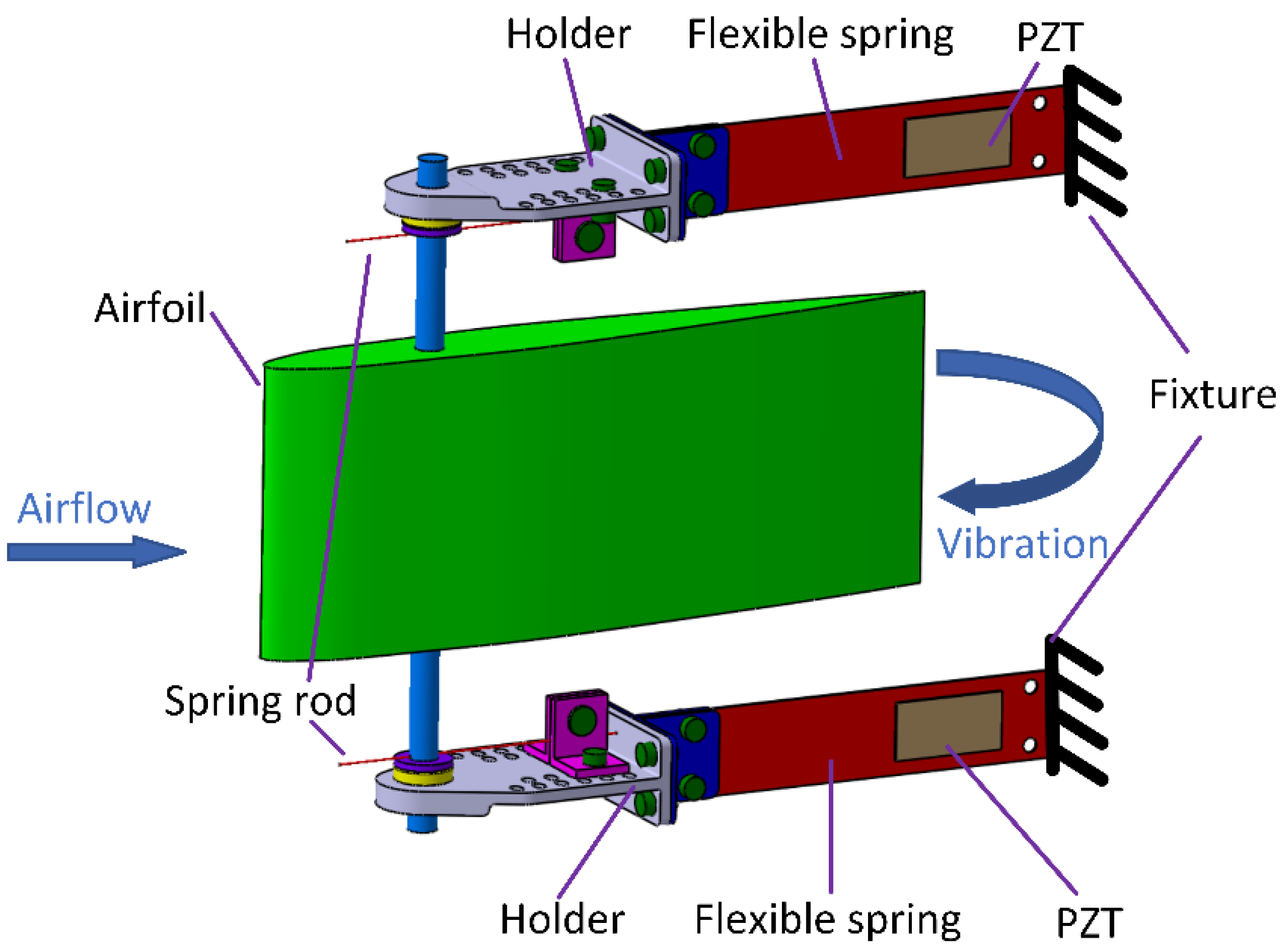
2.1. Conceptual Designing

In airfoil-based flutter piezoelectric energy harvester systems, when the airflow velocity exceeds a critical threshold, aeroelastic coupling induces flutter motion characterized by coupled plunge–pitch oscillations. Based on this fundamental principle and the structural designs reported in [28,29], we designed a novel energy harvesting system, as illustrated in Figure 1. The proposed system consists of several key components: an airfoil-based structure for aerodynamic force capture, a rotating pitch mechanism enabling controlled pitch motion, two fixed brackets for structural support, and dual elastic beams that facilitate plunge motion through their bending deformation. The system’s restoration mechanism is achieved through two spring rods connecting the rotating pitch component to the brackets, while energy conversion is accomplished by two PZTs mounted on the elastic beams. The material properties and structural dimensions of all components are listed in Table 1.
The working principle can be described as follows: As the ambient fluid velocity increases, the system experiences growing aerodynamic negative damping effects. When this negative damping overcomes the system’s inherent structural damping, the harvester enters a LCO state. During this state, the airfoil-based harvester undergoes sustained plunge–pitch oscillations: the plunge motion is facilitated by the elastic beam deformation, while the pitch motion is regulated by the spring-loaded rotating mechanism. These coupled oscillations induce cyclic strain in the PZTs, effectively converting the mechanical energy of flutter vibrations into electrical energy. This self-sustained oscillation mechanism enables continuous energy harvesting without external mechanical excitation, making it particularly suitable for sustained power generation in fluid flow environments.

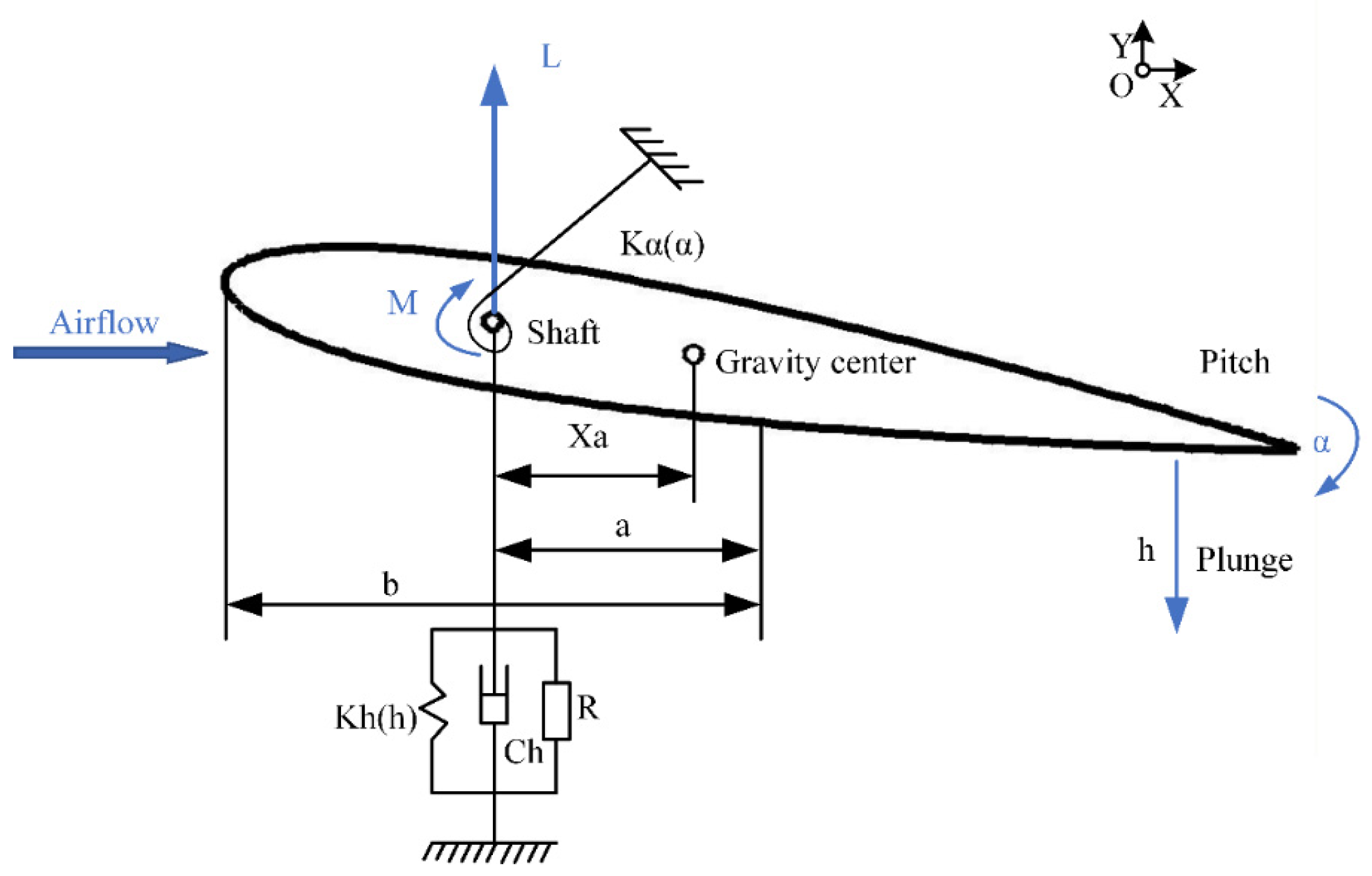
2.2. Governing Equations

Figure 2 illustrates a schematic diagram depicting the aerodynamic loads acting on the airfoil-based flutter piezoelectric energy harvester system. The motion model of this system is simplified to a “spring-mass-damping” system for descriptive purposes. The control equations governing the two-degree-of-freedom dive-pitch flutter piezoelectric energy harvester are derived, taking into account the piezoelectric effect. These control equations are formulated as follows [25,32]:
m T h ¨ + S α α ¨ + C h h ˙ + ( k h 0 + k h 2 h 2 ) h + θ V = L
S α h ¨ + I α α ¨ + C α α ˙ + ( k α 0 + k α 2 α 2 ) α = M
C p V ˙ + V R θ h ˙ = 0
where L is the longitudinal force, positive in the upward direction, M is the moment, positive in the counterclockwise direction, and h is the sudden displacement, positive in the downward direction; α represents the pitch displacement, positive in the clockwise direction; m t represents the total mass, including the airfoil-based components, plunge spring, spring rod, and holder; m f denotes solely the mass of the wing; I a is the mass moment of inertia about the elastic axis. C h and C α are the damping coefficients of the pitch and roll degrees of freedom, respectively; k h 0 and k α 0 represent the linear structural stiffness coefficients associated with the pitch and roll degrees of freedom, respectively; k h 2 and k α 0 represent the linear structural stiffness coefficients related to the cubic nonlinear pitch and roll degrees of freedom, respectively; θ is the harvester electromechanical coupling term; R represents the external load resistance connected to the piezoelectric sheet of the collector; V is the output voltage generated by the external resistor; C p represents the capacitance of the piezoelectric sheet; S α = m f X a b is the mass moment of the airfoil-based body about the rigid center; b represents the half chord of the airfoil-based -based; a denotes the dimensionless offset of the airfoil-based elastic axis measured from the half chord; X a is the dimensionless distance from the center of gravity to the elastic axis.
Table 2 presents a comprehensive summary of the parameters for the airfoil-based flutter piezoelectric energy harvesting system. These parameters can be classified into four distinct categories: (1) designated design parameters ( s , b and R ); (2) directly measured parameters ( m t , m f , a and X a ) obtained using standard measurement instruments; (3) dynamic parameters ( k h 0 , k α 0 , C h , and C α ) determined through free vibration experiments following Chen’s methodology [33]; and (4) theoretical parameters ( C p and θ ) of the PZT-5H piezoelectric material as provided by the manufacturer.

3. Multi-Physical Coupled Fields Simulation Analyses

3.1. Equations for Rigid Body Motion and Solution Methodology

In this study, a dual-degree-of-freedom model is employed to characterize the system’s motion. Given that the operational velocity of the system does not exceed 0.1 Mach, air is assumed to behave as an incompressible fluid. The numerical simulations are conducted using ANSYS FLUENT 2020R2. The computer’s CPU model utilized for the simulations is the Intel Xeon Silver 4216 with 16 cores (Intel, Santa Clara, CA, USA).
Since flow-induced vibration represents a typical transient problem, it is essential to account for the flow field phenomenon at each moment within a time period. Consequently, the unsteady Navier–Stokes equations are utilized to describe the flow. The control equation is expressed in dimensionless form as follows:
u i ¯ x i ¯ = 0
ρ u i ¯ t + ρ u i u j ¯ t = p x i + μ 2 u i ¯ ρ u i u j ¯ x j
where x i and x j are the Cartesian coordinates in the i and j directions, u i ¯ and u i ¯ are the time-averaged values of the corresponding instantaneous components of velocity and velocity wave term, ρ is the density of the fluid, μ is the dynamic viscosity of the fluid, p is the pressure, and ρ u i u j ¯ is the Reynolds stress tensor. To enhance the accuracy of the computational results, we employ the turbulence model proposed by Menter [31,32] to address the issue. This model incorporates a turbulent viscosity limit, which enhances the accuracy of calculations, particularly for backflow scenarios [34,35].
The pressure–velocity coupling in this study is achieved through the Coupled algorithm in FLUENT. This solver employs a fully implicit approach where pressure and velocity fields are solved simultaneously. Compared to the segregated solver, the Coupled algorithm demonstrates superior convergence characteristics and enhanced numerical stability. Although it requires more computational memory per iteration, this approach significantly reduces the total number of iterations needed for convergence, thereby improving overall computational efficiency.
In this paper, FLUENT User Defined Functions (UDFs) are employed to establish mesh motion, while the fourth-order Runge–Kutta method is utilized to solve the motion dynamics of the airfoil-based flutter energy harvester system. This approach enables the computation of linear displacement, linear velocity, angular displacement, and angular velocity of the system at each time step. The solution from the preceding iterative calculation serves as the initial condition for the subsequent step, facilitating mesh updates. The Runge–Kutta algorithm is implemented as follows:
y n + 1 = y n + y ˙ Δ t + Δ t 2 12 ( S 1 + 2 S 2 + 2 S 3 + S 4 )
S 1 = f ( x n , y n )
S 2 = f ( x n + 1 / 2 , y n + Δ t 2 S 1 )
S 3 = f ( x n + 1 / 2 , y n + Δ t 2 S 2 )
S 4 = f ( x n + 1 , y n + Δ t S 3 )
where x n represents a series of discrete nodes; y n represents the approximate solution corresponding to x n .
Since the airfoil-based flutter energy harvester system is 0 at the initial position h , h ˙ , α ˙ , α and V , the initial value problem of the second-order differential Equations (1)–(3) has the following expression
h ¨ = [ ( L + V θ ) I α / S α ( M C α α ˙ ( k α 0 + k α 2 α 2 ) α ) ] / ( m T I α / S α S α ) I α / ( m T I α S α 2 ) · ( C h h ˙ + ( k h 0 + k h 2 h 2 ) h )
α ¨ = [ M m T / S α ( L C h h ˙ ( k h 0 + k h 2 h 2 ) h θ V ) ] / ( m T I α / S α S α ) m T / ( m T I α S α 2 ) · ( C α α ˙ + ( k α 0 + k α 2 α 2 ) α )
V ˙ = ( h ˙ · θ ) V / ( C P R )
As depicted in Figure 3, the solution process proceeds as follows: (1) initialize the flow field; (2) use UDFs to calculate amplitude, velocity, angular velocity, and angular acceleration; (3) update the dynamic mesh; (4) when the calculation is completed, return to step (2) until the calculation is completed.
The numerical simulation domain consists of a rectangular region measuring 20b × 12b, as illustrated in Figure 4a. The boundary conditions are configured as follows: velocity inlet at the upstream boundary; pressure outlet at the downstream boundary; symmetric conditions at both upper and lower boundaries; and no-slip wall condition on the airfoil-based surface. To ensure mesh quality and capture flow characteristics accurately, a structured mesh strategy is employed, as shown in Figure 4b. Special attention is paid to the boundary layer region around the airfoil, where mesh refinement is implemented to resolve the near-wall flow physics. To handle the airfoil-based motion and prevent mesh distortion, a dynamic mesh technique is adopted, ensuring that the boundary layer mesh moves synchronously with the airfoil-based surface. The mesh update is performed at each time step according to the displacement calculated through the UDF framework.
For spatial discretization, the Green–Gauss node-based gradient method available in FLUENT is selected. This approach demonstrates superior accuracy for unstructured meshes, particularly in cases involving triangular elements and significant mesh size variations. The method proves especially effective in handling mesh deformation during boundary motion simulations.
In this study, ICEM CFD is utilized to generate a grid for computations. The grid’s Element Quality surpasses 0.4, while the skewness remains below 0.6. To guarantee calculation accuracy and efficiency, we examine grid independence for the airfoil-based flutter energy harvesting system at a mounting angle of 0° under a wind speed of 9 m/s. Three varying grid resolutions are established sequentially, with an increase in the number of grids. The first boundary layer mesh height strictly adheres to the criteria of y + 30 , where the boundary layer mesh growth rate is set at 1.2. The relationship between y + and y H is maintained as follows:
y H = 2 y + 0.0288 R e 0.2 U 2 μ
The calculation outcomes for the root mean square value of the lift coefficient and the root mean square value of the lift coefficient are detailed in Table 3. Analysis of the data reveals that the variance between the values of M2 and M3 is under 1.0%, signifying that the M2 grid has achieved full convergence. Consequently, we adopt the M2 grid strategy for grid construction in this research.

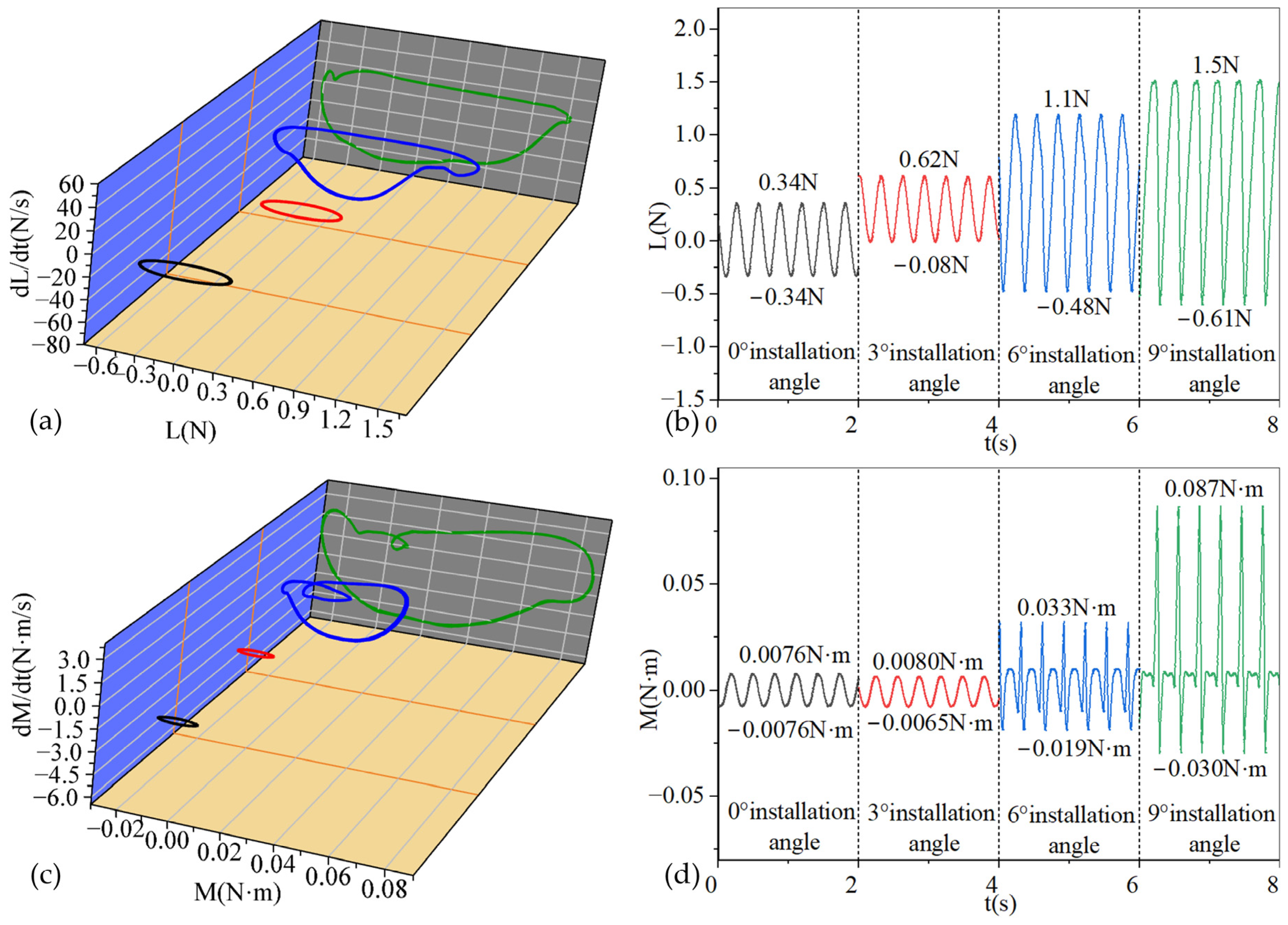
3.2. Aerodynamic Performance

Figure 5 presents a comprehensive analysis of the dynamic characteristics and energy harvesting performance of the airfoil-based piezoelectric flutter energy harvester under various installation angles and wind speeds. The experimental results reveal that the installation angle plays a crucial role in determining the system’s performance characteristics. Notably, the critical flutter speed demonstrates a consistent decreasing trend as the installation angle increases from 7.8 m/s at 0° to 7.6 m/s at 3°, further reducing to 7.2 m/s at 6°, and reaching 6.3 m/s at 9°. This systematic reduction in critical flutter speed significantly broadens the effective operating range of the energy harvester.
Figure 5a,b demonstrate the displacement and pitch angle characteristics of the airfoil-based flutter piezoelectric energy harvesting system at various installation angles (0°, 3°, 6°, and 9°). The analysis reveals that at wind speeds below 7.5 m/s, the system installed at 9° exhibits the highest displacement and pitch angle among all configurations; however, these performance parameters progressively decrease as wind speeds exceed 7.5 m/s, with a significant reduction observed beyond 8.5 m/s. The system behavior at the 3° installation angle closely mirrors that of the 0° configuration, particularly in terms of displacement characteristics, while their pitch angles remain similar at wind speeds below 10 m/s, though the 3° configuration demonstrates higher pitch angles at speeds exceeding 10 m/s. Within the specific wind speed range of 7.5–8.5 m/s, the 6° installation angle configuration achieves maximum displacement and pitch angle values; as wind speeds surpass 8.5 m/s, the performance metrics of the 6° configuration converge with those of the 3° setup.
Figure 5c presents the lift characteristics of the airfoil-based flutter piezoelectric energy harvesting system at various installation angles. The results demonstrate that as the installation angle increases, the wind speed required for the system to achieve greater lift decreases. However, as the wind speed continues to increase, the lift obtained by systems with different installation angles tends to converge. This phenomenon, when analyzed in conjunction with Figure 5a, explains why systems with larger installation angles can experience fluttering at lower wind speeds. Figure 5d illustrates the torque characteristics under different installation angles, showing that the torque generated by the system increases proportionally with the installation angle. The analysis reveals that the system with a 9° installation angle generates torque significantly higher than that of the 6° angle configuration, while the torque for the 6° installation angle is substantially higher than those observed at 3° and 0° angles. At wind speeds below 8.5 m/s, the torques generated by systems with 3° and 0° installation angles remain comparable; however, beyond this wind speed threshold, the torque for the 3° angle configuration becomes significantly higher than that of the 0° angle. Analysis of Figure 5b,c reveals that at higher wind speeds, the system with a 9° installation angle, despite generating higher torque, does not achieve larger pitch angles or lift.
Figure 5e,f demonstrate the energy output characteristics of the airfoil-based flutter piezoelectric energy harvesting system at different installation angles under varying wind speeds. At wind speeds below 7.5 m/s, the configuration with a 9° installation angle exhibits superior energy output capacity. However, this configuration’s performance significantly deteriorates when wind speeds exceed 8.5 m/s, resulting in the lowest energy output among all tested configurations. The 6° installation angle configuration generates higher energy output compared to the 3° and 0° configurations at wind speeds below 8.5 m/s, but its performance converges with that of the 0° configuration at higher wind speeds. The 3° installation angle configuration shows energy output characteristics comparable to the 0° configuration at wind speeds below 9 m/s; notably, it achieves the highest energy output capacity among all configurations when wind speeds surpass 9 m/s. These experimental results clearly indicate that configurations with smaller installation angles enhance the energy harvesting efficiency of the airfoil-based flutter energy harvesting system under high wind speed conditions.
Figure 6 illustrates the phase diagrams and time histories of displacement and pitch angle for the airfoil-based flutter piezoelectric energy harvesting system at 8 m/s wind speed under varying installation angles. The results demonstrate that increasing installation angles leads to a progressive shift in neutral points away from zero for both displacement and pitch angle measurements. Notably, the system exhibits significantly larger displacement and pitch angle amplitudes at 6° and 9° installation angles compared to those at 0° and 3°. At the 3° installation angle, the maximum positive displacement shows an increment of 0.0007 m relative to the 0° configuration, while the maximum negative displacement decreases by 0.0018 m, resulting in a larger overall displacement amplitude at 0° installation angle. Interestingly, at the 9° installation angle, while the displacement magnitude decreases compared to the 6° configuration, the pitch angle demonstrates a larger amplitude. This observation aligns with the trends presented in Figure 5, where the displacement at the 9° installation angle becomes progressively smaller than that at 6° as wind speed increases. This phenomenon can be attributed to stall occurrence at this specific wind speed under a 9° installation angle, effectively limiting the displacement. Stall, characterized by a sudden reduction in lift force despite increasing pitch angle beyond the critical stall angle, fundamentally alters the system’s aerodynamic behavior.
Figure 7 illustrates the phase diagrams and time histories of lift and moment magnitudes for the airfoil-based flutter piezoelectric energy harvesting system operating at a wind speed of 8 m/s under varying installation angles. The analysis reveals that the lift and moment magnitudes at the installation angles of 6° and 9° substantially exceed those observed at 0° and 3°. Within each oscillation cycle, the systems with 6° and 9° installation angles demonstrate distinct characteristics, manifesting in sharp fluctuations of both lift and moment. These abrupt variations effectively constrain the pitch angle increment, which explains the observed phenomenon in Figure 5b,d, where despite experiencing larger moments, the systems with 6° and 9° installation angles did not achieve correspondingly higher pitch angles. Furthermore, the system configured at a 9° installation angle exhibits more pronounced moment fluctuations, consequently resulting in a reduced pitch angle compared to the 6° configuration.
Figure 8 presents the phase diagrams and time histories of the output voltage for the airfoil-based flutter piezoelectric energy harvesting system operating at a wind speed of 8 m/s under different installation angles. The analysis reveals that the output voltage waveforms exhibit predominantly sinusoidal characteristics. Under these operating conditions, the output voltage magnitudes show that the system with a 6° installation angle produces the highest output, followed by the 9°, 0°, and 3° configurations. This voltage magnitude relationship corresponds to the displacement and pitch angle trends observed in Figure 6 and Figure 7.

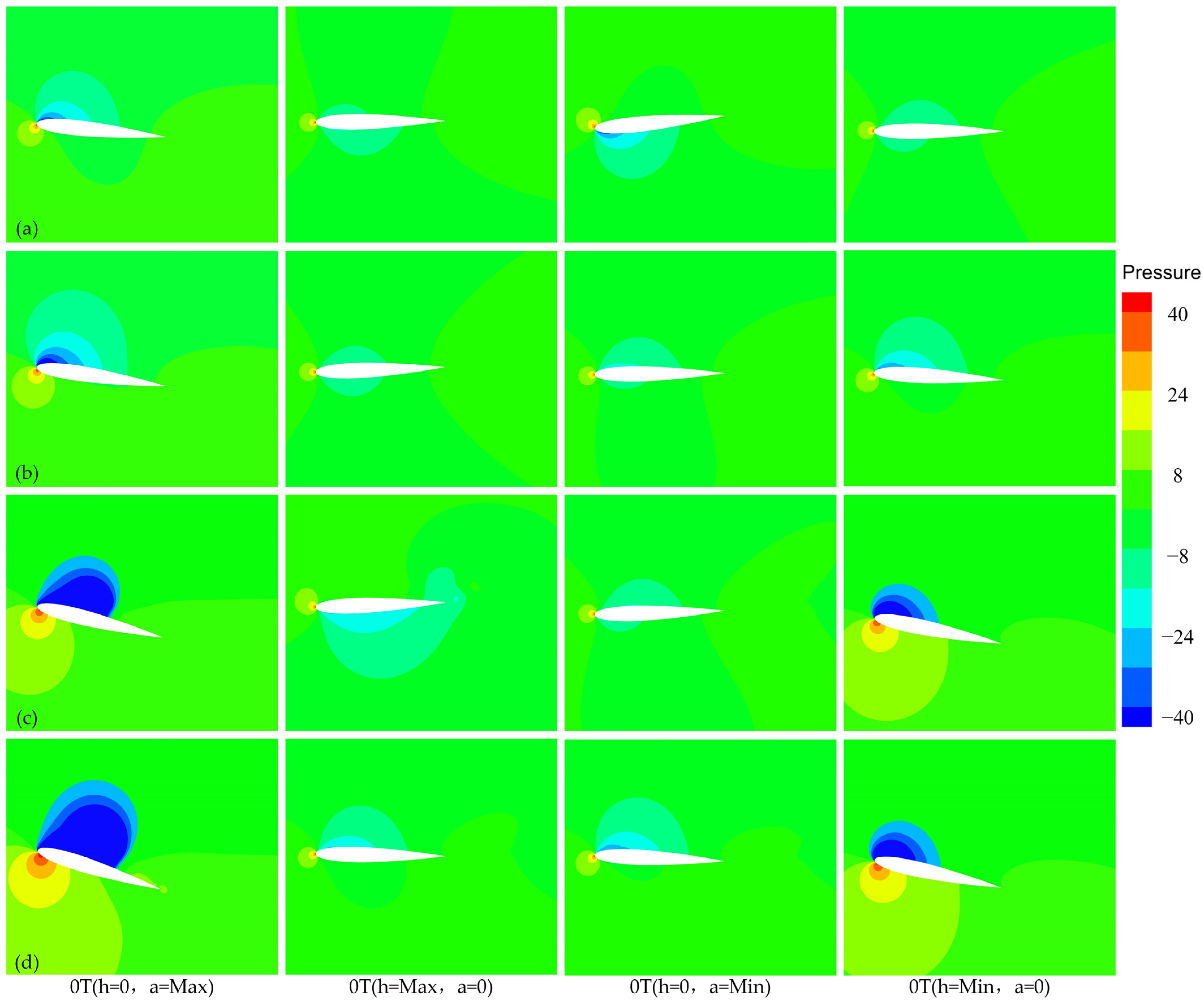
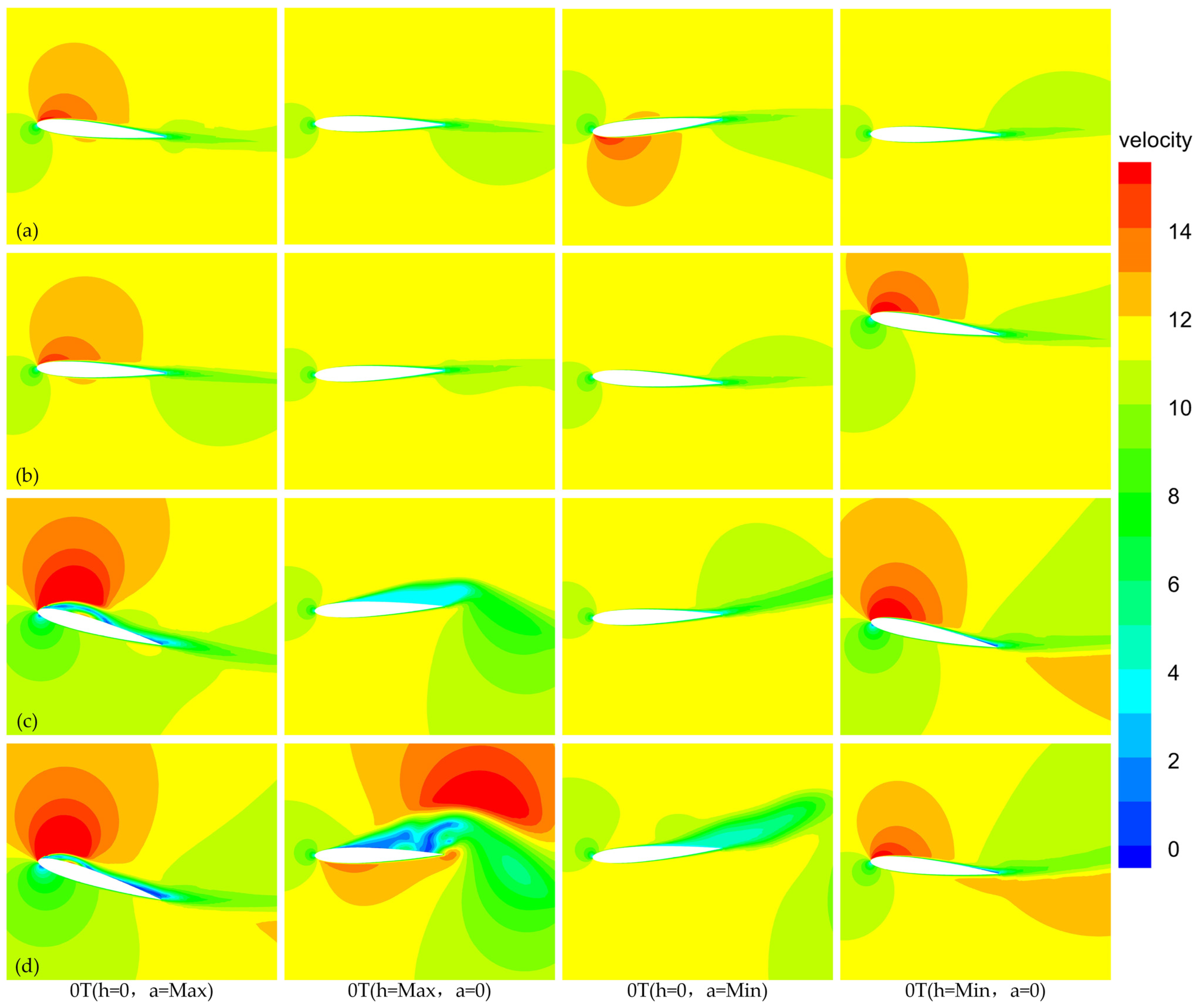
3.3. Visualized Analysis

To further investigate the aerodynamic mechanism and elucidate the phenomena observed in Section 3.2, a comprehensive comparative analysis was conducted on the flow characteristics of the airfoil-based flutter piezoelectric energy harvester system under a constant incoming flow velocity of 8 m/s. Figure 9 and Figure 10 illustrate the pressure distributions and velocity profiles under four mounting angles during one vibration cycle.
For the case of the 0° mounting angle (Figure 9a and Figure 10a), the flow field exhibits symmetric characteristics. A low-pressure region coupled with high-velocity flow alternately develops near the leading edge of the upper and lower surfaces at maximum and minimum angles of attack, respectively, corresponding to peak aerodynamic force generation. In contrast, at a 3° mounting angle (Figure 9b and Figure 10b), the flow field demonstrates significant asymmetry, with more pronounced low-pressure regions and higher flow velocities at the maximum angle of attack, while these effects are substantially weakened during the downward motion. This asymmetric behavior aligns with the kinematic data in Figure 6, where the energy harvester achieves an 8.4° maximum angle of attack during upward motion but only 2.2° during downward motion, resulting in predominant energy harvesting during the upward phase.
At higher mounting angles of 6° and 9° (Figure 9c,d and Figure 10c,d), the system experiences a local stall during its motion cycle, with notable flow separation at maximum angle of attack. This phenomenon is particularly severe at a 9° mounting angle, where flow separation persists even as the angle of attack decreases toward 0°, leading to reduced displacement and voltage output capabilities compared to the 6° configuration. However, comparative analysis of Figure 9a–d reveals that increasing mounting angles generate greater lift at 0° angle of attack, providing enhanced excitation for flutter initiation, which explains the observed decrease in critical velocity with increasing mounting angle as shown in Figure 5.

4. Experimental Investigation of Aeroelastic Vibration and Harvesting Performance

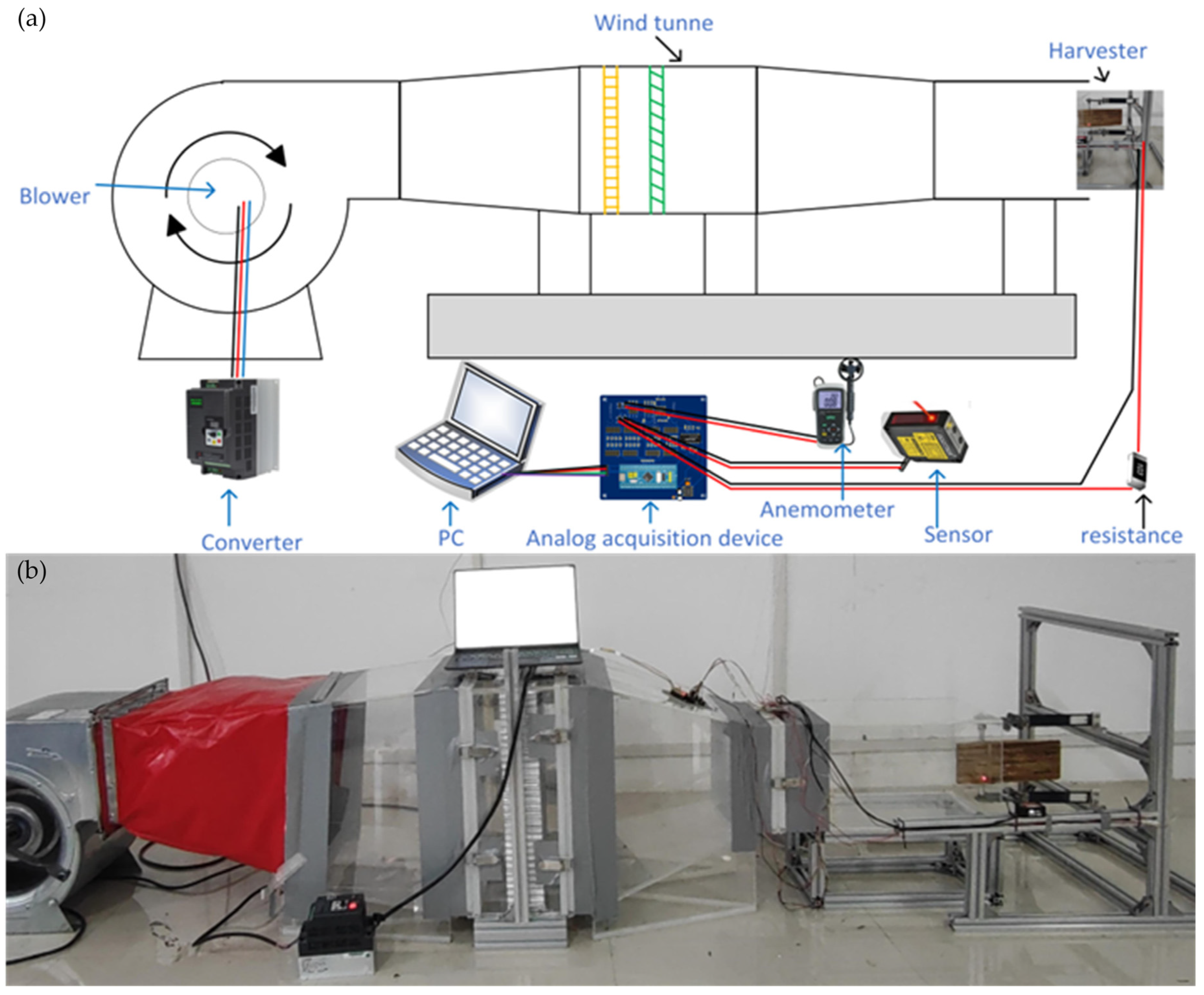
4.1. Experimental Setup

The experimental apparatus for the airfoil-based flutter piezoelectric energy harvester systems was constructed in a controlled laboratory environment, as illustrated in Figure 11. The core component—an energy collection system—was mounted vertically in the test section using a specialized support mechanism to ensure stability and precise positioning.
The experiments were conducted in an open-circuit wind tunnel facility housed within an enclosed laboratory space. To maintain accurate flow conditions, a calibrated pitot-static tube was installed at the tunnel inlet for continuous velocity monitoring. The experimental configuration was carefully designed to minimize flow interference, with adequate downstream distance between the test section and the laboratory wall to prevent flow recirculation. The energy harvesting system was installed in the test section through the access panel, with precise alignment relative to the freestream flow direction. To ensure reliable results and minimize wall interference effects, the system was designed with a blockage ratio below 5%, and no-slip boundary conditions were implemented on both the tunnel walls and airfoil-based surfaces.
To validate the computational results presented in Section 3, the experimental protocol began with constraining the movable components of the energy harvester. Upon establishing steady-state flow conditions at the designated test velocity, the constraints were systematically removed to allow free oscillation of the system. The measurement apparatus consisted of a high-precision laser displacement sensor with a 0.1 mm resolution for tracking instantaneous motion, coupled with a microcontroller-based data acquisition system providing a 0.00081 V voltage resolution. This integrated system simultaneously recorded both displacement measurements from the laser sensor and voltage output from the piezoelectric sheet, with all experimental data continuously acquired and stored in a digital format for subsequent analysis and comparison with computational results.

4.2. Experimental Validation

To validate the effectiveness of the numerical simulation methodology presented in Section 3, a comprehensive comparison between numerical and experimental results was conducted. Figure 12 presents the comparative analysis at installation angles of 0° and 9°. The results demonstrate excellent agreement between numerical predictions and experimental measurements, as shown in Figure 12a–f. However, some minor discrepancies were observed between the simulated and experimental values.
These differences can be attributed to several factors, primarily the inherent challenges in precisely replicating experimental conditions in numerical simulations, particularly regarding environmental parameters such as airfoil-based geometry and surface roughness characteristics. Furthermore, the flow field exhibits increasingly complex behavior at higher air velocities, characterized by significant deformations and pronounced nonlinear effects. These combined factors account for the slight variations observed in Figure 12a–d. Despite these minor discrepancies, the strong correlation between numerical and experimental results substantiates the reliability and accuracy of our simulation methodology.

4.3. Aeroelastic Vibration and Harvesting Performance

The experimental results highlight the substantial influence of the installation angle on the voltage output and overall performance of the airfoil-based flutter piezoelectric energy harvester systems. Figure 13 displays the voltage output and power curves of the airfoil-based energy harvester system as the velocity increases at various installation angles, including 0°, 3°, 6°, and 9°. Observations from the figure reveal that installation angles of 6° and 9° can lower the critical velocity. Specifically, the critical velocity at a 9° installation angle decreases to 6.3 m/s, while at a 6° installation angle, it decreases to 7.2 m/s. However, the 9° installation angle reduces the maximum output voltage and power. In comparison to the maximum output voltage of 10.9 V and maximum output power of 0.48 mW at a 0° installation angle, the maximum output voltage and power at a 9° installation angle decrease to 7.9 V and 2.5 mW, respectively. Conversely, installation angles of 3° and 6° can enhance the maximum output voltage and power. At a 3° installation angle, the system achieves an output voltage of 12.0 V and power of 0.58 mW, while at a 6° installation angle, it reaches an output voltage of 11.3 V and power of 0.51 mW. These results indicate that incorporating a moderate installation angle in the airfoil-based flutter energy harvester system can enhance its overall performance.

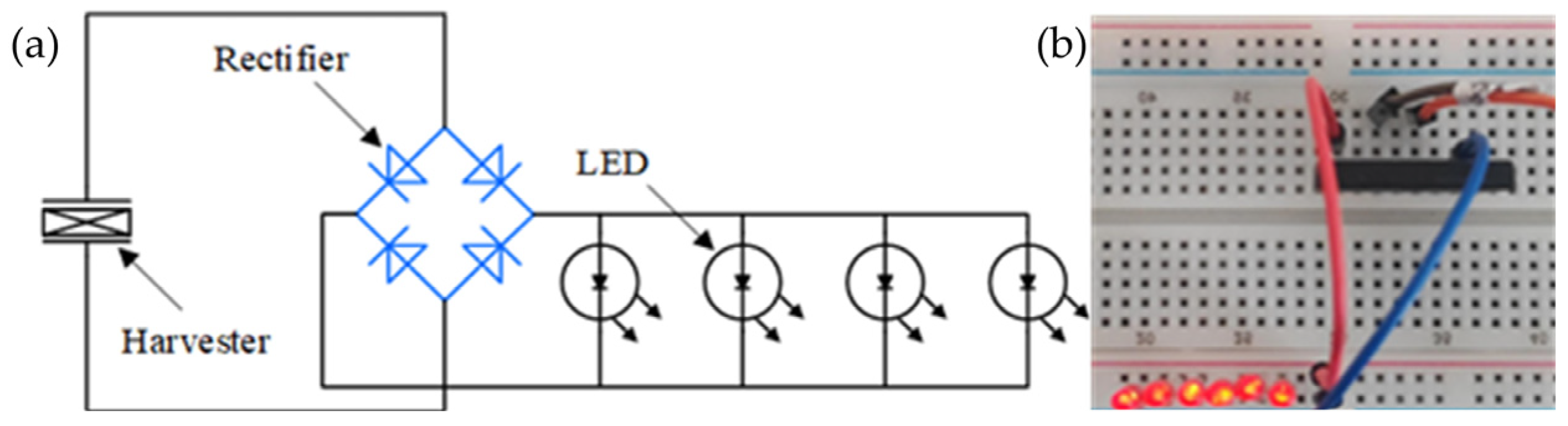
4.4. Field Harvesting Performance

To validate the energy harvesting capabilities of the airfoil-based flutter energy harvester system and to pave the way for its practical application, an energy harvesting circuit was meticulously designed, and experiments were conducted. The energy harvesting circuit, as illustrated in Figure 14, consists of a rectifier and a light-emitting diode (LED). The current generated by the airfoil-based flutter energy harvester system is rectified by the rectifier and subsequently utilized to power the LED. In Figure 14b, an experimental image showcases the airfoil-based flutter energy harvester system successfully powering six LED lamps at a velocity of 11 m/s. This demonstration serves as concrete evidence of the feasibility and functionality of the airfoil-based flutter energy harvester system, indicating its potential for practical applications in the future.

5. Conclusions

This study systematically investigates the performance characteristics of airfoil-based flutter piezoelectric energy harvesting systems at the installation angles of 3°, 6°, and 9°, using both numerical calculations and experimental methods. Taking the 0° configuration as the baseline, a detailed analysis is conducted to evaluate the effect of installation angle on system performance. The research, while conducted under controlled conditions, identifies several critical aspects that warrant further investigation for practical applications, including the influence of environmental factors (temperature and humidity) on energy harvesting efficiency, system resilience to disturbances in actual wind fields, and the impact of structural and material fatigue on long-term performance. Although these practical considerations require additional research, this study successfully establishes the fundamental relationship between installation angle and system performance under controlled conditions, providing a solid theoretical foundation for practical implementations. The main conclusions are as follows:
(1)
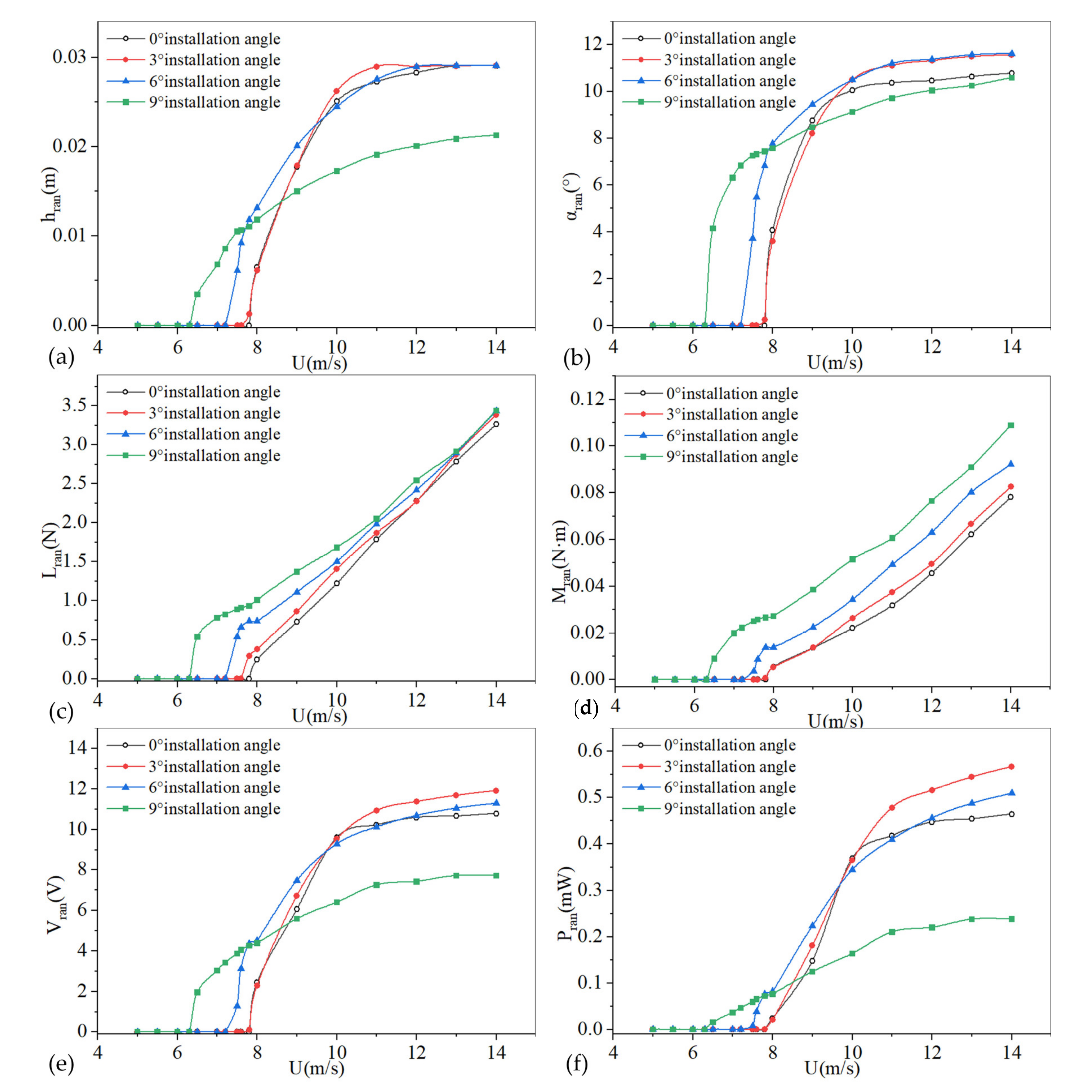
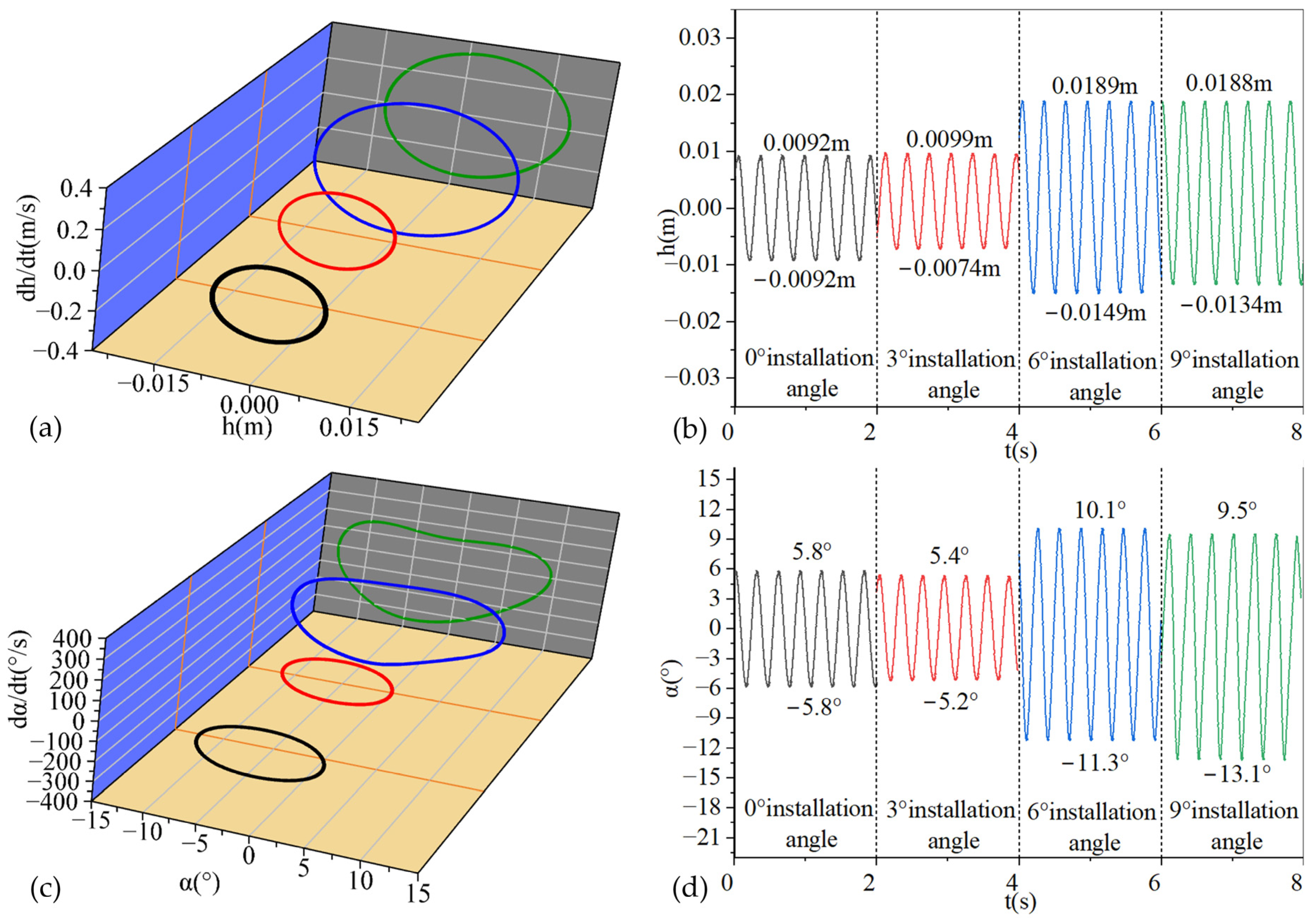
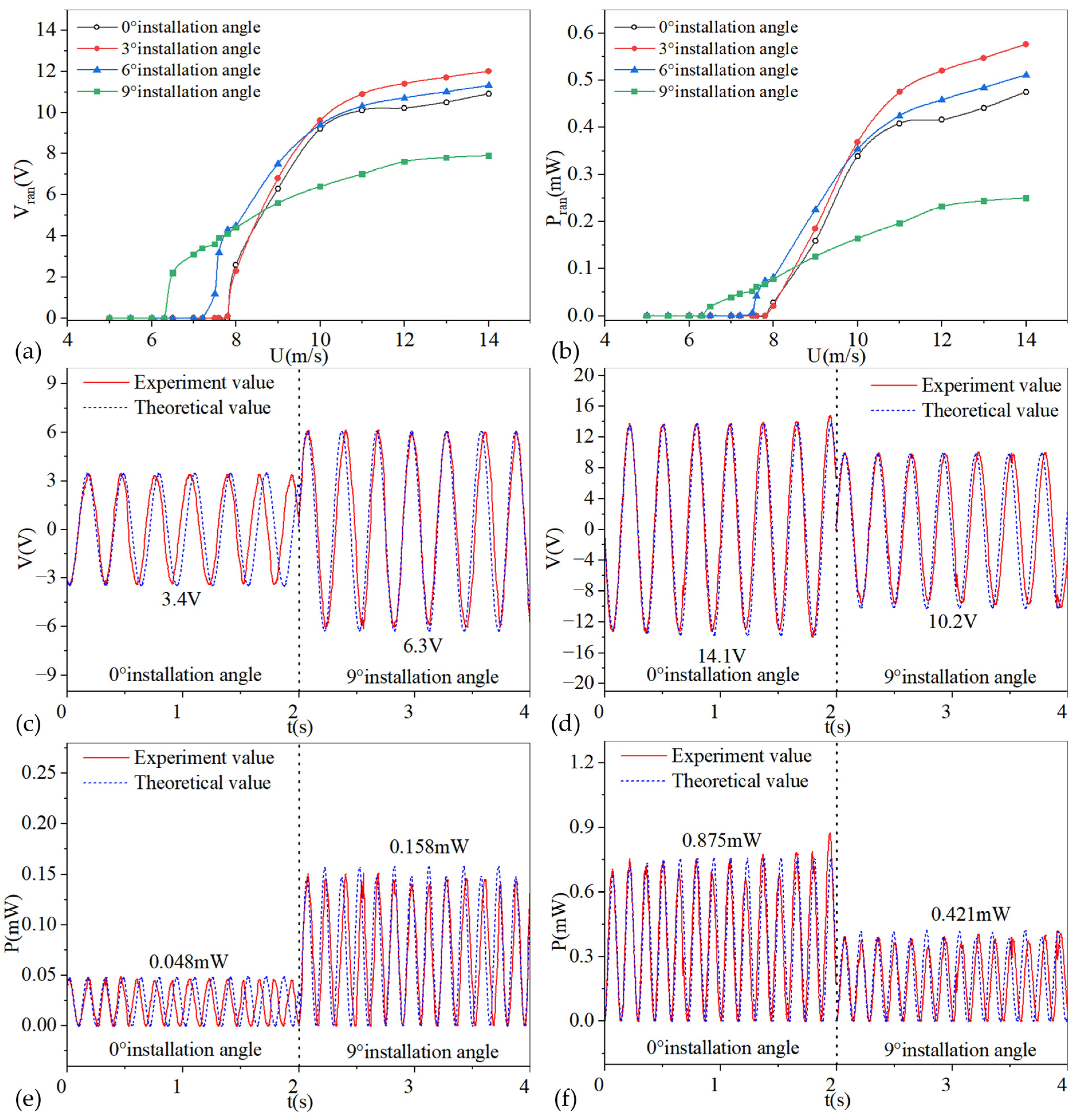
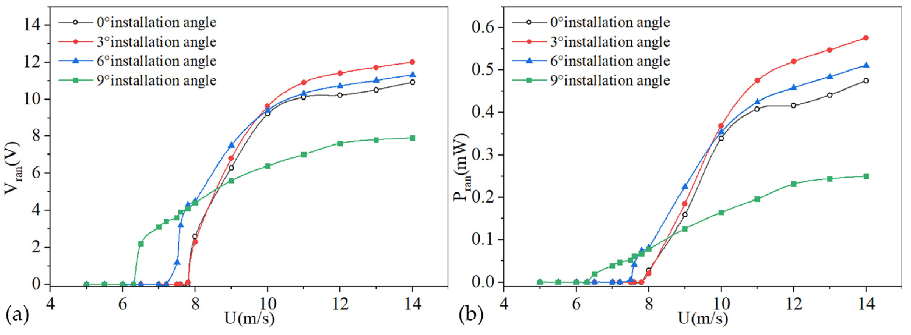
The installation angle is a crucial parameter influencing the critical flutter velocity of the airfoil-based piezoelectric energy harvester system. A clear inverse relationship exists between the installation angle and critical flutter velocity, with the latter decreasing from 7.8 m/s at 0° to 6.3 m/s at 9°. This systematic reduction in critical velocity can be attributed to enhanced initial lift generation at higher installation angles, which facilitates the earlier onset of flutter oscillations.
(2)
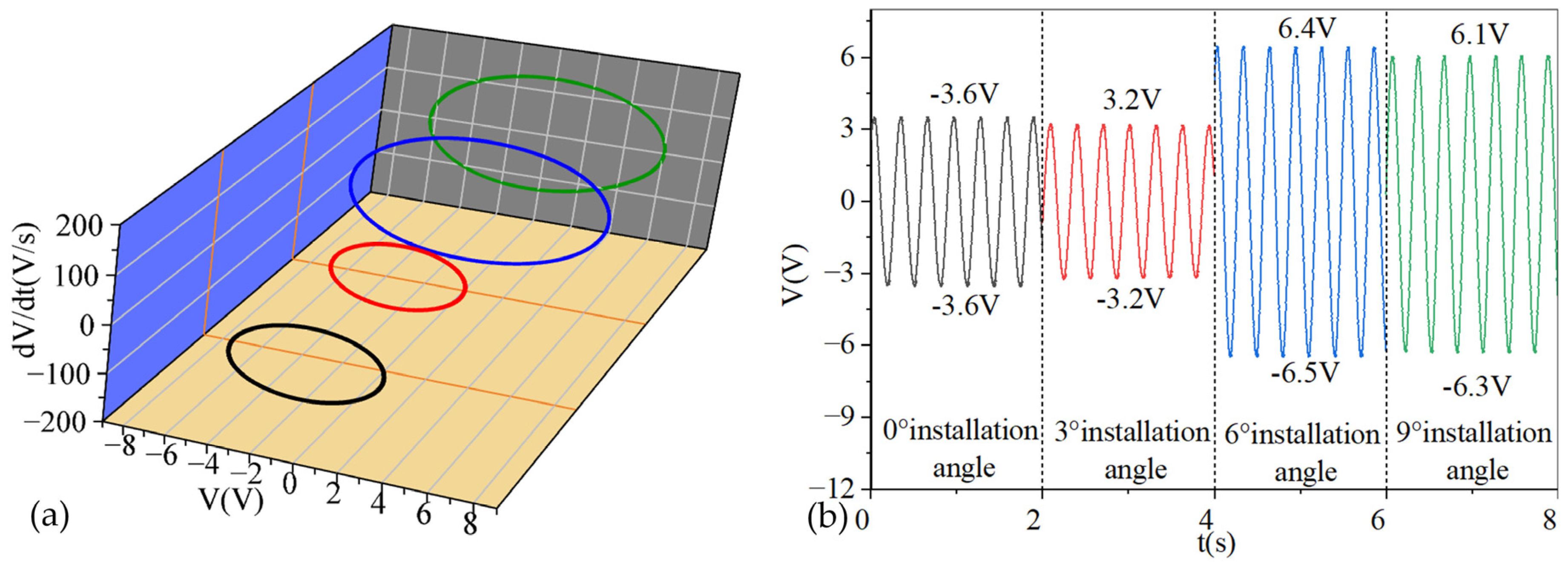
Moderate installation angles (3° and 6°) yield optimal energy harvesting performance. The system achieves maximum efficiency at a 3° installation angle, producing a peak output voltage of 12.0 V and power output of 0.58 mW, marking a substantial improvement over the baseline configuration at 0° (10.9 V, 0.48 mW). This enhanced performance stems from the development of favorable asymmetric flow field characteristics at moderate angles, enabling more efficient energy extraction from the airflow.
(3)
At higher installation angles, particularly at 9°, significant performance degradation occurs. Although this configuration achieves the lowest critical flutter velocity, it exhibits markedly reduced performance metrics (7.9 V voltage, 0.25 mW power). This deterioration is primarily due to the premature aerodynamic stall and persistent flow separation, highlighting a fundamental trade-off between reduced critical flutter velocity and maintained aerodynamic stability.
(4)
Installation angle adjustment represents an effective and practical approach to optimizing airfoil-based flutter energy harvesters, particularly in low-speed wind conditions. However, successful implementation necessitates careful consideration of the balance between reducing critical velocity and avoiding stall conditions. The results suggest that optimal performance can be achieved with moderate installation angles around 3° to 6°, providing valuable guidance for practical applications.

Author Contributions

R.T.: Writing—original draft, preparation, methodology, and software. D.L.: Formal analysis and writing—review and editing. Y.W.: Formal analysis and writing—review and editing. E.L.: Formal analysis and writing—review and editing. Z.Y.: Conceptualization and writing—original draft, preparation, Validation, methodology, and software. All authors have read and agreed to the published version of the manuscript.

Funding

This research was funded by the National Natural Science Foundation of China (Grant No. 52165010), and Guangxi Science and Technology Major Project (Grant No. GuiKeAA24206038).

Institutional Review Board Statement

Not applicable.

Informed Consent Statement

Not applicable.

Data Availability Statement

The raw data supporting the conclusions of this article will be made available by the authors on request.

Conflicts of Interest

The authors declare no conflicts of interest.

References

  1. Tang, R.; Wang, Q.; Gu, Y.; Wang, J.; You, Z.; Zhao, Y. Numerical study of wake induced vibration(WIV) and energy harvesting characteristics under different stable conditions. Energy 2024, 289, 129908. [Google Scholar] [CrossRef]
  2. Wang, J.; Sun, S.; Tang, L.; Hu, G.; Liang, J. On the use of metasurface for Vortex-Induced vibration suppression or energy harvesting. Energy Convers. Manag. 2021, 235, 113991. [Google Scholar] [CrossRef]
  3. Gu, Y.; Yurchenko, D.; Wang, J.; Li, S.; Wei, S.; Tang, R. Numerical analysis of reverse wake-induced vibration at low Reynolds number. Phys. Fluids 2023, 35. [Google Scholar] [CrossRef]
  4. Tian, H.; Shan, X.; Cao, H.; Xie, T. Enhanced performance of airfoil-based piezoaeroelastic energy harvester: Numerical simu-lation and experimental verification. Mech. Syst. Signal Process. 2022, 162, 108065. [Google Scholar] [CrossRef]
  5. Goyaniuk, L.; Poirel, D.; Benaissa, A.; Amari, H. The energy extraction potential from pitch-heave coupled flutter. J. Sound Vib. 2023, 555, 117714. [Google Scholar] [CrossRef]
  6. Chai, Y.; Gao, W.; Ankay, B.; Li, F.; Zhang, C. Aeroelastic analysis and flutter control of wings and panels: A review. Int. J. Mech. Syst. Dyn. 2021, 1, 5–34. [Google Scholar] [CrossRef]
  7. Yuan, W.; Zhang, X. Numerical Stabilization for Flutter Analysis Procedure. Aerospace 2023, 10, 302. [Google Scholar] [CrossRef]
  8. Ma, X.; Zhou, S. A review of flow-induced vibration energy harvesters. Energy Convers. Manag. 2023, 254, 115223. [Google Scholar] [CrossRef]
  9. Ma, X.; Li, Z.; Zhang, H.; Zhou, S. Dynamic modeling and analysis of a tristable vortex-induced vibration energy harvester. Mech. Syst. Signal Process. 2023, 187, 109924. [Google Scholar] [CrossRef]
  10. Li, J.; Wang, G.; Yang, P.; Wen, Y.; Zhang, L.; Song, R.; Hou, C. An orientation-adaptive electromagnetic energy harvester scavenging for wind-induced vibration. Energy 2024, 286, 129578. [Google Scholar] [CrossRef]
  11. Ali, A.; Ali, S.; Shaukat, H.; Khalid, E.; Behram, L.; Rani, H.; Altabey, W.; Kouritem, S.; Noori, M. Advancements in piezoelectric wind energy harvesting: A review. Results Eng. 2024, 21, 101777. [Google Scholar] [CrossRef]
  12. Naqvi, A.; Ali, A.; Altabey, W.A.; Kouritem, S.A. Energy harvesting from fluid flow using piezoelectric materials: A review. Energies 2022, 15, 7424. [Google Scholar] [CrossRef]
  13. Miao, G.; Fang, S.; Wang, S.; Zhou, S. A low-frequency rotational electromagnetic energy harvester using a magnetic plucking mechanism. Appl. Energy 2022, 305, 117838. [Google Scholar] [CrossRef]
  14. Fan, B.; Fang, J.W.; Zhao, J.C.; Li, C.; Wang, J.; Lv, M.M. Bionic flutter wing piezoelectric-electromagnetic composite energy harvesting system. Energy Convers. Manag. 2022, 271, 116319. [Google Scholar] [CrossRef]
  15. Chen, Y.; Cheng, Y.; Jie, Y.; Cao, X.; Wang, N.; Wang, Z.L. Energy harvesting and wireless power transmission by a hybridized electromagnetic–triboelectric nanogenerator. Energy Environ. Sci. 2019, 12, 2678–2684. [Google Scholar] [CrossRef]
  16. Tcho, I.-W.; Kim, W.-G.; Kim, J.-K.; Kim, D.-W.; Yun, S.-Y.; Son, J.-H.; Choi, Y.-K. A flutter-driven triboelectric nanogenerator for harvesting energy of gentle breezes with a rear-fixed fluttering film. Nano Energy 2022, 98, 107197. [Google Scholar] [CrossRef]
  17. Wang, J.; Geng, L.; Ding, L.; Zhu, H.; Yurchenko, D. The state-of-the-art review on energy harvesting from flow-induced vi-brations. Appl. Energy 2020, 267, 114902. [Google Scholar] [CrossRef]
  18. Lensvelt, R.; Fey, R.H.; Mestrom, R.M.C.; Nijmeijer, H. Design and numerical analysis of an electrostatic energy harvester with impact for frequency up-conversion. J. Comput. Nonlinear Dyn. 2020, 15, 051005. [Google Scholar] [CrossRef]
  19. Sezer, N.; Koç, M. A comprehensive review on the state-of-the-art of piezoelectric energy harvesting. Nano Energy 2021, 80, 105567. [Google Scholar] [CrossRef]
  20. Sitharthan, R.; Yuvaraj, S.; Padmanabhan, S.; Holm-Nielsen, J.B.; Sujith, M.; Rajesh, M.; Prabaharan, N. Piezoelectric energy harvester converting wind aerodynamic energy into electrical energy for microelectronic application. IET Renew. Power Gener. 2021, 15, 1968–1975. [Google Scholar] [CrossRef]
  21. Li, Z.; Zhou, S.; Yang, Z. Recent progress on flutter-based wind energy harvesting. Int. J. Mech. Syst. Dyn. 2022, 2, 82–98. [Google Scholar] [CrossRef]
  22. Li, S.; Chen, Z.; He, X.; Ye, Y.; Wan, S.; Dong, L. High performance hybrid omnidirectional wind energy harvester based on flutter for wireless sensing and hydrogen production applications. Nano Energy 2024, 132, 110403. [Google Scholar] [CrossRef]
  23. Rong, Z.; Cao, B.; Hu, J. Stability analysis on an aeroelastic system for design of a flutter energy harvester. Aerosp. Sci. Technol. 2017, 60, 203–209. [Google Scholar] [CrossRef]
  24. Elahi, H.; Eugeni, M.; Gaudenzi, P. Design and performance evaluation of a piezoelectric aeroelastic energy harvester based on the limit cycle oscillation phenomenon. Acta Astronaut. 2019, 157, 233–240. [Google Scholar] [CrossRef]
  25. Tian, H.; Shan, X.; Cao, H.; Song, R.; Xie, T. A method for investigating aerodynamic load models of piezoaeroelastic energy harvester. J. Sound Vib. 2021, 502, 116084. [Google Scholar] [CrossRef]
  26. Shan, X.; Tian, H.; Cao, H.; Xie, T. Enhancing performance of a piezoelectric energy harvester system for concurrent flutter and vortex-induced vibration. Energies 2020, 13, 3101. [Google Scholar] [CrossRef]
  27. Li, X.; Wang, X.; Tian, H.; Wang, C.; Liu, B. Experimental research of symmetrical airfoil-based piezoelectric energy harvester excited by vortex-induced flutter coupling. Appl. Sci. 2022, 12, 12514. [Google Scholar] [CrossRef]
  28. Wan, C.; Tian, H.; Shan, X.; Xie, T. Enhanced performance of airfoil-based piezoelectric energy harvester under coupled flutter and vortex-induced vibration. Int. J. Mech. Sci. 2023, 241, 107979. [Google Scholar] [CrossRef]
  29. Tian, H.; Shan, X.; Wang, H.; Li, X.; Su, Y.; Wang, J. Enhanced piezoelectric energy harvesting performance using trailing-edge flap. Ocean Eng. 2023, 285, 115443. [Google Scholar] [CrossRef]
  30. Iqbal, M.; Khan, F.U. Hybrid vibration and wind energy harvesting using combined piezoelectric and electromagnetic con-version for bridge health monitoring applications. Energy Convers. Manag. 2018, 172, 611–618. [Google Scholar] [CrossRef]
  31. Li, Z.; Zhou, S.; Li, X. A piezoelectric–electromagnetic hybrid flutter-based wind energy harvester: Modeling and nonlinear analysis. Int. J. Non-Linear Mech. 2022, 144, 104051. [Google Scholar] [CrossRef]
  32. Tian, H.; Shan, X.; Li, X.; Wang, J. Enhanced airfoil-based flutter piezoelectric energy harvester via coupling magnetic force. Appl. Energy 2023, 340, 120979. [Google Scholar] [CrossRef]
  33. Chen, Z.; Shi, Z.; Chen, S.; Yao, Z. Stall flutter suppression of NACA 0012 airfoil-based based on steady blowing. J. Fluids Struct. 2022, 109, 103472. [Google Scholar] [CrossRef]
  34. Menter, F.R. 2-EQUATION eddy-viscosity turbulence models for engineering applications. AIAA J. 1994, 32, 1598–1605. [Google Scholar] [CrossRef]
  35. Menter, F.R. A comparison of some recent eddy-viscosity turbulence models. J. Fluids Eng. 1996, 118, 514–519. [Google Scholar] [CrossRef]
Figure 1. Schematic diagram of airfoil-based flutter piezoelectric energy harvester system.
Applsci 15 01366 g001
Figure 2. Schematic of a piezoelectric harvester.
Applsci 15 01366 g002
Figure 3. The process of the numerical simulation.
Applsci 15 01366 g003
Figure 4. (a) Schematic diagram of the physical model; (b) meshing diagram of system.
Applsci 15 01366 g004
Figure 5. Variation in output characteristics with the installation angle: (a) root mean square displacement; (b) root pitch angle; (c) root mean square output lift; (d) root mean square moment; (e) root mean square output voltage; (f) root mean square output power.
Applsci 15 01366 g005
Figure 6. Variation in output characteristics with the installation angle under wind velocity of 8 m/s: (a) phase diagram of displacement; (b) time history of displacement; (c) phase diagram of pitch angle; and (d) time history of pitch angle.
Applsci 15 01366 g006
Figure 7. Variation in output characteristics with the installation angle under wind velocity of 8 m/s: (a) phase diagram of lift; (b) time history of lift; (c) phase diagram of moment; and (d) time history of moment.
Applsci 15 01366 g007
Figure 8. Variation in output characteristics with the installation angle under wind velocity of 8 m/s: (a) phase diagram of output voltage; (b) time history of lift.
Applsci 15 01366 g008
Figure 9. Pressure distribution diagram with the installation angle: (a) 0° installation angle; (b) 3° installation angle; (c) 6°installation angle; (d) 9° installation angle.
Applsci 15 01366 g009
Figure 10. Velocity distribution diagram with the installation angle: (a) 0° installation angle; (b) 3° installation angle; (c) 6° installation angle; (d) 9° installation angle.
Applsci 15 01366 g010
Figure 11. Wind tunnel experimental setup: (a) schematic diagram; (b) physical device.
Applsci 15 01366 g011
Figure 12. Output performance of the harvester system with and without installation angle obtained theoretically and experimentally: (a) output voltage versus airflow velocity; (b) output power versus airflow velocity; (c) time history of the output voltage at 8 m/s; (d) time history of the output voltage at 11 m/s; (e) time history of the output power at 8 m/s; (f) time history of the output power at 11 m/s.
Applsci 15 01366 g012
Figure 13. Experimental results of output characteristics changing with installation angle: (a) output voltage versus airflow velocity; (b) output power versus airflow velocity.
Applsci 15 01366 g013
Figure 14. Energy collecting and physical device of powering directly. (a) schematic diagram; (b) physical device.
Applsci 15 01366 g014
Table 1. Materials and dimensions parameters of the harvester system.
ParametersFlexural SpringPiezoelectric PatchHolderSpring Rod
MaterialsSpring steelPZT-5HAluminum alloy Glass fiber
Density (kg/m3)7850750028102500
Young’s modulus (GPa)210667273
Poisson’s ratio0.290.30.330.22
Length (mm)180409050
Width/Radius (mm)3020600.3
Thickness (mm)0.80.24-
Table 2. Dimensional parameters of the harvester.
PropertiesValue
Span, s (m)
Total   mass ,   m t (kg)
0.1
0.6
Airfoil - based   mass ,   m f (kg)0.18
Semi-chord, b (m)0.125
Position of the airfoil-based pitch relative to the semi-chord, a 0.5
Offset   of   airfoil - based   gravity   center ,   X a 0.335
Stiffness   coefficient   in   plunge ,   k h 0 (N/m)240
Stiffness   coefficient   in   pitch ,   k α 0 (0.28 Nm)0.28
Damping   coefficient   in   plunge ,   C h (kg/s)0.056
Damping   coefficient   in   pitch ,   C α (kg/s)0.056
Resistance, R (KΩ)250
Capacitance ,   C p (F)0.0000007
electromechanical coefficient of the harvester, θ (N/V)2.7 × 10−4
Table 3. Mesh independence validation.
MeshElementsA,rms (m)Change RateCl,rmsChange Rate
M157,3440.0164---0.5445---
M281,0970.01671.80%0.55942.66%
M3114,6890.01680.63%0.56280.61%
Disclaimer/Publisher’s Note: The statements, opinions and data contained in all publications are solely those of the individual author(s) and contributor(s) and not of MDPI and/or the editor(s). MDPI and/or the editor(s) disclaim responsibility for any injury to people or property resulting from any ideas, methods, instructions or products referred to in the content.

