Article

Influence of Blasting Approaches in In-Pit Haul Road Construction on Emission Levels and Resource Management: A Case Study from the Holcim “Dubie” Open-Pit Mine

by
Michał Dudek
1,*,
Michał Dworzak
2 and
Andrzej Biessikirski
2,*
1
KOSD Przedsiębiorstwo Produkcyjne PP Sp. z o.o. Sp. k., Grupa Holcim, ul. Legionów Polskich 105, 32-064 Rudawa, Poland
2
Faculty of Civil Engineering and Resource Management, AGH University of Krakow, Al. A. Mickiewicza 30, 30-059 Krakow, Poland
*
Authors to whom correspondence should be addressed.
Appl. Sci. 2025, 15(22), 12310; https://doi.org/10.3390/app152212310
Submission received: 30 October 2025 / Revised: 14 November 2025 / Accepted: 16 November 2025 / Published: 20 November 2025
(This article belongs to the Special Issue Advanced Blasting Technology for Mining)

Abstract

Transportation activities can constitute up to 70% of a quarry’s total operating costs, making haul roads a critical component of open-pit mine infrastructure. Generally, in-pit haul ramp construction can be accomplished through two primary blasting approaches: either peripheral blasting near the ramp location, or direct blasting at the designed ramp site. In the first method, the blasted material is transported, shaped, and compacted to form an embankment. Conversely, in direct blasting, the blast pattern is specifically designed to generate the ramp geometry, and the resulting muckpile is directed to production, eliminating the need for an embankment. Each method presents distinct operational advantages and inherent limitations. This study investigates the influence of these blasting scenarios, in particular on fume emissions (nitrogen oxides—NOx—and carbon oxides—COx) and deposit management. The assessment encompasses emissions generated both from the detonation of explosives and from the operation of diesel-powered equipment. The findings indicate that the method involving peripheral blasting (bench embankment construction method) produces more than 2.5 times higher nitrogen and carbon oxides emissions compared to blasting works at the exact construction location of the ramp at the Holcim Dubie dolomite open-pit mine. In addition to emission analysis, operational factors related to ramp formation and its subsequent use were evaluated. The results demonstrate that constructing the in-pit haul ramp directly within the rock mass yields approximately 2·106 Mg less fume emissions than the embankment-based method. Furthermore, this approach facilitates the recovery of an additional 150,000 m3 of dolomite for production purposes, thereby enhancing resource efficiency. Collectively, these findings suggest that the direct in-rock ramp construction technique offers superior environmental performance and operational sustainability within the context of open-pit mining practices.

1. Introduction

The design of haul roads for open-pit mines is a critical engineering facet that directly impacts the operational efficiency, safety, and economic viability of mining operations. Haul roads are specifically constructed routes intended to accommodate heavy mining trucks that transport ore, waste rock, and materials from extraction areas to processing facilities or disposal sites within the mine. The complexity of haul road design stems from the need to balance several factors, including geometric alignment, structural integrity, operational safety, and cost-effectiveness, in often challenging topographical and geotechnical conditions [1,2,3,4,5]. A number of studies posit that haulage can be responsible for 40–70% of total operational costs [6,7,8,9], with the fuel component being considered the primary factor [8,9,10]. Moreover, variations in haul road design parameters can significantly influence the final geometry of the open pit. This may further result in the excavation of additional volumes of overburden and waste material, or in the restriction of access to certain ore zones. Nevertheless, alternative methodologies for haul road and pit design are primarily directed toward maximizing the net economic value of the mining operation, commonly employing diverse numerical optimization techniques [7,11,12,13,14,15,16].
Fundamentally, haul road design involves the specification of geometric parameters such as road width, gradient, curvature, and switchback arrangements, which must be tailored to the performance capabilities of the truck fleet. Poorly designed roads can increase rolling resistance, fuel consumption, and equipment wear, while also posing significant safety risks. Conversely, well-designed haul roads can reduce cycle times, improve truck utilization, and extend equipment lifespan [14]. Traditional design methods rely on empirical guidelines and engineering standards derived from field experience. For instance, studies such as [17] highlight the importance of maintaining stable gradients and ensuring safe turning radii to optimize truck maneuverability. While these approaches remain widely applied in practice, they often neglect the economic trade-offs associated with pit geometry and long-term haulage costs.
A number of studies have emphasized optimization-based approaches that integrate haul road alignment into overall pit design. Akay et al. applied linear programming techniques to optimize haul road layouts in forest and mining operations, demonstrating cost reductions by minimizing haul distances and improving accessibility [11]. Similarly, Baek and Choi developed a network-based algorithm for haul road design that accounts for truck operating constraints and pit expansion stages [13]. Advanced applications of numerical optimization have also been investigated to balance ore accessibility with the minimization of waste removal. Nancel-Penard et al. presented a mixed-integer programming model to jointly optimize pit design and haul road networks, highlighting how road placement can alter the final pit limits and, consequently, the economic value of the project [7]. Yarmuch et al. expanded this perspective by integrating stochastic optimization techniques, allowing for haul road planning under uncertainty in orebody geometry and market conditions [15]. Studies have found that, in both the cases of in-pit (roads between operation levels) and ex-pit haul roads (road within a mine that connects the pit with the processing plant or waste dump), the construction of the slope angle and bench highly depends on the physical and mechanical properties of rocks. On the other hand, the road width depends on the haul truck models applied in the open-pit mine [17,18,19].
Earthworks associated with haul road construction typically encompass drilling and blasting, loading, hauling, unloading, and subsequent bulldozing activities. In the context of ex-pit road design and construction, these operations are most appropriately conceptualized as an earthwork allocation problem, in which the principal optimization objective is to determine a partitioning of cut-to-fill assignments across distinct earthwork sections that minimizes material movement between them. Ramp design problems share a similar underlying objective, insofar as they require the allocation of rock mass to be executed in the most cost-effective manner. Achieving this, however, is not limited to the localized optimization of cut-to-fill balances; rather, it is situated within the broader framework of deriving an optimal ultimate pit design. As noted by Hustrulid et al., the fundamental purpose of ramp design is to secure access to the complex three-dimensional geometry of the ore body [4]. Furthermore, the spatial positioning of ramps exerts a significant influence on the achievable overall slope angle of the pit, which in turn affects the stripping ratio and, consequently, the economic performance of the mining operation, through its impact on the total volume of rock to be extracted. Moreover, it should be considered that most of the in-pit haul roads are unpaved granular roads, constructed from crushed rock or compacted natural gravel, continue to be widely employed for in-pit ramps and temporary haulage corridors because they combine rapid constructability with the capacity to utilize on-site aggregate sources. From an operational perspective, granular surfaces offer flexibility because they can be readily regraded, patched, or relocated as benches are advanced; however, their vulnerability to moisture-induced loss of strength, progressive rutting under repeated high tire pressures, and high routine maintenance demand (grading, watering or dust suppression) impose significant life-of-mine operating costs and can reduce truck availability and tire life if subgrade or base thicknesses are underspecified [3,20]. In open-pit mines exploiting deposits composed of rock with high mechanical strength, two principal blasting-based approaches can be applied to the construction of in-pit haul ramps. The first involves the direct excavation of the hauling road within the intact rock mass, while the second utilizes blasted and fragmented material from the ore body as the primary construction material for the road surface. These two methods influence both deposit management strategies and the associated environmental impacts in distinct ways.
The objective of the present study is to evaluate the application of blasting techniques in the construction of in-pit haul roads and to determine which approach is most advantageous from both operational and environmental perspectives. The analysis has been conducted on the basis of two blasting projects carried out in a dolomite open-pit mine in Poland.

2. Materials and Methods

2.1. Open-Pit Mine

The comparative assessment of in-pit haul road construction techniques was conducted at the Holcim Dubie dolomite quarry, a Middle Devonian deposit situated in the Lesser Poland Voivodeship on the north-eastern slope of Łysa Góra and the southern slope of Czerwona Góra. The exploited reserve is estimated at approximately 142·106 Mg of dolomite. Topographic and hydrogeological boundary conditions for the pit are as follows: pit rim elevation is approximately 410 m above sea level (a.s.l), pit floor elevation is at 305 m a.s.l., and groundwater occurs below the active mining horizon. The quarry comprises seven mining benches with a slope-type profile, an andesitic dike intrudes the deposit in its southern sector. Extraction is carried out using multidirectional progress of the short mining fronts. The average annual production at Dubie exceeds 1·106 Mg and yields product fractions of 0–16 mm, 0–31.5 mm, 0–63 mm, off-grade material, and semi-products for downstream processing.
Geospatial planning and blast design at Dubie employ photogrammetric surveying executed with DJI Mavic 3E and Matrice 30T (both DJI, Shenzhen, China) unmanned aerial systems (U.A.V.) in conjunction with Strayos 3D software (v. 1.0.1). Drilling and blasting are performed by in-house crews. Primary charges comprise ANFO, which was loaded by UMS (Universal Mixing System) and initiated by a non-electric detonator. Dynamite-based booster cartridges are used to prime the main charges. To mitigate adverse vibrational effects on nearby structures, regulatory limits restrict explosive mass in designated blasting sectors; total instantaneous charge masses are constrained to 1000 to 2000 kg for the total charge, and to between 24 and 125 kg for the charge per single time dela, with the quarry divided into six blasting zones accordingly.

2.2. Methods

Two blast-based strategies were developed for the construction of the in-pit haul road: first, bench embankment blasting, in which the transport ramp is shaped directly by sequential blasting within bench fills, followed by construction of the haul road from the blasted rock; second, full rock-block blasting, comprising production blasting of the designed ramp zone. Both approaches are established practices within Polish open-pit operations. The proposed ramp is located on the second operational level in the north-eastern sector of the excavation at an elevation of 382 m a.s.l., and will provide a connection between the first and second working levels, as shown in Figure 1.
Both design variants were developed using geometric data of the open-pit mine obtained through photogrammetric surveys conducted using UAVs operated by the mining facility. The acquired spatial data were processed and analyzed using Strayos 3D software (version 1.0.1), which enabled precise modeling of the excavation geometry and the planned in-pit haul road configuration. The total emissions of carbon and nitrogen oxides for each design variant were determined through a comprehensive assessment integrating multiple data sources. Emission factors for gaseous products (COx and NOx) were derived from laboratory analyses of fume emissions generated during the detonation of representative explosive samples. These per unit emissions were combined with quantitative data on explosive consumption obtained from the Strayos 3D blasting design. Additionally, emissions from diesel-powered mining machinery were estimated based on the evaluation of operational time required for each phase of haul road construction at Holcim Dubie open-pit mine, applying emission parameters consistent with greenhouse gas assessment standards for off-road diesel engines.

2.2.1. Drilling and Blasting Works

The blasting design was prepared by a certified blasting engineer from the Holcim Dubie mine, taking into account all safety constraints related to permissible explosive charges within defined safety zones and the types of explosives permitted for use at the quarry. In the initial phase, photogrammetric documentation of the quarry levels intended for haul road construction was conducted using a DJI Mavic 3E drone (DJI, Shenzhen, China). The photographic data were processed to generate a detailed three-dimensional model of the relevant section of the open pit, which served as the foundation for the blasting design, including drilling layout, explosive loading, and muckpile extraction parameters.
The design of the two blasting variants was carried out using Strayos 3D software developed by Strayos Inc. (Buffalo, NY, USA). This cloud-based, AI-assisted platform allows for the generation of high-precision three-dimensional models of mining sites from diverse geospatial data sources. The software supports the design and optimization of drilling and blasting operations by integrating on-site data and applying advanced artificial intelligence algorithms to enhance the safety and efficiency of explosive use in rock extraction. Core functionalities include integration with smart drill–rig data, measurement and correction of borehole deviation (using Boretrak data), burden geometry analysis for optimized drilling, prediction of muckpile morphology and rock fragmentation, as well as haul road optimization and related operational planning.
To ensure that the comparison between the two ramp-construction methods reflects differences arising solely from blasting strategy and equipment usage, all geotechnical and environmental boundary conditions were held constant for both variants. The analyses assume identical lithology (dolomite), bench geometry, confinement conditions, groundwater level, and burden/spacing parameters, because both variants are located within the same operational sector of the Dubie quarry. Factors such as confinement variability, explosive form, moisture content, and burden heterogeneity can influence the absolute fume emission levels, but they would affect both variants in the same direction and therefore do not alter the relative comparison. These variables were therefore not parametrically varied, as their detailed assessment lies outside the scope of this study and is more relevant to fragmentation or blast damage modeling. The present work focuses specifically on the method-driven differences in emissions and resource utilization under constant field conditions.
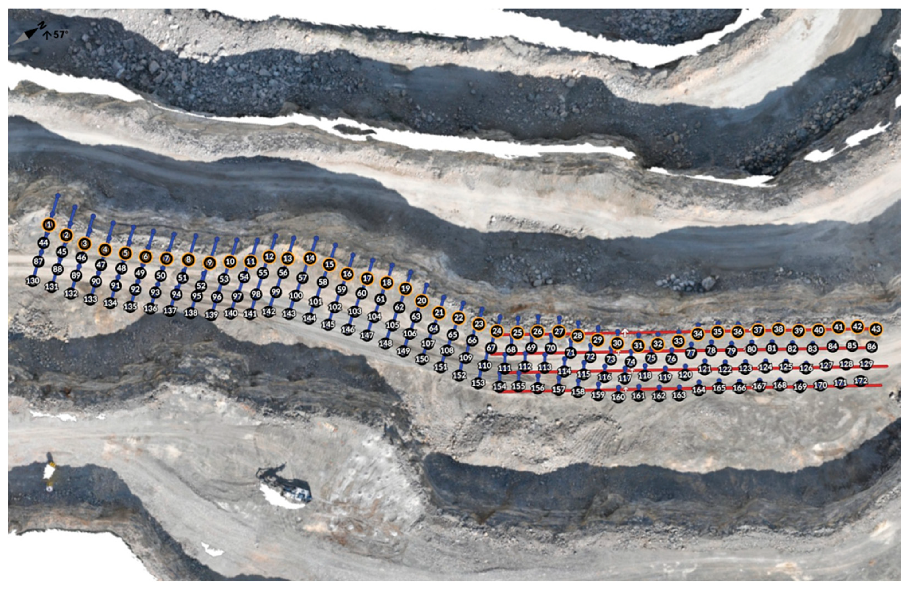
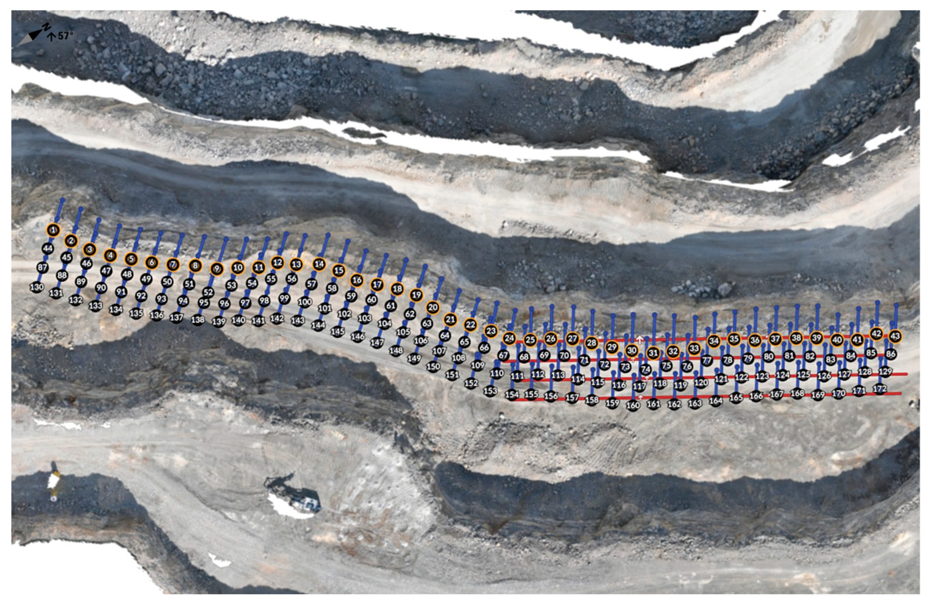
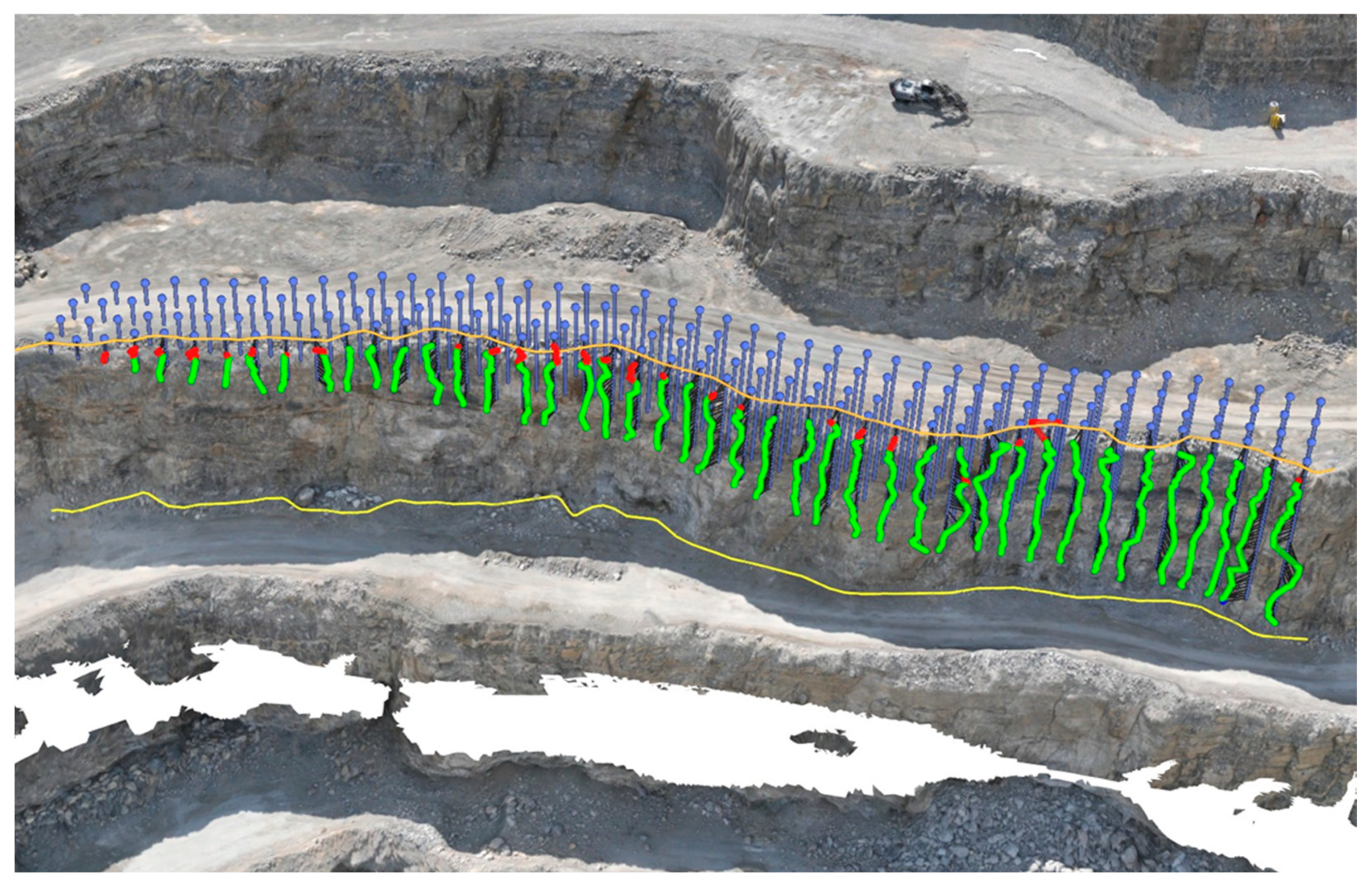
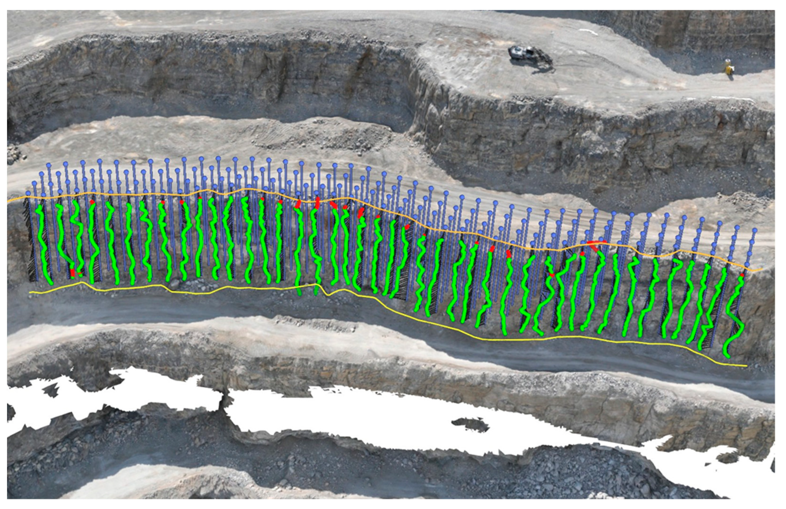
Two alternative blasting variants were developed for in-pit haul road formation. The first was peripheral blasting, where fragmented rock is transported, placed, and shaped to create a stable embankment that meets the required gradient (ramp with embankment), and the second related to profiling the road using blasting at the location of the in-pit ramp. The fundamental parameters of the drilling and blasting works for both variants are summarized in Table 1, while the blasting patterns are illustrated in Figure 2 and Figure 3, and the three-dimensional views of the drilling patterns are presented in Figure 4 and Figure 5.
The Furukawa HCR L90-E5 (Furukawa Rock Drill Co., Ltd., Tokyo, Japan) top hammer drilling rig was used for drilling boreholes. The ANFO explosive was prepared by blending ammonium nitrate (V) with fuel oil at a weight ratio of 94.0:6.0 (wt.%), and loaded into the boreholes mechanically using a UMS. The main explosive charge was primed using 450 g dynamite cardridge boosters, which were initiated with non-electric detonators.

2.2.2. Carbon and Nitrogen Oxides Emissions

Theoretical carbon and nitrogen oxide emissions for the explosives (ANFO and dynamite boosters) were determined based on explosive samples tested in a blasting chamber. In each experiment, a 500 g charge was detonated. ANFO charges were loaded into glass tubes with an inner diameter of 46 mm and subsequently positioned within a mortar in the blasting chamber. Dynamite charges were placed directly in the mortar without a glass tube. Initiation was achieved using a primer composed of 14 g of RDX (Royal Demolition Explosive) coupled with an electric instantaneous detonator. After each detonation, the resulting fumes were homogenized for three minutes and then extracted through a ventilation system over a 20 min sampling interval. COx concentrations were quantified by infrared spectroscopy (MIR 25e, ENVEA, Paris, France), whereas NOx concentrations were measured by chemiluminescence analysis (TOPAZE 32M, ENVEA, Paris, France) in accordance with standard [21]. Table 2 presents average fume volume formed during the detonation process.
In the process of forming the in-pit haul road, in addition to the energy of explosive detonation, machines were used in the phases of drilling blast holes (Furukawa HCR L90-E5 (Furukawa Rock Drill Co., Ltd., Tokyo, Japan) drilling rig), ANFO production, loading blast holes with explosives (Universal Mixing System), and muckpile extraction (Volvo EC480EL (Volvo Construction Equipment, Gothenburg, Sweden) excavator), in two variants of work.
The Furukawa HCR L90-E5 top hammer drilling rig (194 kW) has an average drilling rate of 26.4 m·h−1 and average fuel consumption during drilling process of 20.4 L·h−1. The Universal Mixing System (UMS) (353 kW) is constructed on a Scania chassis, and the operational efficiency during ANFO production and loading processes ranges between 70 and 80 kg·h−1. The average fuel consumption during the blending and loading operations was found to be between 30 and 35 L·h−1 under standard operating conditions. The Volvo EC480EL (281 kW) excavator has an average fuel consumption of 23 L·h−1 under standard operating conditions.
The machines are equipped with Tier 5 final stage emission standard compliant diesel engines (drilling rig and UMS Unit) and Tier 4 compliant engine (excavator).
Nitro and carbon oxides emissions were estimated based on Equation (1):
M E = N · H R S · P · ( 1 + D F A ) · L F A · E F B a s e
where
ME is the mass of emissions of pollutant during inventory period in g·h−1;
N is the number of engine units;
HRS is the annual hours of use in h;
P is the engine size in kW;
DFA is the deterioration factor adjustment;
LFA is the load factor adjustment;
EFBase is the vase emission factor in g·kWh−1.
The equipment used in the study (drilling rig, UMS charging unit, and excavator) was nearly new at the time of assessment. Their technical condition and maintenance status were verified by the mining authority’s engineering team, confirming that all machines operated within the manufacturer’s nominal performance specifications. For this reason, deterioration of engine performance was assumed to be negligible. Consequently, the DFA was set at the lower bound (DFA = 0) of the Stage IV/V NRMM-recommended range, representing new or early-life engines with minimal emission degradation. This approach is consistent with EU Non-Road Mobile Machinery (EU NRMM) [23] and ICCT (International Council on Clean Transportation) modeling guidelines [24], which allow reduced DFA values when engine age and maintenance records indicate limited operational deterioration.
The quantification of carbon dioxide emissions was based on the assumption of average diesel fuel consumption, with a fuel density of 832.5 kg·m3 being employed for the purpose. The estimation of emissions from machinery and vehicles was conducted using a multi-parameter approach, incorporating equipment population (N), annual operating hours (HRS), power output (P), base emission factors (EFBase), deterioration factor adjustments (DFA), and load factor adjustments (LFA). The LFA was assumed as full load (LFA = 1) for drilling operations, ANFO production and loading, and for excavation process, based on the side observation from mine authorities and the assumption that all machines are working continuously to perform designated tasks (without maneuvering).
The equipment fleet (N) was divided by technological tier and power class. Derived from this data, the study went on to create usage profiles based on age, with the annual operating hours of the equipment used as the dependent variable and the equipment’s age as the independent variable. Within each subcategory, power output (P) was allocated according to typical distribution ranges. The base emission factors (EFBase) for individual pollutants were determined as functions of both technological level and power output. The EFBase were sourced from the EU Non-Road Mobile Machinery (EU NRMM) stage-specific emission factor tables [25,26] and the Environmental Protection Agency (EPA) [27], which differentiate emission levels by power class and engine tier. Therefore, drilling rigs, mixing systems, and excavators were assigned distinct EFBase values corresponding to their certified tier and rated power. Furthermore, EPA regulations comply with EU NRMM. Subsequently, deterioration factor adjustments (DFA) were applied, also as functions of technology level and power class, to account for performance degradation over time.
The fume emission assessment considered the operating time of individual machines in two operating variants. In the case of the peripheral blasting (ramp with embankment), due to charge limitations, excavation should be divided into seven blasting series. In this scenario, the excavator is assumed to operate for 120 h (collection of spoil after each blast within 12 h and formation of the road by the excavator for 48 working hours). In the case of blasting at the location of the ramp (ramp without embankment), four blasting series are required (one series of blast holes less than 6 m, and four series of blast holes longer than 6 m). The resulting rock can then be used for production.

3. Results and Discussion

3.1. Impact of Construction Method on Fumes

As noted in Section 2.2.1, the primary distinction between constructing an in-pit haul ramp with versus without embankment lies in the additional muckpile collection. For ramp construction with an embankment, the blasted material is subsequently used for ramp construction and compaction. Nevertheless, in both approaches the fume emissions can be categorized according to three stages: drilling, explosive charging, and energetic material decomposition.
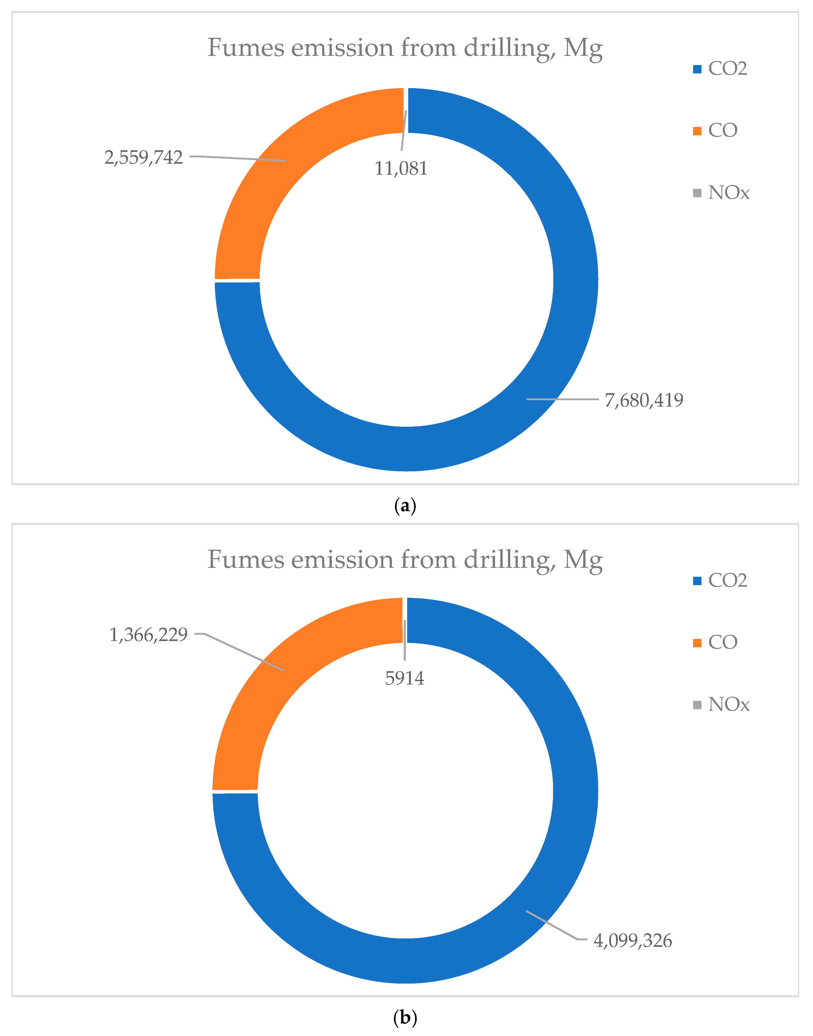
Emissions from drilling were estimated based on the design drilling documentation and the TIER 5 emission standard for the drilling rig. According to the documentation, construction with a bench embankment requires a total borehole length of approximately 3770 m, whereas the direct rock mass method requires approximately 2013 m. Given an average fuel consumption of 0.0204 m3·h−1 and an average drilling efficiency of 0.0264 m·h−1, the fume emissions were calculated, as shown in Figure 6.
Figure 6a,b demonstrate that, in both scenarios, carbon dioxide accounts for the majority of the emissions, approximately 75%. This finding is consistent with conventional fuel-to-CO2 conversion factors and established emission inventories in which CO2 dominates the exhaust mass budget [24,28]. The lowest contribution, approximately 0.11%, was attributed to NOx, reflecting the effect of TIER standards and broader regulatory efforts to minimize NOx generation [29,30]. Although the proportional composition of the fumes remains constant due to the use of the same drilling equipment, the total mass of emissions varies. For peripheral blasting (ramp with embankment), the drilling process generates approximately 10.25·106 Mg of fumes, as shown in Figure 6a, whereas blasting at the location of the ramp (ramp without embankment) generates approximately 5.41·106 Mg, shown in Figure 6b. This difference is directly attributable to the duration of the drilling operations; the peripheral blasting method requires approximately 142.8 h of drilling compared with 76.3 h for the blasting at the location of the in-pit ramp. It is important to note that these evaluations were limited to the drilling process itself, and additional maneuvering emissions were not considered.
The selected blasting method also determines borehole length and, therefore, the required explosive mass. According to the design data, seven blasting series for the construction or ramp with an embankment require approximately 17.49·106 Mg of ANFO and 77.4 kg of emulsion cartridges as primers. In contrast, blasting that will result in the ramp without embankment requires approximately 7.89·106 Mg of ANFO and the same 77.4 kg of priming material. The Uniform Mixing System for ANFO production has an efficiency of approximately 85 kg·min−1. Consequently, the required masses of 17.49·106 Mg and 7.89·106 Mg correspond to explosive charging times of approximately 4 h and 2 h, respectively. Based on TIER 5 emission factors (NOx = 72 g·h−1; CO = 240 g·h−1; and CO2 = 3.167 kg per 1 kg diesel combusted), the total emissions from the loading process were estimated at approximately 0.2–0.4·106 Mg (Table 3).
However, it should be noted that in many blasting operations in Dubie, open-pit mine explosive charging is performed manually. In such cases, the emissions from the charging equipment would be 0 kg. The impact of different scenarios was broadly discussed in [31].
The overall emissions from ANFO decomposition were estimated using ballistic mortar tests and the methodology described in the methods section (Section 2.2), applying emission factors per kilogram of explosive consumed. The results, based on the total explosive mass of ANFO and emulsion primers, are presented in Table 4.
The overall fume emission from explosive detonation depends on the in-pit ramp construction method. Table 4 indicates that in-pit road construction without embankment is more environmentally friendly compared to the method involving embankment. Blasting that results in ramp construction with embankment emits approximately 2.2 times the mass of CO2, CO, and NOx compared with direct rock mass blasts (4719.6 vs. 2140.7 kg CO2; 330.2 vs. 149.2 kg CO; 396.3 vs. 178.9 kg NOx). Taking into consideration the total mass of explosives that would be used in seven blasting series, the scale effect is clearly visible. However, it should also be considered that, in real conditions, the confinement, explosive form (e.g., bulk, cartridge), and looser burden/spacing will produce larger absolute emissions [22]. Furthermore, Table 4 indicates that priming (dynamite cartridge charge) contribution is negligible in mass terms for both configurations; the dynamite priming contributes about 0.46–1.02% of the CO2 mass and well under 1% of CO and NOx compared to ANFO charge. Primers are small in mass but critical for reliable detonation; their chemical signature can matter for local high-temperature chemistry, yet the data confirm that the bulk emissions scale with the ANFO charge. This aligns with experimental comparisons showing that small booster primer charges produce little of the total post-blast fume mass when used with much larger main charges [32,33,34,35,36]. Biessikirski et al. have reported that the use of different priming explosives can reduce overall fume emissions by up to 9% [22]. Furthermore, peripheral blasting (ramp with embankment) is generally carried out in the same area where the in-pit ramp will be constructed. Consequently, it is necessary to transport the blasted muckpile to form the ramp and establish the embankment. This process involves excavation (approximately 12 h) and ramp forming (approximately 48 h) for a total of approximately 60 h of additional machinery operation. Based on the TIER 5 emission indices (Table 5) and an excavator average fuel consumption of 0.0239 m3·h−1, the resulting fume emissions were calculated and are presented in Table 5 and Figure 7.
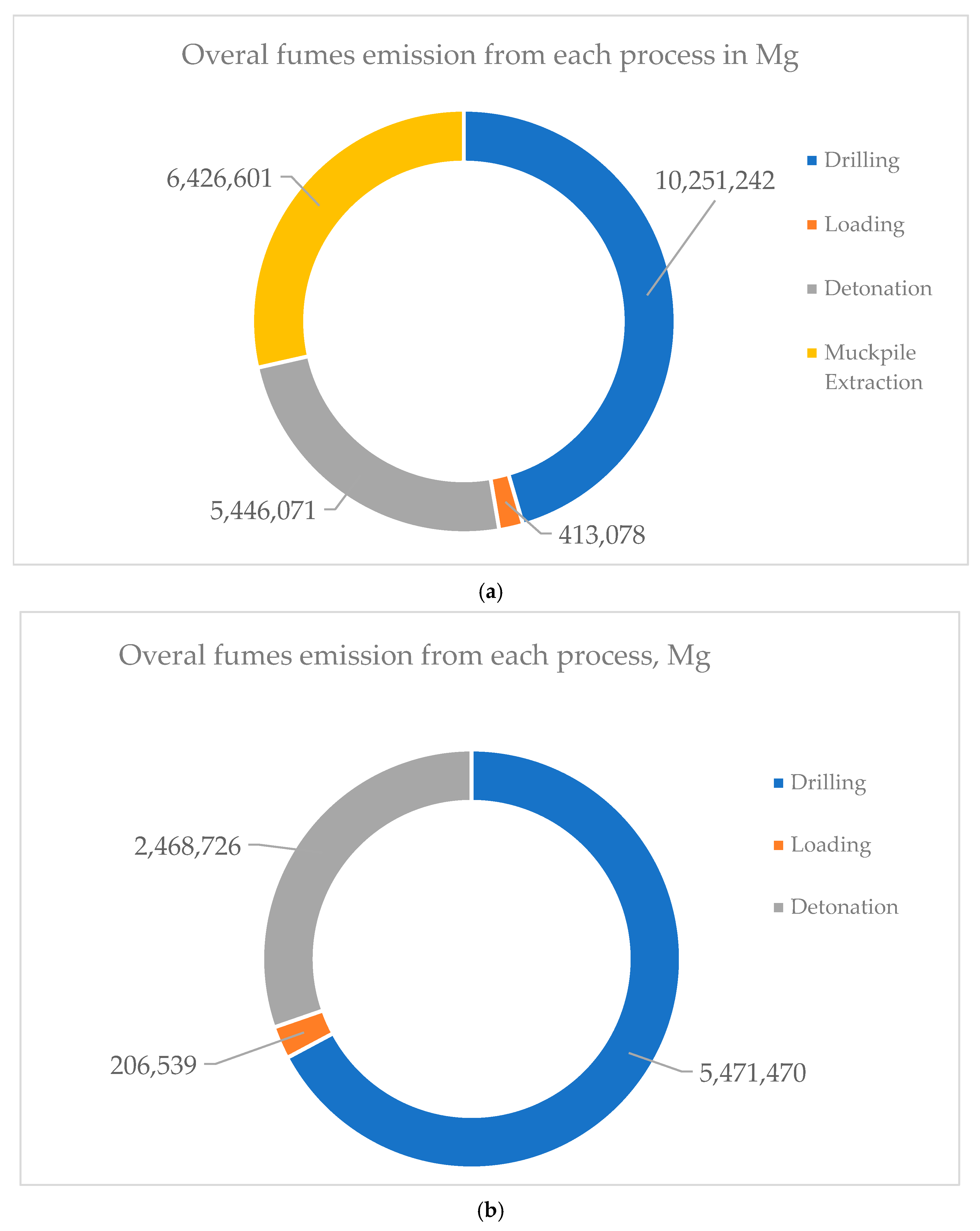
Figure 7a indicates that in the case of the peripheral blasting (ramp with embankment) method, fume emissions are largely generated by drilling (10.25·106 Mg of fumes), muckpile extraction (6.43·106 Mg of fumes), and detonation (5.45·106 Mg of fumes), with smaller contributions from loading (0.41·106 Mg of fumes). The absence of muckpile extraction emission, in the case of in-pit ramp construction without embankment, as shown in Figure 7b, reflects that muckpile is not used for construction process but only as the regular mining product. Furthermore, the construction of in-pit ramp without embankment, as shown in Figure 7b, reveals that drilling (5.47·106 Mg of fumes) and detonation (2.47·106 Mg of fumes) dominate, while explosive charging (0.41·106 Mg of fumes) has minor significance. However, the open-pit mine blasting service can perform explosive charging by hand that will also slightly decrease the overall gross fumes. What is more, evaluated data indicates that in-ramp construction with embankment demands substantial drilling effort, which significantly increases fume emissions from diesel-powered rigs. The detailed analysis revealing the impact of either the detonation process or machine work is presented in Figure 8 and Figure 9.
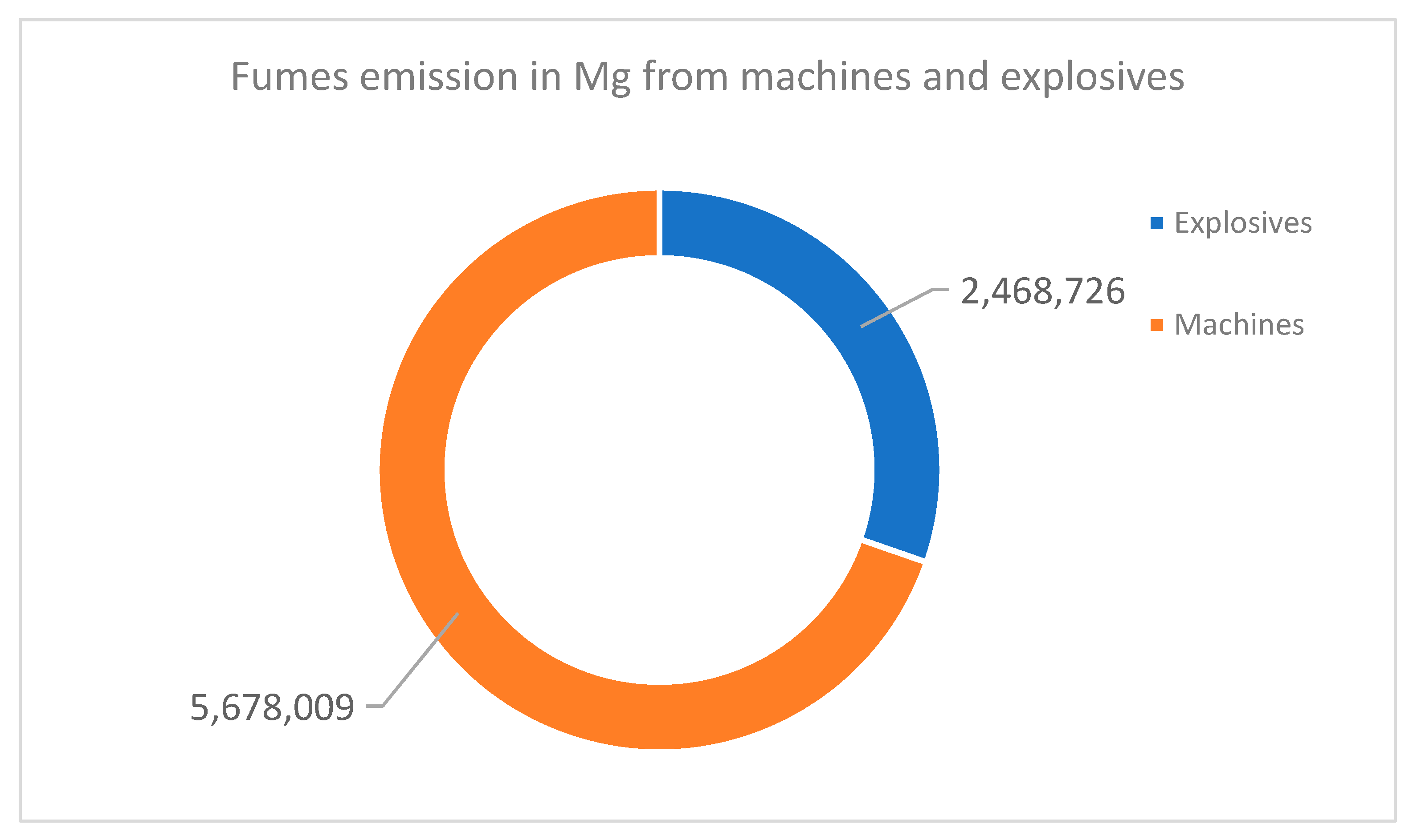
Figure 8 and Figure 9 highlight a consistent pattern, showing that machinery contributes the majority of emissions. For the blasting method, machines account for 17.09·106 Mg of fumes compared with 5.45·106 Mg from explosives. For the in-pit ramp with embankment, the balance is 5.68·106 Mg from machines and 2.47·106 Mg from explosives. Although explosives are the source of the most toxic fume species (CO, NOx), machinery dominates the carbon footprint (CO2) through sustained fuel combustion. This shows that attempts to mitigate potential fumes should be directed to potential machine selection. The overall fume composition characteristic is presented in Figure 10.
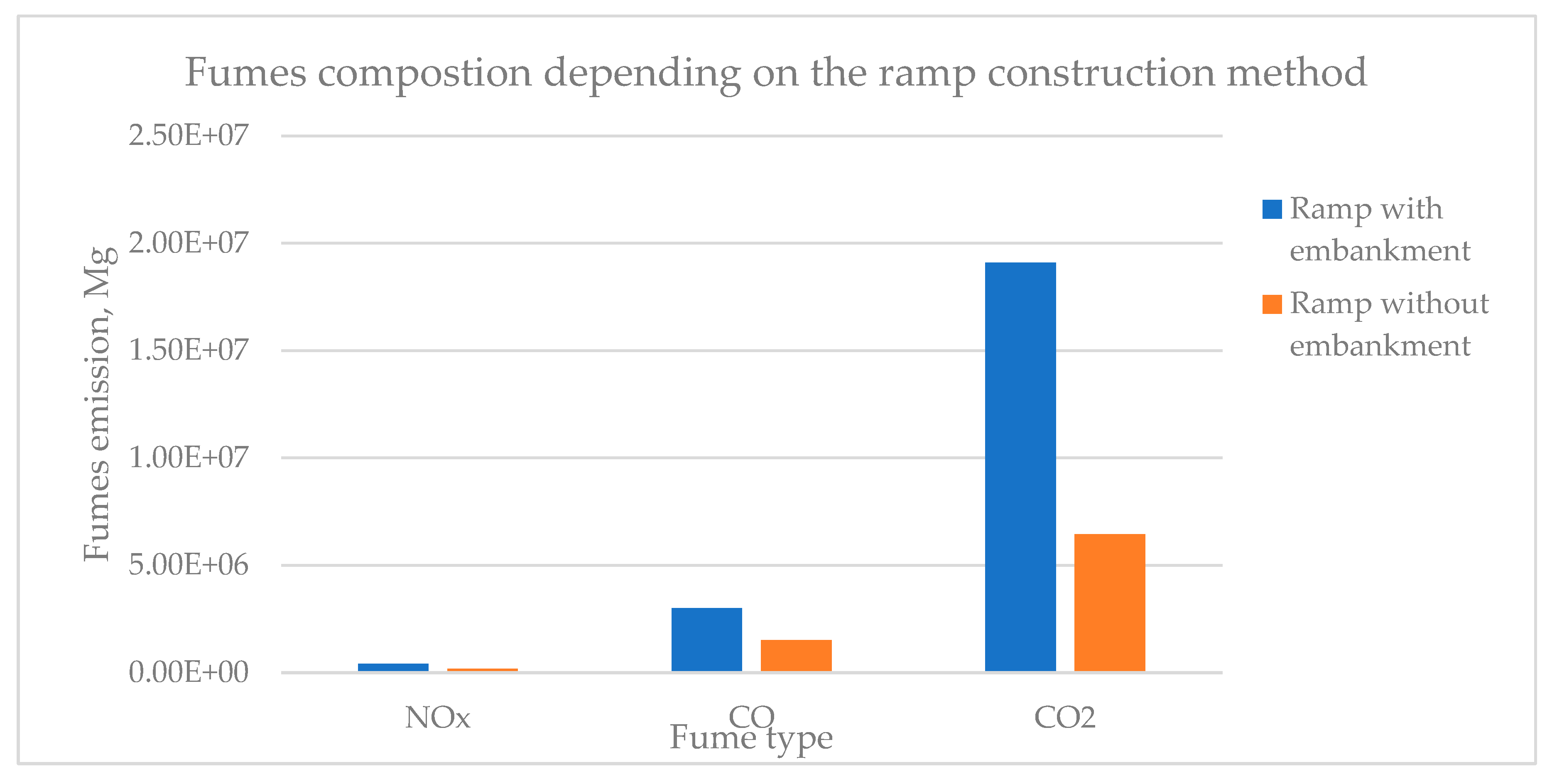
According to Figure 10, CO2 is the dominant emission in both strategies, with approximately 19 tons for peripheral blasting (ramp with embankment) and approximately 7·106 Mg for the in-pit ramp without embankment. This reflects the major contribution of diesel combustion and detonation chemistry. The approximately 2.5 tons and 1.5 tons of CO emission is lower in tonnage than CO2; however, due to the high toxicity of CO this can be a major concern in the case of the vast introduction of mining force to the blast site. Additionally, NOx also appears in much smaller quantities (smaller than 0.5·106 Mg, Figure 10), and it is also critical due to its acute toxicity. This species distribution aligns with published field measurements showing that CO2 dominates mass inventories, while CO and NOx govern occupational health risk [22].
Figure 10 indicates that in haul ramp construction using the rock embankment method exhibits higher overall emissions, driven by increased CO2 and CO from machinery and additional handling (muckpile transportation and embankment formation). Moreover, this method requires much more drilling that results in the increased mass of explosives consumption in comparison to the second method. This makes it less favorable in terms of greenhouse gas inventory and potential exposure to incomplete combustion products.
The results of this study are consistent with published work on blast-induced fumes and emissions from non-road diesel equipment. Biessikirski et al. [22] demonstrated that CO and NOx emissions from the ANFO detonation scale correlate primarily with total explosive mass and confinement, which aligns with the observed 2.2-fold increase in detonation-related fumes for the bench embankment variant, where explosive consumption was more than doubled. Similarly, Attalla et al. [33] and Mainiero et al. [34] reported that the most hazardous fume constituents (CO and NOx) arise predominantly from incomplete post-detonation reactions, whereas the majority of total emission mass originates from diesel combustion by support equipment. Our findings corroborate this distinction: machine operation accounted for over 70–80% of CO2 emissions in both construction approaches. Furthermore, the literature on haulage energy consumption and fuel-related emissions [8,9,10] supports the conclusion that operational activities, particularly drilling and excavation, dominate the carbon footprint in open-pit settings. Therefore, the relative differences observed between the two ramp construction methods are consistent with established mechanistic explanations in existing research.

3.2. Deposit Management

Blasting at the ramp location in order to profile the rock mass into the desired shape does not involve the formation of a rock embankment or subsequent compaction; however, it requires a higher degree of precision and detailed planning in the design of blasting works. This approach offers economic benefits through the reduction in drilling and explosive consumption costs. However, it simultaneously entails increased operational expenses associated with muckpile extraction and elevated emissions of nitrogen oxides (NOx) and carbon oxides (COx) from diesel-powered machinery.
As noted previously, the ramp constructed using the embankment method is formed by developing a built-up structure from blasted rock material. The fragmented rock is transported, placed, and shaped to create a stable embankment that meets the required gradient, width, and bearing capacity for haul truck operation. In this configuration, the triangular cross-section of the embankment extends laterally beyond the designed roadway profile. Consequently, a portion of the underlying deposit becomes inaccessible for future extraction. In the present case study, and according to operational practice at the Holcim Dubie quarry, the footprint of the embankment would occupy approximately 1500 m2, corresponding to a cathetus length of 200 m and a hypotenuse of approximately 15 m. Given the bench height of 20 m, this geometry results in an estimated 30,000 m3 of dolomite that becomes permanently incorporated into the embankment and which therefore cannot be recovered. Extrapolating this effect to all operational levels at Holcim Dubie, requiring five in-pit haul ramps, would result in a cumulative loss of approximately 150,000 m3 of extractable deposit. In contrast, when the in-pit ramp is created directly within the intact rock mass (i.e., without the formation of a rock embankment), the blasted material remains fully available for processing. Based on the drilling plan and volumetric assessment performed in Strayos software (version 1.0.1), it is estimated that the direct-blasting variant would additionally yield for production purposes approximately 25,000 m3 of recoverable dolomite relative to the embankment-based method.
Moreover, an additional potential operational advantage of crating the in-pit ramp without embankment lies in its possible greater structural stability, as suggested by the open-pit mine authorities based on their long-term observation, as haul roads formed directly in the intact rock mass should be less susceptible to surface run-off erosion and require fewer maintenance interventions; however, proper research has to be conducted to confirm this statement. Furthermore, this technique permits the application of steeper slope angles on the haul roads’ sides due to the inherent strength of the rock structure. The ramp construction time using this technique is typically shorter, as it requires shorter blast holes and involves less time-consuming removal of fragmented material, which can subsequently be utilized for production purposes. This method is particularly advantageous when the ramp is intended for long-term use, given the greater effort required for its eventual removal. Such ramps are typically constructed when the mine operation approaches its final design boundaries.
In contrast, the blasting that results in the construction of the ramp with embankment is generally more time and cost inefficient compared to direct blasting methods. This results from the need for longer drill holes, increased haulage of blasted material, and a greater number of blasting operations to complete the ramp formation. Additionally, the prolonged operation times of mechanical equipment contribute to significantly higher emissions of nitrogen and carbon oxides. From a structural standpoint, haul roads built from rock embankments are more vulnerable to washouts, slope failures, and other degradation processes, requiring more frequent repairs. They also occupy a larger surface area at the operational level due to the necessity of maintaining safe slope angles.
This study provides several contributions that extend existing research on blasting emissions and haul road construction. Firstly, to the authors’ knowledge, this is the first work to compare two alternative blasting-based ramp construction strategies in terms of their combined explosive-related and diesel-equipment-related emissions. Previous studies have focused either on explosive fume generation [22,28,29,30,31,32] or on fuel-related emissions from mining machinery [8,9,10], but not on their joint interaction within a specific engineering task. Secondly, the analysis integrates resource-management implications by quantifying the recoverable dolomite volume preserved through direct in situ ramp formation, which has not been previously discussed in the ramp construction literature. Thirdly, the study demonstrates the operational and environmental trade-offs that arise from differing blast geometries and muckpile-handling requirements, providing practical guidance for mine-planning decisions. These elements constitute the incremental research contribution beyond the existing body of knowledge.

4. Conclusions

This study compared two blasting-based approaches for constructing an in-pit haul ramp in a hard-rock open-pit dolomite mine, integrating emissions from explosive detonation and diesel-powered equipment with resource-management considerations. The results demonstrate clear differences between the two engineering strategies and provide the first comprehensive quantification of fume emissions associated specifically with ramp construction.
The analysis shows that blasting at the location of the ramp (ramp without embankment) generates substantially lower total fume emissions than the ramp embankment approach (peripheral blasting). The reduction is primarily driven by shorter drilling requirements, lower explosive consumption, and the elimination of additional muckpile handling needed for embankment formation. Machine operation, rather than explosive detonation, was confirmed to be the dominant source of CO2 emissions in both scenarios, while explosives contributed most to NOx and CO generation. Importantly, direct blasting enables the preservation of approximately 150,000 m3 of dolomite, which can be recovered for production, and additional 25,000 m3 instead of being irreversibly incorporated into embankment structures.
Despite these advantages, several limitations must be acknowledged. First, the findings are site-specific and reflect the geological, geometric, and operational conditions of the Dubie dolomite deposit. Although the relative trends are expected to hold for other hard-rock operations using comparable bench heights, drilling patterns, and equipment classes, absolute emission values may differ in deposits with markedly different mechanical properties (e.g., sandstone, basalt, or schist) or in mines where regulatory charge limits and topographic constraints vary. Second, the study applied deterministic emission modeling; while uncertainty sources (e.g., variability in fume chamber measurements, emission-factor ranges, and equipment load fluctuations) were explicitly discussed, a full stochastic uncertainty quantification was beyond scope. Third, boundary conditions, such as groundwater inflow, confinement variability, or local burden heterogeneity, were held constant for both variants, as the objective was to examine method-driven differences rather than simulate all possible environmental influences.
Notwithstanding these constraints, the research provides a novel contribution by integrating explosive-related and diesel-equipment emissions into a unified assessment of ramp-construction strategies, quantifying the resource-efficiency implications of alternative blast designs, and demonstrating the operational and environmental trade-offs that accompany practical engineering choices in surface mining. These insights can support mine planners in selecting ramp-construction methods that balance production efficiency, resource stewardship and environmental performance.
Future work should extend this approach to other lithologies, incorporate probabilistic uncertainty analysis, and investigate how variations in burden, spacing, confinement, or groundwater conditions influence fume generation in complex geological environments.

Author Contributions

Conceptualization, M.D. (Michał Dudek) and A.B.; methodology, M.D. (Michał Dudek); software, M.D. (Michał Dudek); validation, A.B. and M.D. (Michał Dworzak); formal analysis, M.D. (Michał Dudek), M.D. (Michał Dworzak) and A.B.; investigation, M.D. (Michał Dudek), M.D. (Michał Dworzak) and A.B.; resources, M.D. (Michał Dudek); data curation, M.D. (Michał Dudek) and A.B.; writing—original draft preparation, M.D. (Michał Dudek), M.D. (Michał Dworzak) and A.B.; writing—review and editing, M.D. (Michał Dudek), M.D. (Michał Dworzak) and A.B.; visualization, M.D. (Michał Dudek), M.D. (Michał Dworzak) and A.B.; supervision, A.B.; and funding acquisition, M.D. (Michał Dworzak) and A.B. All authors have read and agreed to the published version of the manuscript.

Funding

The authors wish to thank the Faculty of Civil Engineering and Resource Management at the AGH University of Krakow for the financial support of research no. 16.16.100.215.

Institutional Review Board Statement

Not applicable.

Informed Consent Statement

Not applicable.

Data Availability Statement

The original contributions presented in the study are included in the article. Further inquiries can be directed to the corresponding author.

Conflicts of Interest

Author Michał Dudek was employed by the KOSD Przedsiębiorstwo Produkcyjne PP Sp. z o.o. Sp. k., Grupa Holcim. The remaining authors declare that the research was conducted in the absence of any commercial or financial relationships that could be construed as a potential conflict of interest.

References

  1. Thompson, R. Mine Haul Road Design and Management Best Practices for Safe and Cost-Efficient Truck Haulage. In Proceedings of the Society for Mining, Metallurgy and Exploration Annual Meeting & Exhibit, Phoenix, AZ, USA, 28 February–3 March 2010; Society for Mining, Metallurgy and Exploration (SME): Littleton, CO, USA, 2010; pp. 1–10. [Google Scholar]
  2. Kaufman, W.W.; Ault, J.C. Design of Surface Mine Haulage Roads—A Manual; United States Bureau of Mines (USBM), United States Department of the Interior: Washington, DC, USA, 1977; pp. 1–49. [Google Scholar]
  3. Tannant, D.; Regensburg, B. Guidelines for Mine Haul Road Design; University of British Columbia Library: Vancouver, BC, Canada, 2010; pp. 1–111. [Google Scholar]
  4. Hustrulid, W.A.; Kuchta, M.; Martin, R.K. Open Pit Mine Planning and Design, 3rd ed.; CRC Press: Leiden, The Netherlands, 2013; pp. 1–1288. [Google Scholar]
  5. Darling, P. SME Mining Engineering Handbook, 3rd ed.; Society for Mining, Metallurgy and Exploration (SME): Littleton, CO, USA, 2011; pp. 1–1837. [Google Scholar]
  6. Mohutsiwa, M.; Musingwini, C. Parametric estimation of capital costs for establishing a coal mine: South Africa case study. J. S. Afr. Inst. Min. Metall. 2015, 115, 789–797. [Google Scholar] [CrossRef]
  7. Nancel-Penard, P.; Parra, A.; Morales, M.; Díaz, C.; Widzyk-Capehart, E. Value-optimal design of ramps in open pit mining. Arch. Min. Sci. 2019, 64, 399–413. [Google Scholar] [CrossRef]
  8. Purhamadani, E.; Bagherpour, R.; Tudeshki, H. Energy consumption in open-pit mining operations relying on reduced energy consumption for haulage using in-pit crusher systems. J. Clean. Prod. 2021, 291, 125228. [Google Scholar] [CrossRef]
  9. Tadubana, G.K. Prediction of Fuel Consumption of Haulage Trucks in Open Pit Mines. Master’s Thesis, Botswana International University of Science & Technology, Palapye, Botswana, 2021. [Google Scholar]
  10. Kecojevic, V.; Komljenovic, D. Haul truck fuel consumption and CO2 emission under various engine load conditions. Min. Eng. 2010, 62, 44–48. [Google Scholar]
  11. Akay, A.E.; Aruga, K.; Bettinger, P.; Sessions, J. Using optimisation techniques in designing forest roads and road networks. J. Fac. For. Istanb. Univ. 2013, 15, 49–62. [Google Scholar]
  12. Aleksandrova, E. Ikonomicheski podhod pri proektiraneto na rudnitsi. In Proceedings of the Mezhdunarodna Nauchna Konferentsia “The Challenges Facing Science in Connection with Bulgaria’s Membership in the EU”, Stara Zagora, Bulgaria, 8 June 2007. [Google Scholar]
  13. Baek, J.; Cho, Y. A new method for haul road design in open-pit mines to support efficient truck haulage operations. Appl. Sci. 2017, 7, 747. [Google Scholar] [CrossRef]
  14. Morales, N.; Nancel-Penard, P.; Parra, A. An integer linear programming model for optimising open pit ramp design. In Proceedings of the 38th APCOM Proceedings 2017, Golden, CO, USA, 9–11 August 2017; Session 11. pp. 9–16. [Google Scholar]
  15. Yarmuch, J.; Brazil, M.; Rubinstein, H.; Thomas, D.A. Optimum ramp design in open pit mines. Comput. Oper. Res. 2020, 115, 104739. [Google Scholar] [CrossRef]
  16. Terziyski, D.; Kaykov, D. Haul road design optimization approach following technological constraints in open-pit mining. Sustain. Extr. Process. Raw Mater. J. 2022, 3, 78–88. [Google Scholar] [CrossRef]
  17. Aleksandrova, E. Guide to the Exercises on Technology in Open-Pit Mining of Minerals (Technological Schemes of Driving Open-Pit Mines); Avangard Prima: Sofia, Bulgaria, 2013. (In Bulgarian) [Google Scholar]
  18. Koprev, I. Technology of Extraction of Rock Facing Materials; Avangard Prima: Sofia, Bulgaria, 2016. (In Bulgarian) [Google Scholar]
  19. Zlatanov, P.; Aleksandrova, E. Course Design Guide for Open Pit Mining Technologist; Komlivest-LM: Sofia, Bulgaria, 2005. (In Bulgarian) [Google Scholar]
  20. Thompson, R.J.; Visser, A.T. The functional design of surface mine haul roads. J. S. Afr. Inst. Min. Metall. 2000, 100, 169–180. [Google Scholar]
  21. EN 13631-16:2004; Explosives for Civil Uses. High Explosives. Part 16: Detection and Measurement of Toxic Gases. European Committee for Standardization: Brussels, Belgium, 2004.
  22. Biessikirski, A.; Dworzak, M.; Pytlik, M.; Nachlik, S. Impact of the Type of Energetic Material on the Fume Emission in Open-Pit Mining. Sustainability 2025, 17, 2075. [Google Scholar] [CrossRef]
  23. European Commission. Technical Guidance Document on Monitoring and Emission Reporting for Non-Road Mobile Machinery (NRMM) under Regulation (EU) 2016/1628; Publications Office of the European Union: Brussels, Belgium, 2018; pp. 1–87. [Google Scholar]
  24. Dallmann, T.; Menon, A. Technology Pathways for Diesel Engines Used in Non-Road Vehicles and Equipment; International Council on Clean Transportation: Washington, DC, USA, 2016. [Google Scholar]
  25. European Parliament and Council. Directive 97/68/EC of 16 December 1997 on the Approximation of the Laws of the Member States Relating to Measures Against the Emission of Gaseous and Particulate Pollutants from Internal Combustion Engines to Be Installed in Non-Road Mobile Machinery. Off. J. Eur. Union 1998, L 59, 1–86. Available online: https://eur-lex.europa.eu/legal-content/EN/TXT/PDF/?uri=CELEX:01997L0068-20070101 (accessed on 22 September 2025).
  26. European Commission. Commission Directive 2010/22/EU of 15 March 2010 Amending, for the Purposes of Their Adaptation to Technical Progress, Directives 80/720/EEC, 86/298/EEC, 86/415/EEC, 87/402/EEC, 2000/25/EC, 2005/13/EC and 2009/60/EC of the European Parliament and of the Council Relating to the Type-Approval of Agricultural or Forestry Tractors. Off. J. Eur. Union 2010, L 129, 1–34. Available online: https://eur-lex.europa.eu/legal-content/EN/TXT/PDF/?uri=CELEX:32010L0022 (accessed on 22 September 2025).
  27. Environmental Protection Agency (EPA). Control of Emissions of Air Pollution from Non-Road Diesel Engines and Fuel. Fed. Regist. 2004, 69, 38958–38988. [Google Scholar]
  28. Babamohammadi, S.; Birss, A.R.; Pouran, H.; Pandhal, J.; Borhani, T.N. Emission control and carbon capture from diesel generators and engines: A decade-long perspective. Carbon Capture Sci. Technol. 2025, 14, 100379. [Google Scholar] [CrossRef]
  29. Piumetti, M.; Bensaid, S.; Fino, D.; Russo, N. Catalysis in Diesel engine NOx aftertreatment: A review. Catal. Struct. React. 2015, 1, 155–173. [Google Scholar] [CrossRef]
  30. Lee, K.; Lee, J.; Lee, S.; Oh, K.; Jang, S. Fuel Consumption and Emission Reduction for Non-Road Diesel Engines with Electrically Heated Catalysts. Catalysts 2023, 13, 950. [Google Scholar] [CrossRef]
  31. Dudek, M.; Dworzak, M.; Biessikirski, A. Impact of Blasting Scenario for Construction of in-Pit Ramp on the Fumes Emission. Sustainability, 2025; submitted. [Google Scholar]
  32. Menéndez, J.; Merlé, N.; Fernández-Oro, J.M.; Galdo, M.; Álvarez de Prado, L.; Loredo, J.; Bernardo-Sánchez, A. Concentration, Propagation and Dilution of Toxic Gases in Underground Excavations under Different Ventilation Modes. Int. J. Environ. Res. Public Health 2022, 19, 7092. [Google Scholar] [CrossRef] [PubMed]
  33. Attalla, M.I.; Day, S.J.; Lange, T.; Lilley, W.; Morgan, S. NOx emissions from blasting operations in open-cut coal mining. Atmos. Environ. 2008, 42, 7874–7883. [Google Scholar] [CrossRef]
  34. Mainiero, R.J.; Harris, M.L.; Rowland, J.H. Dangers of toxic fumes from blasting. In Proceedings of the 33rd Annual Conference on Explosives and Blasting Technique, Nashville, TN, USA, 28–31 January 2007; pp. 1–6. [Google Scholar]
  35. Rowland, J.H.; Mainiero, R.; Hurd, D.A. Factors Affecting Fumes Production of an Emulsion and ANFO/Emulsion Blends. In Proceedings of the 27th ISEE Annual Conference on Explosives and Blasting Technique, Orlando, FL, USA, 28–31 January 2001; pp. 133–141. [Google Scholar]
  36. Suceska, M.; Tumara, S.; Skrlec, V.; Stankovic, S. Prediction of concentration of toxic gases produced by detonation of commercial explosives by thermochemical equilibrium calculations. Def. Technol. 2022, 18, 2181–2189. [Google Scholar] [CrossRef]
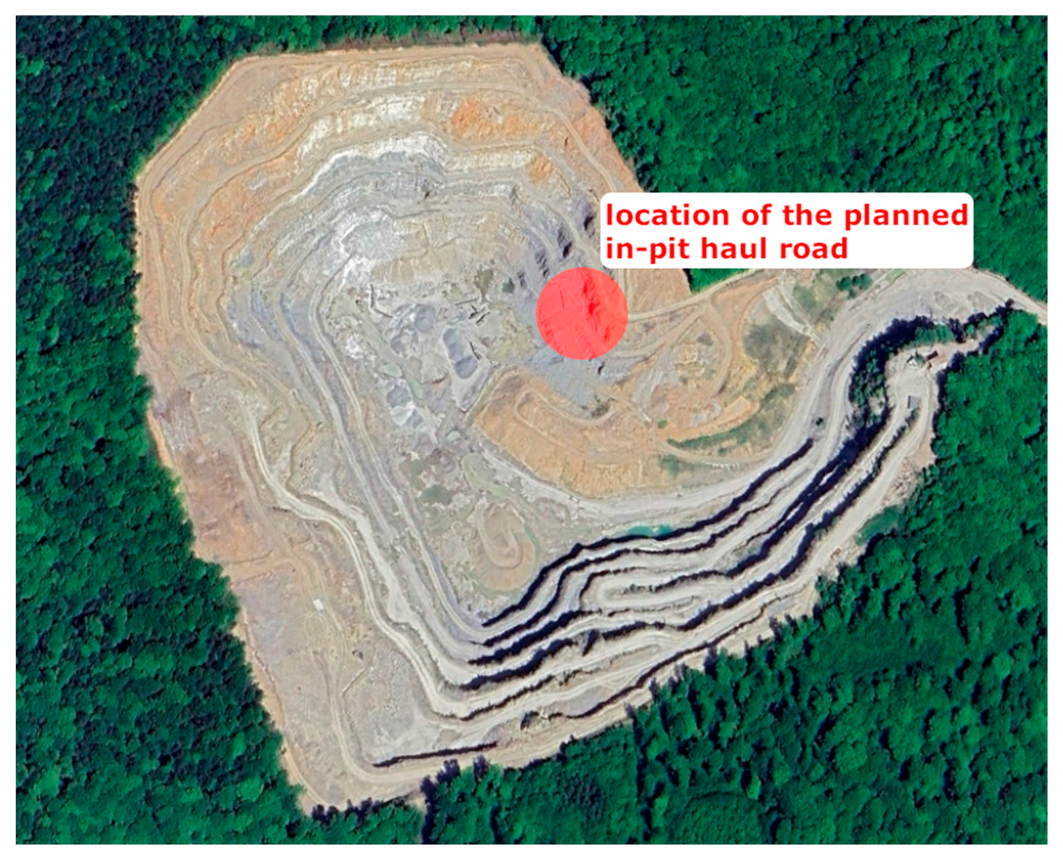
Figure 1. The location of the planned in-pit haul road in Dubie open-pit dolomite mine (source: https://www.google.com/maps, access date: 1 October 2025).
Applsci 15 12310 g001
Figure 2. Shot layout of peripheral blasting (ramp with embankment).
Applsci 15 12310 g002
Figure 3. Shot layout for blasting at the location of the ramp (ramp without embankment).
Applsci 15 12310 g003
Figure 4. Three-dimensional drilling pattern of peripheral blasting (ramp with embankment).
Applsci 15 12310 g004
Figure 5. Three-dimensional drilling pattern of blasting at the location of the ramp (ramp without embankment).
Applsci 15 12310 g005
Figure 6. Fume emissions in Mg from drilling works in the case of blasting works for construction: (a) in-pit ramp with embankment, and (b) in-pit ramp without embankment (calculation).
Applsci 15 12310 g006
Figure 7. Overall fume emissions in Mg depending on the process for (a) in-pit ramp construction with embankment, and (b) in-pit ramp construction without embankment (calculation and experimental).
Applsci 15 12310 g007
Figure 8. Comparison of fume emissions in Mg depending on the source, from in-pit ramp construction without embankment (calculation and experimental).
Applsci 15 12310 g008
Figure 9. Comparison of fume emissions in Mg depending on the source, from in-pit ramp construction with embankment (calculation and experimental).
Applsci 15 12310 g009
Figure 10. Breakdown of emission by gas species regarding the method of in-pit haul road preparation.
Applsci 15 12310 g010
Table 1. Parameters of drilling and blasting works for blasting with bench embankment variant and blasting directly in the rock mass variant.
ParameterBlasting at the
Location of the Ramp
(Ramp Without Embankment)
Peripheral Blasting (Ramp with
Embankment)
Number of rows44
Number of boreholes172172
Boreholes depth range, m1.9–22.1 21.0–23.0
Subdrill, m0.50.5
Hole diameter, mm8989
Total drilling length, m2012.13769.8
Average face burden, m3.33.4
Average pattern burden, m3.43.3
Average spacing, m3.83.8
Average bench height, m11.321.2
Rock volume, m324,964.947,476.9
Total ANFO explosives weight, kg7883.717,478.9
Number of boosters172172
Total weight of booster explosives, kg77.477.4
Table 2. Average fume volume formed during detonation test (experimental) [22].
Type of ExplosivesFumes Volume, m3⋅kg−1
CO2CONOx
ANFO0.14450.01640.0131
Dynamite0.15130.00570.00139
Table 3. Emissions from explosive charging depend on the in-pit ramp construction method (calculation and experimental).
ParameterFume Emission, kg
CO2CONOx
Index value, in the case of CO2 kg·dm−3, other: g·h−1316724072
In-pit ramp with embankment41,1711.080.29
In-pit ramp without embankment20,5860.540.15
Table 4. Fume emission from explosives’ detonation depending on in-pit ramp construction method (calculation based on experimental).
Type of ConstructionExplosiveFume Emission, kg
CO2CONOx
Ramp with embankmentANFO4697.8329.7396.1
Priming21.80.50.2
Overall4719.6330.2396.3
Ramp without embankmentANFO2118.9148.7178.7
Priming21.80.50.2
Overall2140.7149.2178.9
Table 5. Overall fume emission from each construction stage of in-pit haul road.
Mining MethodOverall Fume Emission from Each Construction Stage, tons
DrillingLoadingDetonationMuckpile Extraction
Blasting at the location of the ramp (ramp without embankment)5.4710.2072.4690.000
Peripheral blasting (ramp with embankment)10.2510.4135.4466.427
Disclaimer/Publisher’s Note: The statements, opinions and data contained in all publications are solely those of the individual author(s) and contributor(s) and not of MDPI and/or the editor(s). MDPI and/or the editor(s) disclaim responsibility for any injury to people or property resulting from any ideas, methods, instructions or products referred to in the content.